EP0701104A2 - Laser sheet triangulation method and device for on-line measurement of moving profiles - Google Patents
Laser sheet triangulation method and device for on-line measurement of moving profiles Download PDFInfo
- Publication number
- EP0701104A2 EP0701104A2 EP95112652A EP95112652A EP0701104A2 EP 0701104 A2 EP0701104 A2 EP 0701104A2 EP 95112652 A EP95112652 A EP 95112652A EP 95112652 A EP95112652 A EP 95112652A EP 0701104 A2 EP0701104 A2 EP 0701104A2
- Authority
- EP
- European Patent Office
- Prior art keywords
- profile
- laser beam
- light
- ccd camera
- light section
- Prior art date
- Legal status (The legal status is an assumption and is not a legal conclusion. Google has not performed a legal analysis and makes no representation as to the accuracy of the status listed.)
- Withdrawn
Links
Images

Classifications
-
- G—PHYSICS
- G01—MEASURING; TESTING
- G01B—MEASURING LENGTH, THICKNESS OR SIMILAR LINEAR DIMENSIONS; MEASURING ANGLES; MEASURING AREAS; MEASURING IRREGULARITIES OF SURFACES OR CONTOURS
- G01B11/00—Measuring arrangements characterised by the use of optical techniques
- G01B11/24—Measuring arrangements characterised by the use of optical techniques for measuring contours or curvatures
Definitions
- the invention relates to a light section triangulation method for on-line measurement of moving profiles, in which laser light is directed onto a profile and the radiation reflected from the light section is recorded by means of a CCD camera arranged at an angle of preferably 45 ° to the direction of irradiation .
- the light emitted by a laser source is dispersed by suitable optics in such a way that the laser beam is imaged linearly on the object, such as the profile, and reflected.
- the laser beam has a corresponding (track) width.
- This method has the disadvantage of a low resolution accuracy, the limits of which are determined by the relative movement of the profile to be measured during the exposure time.
- the relative movement can be composed both by the feed speed of the object to be measured and by transverse movements of this object, which can occur due to a lack of guidance, particularly in the case of soft materials.
- the light beam is point-shaped or spot-shaped, i.e. on a smaller area of the object (profile) than before, results in a correspondingly higher light intensity at the object location and with the rays reflected from there, which leads to a shortening of the exposure time, which is necessary for the mapping of this point (spots).
- the entire profile is composed of a plurality of pixels, each of which is depicted more sharply, which, in a row, form a track which is (essentially) transverse to the direction of advance of the profile to be measured.
- the laser beam is scanned so light-dark that a light grid is formed.
- this light grid can be measured using a sub-pixel algorithm, preferably with a resolution in the horizontal direction of 0.25 mm and in the direction perpendicular to this of 0.1 mm.
Abstract
Description
Die Erfindung betrifft ein Lichtschnitt-Triangulations-Verfahren zur on-line-Vermessung von bewegten Profilen, bei denen Laserlicht auf ein Profil gelenkt und die aus dem Lichtschnitt reflektierte Strahlung mittels einer unter einem Winkel von vorzugsweise 45° zur Einstrahlungsrichtung angeordneten CCD-Kamera aufgenommen wird.The invention relates to a light section triangulation method for on-line measurement of moving profiles, in which laser light is directed onto a profile and the radiation reflected from the light section is recorded by means of a CCD camera arranged at an angle of preferably 45 ° to the direction of irradiation .
Die Erfindung betrifft ferner eine Vorrichtung zur Durchführung dieses Verfahrens mit einem Lichtschnitt-Triangulations-Aufbau, bei dem ein über eine Scanner-Linse erzeugtes Laserstrahlenbündel mittels einer CCD-Kamera aufgenommen wird.The invention further relates to a device for performing this method with a light section triangulation structure, in which a laser beam generated via a scanner lens is recorded by means of a CCD camera.
Das eingangs genannte Verfahren gehört zu den sogenannten berührungslosen Meßverfahren; es wird beispielsweise in der Gummi- und Reifenindustrie manuellen Probenentnahmen und sonstigen Testverfahren vorgezogen, weil es in automatischen Herstellungs- oder Verarbeitungsprozessen bei hohen Vorschubgeschwindigkeiten der Profile einsetzbar ist. Das Lichtschnitt-Triangulations-Verfahren beruht darauf, daß aus der Position des in die Kamera (oder sonstigen Sensor) reflektierten Anteiles des Laserlichtes der Abstand zwischen der Kamera (bzw. dem Sonsor) und dem Objekt an der Schnittlinie des Laserlichtstrahlenbündels und des Objektes nach einfacher Triangulationsrechnung ermittelt werden kann.The method mentioned at the beginning belongs to the so-called non-contact measuring method; In the rubber and tire industry, for example, manual sampling and other test procedures are preferred because it can be used in automatic manufacturing or processing processes at high profile feed speeds. The light section triangulation method is based on the fact that from the position of the portion of the laser light reflected in the camera (or other sensor) the distance between the camera (or the sensor) and the object on the cutting line of the laser light beam and the object is easier Triangulation calculation can be determined.
Bei den nach dem Stand der Technik bisher bekannten Verfahren wird das von einer Laserquelle ausgesandte Licht durch eine geeignete Optik derart dispergiert, daß das Laserstrahlenbündel auf dem Objekt, wie z.B. dem Profil, linienförmig abgebildet und reflektiert wird. Um die Profilmessung über die gesamte Breite des Profilstreifens durchführen zu können, besitzt das Laserstrahlenbündel eine entsprechende (Spur-)Breite. Dieses Verfahren hat den Nachteil einer geringen Auflösungsgenauigkeit, deren Grenzen durch die relative Bewegung des zu vermessenden Profiles während der Belichtungszeit bestimmt sind. Die Relativbewegung kann sowohl durch die Vorschubgeschwindigkeit des zu vermessenden Objektes als auch durch Querbewegungen dieses Objektes zusammengesetzt sein, die durch mangelnde Führung, insbesondere bei weichen Materialien auftreten können.In the methods known to date from the prior art, the light emitted by a laser source is dispersed by suitable optics in such a way that the laser beam is imaged linearly on the object, such as the profile, and reflected. To measure the profile over the To be able to carry out the entire width of the profile strip, the laser beam has a corresponding (track) width. This method has the disadvantage of a low resolution accuracy, the limits of which are determined by the relative movement of the profile to be measured during the exposure time. The relative movement can be composed both by the feed speed of the object to be measured and by transverse movements of this object, which can occur due to a lack of guidance, particularly in the case of soft materials.
Es ist daher Aufgabe der vorliegenden Erfindung, das eingangs genannte Lichtschnitt-Triangulations-Verfahren und die hierzu benötigte Vorrichtung hinsichtlich der Meßgenauigkeit, nämlich der Auflösung, zu verbessern.It is therefore an object of the present invention to improve the light section triangulation method mentioned at the outset and the device required for this with regard to the measurement accuracy, namely the resolution.
Dieser Aufgabe wird durch das Verfahren nach Anspruch 1 gelöst, das dadurch gekennzeichnet ist, daß der Lichtschnitt in mehrere auf einer Linie liegende Punkte aufgeteilt ist, die nacheinander zum Zweck jeweiliger Reflektionsmessungen von einem fokussierten und unter verschiedenen Winkeln abgelenkten Lichtstrahl abgetastet werden. Dieses Verfahren hat folgende Vorteile.This object is achieved by the method according to claim 1, which is characterized in that the light section is divided into a plurality of points lying on a line, which are scanned in succession for the purpose of respective reflection measurements by a focused light beam deflected at different angles. This method has the following advantages.
Dadurch, daß der Lichtstrahl punkt- bzw. spotförmig, also auf einer kleineren Fläche des Objektes (Profiles) als bisher abgebildet wird, ergibt sich am Objektort sowie bei den von dort reflektierten Strahlen eine entsprechend höhere Lichtintensität, die zu einer Verkürzung der Belichtungszeit führt, die für die Abbildung dieses Punktes (Spots) erforderlich ist. Hierdurch ergibt sich eine größere Schärfe des abgebildeten Objektes, da während der kürzeren Belichtungszeit durch Relativbewegungen des Objektes hervorgerufene Bewegungsunschärfen in entsprechendem Maße minimiert werden. Das gesamte Profil wird zusammengesetzt aus mehreren jeweils schärfer abgebildeten Bildpunkten, die in einer Aneinanderreihung eine Spur ergeben, die (im wesentlichen) quer zur Vorschubrichtung des zu vermessenden Profiles liegt.The fact that the light beam is point-shaped or spot-shaped, i.e. on a smaller area of the object (profile) than before, results in a correspondingly higher light intensity at the object location and with the rays reflected from there, which leads to a shortening of the exposure time, which is necessary for the mapping of this point (spots). This results in a greater sharpness of the depicted object, since during the shorter exposure time, movement blurs caused by relative movements of the object are minimized to a corresponding extent. The entire profile is composed of a plurality of pixels, each of which is depicted more sharply, which, in a row, form a track which is (essentially) transverse to the direction of advance of the profile to be measured.
Weitere Ausgestaltungen des erfindungsgemäßen Verfahrens sind in den Unteransprüchen 2 bis 15 beschrieben.Further refinements of the method according to the invention are described in subclaims 2 to 15.
So wird vorzugsweise der Brennpunkt eines Laserstrahles mit konstantem Fokusdurchmesser und konstanter Geschwindigkeit quer zur Vorschubrichtung des Profiles über das Profil abgelenkt und die gesamte Spur des Laserstrahles auf dem Profil auf eine einzige CCD-Kamera abgebildet, die in einem Winkel zur Einfallsebene des Laserstrahles derart angeordnet ist, daß zu jedem Zeitpunkt dem momentanen Aufpunkt des Laserstrahles auf den Profil ein entsprechender Bildpunkt auf dem CCD-Kamerabild entspricht, wobei die von den einzelnen Bildpunkten erzeugten Bilder vorzugsweise gespeichert bleiben und weiterhin vorzugsweise erst zu einem späteren Zeitpunkt ausgelesen werden. Der Punkt- oder Fokusdurchmesser des Laserstrahles im Auftreffpunkt auf dem Meßobjekt, dem Profil, beträgt 60 µm ± 10 µm. Das Verhältnis der Linienlänge (des Lichtschnittes) oder, anders ausgedrückt, der Spurlänge des abgelenkten Laserstrahles zum Fokusdurchmesser ist vorzugsweise größer als 5000.For example, the focal point of a laser beam with a constant focus diameter and constant speed is deflected across the profile transversely to the direction of advance of the profile, and the entire track of the laser beam is imaged on the profile on a single CCD camera, which is arranged at an angle to the plane of incidence of the laser beam that at any point in time the instantaneous point of the laser beam on the profile corresponds to a corresponding pixel on the CCD camera image, the images generated by the individual pixels preferably being stored and furthermore preferably only being read out at a later point in time. The point or focus diameter of the laser beam at the point of impact on the measurement object, the profile, is 60 µm ± 10 µm. The ratio of the line length (the light section) or, in other words, the track length of the deflected laser beam to the focus diameter is preferably greater than 5000.
Nach einer weiteren Ausgestaltung der Erfindung ist die Lichtschnittlinie, die sich aus den aneinandergereihten einzelnen Abbildungspunkten ergibt, mindestens 500 mm breit. Da eine mechanische Führung des Lasers quer zur Vorschubrichtung des zu vermessenden Profiles ebenso aufwendig wie bezogen auf die geforderte Meßgenauigkeit inexakt ist, wird der Laserstrahl vorzugsweise durch einen schwenkbaren Spiegel abgelenkt. Der Spiegel verharrt so lange in einer momentanen Schwenkposition wie dies zur Ausleuchtung und Belichtung des Objektpunktes erforderlich ist. Anschließend wird der Spiegel (oder ein entsprechendes optisches System) so weiter bewegt, daß der nächste, auf der Spur liegende Objektpunkt angestrahlt wird. Bevorzugt wird der Laserstrahl durch eine Scanner-Linse fokussiert, die prinzipiell nach dem Stand der Technik bekannt ist.According to a further embodiment of the invention, the light section line, which results from the individual imaging points lined up, is at least 500 mm wide. Since mechanical guidance of the laser transversely to the feed direction of the profile to be measured is as complex as it is inexact with respect to the required measurement accuracy, the laser beam is preferably deflected by a pivotable mirror. The mirror remains in a current swivel position for as long as is necessary to illuminate and illuminate the object point. The mirror (or a corresponding optical system) is then moved so that the next object point lying on the track is illuminated. The laser beam is preferably focused by a scanner lens, which is known in principle from the prior art.
Es hat sich als vorteilhaft erwiesen, den Laserstrahl mit einer Abtastgeschwindigkeit entlang der Lichtschnittlinie zu bewegen, die ≦ 25 m/s liegt, um auch bei Objekten mit geringer Reflektivität einwandfreie Meßergebnisse zu erzielen, wobei bereits die Geschwindigkeit von 25 m/s für Objekte aus Kautschuk geeignet ist.It has proven to be advantageous to move the laser beam along the light section line at a scanning speed that is ≦ 25 m / s in order to achieve flawless measurement results even with objects with low reflectivity, with the speed of 25 m / s for objects Rubber is suitable.
Nach einer Weiterbildung der Erfindung ist die Abtastgeschwindigkeit, mit der der Laserstrahl entlang der Lichtschnittlinie bewegt wird, mindestens 30mal größer, vorzugsweise 50mal größer als die Profilvorschubgeschwindigkeit. Setzt man eine Laserabtastgeschwindigkeit von 25 m/s voraus, bedeutet dies, daß bei einer 50mal größeren Profilvorschubgeschwindigkeit das Profil mit einer Geschwindigkeit von 30 m/min (0,5 m/s) vorwärts bewegt wird.According to a development of the invention, the scanning speed with which the laser beam is moved along the light section line is at least 30 times greater, preferably 50 times greater than the profile feed speed. Assuming a laser scanning speed of 25 m / s, this means that at a
Nach einer weiteren Ausgestaltung der Erfindung wird die Auswertung nach dem sogenannten Time- and Delay-Integrationsverfahren durchgeführt, wonach jede auf oder in der Kamera abgebildete Spur als Zeile kontinuierlich oder diskontinuierlich ausgelesen wird, so daß während des Lesevorganges einer Spur bereits eine zweite und/oder dritte Spur abgebildet und/oder gespeichert werden kann. Durch diese Maßnahme wird eine ebenso variable wie schnelle Meßwertverarbeitung gewährleistet.According to a further embodiment of the invention, the evaluation is carried out according to the so-called time and delay integration method, according to which each track imaged on or in the camera is read out as a line continuously or discontinuously, so that a second and / or third track can be mapped and / or saved. This measure ensures variable and fast processing of measured values.
Nach einer weiteren Ausgestaltung der Erfindung wird der Laserstrahl so hell-dunkel getastet, daß ein Lichtgitter entsteht. Dieses Lichtgitter kann zur Erhöhung der Meßgenauigkeit mittels eines Subpixel-Algorithmus vermessen werden, vorzugsweise mit einer Auflösung in horizontaler Richtung von 0,25 mm und in dazu senkrechter Richtung von 0,1 mm.According to a further embodiment of the invention, the laser beam is scanned so light-dark that a light grid is formed. To increase the measuring accuracy, this light grid can be measured using a sub-pixel algorithm, preferably with a resolution in the horizontal direction of 0.25 mm and in the direction perpendicular to this of 0.1 mm.
Das Verhältnis Breite/Höhe des angestrahlten Objektfeldes auf dem bewegten Profil wird dem Breite/Höhe-Verhältnis der CCD-Matrix-Kamera angepaßt. Bevorzugt wird ein Breite/Höhe-Verhältnis des Objektfeldes größer 10 : 1 bei Verwendung einer CCD-Kamera mit 2048 x 96 Bildpunkten.The width / height ratio of the illuminated object field on the moving profile is adapted to the width / height ratio of the CCD matrix camera. A width / height ratio of the object field greater than 10: 1 is preferred when using a CCD camera with 2048 x 96 pixels.
Die Aufgabe wird ferner durch die im Anspruch 16 beschriebene Vorrichtung gelöst, die erfindungsgemäß dadurch gekennzeichnet ist, daß das Laserstrahlenbündel über einen schwenkbaren Spiegel auf die Scanner-Linse so lenkbar ist, daß die sukzessive erzeugten Laserlichtpunkte auf einer quer zum Profil verlaufenden Lichtschnittlinie (Laserspur) liegen.The object is further achieved by the device described in
Weiterbildungen der Vorrichtung sind in den Ansprüchen 17 bis 19 beschrieben, deren Vorteile sich, wie oben erwähnt, in entsprechender Weise ergeben.Further developments of the device are described in
Ein Ausführungsbeispiel der Erfindung ist in den Zeichnungen dargestellt. Es zeigen
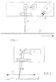
- Fig. 1 und 2
- schematische Ansichten der erfindungsgemäßen Meßanordnung,
- Fig. 3, 4
- jeweils einen gemessenen Profilverlauf quer zum Profil.
- 1 and 2
- schematic views of the measuring arrangement according to the invention,
- 3, 4
- one measured profile profile across the profile.
Das Prinzip der Triangulation ist grundsätzlich bekannt. Hierbei wird Licht einer Lichtquelle auf ein Meßobjekt ausgesandt, das von einer in einem Winkel zur Einfallsebene des ausgesandten Lichtstrahlenbündels angeordneten Kamera (oder sonstigem Target) beobachtet wird. Bestehende Profilhöhenunterschiede werden an unterschiedlichen Orten der Kamera abgebildet, wobei sich unter Berücksichtigung des Betrachtungswinkels und des Abbildungsmaßstabes das Höhenprofil ermitteln läßt.The principle of triangulation is generally known. Here, light from a light source is emitted onto a measurement object, which is observed by a camera (or other target) arranged at an angle to the plane of incidence of the emitted light beam. Existing profile height differences are imaged at different locations on the camera, the elevation profile being able to be determined taking into account the viewing angle and the imaging scale.
Bei der in Fig. 1 und 2 dargestellten Anordnung ist in einem gemeinsamen Gehäuse 10 ein Laser 11 angeordnet, dessen ausgesandtes Licht über einen schwenkbaren Spiegel 12 und eine Scanner-Linse 13 auf ein zu vermessendes Profil 20 abgebildet wird. Zur jeweiligen Drehwinkeleinstellung des Umlenkspiegels 12 dient ein Scanner 14. Das an dem Profil 20 reflektierte Licht wird mittels einer CCD-Kamera 15 aufgenommen. Je nach Drehwinkel des Scanner-Spiegels kann das Laserstrahlenbündel 16 den durch den Doppelpfeil überstrichenen Bereich 17 abtasten. Wie aus Fig. 2 ersichtlich, kann hierbei das Profil (das ist das Profil quer zur Transportrichtung 18) ermittelt werden. Betreffende Konturverläufe sind in Fig. 4 - und in vergrößerter Teilbereichs-Darstellung in Fig. 3 - zu entnehmen, in der insbesondere eine Referenzmarke 19 besonders gekennzeichnet ist, um eine örtliche Zuordnung treffen zu können.In the arrangement shown in FIGS. 1 and 2, a
In einem konkreten Anwendungsfall wird ein kollimierter Strahl einer Laserdiode über einen drehbaren Ablenkspiegel 12, der von einem Galvanometer-Scanner 14 angetrieben wird, auf eine Scanner-Optik 13 abgelenkt. Diese fokussiert den Laserstrahl 16 auf den Laufstreifen 20, wobei die gewählte spezielle Optik für eine konstante Laserspot-Geschwindigkeit über den gesamten Ablenkbereich, der größer als 500 mm sein kann, sorgt. Nahezu unabhängig vom Ablenkwinkel bleibt der gewählte Spotdurchmesser von 50 µm über den gesamten Ablenkbereich unverändert. Aufgrund des Breite/Höhe-Verhältnisses des Objektfeldes von 500 durch 25 (20 : 1) wird eine CCD-Kamera mit 2048 x 96 Bildpunkten eingesetzt, auf die die Lichtschnittfigur abgebildet wird. Hierdurch kann eine komplette Lichtschnittfigur auf ein einziges CCD-Chip abgebildet werden, so daß aufgrund der Anpassung des Kamera-Bildfeldes die auszuwertende Datenmenge auf ein Minimalmaß begrenzt ist. Die Belichtungszeit für die Aufnahme einer Lichtschnittfigur, d.h., einer Spur 17, beträgt 20 ms bei einer Abtastbreite von 500 mm.In a specific application, a collimated beam from a laser diode is deflected onto a scanner optic 13 via a
Die vorliegende Erfindung kann auch dergestalt angewendet werden, daß bei einem Laufstreifen sowohl die Ober- als auch Unterseite vermessen werden, wozu zwei Meßanordnungen gemäß Fig. 1 und 2 verwendet werden, die in spiegelsymmetrischem Aufbau zum Laufstreifen oberhalb und unterhalb dieses Laufstreifens 14 angeordnet sind. Durch punktweise Abstandsmessung mit zwei Triangulations-Vorrichtungen kann dann die Profildicke aus der Differenz der beiden Abstandswerte zusätzlich zu dem Profilverlauf ermittelt werden.The present invention can also be applied in such a way that both the top and bottom are measured in a tread, for which purpose two measuring arrangements according to FIGS. 1 and 2 are used, which are arranged in a mirror-symmetrical structure to the tread above and below this
Mit dem beschriebenen System kann eine Auflösung in vertikaler Richtung von zunächst 460 µm erreicht werden. Wird der auf den Laufstreifen geschrieben Spot nicht auf ein Pixel abgebildet, sondern über mehrere Pixel "verwaschen", kann mit Hilfe eines Subpixel-Algorithmus die Meßgenauigkeit auf 0,1 mm gesteigert werden. Die Auflösung in horizontaler Richtung beträgt 0,25 mm. Eine weitere Steigerung der geometrischen Auflösung des Profilmeßsystemes kann erreicht werden, wenn das Kamera-Bildfeld verkleinert wird, d.h., der Kameraabstand reduziert wird. Hierbei ist es allerdings notwendig, daß eine vertikale Nachführung der Kamera erforderlich wird.With the described system, a resolution in the vertical direction of initially 460 µm can be achieved. If the spot written on the tread is not mapped onto a pixel but "washed out" over several pixels, the measuring accuracy can be increased to 0.1 mm with the help of a sub-pixel algorithm. The resolution in the horizontal direction is 0.25 mm. A further increase in the geometric resolution of the profile measuring system can be achieved if the camera image field is reduced, i.e. the camera distance is reduced. Here, however, it is necessary that vertical tracking of the camera is necessary.
Die besonderen Vorteile der beschriebenen Vorrichtung und des beschriebenen Verfahrens liegen darin, daß pro Meßvorrichtung jeweils nur ein optisches Element, nämlich der Spiegel 12, bewegt werden muß. Das Laufstreifenprofil läßt sich mit nur einer einzigen Aufnahme komplett darstellen, wobei die Lichtschnittebene räumlich eindeutig definiert ist bzw. zugeordnet werden kann. Die Schwenkbarkeit des Spiegels 12 ermöglicht eine variable Einstellung der Spurbreite oder die Auswertung eines Profil-Teilbereiches.The particular advantages of the described device and the described method lie in the fact that only one optical element, namely the
Claims (19)
dadurch gekennzeichnet,
daß der Lichtschnitt in mehrere auf einer Linie liegende Punkte aufgeteilt ist, die nacheinander zum Zweck jeweiliger Reflektionsmessungen von einem fokussierten und unter verschiedenen Winkeln abgelenkten Laserstrahl abgetastet werden.Light section triangulation method for on-line measurement of moving profiles, in which laser light is directed onto a profile and the radiation reflected from the light section is recorded by means of a CCD camera arranged at an angle of preferably 45 ° to the direction of incidence,
characterized by
that the light section is divided into several points lying on a line, which are scanned successively for the purpose of respective reflection measurements by a focused laser beam deflected at different angles.
Applications Claiming Priority (2)
| Application Number | Priority Date | Filing Date | Title |
|---|---|---|---|
| DE4431922 | 1994-09-08 | ||
| DE19944431922 DE4431922A1 (en) | 1994-09-08 | 1994-09-08 | Light-section triangulation method and device for online measurement of moving profiles |
Publications (2)
| Publication Number | Publication Date |
|---|---|
| EP0701104A2 true EP0701104A2 (en) | 1996-03-13 |
| EP0701104A3 EP0701104A3 (en) | 1996-12-27 |
Family
ID=6527665
Family Applications (1)
| Application Number | Title | Priority Date | Filing Date |
|---|---|---|---|
| EP95112652A Withdrawn EP0701104A3 (en) | 1994-09-08 | 1995-08-11 | Laser sheet triangulation method and device for on-line measurement of moving profiles |
Country Status (2)
| Country | Link |
|---|---|
| EP (1) | EP0701104A3 (en) |
| DE (1) | DE4431922A1 (en) |
Cited By (4)
| Publication number | Priority date | Publication date | Assignee | Title |
|---|---|---|---|---|
| EP1788510A1 (en) | 2005-11-17 | 2007-05-23 | Mathias Reiter | Optical Braille lettering recognition |
| WO2008011866A1 (en) * | 2006-07-24 | 2008-01-31 | Jenoptik Laser, Optik, Systeme Gmbh | Optical system for surveying a surface |
| CN104296652A (en) * | 2014-02-27 | 2015-01-21 | 上海大学 | Optical measuring head based on discrete rotation trigonometry |
| US9513115B2 (en) | 2014-02-14 | 2016-12-06 | SmartRay GmbH | Method and apparatus for optical non-contact scanning of surfaces |
Families Citing this family (11)
| Publication number | Priority date | Publication date | Assignee | Title |
|---|---|---|---|---|
| DE19632696C1 (en) * | 1996-08-14 | 1998-04-23 | Thyssen Stahl Ag | Method and device for measuring the overlap width of an overlap joint of two workpieces lying flat on one another |
| DE19955709A1 (en) * | 1999-11-18 | 2001-05-31 | Fraunhofer Ges Forschung | Method and device for measuring the contour of an object surface using electromagnetic radiation |
| DE10134305B4 (en) * | 2000-07-18 | 2007-01-11 | Leuze Electronic Gmbh & Co Kg | Optoelectronic device |
| DE10055689B4 (en) * | 2000-11-06 | 2010-09-16 | Pepperl & Fuchs-Visolux Gmbh | Method for operating an optical triangulation light grid |
| DE10126086A1 (en) * | 2001-05-29 | 2002-12-05 | Sick Ag | Optoelectronic sensor |
| DE10246500A1 (en) * | 2002-10-04 | 2004-04-15 | Köberlein GmbH | Stamped part edge position determination method in which an optical arrangement is used to detect the narrow chamfered edge of stamped edge of the part with an optical arrangement of light source and sensor at right angles |
| DE10251574A1 (en) | 2002-11-06 | 2004-05-19 | Trützschler GmbH & Co KG | Device on a spinning preparation machine, e.g. Card, cleaner or the like, for measuring distances on cover sets |
| DE102006023745A1 (en) * | 2006-05-18 | 2008-01-17 | Scanware Electronic Gmbh | Method for detecting irregularities on a measured object |
| NL1033470C2 (en) | 2007-03-01 | 2008-09-02 | Vmi Epe Holland | Device for making a belt layer. |
| DE102017219559A1 (en) | 2017-11-03 | 2019-05-09 | Trumpf Laser- Und Systemtechnik Gmbh | Method for measuring a base element of a construction cylinder arrangement, with deflection of a measuring laser beam by a scanner optics |
| EP4000761A1 (en) | 2020-11-20 | 2022-05-25 | Primetals Technologies Austria GmbH | Contactless measuring of metal strands in a continuous casting plant |
Family Cites Families (10)
| Publication number | Priority date | Publication date | Assignee | Title |
|---|---|---|---|---|
| US4247204A (en) * | 1979-02-26 | 1981-01-27 | Intec Corporation | Method and apparatus for a web edge tracking flaw detection system |
| DE3315576A1 (en) * | 1983-04-29 | 1984-10-31 | Hommelwerke GmbH, 7730 Villingen-Schwenningen | Device for optical distance measurement, in particular for measuring profiles of workpieces or cutting edges of tools |
| DE3337251A1 (en) * | 1983-10-13 | 1985-04-25 | Gerd Dipl.-Phys. Dr. 8520 Erlangen Häusler | OPTICAL SCANING METHOD FOR THE THREE-DIMENSIONAL MEASUREMENT OF OBJECTS |
| DE4001298A1 (en) * | 1990-01-18 | 1991-07-25 | Nordischer Maschinenbau | METHOD FOR THREE-DIMENSIONAL LIGHT-OPTICAL MEASURING OF OBJECTS AND DEVICE FOR IMPLEMENTING THE METHOD |
| US5061062A (en) * | 1990-07-02 | 1991-10-29 | General Electric Company | Focus spot size controller for a variable depth range camera |
| DE4115445C2 (en) * | 1990-07-05 | 1994-02-17 | Reinhard Malz | Method for recording a three-dimensional image of an object according to the active triangulation principle and device therefor |
| DE4037383A1 (en) * | 1990-11-20 | 1992-05-21 | Mesacon Messtechnik | METHOD FOR CONTINUOUS TOUCH-FREE MEASUREMENT OF PROFILES AND DEVICE FOR CARRYING OUT THE MEASURING METHOD |
| JP2511391B2 (en) * | 1991-12-04 | 1996-06-26 | シーメンス アクチエンゲゼルシヤフト | Optical distance sensor |
| FR2698984B1 (en) * | 1992-12-04 | 1995-01-06 | Commissariat Energie Atomique | Method and device for acquiring a three-dimensional image of a small object by light probing and calibration means for implementing such an acquisition. |
| FR2700611B1 (en) * | 1993-01-18 | 1995-03-24 | Matra Sep Imagerie Inf | Method and device for dimensional control of the profile of long products. |
-
1994
- 1994-09-08 DE DE19944431922 patent/DE4431922A1/en not_active Withdrawn
-
1995
- 1995-08-11 EP EP95112652A patent/EP0701104A3/en not_active Withdrawn
Non-Patent Citations (1)
| Title |
|---|
| None |
Cited By (4)
| Publication number | Priority date | Publication date | Assignee | Title |
|---|---|---|---|---|
| EP1788510A1 (en) | 2005-11-17 | 2007-05-23 | Mathias Reiter | Optical Braille lettering recognition |
| WO2008011866A1 (en) * | 2006-07-24 | 2008-01-31 | Jenoptik Laser, Optik, Systeme Gmbh | Optical system for surveying a surface |
| US9513115B2 (en) | 2014-02-14 | 2016-12-06 | SmartRay GmbH | Method and apparatus for optical non-contact scanning of surfaces |
| CN104296652A (en) * | 2014-02-27 | 2015-01-21 | 上海大学 | Optical measuring head based on discrete rotation trigonometry |
Also Published As
| Publication number | Publication date |
|---|---|
| EP0701104A3 (en) | 1996-12-27 |
| DE4431922A1 (en) | 1996-05-23 |
Similar Documents
| Publication | Publication Date | Title |
|---|---|---|
| EP1606577B1 (en) | Method for contactlessly and dynamically detecting the profile of a solid body | |
| DE2810025C2 (en) | ||
| EP0701104A2 (en) | Laser sheet triangulation method and device for on-line measurement of moving profiles | |
| DE102005022095B4 (en) | Method and device for determining a lateral relative movement between a machining head and a workpiece | |
| DE19841235C5 (en) | Position calibration method for an optical measuring device | |
| EP0419936B1 (en) | Process and apparatus for the phase indication of radiation, especially light radiation | |
| DE3110287C2 (en) | ||
| DE2743054A1 (en) | OPTICAL MEASURING DEVICE WITH A LONGITUDINAL, FOCUSED BEAM | |
| EP0185167B1 (en) | Opto-electronic measuring process, apparatus therefor and its use | |
| EP0564535B1 (en) | Determination of the relative position of measurement points | |
| DE4212404A1 (en) | DEVICE FOR MEASURING THE SPATIAL FORM OF A LONG-STRETCHED COMPONENT | |
| DE102015217332A1 (en) | POSITION MEASURING DEVICE | |
| DE112004002986B4 (en) | Testing system for non-destructive material testing | |
| EP1901030A2 (en) | Measuring assembly and method for recording the surface of objects | |
| WO1992007234A1 (en) | Process and device for the optical measurement of the outlines of an opaque object | |
| DE3703505C2 (en) | ||
| DE3843470C2 (en) | ||
| CH695958A5 (en) | A method for adjusting a position of a measurement object in the film thickness measurement with X-ray fluorescence. | |
| EP3575741A1 (en) | Method for contact-free measurement of a workpiece edge | |
| DE3819058C2 (en) | ||
| DE3703504C2 (en) | ||
| DE2101689A1 (en) | Arrangement for carrying out a method for contactless optical testing and measuring of surfaces | |
| DE3532690A1 (en) | Method for measuring the surface roughness of workpieces, and an apparatus for carrying it out | |
| DE4121326C2 (en) | Orthogonal measuring method | |
| DE102017010108A1 (en) | Device and method for detecting the current position of a welding wire supplied to a laser welding process |
Legal Events
| Date | Code | Title | Description |
|---|---|---|---|
| PUAI | Public reference made under article 153(3) epc to a published international application that has entered the european phase |
Free format text: ORIGINAL CODE: 0009012 |
|
| AK | Designated contracting states |
Kind code of ref document: A2 Designated state(s): DE ES FR GB IT |
|
| PUAL | Search report despatched |
Free format text: ORIGINAL CODE: 0009013 |
|
| AK | Designated contracting states |
Kind code of ref document: A3 Designated state(s): DE ES FR GB IT |
|
| 17P | Request for examination filed |
Effective date: 19970627 |
|
| STAA | Information on the status of an ep patent application or granted ep patent |
Free format text: STATUS: THE APPLICATION IS DEEMED TO BE WITHDRAWN |
|
| 18D | Application deemed to be withdrawn |
Effective date: 19990302 |