EP1901030A2 - Measuring assembly and method for recording the surface of objects - Google Patents
Measuring assembly and method for recording the surface of objects Download PDFInfo
- Publication number
- EP1901030A2 EP1901030A2 EP07017869A EP07017869A EP1901030A2 EP 1901030 A2 EP1901030 A2 EP 1901030A2 EP 07017869 A EP07017869 A EP 07017869A EP 07017869 A EP07017869 A EP 07017869A EP 1901030 A2 EP1901030 A2 EP 1901030A2
- Authority
- EP
- European Patent Office
- Prior art keywords
- sensor
- mirror
- measuring
- detected
- measuring arrangement
- Prior art date
- Legal status (The legal status is an assumption and is not a legal conclusion. Google has not performed a legal analysis and makes no representation as to the accuracy of the status listed.)
- Withdrawn
Links
Images
Classifications
-
- G—PHYSICS
- G01—MEASURING; TESTING
- G01B—MEASURING LENGTH, THICKNESS OR SIMILAR LINEAR DIMENSIONS; MEASURING ANGLES; MEASURING AREAS; MEASURING IRREGULARITIES OF SURFACES OR CONTOURS
- G01B11/00—Measuring arrangements characterised by the use of optical techniques
- G01B11/24—Measuring arrangements characterised by the use of optical techniques for measuring contours or curvatures
-
- G—PHYSICS
- G01—MEASURING; TESTING
- G01N—INVESTIGATING OR ANALYSING MATERIALS BY DETERMINING THEIR CHEMICAL OR PHYSICAL PROPERTIES
- G01N21/00—Investigating or analysing materials by the use of optical means, i.e. using sub-millimetre waves, infrared, visible or ultraviolet light
- G01N21/84—Systems specially adapted for particular applications
- G01N21/88—Investigating the presence of flaws or contamination
- G01N21/95—Investigating the presence of flaws or contamination characterised by the material or shape of the object to be examined
- G01N21/952—Inspecting the exterior surface of cylindrical bodies or wires
Definitions
- the invention relates to a measuring arrangement for detecting the surface or parts of the surface of three-dimensionally extended objects by means of an optical sensor, wherein the sensor has a measuring range extending transversely to the optical axis of the sensor and wherein the object to be detected at least partially in the measuring range of the sensor located.
- the invention further relates to a corresponding method.
- the structure of the surface, the color, the color gradient or other properties of the surface are detected with an optical sensor.
- the results of the acquisition are converted into digital form, suitably reworked and stored.
- the detection can serve a variety of purposes. Thus, the determination of the profile of the surface, the recognition of individual structures on or in the surface, the measurement of the dimension of the object, the detection of production errors or the like in the foreground.
- the recognition of production errors is of great importance in the industrial context. If an error is detected, defective parts can be discarded early in a production chain or fed to a post-processing, before the errors lead to high costs or production losses, for example, in later production steps.
- the problem with such conditions of use is that the detection must provide information quickly and extremely reliably, without hindering the production and causing high costs of the production facility. For example, in the manufacture of pipes, profiled bars or continuous material, the product is moved past the sensor at a comparatively high speed. This requires the simultaneous detection of the surface at different locations around the circumference of the object.
- the present invention is therefore based on the object to design a measuring arrangement of the type mentioned and further, that the surface or parts of the surface of three-dimensionally extended objects reached as cost-effective and with simple design of the measuring arrangement even when detecting the surface over the entire circumference can be.
- a corresponding method, in particular for operating such a measuring arrangement, should be specified.
- the above object is solved by the features of claim 1.
- the measuring arrangement in question is developed such that the measuring arrangement comprises a mirror arrangement with one or more mirrors, wherein the mirror (s) of the mirror arrangement are arranged such that a part of the measuring area which passes the object to be detected unused, by the / the mirror is directed to the surface of the object to be detected.
- the above object is achieved by the features of claim 12. Thereafter, the method in question is characterized in that a part of the measuring range, which passes the object to be detected unused, is directed by means of a mirror arrangement on the surface of the object to be detected and thereby not directly detectable parts of the object are detected,
- the optical sensor is arranged such that the object to be detected uses only a part of the measuring range of the sensor transversely to the optical axis of the sensor.
- this is not a real limitation in many applications.
- the measuring arrangement according to the invention does not impose any restrictions as to how the ratio between the directly used measuring range and the measuring range used via the mirror arrangement must be.
- the ratio will be chosen such that a direct detection of the object is performed in the range of 40 to 70% of the measuring range.
- higher and lower percentages may be useful. So it may be useful for specially designed to be detected objects to capture the surface as vertical as possible. This can be achieved by the measuring arrangement according to the invention in that only a very small proportion of the available measuring range is used for the direct detection of the surface, while a much larger proportion is used for detecting the surface via the mirror arrangement.
- the sensor used in the measuring arrangement according to the invention is a distance sensor.
- This can be designed to capture two- or three-dimensional data.
- the sensor works according to the light-section method, in which a narrow and bright as possible Line is projected onto the project to be detected and the light beam reflected on the surface is detected by a detector array. From the displacement of the line in the detected image can be concluded on the three-dimensional nature of the surface.
- other distance sensors can be used instead of these so-called line triangulators.
- confocal, confocal chromatic and autofocus systems are noted.
- the detection of the surface can be done both pointwise and along any line or surface. At the same time, detection can take place both with and without displacement of the sensor or of the object to be detected relative to one another.
- the sensor has an opto-electrical detector, which can be designed as a line detector or matrix detector.
- the detector can be designed as a simple row of photodiodes, but could also comprise a CCD camera. In principle, all known from practice opto-electrical detectors can be used.
- a lighting device which illuminates the surface to be detected.
- This lighting device can be realized by a variety of known from practice light sources.
- the illumination source will be selected depending on the measurement method used.
- the illumination device comprises, for example, a line laser projector and is an integral part of the sensor system.
- the sensor could already have on its own a measuring range extending transversely to its optical axis.
- this extension of the measuring range could also be achieved by appropriate measures.
- the expansion of the measuring range could also be achieved by movement of the sensor transversely to its optical axis. Depending on the desired speed, with If the information is to be obtained by the sensor, a suitable means will be chosen here.
- the senor could be followed by suitable optics, for example a telecentric optic.
- the senor as a distance sensor further embodiments of the sensor are possible.
- the area of the surface which can be scanned simultaneously can be increased by the measuring arrangement according to the invention.
- the mirrors used could have a wide variety of geometrical configurations.
- the surface of the mirror is flat.
- the mirrors could also consist of sections of spheres, cylinders, ellipsoids, hyperboloids or the like. The choice of a suitable mirror surface will generally depend on the application situation.
- the mirror arrangement consists of several mirrors, then not all mirrors need to be executed in the same way. Rather, it is possible that differently configured mirrors are used in a mirror arrangement.
- a number of mirrors could be used in succession to guide the measuring area to the surface. Accordingly, a first mirror could not direct the measuring area to the surface of the object but instead to a second mirror, which could then direct the measuring area onto the object itself or another mirror.
- the mirrors may also be formed by a variety of reflective surfaces.
- metallised glass surfaces can be used as well as highly polished metal surfaces. In principle, all techniques known from practice can be used for this purpose.
- the mirror could be made movable. This movement could be translational, rotational or as a combination of both.
- the rotation and translation axes can be relatively arbitrarily oriented. Due to the mobility of the mirror, the measuring arrangement can be adapted to the respective object to be detected. The adaptation could also take place during the measuring process.
- the movement of the mirror can be done manually or automatically. With an automatic adjustment of the mirrors, the movement could be controlled by a control unit. This could ensure a traceable change in the mirror position and position.
- the measuring arrangement and the object to be detected could be designed to be displaceable relative to one another. It is insignificant whether a shift of the measuring arrangement or the object is made. It would also be conceivable to move both the measuring arrangement and the object. The direction of the movement is basically irrelevant. Here, the respective application will decide which approach makes sense. It would also be conceivable that the measuring arrangement is attached to a robot arm and, if necessary, is pivoted in the direction of the object to be detected.
- an image obtained by the sensor contains various components to be interpreted. So there are shares that reflect the surface itself. These result from the direct detection of the surface. In addition, however, shares are also available whose information can only be used clearly after a post-processing. These proportions result from the detection of the surface using the mirror assembly. A subsequent signal acquisition could separate these portions accordingly. If the sensor is a distance sensor, then the change between the areas detected directly and the areas detected via the mirror arrangement will manifest itself in a significant distance jump. This jump can then be used to separate the areas. Additionally or alternatively, knowledge about the geometry of the measuring arrangement could be used.
- the object to be detected appears behind the mirror. This manifests itself in the fact that a greater distance between the sensor and the object is determined than the distance between sensor and mirror would permit. If the distance of the sensor from a mirror surface is known, this information can be used to separate the portions of the sensor image. Since no measurement object can be detected behind the mirror, it is a fraction that has been detected by a mirror. In particular, when using other sensors may be necessary to use knowledge of the object to be detected.
- the signals of the sensor may need to be digitized by an analog-to-digital converter.
- analog-to-digital converter For this purpose, a variety of methods are known from practice. The signal processing itself could be done in suitable digital computers. There are also all known from practice computers available. By way of example only, reference may be made to the use of DSPs (Digital Signal Processor), microcontrollers, Field Programmable Gate Array (FPGA), Complex Programmable Logic Device (CPLD), Application Specific Integrated Circuit (ASIC), or combinations of these technologies. However, signal processing could also be performed on a PC with possibly additional hardware.
- DSPs Digital Signal Processor
- FPGA Field Programmable Gate Array
- CPLD Complex Programmable Logic Device
- ASIC Application Specific Integrated Circuit
- various information about the surface of the scanned object could be reconstructed. For example, an overall profile of the surface can be calculated using the geometric configuration of the measuring arrangement from a distance image of the sensor.
- the dimensions of the object or of individual areas of the object could also be determined. These dimensions may include, for example, the thickness of the object.
- the information obtained by the sensor could be used to find specific locations on the object. These locations may include, for example, manufacturing defects in an object or special markings.
- the measuring arrangement according to the invention can also be used multiple times.
- the measuring arrangement can be used multiple times to detect an object along its circumference.
- the number of required sensors can be significantly reduced by the enlarged on the surface simultaneously detectable by a sensor area.
- the number of control units needed to control the individual sensors and the necessary additional equipment such as analog-to-digital converters is reduced.
- the signal processing can be done more rational and cheaper.
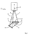
- FIG. 1 shows a measuring arrangement 1 according to the invention for detecting the surface 2 of an object 3 by means of a sensor 4.
- the sensor 4 has a measuring area extending transversely to its optical axis 5, whose edge beams are given by the light beams 6 and 7.
- Another light beam 8 in the measuring range is shown in FIG. 1 between the marginal rays 6, 7.
- Light beam 8 characterizes the light beam that just passes the object 3.
- the illuminating rays located between the light beams 7 and 8 are reflected by the surface 2 of the object 3 and impinge on a detector of the sensor 4 Light rays thus serve the direct detection of the surface.
- the light rays between the light beams 6 and 8 pass through the object 3 and would be lost unused in measuring arrangements known from the prior art.
- a mirror 9 which directs the passing light rays back onto the object 3. These illumination light beams are then reflected by the surface 2 of the object 3 and reflected again via mirror 9. From here they enter the detector of the sensor 4. The light rays located between the light beams 6 and 8 thus serve for the indirect detection of the surface.
- the unused measuring range of the sensor can be used by the measuring arrangement according to the invention on the one hand.
- the otherwise undetectable underside of the object 3 can be detected. From the information obtained in this way, properties of the surface 2 of the object 3 can be reconstructed.
- the sensor 4 used is a distance sensor, the profile of the top and bottom of the object 3 can be reconstructed.
- the thickness d of the object 3 can be determined.
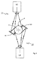
- Fig. 2 shows the detection of the surface 2 of an object 3 over its entire circumference.
- the detected object 3 may, for example, be a tube which is to be examined after production and moves perpendicular to the plane of the drawing in FIG.
- the measuring arrangement shown in FIG. 1 is used in duplicate, wherein the two measuring arrangements are rotated by 180 °.
- a sensor 4.1 or 4.2 in turn illuminates the surface 2 of an object 3.
- the light rays illuminate the object 3 directly to a part, to another part they are directed to the surface 2 of the object 3 via a mirror 9.1 or 9.2.
- FIG. 2 clearly shows that, by using the measuring arrangement according to the invention, the surface 2 of the object 3 can be detected over the entire circumference.
- the number of sensors used can be reduced to two by the measuring arrangement according to the invention. Nevertheless, the entire circumference of the object 3 is detectable.
Abstract
Description
Die Erfindung betrifft eine Messanordnung zum Erfassen der Oberfläche oder Teile der Oberfläche von dreidimensional ausgedehnten Objekten mittels eines optischen Sensors, wobei der Sensor einen sich quer zu der optischen Achse des Sensors erstreckenden Messbereich aufweist und wobei sich das zu erfassende Objekt zumindest teilweise im Messbereich des Sensors befindet. Die Erfindung betrifft ferner ein entsprechendes Verfahren.The invention relates to a measuring arrangement for detecting the surface or parts of the surface of three-dimensionally extended objects by means of an optical sensor, wherein the sensor has a measuring range extending transversely to the optical axis of the sensor and wherein the object to be detected at least partially in the measuring range of the sensor located. The invention further relates to a corresponding method.
Es besteht häufig die Notwendigkeit, die Oberfläche oder Teile der Oberfläche von Objekten zu erfassen. Dabei wird die Struktur der Oberfläche, die Farbe, der Farbverlauf oder andere Eigenschaften der Oberfläche mit einem optischen Sensor erfasst. Meist werden die Ergebnisse der Erfassung in digitale Form umgewandelt, geeignet nachbearbeitet und abgespeichert. Die Erfassung kann den verschiedensten Zwecken dienen. So kann das Bestimmen des Profils der Oberfläche, das Erkennen einzelner Strukturen auf oder in der Oberfläche, das Vermessen der Dimension des Objekts, das Erkennen von Produktionsfehlern oder dergleichen im Vordergrund stehen.There is often a need to capture the surface or parts of the surface of objects. The structure of the surface, the color, the color gradient or other properties of the surface are detected with an optical sensor. In most cases, the results of the acquisition are converted into digital form, suitably reworked and stored. The detection can serve a variety of purposes. Thus, the determination of the profile of the surface, the recognition of individual structures on or in the surface, the measurement of the dimension of the object, the detection of production errors or the like in the foreground.
Insbesondere das Erkennen von Produktionsfehlern ist im industriellen Kontext von großer Bedeutung. Bei Erkennen eines Fehlers können fehlerhafte Teile frühzeitig in einer Fertigungskette ausgesondert oder einer Nachbearbeitung zugeführt werden, bevor die Fehler beispielsweise in späteren Fertigungsschritten zu hohen Kosten oder Produktionsausfällen führen. Problematisch bei derartigen Einsatzbedingungen ist, dass die Erfassung schnell und äußerst zuverlässig Informationen liefern muss, ohne die Fertigung zu behindern und hohe Kosten der Fertigungsanlage hervorzurufen. Beispielsweise bei der Herstellung von Rohren, Profilstäben oder Stranggut wird das Erzeugnis mit vergleichsweise hoher Geschwindigkeit an dem Sensor vorbeibewegt. Dies erfordert eine möglichst zeitgleiche Erfassung der Oberfläche an verschiedenen Stellen um den Umfang des Objekts herum.In particular, the recognition of production errors is of great importance in the industrial context. If an error is detected, defective parts can be discarded early in a production chain or fed to a post-processing, before the errors lead to high costs or production losses, for example, in later production steps. The problem with such conditions of use is that the detection must provide information quickly and extremely reliably, without hindering the production and causing high costs of the production facility. For example, in the manufacture of pipes, profiled bars or continuous material, the product is moved past the sensor at a comparatively high speed. This requires the simultaneous detection of the surface at different locations around the circumference of the object.
Aus der Praxis bekannte Ansätze zur Erfassung der Oberfläche, bei denen ein Sensor entlang der Oberfläche des zu erfassenden Objekts bewegt wird und die Oberfläche sukzessive abscannt, sind in diesen Fällen nicht anwendbar. Daher besteht die Notwendigkeit, mehrere Sensoren geschickt zu platzieren, um möglichst die gesamte Oberfläche oder zumindest die interessanten Teile der Oberfläche gleichzeitig erfassen zu können. Hier werden häufig vier und mehr Sensoren um das abzutastende Objekt angeordnet und deren Messergebnisse in einer Signalverarbeitung zu einem Gesamtbild der Oberfläche des Objekts zusammengeführt. Die Anzahl der verwendeten Sensoren ist im Allgemeinen von der Komplexität der abzutastenden Oberfläche abhängig. Je komplizierter die Oberfläche ausgestaltet ist, desto mehr Sensoren werden notwendig. Da die in diesem Zusammenhang eingesetzten optischen Sensoren vergleichsweise teuer sind, entstehen erhebliche Kosten beim Aufbau der Fertigungsanlagen. Zudem muss für jeden Sensor die entsprechende Hardware zum Ansteuern des Sensors und zur Signalverarbeitung zur Verfügung stehen.Practically known approaches for detecting the surface, in which a sensor is moved along the surface of the object to be detected and the surface is scanned successively, are not applicable in these cases. Therefore, there is a need to place several sensors skillfully to be able to capture as much as possible the entire surface or at least the interesting parts of the surface simultaneously. Here are often four or more sensors to be scanned Object arranged and their measurement results combined in a signal processing to form an overall image of the surface of the object. The number of sensors used is generally dependent on the complexity of the surface to be scanned. The more complicated the surface is designed, the more sensors will be needed. Since the optical sensors used in this context are relatively expensive, there are considerable costs in the construction of the production facilities. In addition, the corresponding hardware for activating the sensor and for signal processing must be available for each sensor.
Der vorliegenden Erfindung liegt daher die Aufgabe zugrunde, eine Messanordnung der eingangs genannten Art derart auszugestalten und weiterzubilden, dass die Oberfläche oder Teile der Oberfläche von dreidimensional ausgedehnten Objekten auch bei dem Erfassen der Oberfläche über den gesamten Umfang möglichst kostengünstig und bei einfacher Konstruktion der Messanordnung erreicht werden kann. Ein entsprechendes Verfahren, insbesondere zum Betreiben einer derartigen Messanordnung, soll angegeben werden.The present invention is therefore based on the object to design a measuring arrangement of the type mentioned and further, that the surface or parts of the surface of three-dimensionally extended objects reached as cost-effective and with simple design of the measuring arrangement even when detecting the surface over the entire circumference can be. A corresponding method, in particular for operating such a measuring arrangement, should be specified.
Erfindungsgemäß wird die voranstehende Aufgabe durch die Merkmale des Patentanspruchs 1 gelöst. Danach ist die in Rede stehende Messanordnung derart weitergebildet, dass die Messanordnung eine Spiegelanordnung mit einem oder mehreren Spiegeln umfasst, wobei der/die Spiegel der Spiegelanordnung derart angeordnet sind, dass ein Teil des Messbereichs, der das zu erfassende Objekt ungenutzt passiert, durch den/die Spiegel auf die Oberfläche des zu erfassenden Objekts gelenkt wird.According to the invention the above object is solved by the features of
In verfahrensmäßiger Hinsicht wird die voranstehende Aufgabe durch die Merkmale des Patentanspruchs 12 gelöst. Danach ist das in Rede stehende Verfahren dadurch gekennzeichnet, dass ein Teil des Messbereichs, der das zu erfassende Objekt ungenutzt passiert, mittels einer Spiegelanordnung auf die Oberfläche des zu erfassenden Objekts gelenkt wird und dadurch nicht direkt erfassbare Teile des Objekts erfassbar werden,In procedural terms, the above object is achieved by the features of claim 12. Thereafter, the method in question is characterized in that a part of the measuring range, which passes the object to be detected unused, is directed by means of a mirror arrangement on the surface of the object to be detected and thereby not directly detectable parts of the object are detected,
In erfindungsgemäßer Weise ist zunächst erkannt worden, dass insbesondere beim Einsatz von vier und mehr Sensoren in vielen Anwendungsfällen lediglich ein geringer Teil des Messbereichs der einzelnen Sensoren quer zu deren optischer Achse genutzt wird. In erfindungsgemäßer Weise ist ferner erkannt worden, dass gerade dieser üblicherweise als negativ empfundene Effekt bei der Verbesserung der Messanordnung genutzt werden kann. Dazu sind lediglich einfache konstruktive Maßnahmen notwendig. Es wird nämlich erfindungsgemäß zu der Messanordnung eine Spiegelanordnung mit einem oder mehreren Spiegeln hinzugefügt, mit der der Teil des Messbereichs, der das zu erfassende Objekt ungenutzt passiert, nutzbar gemacht wird. Die Spiegel sind dabei derart angeordnet, dass der sonst ungenutzt passierende Teil des Messbereichs auf die Oberfläche des zu erfassenden Objekts reflektiert wird. Dadurch wird bei geeigneter Anordnung des/der Spiegel die gleichzeitige Erfassung weiterer Bereiche der Oberfläche, die sonst nicht erfassbar wären, mit nur einem Sensor ermöglicht. Dies hat zur Folge, dass auf einfachste Art und Weise die zur Erfassung einer Oberfläche oder eines gewünschten Teils einer Oberfläche notwendige Anzahl von Sensoren reduziert werden kann. Voraussetzung ist, dass der optische Sensor derart angeordnet ist, dass das zu erfassende Objekt lediglich einen Teil des Messbereichs des Sensors quer zur optischen Achse des Sensors nutzt. Dies stellt in vielen Anwendungsfällen jedoch keine echte Einschränkung dar.In accordance with the invention, it has first been recognized that, in particular in the use of four and more sensors, in many applications only a small one Part of the measuring range of the individual sensors is used transversely to the optical axis. In accordance with the invention, it has also been recognized that it is precisely this effect, which is usually perceived as negative, that can be used to improve the measuring arrangement. For this purpose, only simple design measures are necessary. In fact, according to the invention, a mirror arrangement with one or more mirrors is added to the measuring arrangement with which the part of the measuring area which passes the object to be detected unused is made usable. The mirrors are arranged such that the otherwise unused passing part of the measuring range is reflected onto the surface of the object to be detected. As a result, with a suitable arrangement of the / the mirror, the simultaneous detection of other areas of the surface, which would otherwise not be detected, possible with only one sensor. As a result, the number of sensors required to detect a surface or a desired part of a surface can be reduced in the simplest manner. The prerequisite is that the optical sensor is arranged such that the object to be detected uses only a part of the measuring range of the sensor transversely to the optical axis of the sensor. However, this is not a real limitation in many applications.
Prinzipiell legt die erfindungsgemäße Messanordnung keine Einschränkungen auf, wie das Verhältnis zwischen direkt genutztem Messbereich und über die Spiegelanordnung genutztem Messbereich sein muss. In vielen Fällen wird das Verhältnis derart gewählt sein, dass im Bereich von 40 bis 70% des Messbereichs eine direkte Erfassung des Objekts durchgeführt wird. Allerdings können auch höhere und niedrigere Prozentzahlen sinnvoll sein. So kann es bei besonders ausgestalteten zu erfassenden Objekten sinnvoll sein, die Oberfläche möglichst senkrecht zu erfassen. Dies kann durch die erfindungsgemäße Messanordnung dadurch erreicht werden, dass lediglich ein sehr geringer Anteil des verfügbaren Messbereiches zur direkten Erfassung der Oberfläche genutzt wird, während ein weitaus größerer Anteil zur Erfassung der Oberfläche über die Spiegelanordnung genutzt wird.In principle, the measuring arrangement according to the invention does not impose any restrictions as to how the ratio between the directly used measuring range and the measuring range used via the mirror arrangement must be. In many cases, the ratio will be chosen such that a direct detection of the object is performed in the range of 40 to 70% of the measuring range. However, higher and lower percentages may be useful. So it may be useful for specially designed to be detected objects to capture the surface as vertical as possible. This can be achieved by the measuring arrangement according to the invention in that only a very small proportion of the available measuring range is used for the direct detection of the surface, while a much larger proportion is used for detecting the surface via the mirror arrangement.
Vorzugsweise handelt es sich bei dem in der erfindungsgemäßen Messanordnung eingesetzten Sensor um einen Abstandssensor. Dieser kann zur Erfassung von zwei- oder dreidimensionalen Daten ausgebildet sein. Vorzugsweise arbeitet der Sensor nach dem Lichtschnittverfahren, bei dem eine möglichst schmale und helle Linie auf das zu erfassende Projekt projiziert wird und der an der Oberfläche reflektierte Lichtstrahl durch ein Detektorarray detektiert wird. Aus der Verschiebung der Linie in dem detektierten Bild kann auf die dreidimensionale Beschaffenheit der Oberfläche geschlossen werden. Statt dieser so genannten Linientriangulatoren können jedoch auch andere Abstandssensoren verwendet werden. Lediglich beispielhaft sei auf konfokale, konfokal-chromatisch messende und Autofokussysteme hingewiesen. Dabei kann die Erfassung der Oberfläche sowohl punktweise als auch entlang einer beliebig gearteten Linie oder Fläche erfolgen. Gleichzeitig kann eine Erfassung sowohl mit als auch ohne Verschiebung des Sensors oder des zu erfassenden Objekts relativ zueinander erfolgen.Preferably, the sensor used in the measuring arrangement according to the invention is a distance sensor. This can be designed to capture two- or three-dimensional data. Preferably, the sensor works according to the light-section method, in which a narrow and bright as possible Line is projected onto the project to be detected and the light beam reflected on the surface is detected by a detector array. From the displacement of the line in the detected image can be concluded on the three-dimensional nature of the surface. However, other distance sensors can be used instead of these so-called line triangulators. By way of example only, confocal, confocal chromatic and autofocus systems are noted. In this case, the detection of the surface can be done both pointwise and along any line or surface. At the same time, detection can take place both with and without displacement of the sensor or of the object to be detected relative to one another.
Der Sensor weist einen optoelektrischen Detektor auf, der als Zeilendetektor oder Matrixdetektor ausgebildet sein kann. Der Detektor kann als einfache Fotodiodenzeile ausgebildet sein, könnte jedoch auch eine CCD-Kamera umfassen. Prinzipiell sind sämtliche aus der Praxis bekannten optoelektrischen Detektoren einsetzbar.The sensor has an opto-electrical detector, which can be designed as a line detector or matrix detector. The detector can be designed as a simple row of photodiodes, but could also comprise a CCD camera. In principle, all known from practice opto-electrical detectors can be used.
Vorzugsweise ist eine Beleuchtungseinrichtung vorhanden, die die zu erfassende Oberfläche beleuchtet. Diese Beleuchtungseinrichtung kann durch die verschiedensten aus der Praxis bekannten Lichtquellen realisiert sein. Lediglich beispielhaft sei auf die Verwendung eines Laserlinienprojektors, eines Punktlasers, einer Halogenlampe, einer Xenonlampe oder LEDs verwiesen. Im Allgemeinen wird die Beleuchtungsquelle in Abhängigkeit des verwendeten Messverfahrens ausgewählt werden. Bei dem zuvor beschriebenen, nach dem Linienschnittverfahren arbeitenden Abstandssensor umfasst die Beleuchtungseinrichtung beispielsweise einen Linienlaserprojektor und ist integraler Bestandteil des Sensorsystems.Preferably, a lighting device is present, which illuminates the surface to be detected. This lighting device can be realized by a variety of known from practice light sources. By way of example only, reference may be made to the use of a laser line projector, a spot laser, a halogen lamp, a xenon lamp or LEDs. In general, the illumination source will be selected depending on the measurement method used. In the above-described distance sensor operating according to the line cutting method, the illumination device comprises, for example, a line laser projector and is an integral part of the sensor system.
Der Sensor könnte bereits von sich aus einen sich quer zu seiner optischen Achse erstreckenden Messbereich aufweisen. Allerdings könnte diese Ausdehnung des Messbereichs auch durch geeignete Maßnahmen erreicht werden. Beispielhaft sei auf die Verwendung einer Linse, eines Linsensystems oder einer Umlenkvorrichtung, die beispielsweise einen die Oberfläche abtastenden Laserlichtstrahl über die Oberfläche des zu erfassenden Gegenstands führt, verwiesen. Andererseits könnte die Ausdehnung des Messbereichs auch durch Bewegung des Sensors quer zu dessen optischer Achse erzielt werden. Je nach gewünschter Geschwindigkeit, mit der die Informationen durch den Sensor gewonnen werden sollen, wird hier ein geeignetes Mittel zu wählen sein.The sensor could already have on its own a measuring range extending transversely to its optical axis. However, this extension of the measuring range could also be achieved by appropriate measures. By way of example, reference is made to the use of a lens, a lens system or a deflecting device which, for example, guides a laser light beam scanning the surface over the surface of the object to be detected. On the other hand, the expansion of the measuring range could also be achieved by movement of the sensor transversely to its optical axis. Depending on the desired speed, with If the information is to be obtained by the sensor, a suitable means will be chosen here.
Zum Erreichen eines ausreichend großen Messbereichs in Richtungen längs der optischen Achse könnte dem Sensor eine geeignete Optik, beispielsweise eine telezentrische Optik, nachgeschaltet sein.To achieve a sufficiently large measuring range in directions along the optical axis, the sensor could be followed by suitable optics, for example a telecentric optic.
Neben einer Ausgestaltung des Sensors als Abstandssensor sind weitere Ausgestaltungen des Sensors möglich. Lediglich beispielhaft sei auf die Verwendung einer CCD-/CMOS-Kamera mit zugeordneter Beleuchtungseinrichtung verwiesen, die die Farbe und/oder Struktur des Objekts erfasst. Auch hier kann durch die erfindungsgemäße Messanordnung der gleichzeitig abtastbare Bereich der Oberfläche vergrößert werden.In addition to an embodiment of the sensor as a distance sensor further embodiments of the sensor are possible. By way of example only, reference may be made to the use of a CCD / CMOS camera with associated illumination device which detects the color and / or structure of the object. Here too, the area of the surface which can be scanned simultaneously can be increased by the measuring arrangement according to the invention.
Die eingesetzten Spiegel könnten die verschiedensten geometrischen Ausgestaltungen aufweisen. In der einfachsten Form ist die Oberfläche des Spiegels plan. Dadurch wird eine Rekonstruktion der Oberfläche besonders einfache erfolgen können. Allerdings könnten die Spiegel auch aus Ausschnitten aus Kugeln, Zylindern, Ellipsoiden, Hyperboloiden oder dergleichen bestehen. Die Wahl einer geeigneten Spiegeloberfläche wird im Allgemeinen von der Anwendungssituation abhängen.The mirrors used could have a wide variety of geometrical configurations. In the simplest form, the surface of the mirror is flat. As a result, a reconstruction of the surface can be done very easily. However, the mirrors could also consist of sections of spheres, cylinders, ellipsoids, hyperboloids or the like. The choice of a suitable mirror surface will generally depend on the application situation.
Besteht die Spiegelanordnung aus mehreren Spiegeln, so müssen nicht alle Spiegel auf gleiche Art und Weise ausgeführt sein. Vielmehr ist es möglich, dass verschieden ausgestaltete Spiegel in einer Spiegelanordnung Verwendung finden.If the mirror arrangement consists of several mirrors, then not all mirrors need to be executed in the same way. Rather, it is possible that differently configured mirrors are used in a mirror arrangement.
Darüber hinaus könnte zur Lenkung des Messbereichs auf die Oberfläche auch eine Reihe von mehreren Spiegeln in Folge eingesetzt werden. Ein erster Spiegel könnte demnach den Messbereich nicht auf die Oberfläche des Objekts sondern stattdessen auf einen zweiten Spiegel lenken, Dieser könnte dann den Messbereich auf das Objekt selbst oder einen weiteren Spiegel lenken.In addition, a number of mirrors could be used in succession to guide the measuring area to the surface. Accordingly, a first mirror could not direct the measuring area to the surface of the object but instead to a second mirror, which could then direct the measuring area onto the object itself or another mirror.
Die Spiegel können ebenso durch die verschiedensten reflektierenden Oberflächen gebildet sein. So können metallisierte Glasflächen ebenso Verwendung finden wie hochfein polierte Metalloberflächen. Hierzu sind prinzipiell sämtliche aus der Praxis bekannten Techniken einsetzbar.The mirrors may also be formed by a variety of reflective surfaces. For example, metallised glass surfaces can be used as well as highly polished metal surfaces. In principle, all techniques known from practice can be used for this purpose.
Zum Erzielen einer möglichst flexiblen Messanordnung könnten die Spiegel bewegbar ausgestaltet sein. Diese Bewegung könnte translatorisch, rotatorisch oder als eine Kombination von beiden erfolgen. Die Rotations- und Translationsachsen können relativ beliebig orientiert sein. Durch die Bewegbarkeit der Spiegel kann die Messanordnung an das jeweils zu erfassende Objekt angepasst werden. Die Anpassung könnte auch während des Messvorgangs erfolgen. Die Bewegung der Spiegel kann dabei manuell oder automatisch erfolgen. Bei einer automatischen Verstellung der Spiegel könnte die Bewegung durch ein Steuergerät gesteuert werden. Dadurch könnte eine nachvollziehbare Veränderung der Spiegellage und Position gewährleistet werden.To achieve a flexible measuring arrangement as possible, the mirror could be made movable. This movement could be translational, rotational or as a combination of both. The rotation and translation axes can be relatively arbitrarily oriented. Due to the mobility of the mirror, the measuring arrangement can be adapted to the respective object to be detected. The adaptation could also take place during the measuring process. The movement of the mirror can be done manually or automatically. With an automatic adjustment of the mirrors, the movement could be controlled by a control unit. This could ensure a traceable change in the mirror position and position.
Zur Erfassung des gesamten zu erfassenden Bereichs könnten die Messanordnung und das zu erfassende Objekt relativ zueinander verschiebbar ausgestaltet sein. Es ist dabei unbedeutend, ob eine Verschiebung der Messanordnung oder des Objekts vorgenommen wird. Es wäre auch eine Bewegung sowohl der Messanordnung als auch des Objekts denkbar. Auch die Richtung der Bewegung ist prinzipiell unerheblich. Hier wird der jeweilige Anwendungsfall entscheiden, welche Vorgehensweise sinnvoll ist. Es wäre zudem denkbar, dass die Messanordnung an einen Roboterarm angebracht ist und im Bedarfsfall in Richtung des zu erfassenden Objekts geschwenkt wird.For detecting the entire area to be detected, the measuring arrangement and the object to be detected could be designed to be displaceable relative to one another. It is insignificant whether a shift of the measuring arrangement or the object is made. It would also be conceivable to move both the measuring arrangement and the object. The direction of the movement is basically irrelevant. Here, the respective application will decide which approach makes sense. It would also be conceivable that the measuring arrangement is attached to a robot arm and, if necessary, is pivoted in the direction of the object to be detected.
Durch die Verwendung der Spiegelanordnung zum Erfassen der Oberfläche oder Teile der Oberfläche eines Objekts enthält ein durch den Sensor gewonnenes Bild verschieden zu interpretierende Anteile. So sind Anteile vorhanden, die die Oberfläche selbst wiedergeben. Diese resultieren aus der direkten Erfassung der Oberfläche. Daneben sind jedoch auch Anteile vorhanden, deren Informationen erst nach einer Nachbearbeitung eindeutig verwendbar sind. Diese Anteile resultieren von der Erfassung der Oberfläche unter Verwendung der Spiegelanordnung. Eine der Erfassung nachfolgende Signalverarbeitung könnte diese Anteile entsprechend trennen. Handelt es sich bei dem Sensor um einen Abstandssensor, so wird sich der Wechsel zwischen den direkt und den über die Spiegelanordnung erfassten Bereichen in einem deutlichen Abstandssprung äußern. Dieser Sprung kann dann zur Trennung der Bereiche verwendet werden. Zusätzlich oder alternativ könnte Wissen über die Geometrie der Messanordnung Verwendung finden. So ist es beispielsweise möglich, dass bei der Verwendung eines Abstandssensors das zu erfassende Objekt hinter dem Spiegel erscheint. Dies äußert sich darin, dass ein größerer Abstand zwischen Sensor und Objekt bestimmt wird, als der Abstand zwischen Sensor und Spiegel zulassen würde. Ist der Abstand des Sensors von einer Spiegelfläche bekannt, kann diese Information zum Trennen der Anteile des Sensorbildes genutzt werden. Da kein Messobjekt hinter dem Spiegel erfasst werden kann, handelt es sich um einen Anteil, der über einen Spiegel erfasst wurde. Insbesondere bei der Verwendung anderer Sensoren kann eventuell die Verwendung von Wissen über das zu erfassende Objekt notwendig sein.Through the use of the mirror arrangement for detecting the surface or parts of the surface of an object, an image obtained by the sensor contains various components to be interpreted. So there are shares that reflect the surface itself. These result from the direct detection of the surface. In addition, however, shares are also available whose information can only be used clearly after a post-processing. These proportions result from the detection of the surface using the mirror assembly. A subsequent signal acquisition could separate these portions accordingly. If the sensor is a distance sensor, then the change between the areas detected directly and the areas detected via the mirror arrangement will manifest itself in a significant distance jump. This jump can then be used to separate the areas. Additionally or alternatively, knowledge about the geometry of the measuring arrangement could be used. So it is possible, for example, that when using a distance sensor, the object to be detected appears behind the mirror. This manifests itself in the fact that a greater distance between the sensor and the object is determined than the distance between sensor and mirror would permit. If the distance of the sensor from a mirror surface is known, this information can be used to separate the portions of the sensor image. Since no measurement object can be detected behind the mirror, it is a fraction that has been detected by a mirror. In particular, when using other sensors may be necessary to use knowledge of the object to be detected.
Vor einer Signalverarbeitung müssen die Signale des Sensors gegebenenfalls durch einen Analog-Digital-Wandler digitalisiert werden. Hierzu sind aus der Praxis die verschiedensten Verfahren bekannt. Die Signalverarbeitung selbst könnte in geeigneten Digitalrechnern vorgenommen werden. Dazu stehen ebenso sämtliche aus der Praxis bekannten Rechner zur Verfügung. Lediglich beispielhaft sei auf den Einsatz von DSPs (Digitale Signalprozessor), Mikrocontroller, FPGAs (Field Programmable Gate Array), CPLD (Complex Programmable Logic Device), ASICs (Application Specific Integrated Circuit) oder Kombinationen dieser Technologien hingewiesen. Allerdings könnte eine Signalverarbeitung auch auf einem PC mit eventuell zusätzlicher Hardware durchgeführt werden.Before signal processing, the signals of the sensor may need to be digitized by an analog-to-digital converter. For this purpose, a variety of methods are known from practice. The signal processing itself could be done in suitable digital computers. There are also all known from practice computers available. By way of example only, reference may be made to the use of DSPs (Digital Signal Processor), microcontrollers, Field Programmable Gate Array (FPGA), Complex Programmable Logic Device (CPLD), Application Specific Integrated Circuit (ASIC), or combinations of these technologies. However, signal processing could also be performed on a PC with possibly additional hardware.
Aus den durch den Sensor gewonnenen und eventuell aufbereiteten Informationen könnten verschiedene Informationen über die Oberfläche des abgetasteten Objekts rekonstruiert werden. So kann beispielsweise unter Verwendung der geometrischen Ausgestaltung der Messanordnung aus einem Abstandsbild des Sensors ein Gesamtprofil der Oberfläche errechnet werden. Andererseits könnten auch die Abmessungen des Objekts oder einzelner Bereiche des Objekts bestimmt werden. Diese Abmessungen können beispielsweise die Dicke des Objekts umfassen. Ferner könnten die durch den Sensor gewonnenen Informationen dazu genutzt werden, um bestimmte Stellen an dem Objekt zu finden. Diese Stellen können beispielsweise Herstellungsfehler bei einem Objekt oder besondere Markierungen umfassen.From the information obtained and possibly processed by the sensor, various information about the surface of the scanned object could be reconstructed. For example, an overall profile of the surface can be calculated using the geometric configuration of the measuring arrangement from a distance image of the sensor. On the other hand, the dimensions of the object or of individual areas of the object could also be determined. These dimensions may include, for example, the thickness of the object. Furthermore, the information obtained by the sensor could be used to find specific locations on the object. These locations may include, for example, manufacturing defects in an object or special markings.
Ähnlich wie bei den aus der Praxis bekannten Messanordnungen zum Erfassen der Oberfläche eines Objekts kann auch die erfindungsgemäße Messanordnung mehrfach eingesetzt: werden. So kann zur Erfassung eines Objekts entlang seines Umfangs die Messanordnung mehrfach eingesetzt werden. Im Gegensatz zu den aus der Praxis bekannten Anordnungen ist durch den vergrößerten durch einen Sensor gleichzeitig erfassbaren Bereich auf der Oberfläche die Zahl der benötigten Sensoren erheblich reduzierbar. Durch die Reduzierung der benötigten Sensoren reduziert sich auch die Anzahl der benötigten Steuergeräte zum Ansteuern der einzelnen Sensoren sowie der notwendigen Zusatzgeräte wie beispielsweise Analog-Digital-Wandler. Auch die Signalnachbearbeitung kann rationeller und günstiger erfolgen. Durch all diese Effekte reduziert sich verständlicherweise auch die Baugröße der gesamten Anordnung, wodurch die Anordnung beispielsweise wesentlich einfacher in eine Fertigungsanlage einbaubar wird.Similar to the measuring arrangements known from practice for detecting the surface of an object, the measuring arrangement according to the invention can also be used multiple times. Thus, the measuring arrangement can be used multiple times to detect an object along its circumference. Unlike the out known arrangements in practice, the number of required sensors can be significantly reduced by the enlarged on the surface simultaneously detectable by a sensor area. By reducing the required sensors, the number of control units needed to control the individual sensors and the necessary additional equipment such as analog-to-digital converters is reduced. The signal processing can be done more rational and cheaper. By all these effects understandably reduces the size of the entire arrangement, making the arrangement, for example, much easier to install in a manufacturing plant.
Es gibt nun verschiedene Möglichkeiten, die Lehre der vorliegenden Erfindung in vorteilhafter Weise auszugestalten und weiterzubilden. Dazu ist einerseits auf die den Patentansprüchen 1 und 12 jeweils nachgeordneten Patentansprüche und andererseits auf die nachfolgende Erläuterung eines bevorzugten Ausführungsbeispiels der Erfindung anhand der Zeichnung zu verweisen. In Verbindung mit der Erläuterung des bevorzugten Ausführungsbeispiels der Erfindung anhand der Zeichnung werden auch im Allgemeinen bevorzugte Ausgestaltungen und Weiterbildungen der Lehre erläutert. In der Zeichnung zeigen
- Fig. 1
- eine erfindungsgemäße Messanordnung zum Erfassen von Teilen der Oberfläche eines Objekts und
- Fig. 2
- eine paarweise Verwendung einer Messanordnung gemäß Fig. 1 zur Erfassung der Oberfläche eines Objekts über dessen gesamten Umfang.
- Fig. 1
- a measuring arrangement according to the invention for detecting parts of the surface of an object and
- Fig. 2
- a pairwise use of a measuring arrangement according to FIG. 1 for detecting the surface of an object over its entire circumference.
Fig. 1 zeigt eine erfindungsgemäße Messanordnung 1 zur Erfassung der Oberfläche 2 eines Objekts 3 mittels eines Sensors 4. Der Sensor 4 weist einen sich quer zu dessen optischer Achse 5 erstreckenden Messbereich auf, dessen Randstrahlen durch die Lichtstrahlen 6 und 7 gegeben sind. Ein weiterer Lichtstrahl 8 in dem Messbereich ist in Fig. 1 zwischen den Randstrahlen 6, 7 dargestellt. Lichtstrahl 8 charakterisiert den Lichtstrahl, der gerade noch das Objekt 3 passiert. Die zwischen den Lichtstrahlen 7 und 8 gelegenen Beleuchtungsstrahlen werden durch die Oberfläche 2 des Objekts 3 reflektiert und treffen in einen Detektor des Sensors 4. Diese Lichtstrahlen dienen also der direkten Erfassung der Oberfläche. Die Lichtstrahlen zwischen den Lichtstrahlen 6 und 8 passieren das Objekt 3 und wären bei aus dem Stand der Technik bekannten Messanordnungen ungenutzt verloren. In der erfindungsgemäßen Messanordnung ist ein Spiegel 9 vorgesehen, der die passierenden Lichtstrahlen wieder zurück auf das Objekt 3 lenkt. Diese Beleuchtungslichtstrahlen werden dann von der Oberfläche 2 des Objekts 3 reflektiert und erneut über Spiegel 9 reflektiert. Von hier gelangen sie in den Detektor des Sensors 4. Die zwischen den Lichtstrahlen 6 und 8 gelegenen Lichtstrahlen dienen also zur indirekten Erfassung der Oberfläche.1 shows a measuring
Fig. 1 lässt deutlich erkennen, dass durch die erfindungsgemäße Messanordnung zum einen der nicht genutzte Messbereich des Sensors nutzbar wird. Zum anderen wird die sonst nicht erfassbare Unterseite des Objekts 3 erfassbar. Aus den derart gewonnenen Informationen können Eigenschaften der Oberfläche 2 des Objekts 3 rekonstruiert werden. So kann, wenn es sich bei dem verwendeten Sensor 4 um einen Abstandssensor handelt, das Profil der Oberseite und Unterseite des Objekts 3 rekonstruiert werden. Andererseits kann aus den durch den Sensor 4 gewonnenen Informationen die Dicke d des Objekts 3 bestimmt werden.1 clearly shows that the unused measuring range of the sensor can be used by the measuring arrangement according to the invention on the one hand. On the other hand, the otherwise undetectable underside of the
Fig. 2 zeigt die Erfassung der Oberfläche 2 eines Objekts 3 über dessen gesamten Umfang. Das erfasste Objekt 3 kann beispielsweise ein Rohr sein, das nach der Fertigung untersucht werden soll und sich senkrecht zur Zeichenebene in Fig. 2 bewegt. Dazu wird die Messanordnung gemäß Fig. 1 in zweifacher Ausführung eingesetzt, wobei die beiden Messanordnungen um 180° gedreht sind. Ein Sensor 4.1 bzw. 4.2 beleuchtet wiederum die Oberfläche 2 eines Objekts 3. Die Lichtstrahlen beleuchten zu einem Teil das Objekt 3 direkt, zu einem anderen Teil werden sie über einen Spiegel 9.1 bzw. 9.2 auf die Oberfläche 2 des Objekts 3 gelenkt.Fig. 2 shows the detection of the
Fig. 2 zeigt deutlich, dass durch die Verwendung der erfindungsgemäßen Messanordnung die Oberfläche 2 des Objekts 3 über den gesamten Umfang erfassbar ist. Im Gegensatz zu der Verwendung üblicher Messanordnungen kann durch die erfindungsgemäße Messanordnung die Anzahl der verwendeten Sensoren auf zwei reduziert werden. Dennoch ist der gesamte Umfang des Objekts 3 erfassbar.FIG. 2 clearly shows that, by using the measuring arrangement according to the invention, the
Schließlich sei ausdrücklich darauf hingewiesen, dass das voranstehend beschriebene Ausführungsbeispiel lediglich zur Erörterung der beanspruchten Lehre dient, diese jedoch nicht auf das Ausführungsbeispiel einschränkt.Finally, it should be expressly understood that the embodiment described above is only for the purpose of discussion of the claimed teaching, but does not limit the embodiment.
- 11
- Messanordnungmeasuring arrangement
- 22
- Oberfläche des ObjektsSurface of the object
- 33
- zu vermessendes Objektobject to be measured
- 44
- optischer Sensoroptical sensor
- 55
- optische Achse des Sensorsoptical axis of the sensor
- 66
- Randstrahl des MessbereichsEdge beam of the measuring range
- 77
- Randstrahl des MessbereichsEdge beam of the measuring range
- 88th
- Lichtstrahlbeam of light
- 99
- Spiegelmirror
Claims (10)
dadurch gekennzeichnet, dass die Messanordnung (1) eine Spiegelanordnung mit einem oder mehreren Spiegeln (9) umfasst, wobei der/die Spiegel (9) der Spiegelanordnung derart angeordnet sind, dass ein Teil des Messbereichs, der das zu erfassende Objekt (3) ungenutzt passiert, durch den/die Spiegel (9) auf die Oberfläche (2) des zu erfassenden Objekts (3) gelenkt wird.Measuring arrangement for detecting the surface or parts of the surface of three-dimensionally extended objects (3) by means of an optical sensor (4), wherein the sensor (4) has a measuring range extending transversely to the optical axis (5) of the sensor (4) and wherein the object (3) to be detected is located at least partially in the measuring range of the sensor (4),
characterized in that the measuring arrangement (1) comprises a mirror arrangement with one or more mirrors (9), wherein the mirror or mirrors (9) of the mirror arrangement are arranged such that a part of the measuring area which uses the object (3) to be detected is unused happens, by the / the mirror (9) on the surface (2) of the object to be detected (3) is directed.
der Sensor (4) vorzugsweise nach den Linienschnittverfahren arbeitet.Measuring arrangement according to claim 1, characterized in that the sensor (4) comprises a distance sensor, wherein
the sensor (4) preferably operates according to the line cutting method.
dass der/die Spiegel (9) bewegbar ausgestaltet ist/sind, wobei
die Bewegung des/der Spiegel (9) durch eine Steuereinheit steuerbar sein kann und/oder
dass Teile des über Spiegel gelenkten Messbereichs über mehrere Spiegel lenkbar sind.Measuring arrangement according to one of claims 1 to 5, characterized in that the / the mirror (9) is flat or as a cutout of a ball, a cylinder or an ellipsoid and / or
the mirror (9) is / are designed to be movable, wherein
the movement of the mirror (s) (9) can be controlled by a control unit and / or
that parts of the measuring area guided by mirrors can be steered over a plurality of mirrors.
dadurch gekennzeichnet, dass ein Teil des Messbereichs, der das zu erfassende Objekt (3) ungenutzt passiert, mittels einer Spiegelanordnung auf die Oberfläche des zu erfassenden Objekts (3) gelenkt wird und dadurch nicht direkt erfassbare Teile des Objekts erfassbar werden.Method for detecting the surface or parts of the surface of three-dimensionally extended objects (3) by means of an optical sensor (4), in particular for operating a measuring arrangement according to one of claims 1 to 7, wherein the sensor (4) is transverse to the optical axis (5) of the sensor (4) extending measuring range and wherein the object to be detected (3) is at least partially in the measuring range of the sensor (4),
characterized in that a part of the measuring range, which passes the object to be detected (3) unused, by means of a mirror arrangement on the surface of the object to be detected (3) is directed and thereby not directly detectable parts of the object can be detected.
die Einstellung der Position und/oder Lage des/der Spiegel (9) der Spiegelanordnung manuell oder elektrisch gesteuert durchgeführt werden kann.A method according to claim 8, characterized in that the position and the position of the / the mirror (9) of the mirror assembly are set in dependence of the object to be detected (3), wherein
the adjustment of the position and / or position of the mirror (9) of the mirror arrangement can be performed manually or electrically controlled.
durch die Signalverarbeitung das Profil der Oberfläche (2) des abgetasteten Objekts (3) rekonstruiert wird und/oder wobei
durch die Signalverarbeitung Informationen über die Abmessungen des Objekts (3), insbesondere dessen Dicke, bestimmt werden.Method according to one of claims 8 or 9, characterized in that the information obtained by the sensor (4) are processed in a signal processing, wherein
the profile of the surface (2) of the scanned object (3) is reconstructed by the signal processing and / or wherein
information about the dimensions of the object (3), in particular its thickness, can be determined by the signal processing.
Applications Claiming Priority (2)
| Application Number | Priority Date | Filing Date | Title |
|---|---|---|---|
| DE102006043740 | 2006-09-13 | ||
| DE102007007192A DE102007007192A1 (en) | 2006-09-13 | 2007-02-09 | Measuring arrangement for detecting surface of e.g. pipe, has mirror arrangement with mirrors that are arranged such that part of measuring area is guided to surface of object to be detected through mirrors |
Publications (2)
| Publication Number | Publication Date |
|---|---|
| EP1901030A2 true EP1901030A2 (en) | 2008-03-19 |
| EP1901030A3 EP1901030A3 (en) | 2010-06-23 |
Family
ID=38669579
Family Applications (1)
| Application Number | Title | Priority Date | Filing Date |
|---|---|---|---|
| EP07017869A Withdrawn EP1901030A3 (en) | 2006-09-13 | 2007-09-12 | Measuring assembly and method for recording the surface of objects |
Country Status (1)
| Country | Link |
|---|---|
| EP (1) | EP1901030A3 (en) |
Cited By (5)
| Publication number | Priority date | Publication date | Assignee | Title |
|---|---|---|---|---|
| WO2009058247A1 (en) * | 2007-10-31 | 2009-05-07 | Corning Incorporated | Laser scanning measurement systems and methods for surface shape measurement of hidden surfaces |
| DE102010036762A1 (en) * | 2010-06-16 | 2011-12-22 | Wincor Nixdorf International Gmbh | Method for recognizing shape of empty container in empty container return machine, involves imaging optical line on upper surface of measured empty container by line projector |
| ITUB20155646A1 (en) * | 2015-11-18 | 2017-05-18 | Gd Spa | Method of inspection of an elongated element. |
| ITUB20155673A1 (en) * | 2015-11-18 | 2017-05-18 | Gd Spa | Inspection unit of an elongated element. |
| CN108120398A (en) * | 2017-12-27 | 2018-06-05 | 大连鉴影光学科技有限公司 | A kind of surface testing method and device of solid minute surface curved surface |
Citations (4)
| Publication number | Priority date | Publication date | Assignee | Title |
|---|---|---|---|---|
| DE3805455A1 (en) * | 1988-02-22 | 1989-08-31 | Linck Masch Gatterlinck | Device for the photoelectric scanning and/or measurement of wood products |
| WO2001094922A1 (en) * | 1997-10-28 | 2001-12-13 | Materials Technologies Corporation | Apparatus and method for viewing and inspecting a circumferential surface area of an object |
| WO2003032252A2 (en) * | 2001-10-09 | 2003-04-17 | Dimensional Photonics, Inc. | Device for imaging a three-dimensional object |
| US20040114153A1 (en) * | 2001-02-01 | 2004-06-17 | Kristinn Andersen | Laser mirror vision |
-
2007
- 2007-09-12 EP EP07017869A patent/EP1901030A3/en not_active Withdrawn
Patent Citations (4)
| Publication number | Priority date | Publication date | Assignee | Title |
|---|---|---|---|---|
| DE3805455A1 (en) * | 1988-02-22 | 1989-08-31 | Linck Masch Gatterlinck | Device for the photoelectric scanning and/or measurement of wood products |
| WO2001094922A1 (en) * | 1997-10-28 | 2001-12-13 | Materials Technologies Corporation | Apparatus and method for viewing and inspecting a circumferential surface area of an object |
| US20040114153A1 (en) * | 2001-02-01 | 2004-06-17 | Kristinn Andersen | Laser mirror vision |
| WO2003032252A2 (en) * | 2001-10-09 | 2003-04-17 | Dimensional Photonics, Inc. | Device for imaging a three-dimensional object |
Cited By (12)
| Publication number | Priority date | Publication date | Assignee | Title |
|---|---|---|---|---|
| WO2009058247A1 (en) * | 2007-10-31 | 2009-05-07 | Corning Incorporated | Laser scanning measurement systems and methods for surface shape measurement of hidden surfaces |
| DE102010036762A1 (en) * | 2010-06-16 | 2011-12-22 | Wincor Nixdorf International Gmbh | Method for recognizing shape of empty container in empty container return machine, involves imaging optical line on upper surface of measured empty container by line projector |
| DE102010036762B4 (en) * | 2010-06-16 | 2017-12-28 | Wincor Nixdorf International Gmbh | Method and device for shape recognition of empties containers in reverse vending machines by means of a light-section triangulation method |
| ITUB20155646A1 (en) * | 2015-11-18 | 2017-05-18 | Gd Spa | Method of inspection of an elongated element. |
| ITUB20155673A1 (en) * | 2015-11-18 | 2017-05-18 | Gd Spa | Inspection unit of an elongated element. |
| WO2017085662A1 (en) * | 2015-11-18 | 2017-05-26 | G.D. S.P.A. | Inspection group of an elongated element |
| WO2017085659A1 (en) * | 2015-11-18 | 2017-05-26 | G.D. S.P.A. | Method for inspecting an elongated element |
| KR20180083344A (en) * | 2015-11-18 | 2018-07-20 | 쥐.디 에스.피.에이. | How to inspect the elongated element |
| US10299506B2 (en) | 2015-11-18 | 2019-05-28 | G.D S.P.A. | Method for inspecting an elongated element |
| US10302418B2 (en) | 2015-11-18 | 2019-05-28 | G.D. S.P.A. | Inspection group of an elongated element |
| KR102337014B1 (en) * | 2015-11-18 | 2021-12-09 | 쥐.디 에스.피.에이. | How to test for elongated elements |
| CN108120398A (en) * | 2017-12-27 | 2018-06-05 | 大连鉴影光学科技有限公司 | A kind of surface testing method and device of solid minute surface curved surface |
Also Published As
| Publication number | Publication date |
|---|---|
| EP1901030A3 (en) | 2010-06-23 |
Similar Documents
| Publication | Publication Date | Title |
|---|---|---|
| DE3123703A1 (en) | OPTICAL MEASURING SYSTEM WITH A PHOTODETECTOR ARRANGEMENT | |
| WO2005090950A1 (en) | Method and system for inspecting surfaces | |
| DE4136002A1 (en) | MOIRE CONTOUR IMAGING DEVICE | |
| DE102015102111A1 (en) | Multi-head laser system with sensor unit | |
| DE102007007192A1 (en) | Measuring arrangement for detecting surface of e.g. pipe, has mirror arrangement with mirrors that are arranged such that part of measuring area is guided to surface of object to be detected through mirrors | |
| DE102008027393A1 (en) | Optical monitoring device | |
| EP1640688A1 (en) | Method and Apparatus for Measuring the Surface on an Object in three Dimensions | |
| EP1901030A2 (en) | Measuring assembly and method for recording the surface of objects | |
| DE102014208636B4 (en) | Method and device for measuring a decentering and tilting of surfaces of an optical element | |
| DE102019201272B4 (en) | Device, measuring system and method for detecting an at least partially reflective surface using two reflection patterns | |
| EP1901031B1 (en) | Measuring assembly and method for measuring a three-dimensionally extended structure | |
| DE102006052047A1 (en) | Method and device for determining the position of an axis of symmetry of an aspherical lens surface | |
| DE102006024251B4 (en) | System and method for the three-dimensional determination of the surface of an object | |
| DE102007007194A1 (en) | Measuring arrangement for measuring three-dimensional extended structure e.g. vehicle door gap, has mirror arrangement with multiple mirrors reuniting diverging regions such that reflective regions are intersected in measuring field | |
| DE4011407A1 (en) | Quantitative absolute measurer for three=dimensional coordinates - contains projector of test pattern, sensor and displacement device for surface evaluation of test object | |
| WO2016000764A1 (en) | Chromatic confocal sensor arrangement | |
| EP3899423B1 (en) | Device, measurement system and method for capturing an at least partly reflective surface using two reflection patterns | |
| DE102017111819B4 (en) | Bore inspection device | |
| DE102019200664B3 (en) | Sensor arrangement and method for measuring a measurement object | |
| EP2382493B1 (en) | Device and method for non-contacting measurement of a distance and/or profile | |
| DE102016106374A1 (en) | Meter and method of lighting control for a meter | |
| DE102015117276B4 (en) | Method and device for measuring a test object with improved measuring accuracy | |
| DE102006005874A1 (en) | Contactless cylinder measurement unit has lamps generating lines on surface and orthogonal shadows for multiple line triangulation | |
| EP3575741A1 (en) | Method for contact-free measurement of a workpiece edge | |
| DE102009015627B4 (en) | Method and device for determining the inner diameter, outer diameter and wall thickness of bodies |
Legal Events
| Date | Code | Title | Description |
|---|---|---|---|
| PUAI | Public reference made under article 153(3) epc to a published international application that has entered the european phase |
Free format text: ORIGINAL CODE: 0009012 |
|
| AK | Designated contracting states |
Kind code of ref document: A2 Designated state(s): AT BE BG CH CY CZ DE DK EE ES FI FR GB GR HU IE IS IT LI LT LU LV MC MT NL PL PT RO SE SI SK TR |
|
| AX | Request for extension of the european patent |
Extension state: AL BA HR MK YU |
|
| RIN1 | Information on inventor provided before grant (corrected) |
Inventor name: SCHUELLER, TOBIAS, DR.-ING. Inventor name: STAUTMEISTER, TORSTEN, DIPL.-ING. |
|
| PUAL | Search report despatched |
Free format text: ORIGINAL CODE: 0009013 |
|
| AK | Designated contracting states |
Kind code of ref document: A3 Designated state(s): AT BE BG CH CY CZ DE DK EE ES FI FR GB GR HU IE IS IT LI LT LU LV MC MT NL PL PT RO SE SI SK TR |
|
| AX | Request for extension of the european patent |
Extension state: AL BA HR MK RS |
|
| AKY | No designation fees paid | ||
| STAA | Information on the status of an ep patent application or granted ep patent |
Free format text: STATUS: THE APPLICATION IS DEEMED TO BE WITHDRAWN |
|
| 18D | Application deemed to be withdrawn |
Effective date: 20101224 |