EP0700328B1 - Power tool with a vibration absorbing handle - Google Patents
Power tool with a vibration absorbing handle Download PDFInfo
- Publication number
- EP0700328B1 EP0700328B1 EP94900486A EP94900486A EP0700328B1 EP 0700328 B1 EP0700328 B1 EP 0700328B1 EP 94900486 A EP94900486 A EP 94900486A EP 94900486 A EP94900486 A EP 94900486A EP 0700328 B1 EP0700328 B1 EP 0700328B1
- Authority
- EP
- European Patent Office
- Prior art keywords
- handle
- housing
- axis
- tool
- bore
- Prior art date
- Legal status (The legal status is an assumption and is not a legal conclusion. Google has not performed a legal analysis and makes no representation as to the accuracy of the status listed.)
- Expired - Lifetime
Links
- 239000011435 rock Substances 0.000 claims abstract description 5
- 239000011358 absorbing material Substances 0.000 claims abstract 2
- 239000011248 coating agent Substances 0.000 claims description 3
- 238000000576 coating method Methods 0.000 claims description 3
- 239000000463 material Substances 0.000 claims description 3
- 229920001084 poly(chloroprene) Polymers 0.000 claims description 3
- 238000009527 percussion Methods 0.000 claims 1
- 239000012530 fluid Substances 0.000 description 4
- 229920001971 elastomer Polymers 0.000 description 3
- 238000010276 construction Methods 0.000 description 1
- 239000013536 elastomeric material Substances 0.000 description 1
- 230000035939 shock Effects 0.000 description 1
Images

Classifications
-
- B—PERFORMING OPERATIONS; TRANSPORTING
- B25—HAND TOOLS; PORTABLE POWER-DRIVEN TOOLS; MANIPULATORS
- B25D—PERCUSSIVE TOOLS
- B25D17/00—Details of, or accessories for, portable power-driven percussive tools
- B25D17/04—Handles; Handle mountings
- B25D17/043—Handles resiliently mounted relative to the hammer housing
-
- B—PERFORMING OPERATIONS; TRANSPORTING
- B25—HAND TOOLS; PORTABLE POWER-DRIVEN TOOLS; MANIPULATORS
- B25F—COMBINATION OR MULTI-PURPOSE TOOLS NOT OTHERWISE PROVIDED FOR; DETAILS OR COMPONENTS OF PORTABLE POWER-DRIVEN TOOLS NOT PARTICULARLY RELATED TO THE OPERATIONS PERFORMED AND NOT OTHERWISE PROVIDED FOR
- B25F5/00—Details or components of portable power-driven tools not particularly related to the operations performed and not otherwise provided for
- B25F5/006—Vibration damping means
Definitions
- This invention relates generally to power tools, and more particularly to percussive operated power tools, such as paving breakers, in which handles are designed to absorb operational vibrations and shocks.
- percussive operated power tools such as paving breakers
- handles are designed to absorb operational vibrations and shocks.
- Prior art vibration absorbing handles are flexible to a small degree in both the upward direction and in the downward direction. When a moil becomes stuck and the operator pulls upwardly to dislodge it, the upward flexibility of the handle works against the operator's pulling force.
- a vibration absorbing handle for a power tool having an elongated handle housing with a longitudinal axis of symmetry, a first end; a bore coaxial with the axis, the bore forming an opening at the first end and extending into the handle housing; a support member connected to a portion of the tool housing, the support member coaxial with the axis and extending into the bore; a hollow, tubular, elastic flex member in the bore, coaxial with the axis, the flex member telescoped over the support member and extending in the bore, the flex member affixed to the handle housing and to the support member; and the handle housing contacting the tool housing at an angled surface on the tool housing, the surface having an angle with an outwardly extending apex positioned at the axis, whereby the handle can rock back and forth over the apex, when the flex member is flexed.
- the fluid-actuated paving beaker 1 having a housing 3 which includes any well-known combination of parts not shown: reciprocal piston, fluid passageways and apertures to operate the piston, fluid entry ports to supply percussive fluid, exhaust passageways to exhaust the percussive fluid, and chuck means for retaining a moil in the front end of the housing 3.
- reciprocal piston piston
- fluid passageways and apertures to operate the piston
- fluid entry ports to supply percussive fluid
- exhaust passageways to exhaust the percussive fluid
- chuck means for retaining a moil in the front end of the housing 3.
- a pivotable operator's lever 9 is associated with one of the handles 7 and is pressed downwardly by the palm of an operator to actuate the device, as is well known.
- a conventional air inlet 11 is also shown schematically.
- a vibration absorbing handle 7 includes an elongated handle housing 13 having a longitudinal axis of symmetry 15, a first end 17, a second end 19, and a bore 21 coaxial with axis 15. Bore 21 forms an opening 23 at first end 17 and extends into handle housing 13.
- a support member 25 is connected to a portion of tool housing 3. Support member 25 is coaxial with axis 15 and extends into bore 21.
- a hollow, tubular, elastic flex member 27 in bore 21, is coaxial with axis 15.
- Flex member 27 has affixed therein a hollow, tubular bushing 28, coaxial with axis 15.
- Bushing 28 has a bore therethrough and is threaded on the surface forming the bore. Flex member 27 and bushing 28 are telescoped over support member 25 and extend in bore 21.
- Flex member 27 is permanently affixed to handle housing 13 and threadably affixed to support member 25 via bushing 28.
- Flex member 27 provides elasticity for flexibility, and bushing 28 provides strength for connection to support member 25.
- Handle housing 13 contacts tool housing 3 at an angled surface 29 on tool housing 3.
- Angled surface 29 has an angle 31 with an outwardly extending apex 33 positioned at axis 15, whereby handle housing 13 can rock back and forth over apex 33, when flex member 27 is flexed.
- angled surface 29 is formed, preferably, by two intersecting planes.
- Upper plane 35 is oriented to face toward a top end of housing 3
- lower plane 37 is oriented to face toward a lower end of housing 3, with both planes intersecting at apex 33.
- a gently curving surface be equivalent.
- Support member 25 is a pin threadably connected to housing 3 coaxially along axis 15.
- handle 7 When handle 7 is not being pressed downwardly by an operator, it is in contact with upper plane 35 and not lower plane 37.
- upper plane 35 forms an angle 36 with longitudinal axis of symmetry 40 of tool housing 3.
- Lower plane 37 forms an angle 42 with tool housing axis 40.
- angle 36 to be about 2 degrees
- angle 42 to be about 8 degrees.
- upper plane 35 provides a "stop” against which handle 7 is positioned when the operator releases downward pressure, such as when the device is not being operated, or when the operator wishes to exert upward pressure, to release a stuck moil.
- Lower plane 37 provides a "stop” against which handle 7 is positioned when the operator applies sufficient downward force.
- handle 7 is flexible in the downward, direction, but does not work against the drill operator's upward pulling force.
- the handle can be flexed in other directions than up or down, respectively, so it still can absorb some amount of vibrations.
- Housing 13 is completely encased in a monolithic coating 44 of suitable elastomeric material, such as rubber, to absorb vibrations.
- suitable elastomeric material such as rubber
- flex member 27 to be provided from neoprene material.
Landscapes
- Engineering & Computer Science (AREA)
- Mechanical Engineering (AREA)
- Percussive Tools And Related Accessories (AREA)
- Portable Power Tools In General (AREA)
Abstract
Description
- This invention relates generally to power tools, and more particularly to percussive operated power tools, such as paving breakers, in which handles are designed to absorb operational vibrations and shocks. When a hand held paving breaker is in operation, part of the energy created by the piston transfers back through the moil and the housing to the operator's arm. This causes operator fatigue and reduces productivity.
- Prior art vibration absorbing handles are flexible to a small degree in both the upward direction and in the downward direction. When a moil becomes stuck and the operator pulls upwardly to dislodge it, the upward flexibility of the handle works against the operator's pulling force.
- An example of a vibration absorbing handle construction as defined in the pre-characterising portion of
claims - The foregoing illustrates limitations known to exist in present tools having vibration absorbing handles. Thus, it is apparent that it would be advantageous to provide an alternative directed to overcoming one or more of the limitations set forth above. Accordingly, a suitable alternative is provided including features more fully disclosed hereinafter.
- In one aspect of the present invention, this is accomplished by providing a vibration absorbing handle for a power tool having an elongated handle housing with a longitudinal axis of symmetry, a first end; a bore coaxial with the axis, the bore forming an opening at the first end and extending into the handle housing; a support member connected to a portion of the tool housing, the support member coaxial with the axis and extending into the bore; a hollow, tubular, elastic flex member in the bore, coaxial with the axis, the flex member telescoped over the support member and extending in the bore, the flex member affixed to the handle housing and to the support member; and the handle housing contacting the tool housing at an angled surface on the tool housing, the surface having an angle with an outwardly extending apex positioned at the axis, whereby the handle can rock back and forth over the apex, when the flex member is flexed.
- The foregoing and other aspects will become apparent from the following detailed description of the invention when considered in conjunction with the accompanying drawing figures.
-
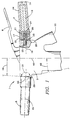
- Fig. 1 is a schematic, front elevational view, in partial cross section, with parts removed, of a paving breaker of the invention; and
- Fig. 2 is view similar to Fig. 1 wherein the handle is shown flexed into a downward position.
- Referring to the Fig. 1, there is shown the fluid-actuated
paving beaker 1, having ahousing 3 which includes any well-known combination of parts not shown: reciprocal piston, fluid passageways and apertures to operate the piston, fluid entry ports to supply percussive fluid, exhaust passageways to exhaust the percussive fluid, and chuck means for retaining a moil in the front end of thehousing 3. The details of the operational features are not shown, as they are not part of the invention, so long as the device is operational. - Connected to the top end of
housing 3 is a pair of oppositely positionedhandles lever 9 is associated with one of thehandles 7 and is pressed downwardly by the palm of an operator to actuate the device, as is well known. Aconventional air inlet 11 is also shown schematically. - A
vibration absorbing handle 7 includes anelongated handle housing 13 having a longitudinal axis ofsymmetry 15, afirst end 17, asecond end 19, and abore 21 coaxial withaxis 15. Bore 21 forms an opening 23 atfirst end 17 and extends intohandle housing 13. Asupport member 25 is connected to a portion oftool housing 3.Support member 25 is coaxial withaxis 15 and extends intobore 21. - A hollow, tubular,
elastic flex member 27 inbore 21, is coaxial withaxis 15. Flexmember 27 has affixed therein a hollow,tubular bushing 28, coaxial withaxis 15.Bushing 28 has a bore therethrough and is threaded on the surface forming the bore. Flexmember 27 and bushing 28 are telescoped oversupport member 25 and extend inbore 21. Flexmember 27 is permanently affixed to handlehousing 13 and threadably affixed to supportmember 25 via bushing 28. Flexmember 27 provides elasticity for flexibility, and bushing 28 provides strength for connection to supportmember 25. - Handle
housing 13contacts tool housing 3 at anangled surface 29 ontool housing 3.Angled surface 29 has anangle 31 with an outwardly extendingapex 33 positioned ataxis 15, whereby handlehousing 13 can rock back and forth overapex 33, whenflex member 27 is flexed. I preferangle 31 to be about 170 degrees. - As seen in Fig. 1,
angled surface 29 is formed, preferably, by two intersecting planes.Upper plane 35 is oriented to face toward a top end ofhousing 3, andlower plane 37 is oriented to face toward a lower end ofhousing 3, with both planes intersecting atapex 33. A gently curving surface be equivalent. -
Support member 25 is a pin threadably connected tohousing 3 coaxially alongaxis 15. Whenhandle 7 is not being pressed downwardly by an operator, it is in contact withupper plane 35 and notlower plane 37. As seen in Fig. 1,upper plane 35 forms anangle 36 with longitudinal axis ofsymmetry 40 oftool housing 3.Lower plane 37 forms anangle 42 withtool housing axis 40. I preferangle 36 to be about 2 degrees, andangle 42 to be about 8 degrees. - With upper and lower planes, 35, 37 positioned thusly,
upper plane 35 provides a "stop" against whichhandle 7 is positioned when the operator releases downward pressure, such as when the device is not being operated, or when the operator wishes to exert upward pressure, to release a stuck moil.Lower plane 37 provides a "stop" against whichhandle 7 is positioned when the operator applies sufficient downward force. Thus, it can be understood thathandle 7 is flexible in the downward, direction, but does not work against the drill operator's upward pulling force. Also, by reason of the universal flexibility offlex member 27, even when thehandle 7 is contacting the "stop" ofupper plane 35 or the "stop" oflower plane 37, the handle can be flexed in other directions than up or down, respectively, so it still can absorb some amount of vibrations. -
Housing 13 is completely encased in amonolithic coating 44 of suitable elastomeric material, such as rubber, to absorb vibrations. I prefer to providehandle 7 as a unified part in which theflex member 27 is permanently affixed inhousing 13, with bushing 28 permanently affixed toflex member 27, and the total combination molded incoating 44. I preferflex member 27 to be provided from neoprene material.
Claims (7)
- A vibration absorbing handle (7) for a power tool having an elongated handle housing (13) with a longitudinal axis of symmetry (15), wherein a bore (21) coaxial with said axis (15) forms an opening (23) extending into said handle housing (13); a support member (25) connected to a portion of said tool housing (3) and coaxial with said axis (15), extends into said bore (21); a hollow, tubular, elastic flex member (27) in said bore (21), coaxial with said axis (15), telescopes over said support member (25), and is affixed to said handle housing (13) and to said support member (25), characterized in that said handle housing (13) contacting said tool housing (3) at an angled surface (29) on said tool housing (3), said surface (29) having an angle (31) with an outwardly extending apex (33) positioned at said axis (15), whereby said handle (7) can rock back and forth over said apex (33), when said flex member (27) is flexed.
- The handle (7) of claim 1, in which said flex member (27) has affixed therein a hollow, tubular bushing (28), coaxial with said axis.
- The handle (7) of claim 2, in which said handle housing (13) is covered with an elastic, vibration absorbing coating (44).
- The handle (7) of claim 3, in which said flex member (27) is made from neoprene material.
- A percussion operated power tool having a pair of oppositely positioned, outwardly extending, vibration absorbing handles (5 and 7) affixed to the power tool via a tool housing (3); each vibration absorbing handle (7) having an elongated handle housing (13) with a longitudinal axis of symmetry (15), wherein a bore (21) coaxial with said axis (15) forms an opening (23) extending into said handle housing (13); a support member (25) connected to a portion of said tool housing (3) and coaxial with said axis (15), extends into said bore (21); a hollow, tubular, elastic flex member (27) in said bore (21), coaxial with said axis (15), telescopes over said support member (25), and is affixed to said handle housing (13) and to said support member (25), characterized in that said handle housing (13) contacting said tool housing (3) at an angled surface (29) on said tool housing (3), said surface (29) having an angle (31) with an outwardly extending apex (33) positioned at said axis (15), whereby said handle (7) can rock back and forth over said apex (33), when said flex member (27) is flexed.
- The tool of claim 5, wherein each handle housing (13) is covered with an elastic, vibration absorbing material (44).
- The tool of claim 6, in which said flex member (27) is made from neoprene material.
Applications Claiming Priority (3)
| Application Number | Priority Date | Filing Date | Title |
|---|---|---|---|
| US67779 | 1993-05-26 | ||
| US08/067,779 US5273120A (en) | 1993-05-26 | 1993-05-26 | Power tool with a vibration absorbing handle |
| PCT/US1993/010492 WO1994027789A1 (en) | 1993-05-26 | 1993-11-01 | Power tool with a vibration absorbing handle |
Publications (2)
| Publication Number | Publication Date |
|---|---|
| EP0700328A1 EP0700328A1 (en) | 1996-03-13 |
| EP0700328B1 true EP0700328B1 (en) | 1997-01-02 |
Family
ID=22078361
Family Applications (1)
| Application Number | Title | Priority Date | Filing Date |
|---|---|---|---|
| EP94900486A Expired - Lifetime EP0700328B1 (en) | 1993-05-26 | 1993-11-01 | Power tool with a vibration absorbing handle |
Country Status (9)
| Country | Link |
|---|---|
| US (1) | US5273120A (en) |
| EP (1) | EP0700328B1 (en) |
| JP (1) | JPH09500332A (en) |
| CN (1) | CN1097368A (en) |
| CA (1) | CA2160902A1 (en) |
| DE (1) | DE69307156T2 (en) |
| TW (1) | TW318423U (en) |
| WO (1) | WO1994027789A1 (en) |
| ZA (1) | ZA938368B (en) |
Cited By (1)
| Publication number | Priority date | Publication date | Assignee | Title |
|---|---|---|---|---|
| EP3213879A1 (en) | 2016-03-03 | 2017-09-06 | HILTI Aktiengesellschaft | Vibration reducing auxiliary handle |
Families Citing this family (38)
| Publication number | Priority date | Publication date | Assignee | Title |
|---|---|---|---|---|
| US5365637A (en) * | 1993-06-15 | 1994-11-22 | Ingersoll-Rand Company | Flex handle for a power tool |
| SE504957C2 (en) * | 1994-02-28 | 1997-06-02 | Berema Atlas Copco Ab | Machine skewer with handle fitted back piece |
| US5591070A (en) * | 1994-08-08 | 1997-01-07 | Indresco Inc. | Air tool with exhaust diverting valve |
| US5588903A (en) * | 1994-08-08 | 1996-12-31 | Indresco Inc. | Ergonomic power tool |
| US5732602A (en) * | 1996-03-12 | 1998-03-31 | Schwartz; Noah | Handle having resilient material incorporated therein |
| DE19730356C2 (en) * | 1997-07-15 | 2001-05-17 | Wacker Werke Kg | Vibration-damped breaker and / or hammer drill |
| DE29700003U1 (en) * | 1997-01-02 | 1997-02-27 | Wacker-Werke Gmbh & Co Kg, 85084 Reichertshofen | Breaking and / or hammer drill |
| DE19925281B4 (en) * | 1999-06-02 | 2014-10-02 | Andreas Stihl Ag & Co. | Hand-held implement, in particular hedge trimmer with vibration-damped handles |
| DE10005080C1 (en) * | 2000-02-04 | 2001-08-02 | Bosch Gmbh Robert | Hand tool has handle with handle part fixed to casing by elastic, vibration-damping element and fixing part fixed at elastic element |
| US6513406B1 (en) * | 2000-05-22 | 2003-02-04 | Freightliner Llc | Lever with vibration isolated knob |
| US6321417B1 (en) * | 2000-06-21 | 2001-11-27 | Genlyte Thomas Group Llc | Ergonomical tool handle |
| EP1166971A3 (en) * | 2000-06-27 | 2004-01-02 | Framatome Connectors International | Dampening system for tool handles |
| US6805207B2 (en) * | 2001-01-23 | 2004-10-19 | Black & Decker Inc. | Housing with functional overmold |
| CN1328016C (en) * | 2001-01-23 | 2007-07-25 | 布莱克-德克尔公司 | Power tools with functional overmolded housings |
| US20050061524A1 (en) * | 2001-01-23 | 2005-03-24 | Hagan Todd A. | Housing with functional overmold |
| DE10130548B4 (en) * | 2001-06-25 | 2008-01-03 | Robert Bosch Gmbh | Additional handle |
| CN2537524Y (en) * | 2002-04-30 | 2003-02-26 | 苏州宝时得电动工具有限公司 | Electric tool unit with at least one handle |
| GB2402098B (en) * | 2003-05-21 | 2007-10-17 | Black & Decker Inc | Vibration reduction apparatus for power tool and power tool incorporating such apparatus |
| DE10347944B4 (en) * | 2003-10-15 | 2016-11-10 | Robert Bosch Gmbh | Additional handle |
| US7039986B2 (en) | 2004-02-05 | 2006-05-09 | Multiquip, Inc. | Vibration isolation machine handle |
| US20060207063A1 (en) * | 2005-03-01 | 2006-09-21 | Multiquip. Inc. | Vibration dampening handle |
| DE102005046432A1 (en) * | 2005-09-28 | 2007-03-29 | Robert Bosch Gmbh | Electrical machine tool e.g. grinding device, has grip unit, swivelably formed about swivel axis at pivotal point, including vibration damping device, where axis is arranged parallel to longitudinal extension of grip frame of grip unit |
| US8756766B2 (en) * | 2005-10-25 | 2014-06-24 | Black & Decker Inc. | Vibration dampening handle for a powered apparatus |
| US7676890B2 (en) * | 2005-10-25 | 2010-03-16 | Black And Decker, Inc. | Vibration dampening handle for a powered apparatus |
| EP1867443B1 (en) * | 2006-06-14 | 2009-07-15 | AEG Electric Tools GmbH | Auxiliary handle for a manually operated machine tool |
| CA493745A (en) * | 2006-10-04 | 1953-06-16 | E. Glassburn William | Bridge-connected relay |
| DE102007012301A1 (en) * | 2006-10-25 | 2008-04-30 | Robert Bosch Gmbh | Handle e.g. auxiliary handle, for e.g. angle grinder, has damping unit provided with mounting unit between grip unit and support unit, where support unit forms rear section with mounting unit in grip unit |
| DE102007011787A1 (en) * | 2007-03-12 | 2008-09-18 | Robert Bosch Gmbh | Handle for use with e.g. boring machine, has gripping unit and fastening unit arranged at distance from each other by damping unit, where contact surfaces of gripping and fastening units are profiled such that surfaces are enlarged |
| DE102007012312A1 (en) * | 2007-03-14 | 2008-09-18 | Robert Bosch Gmbh | handle |
| DE102007000408A1 (en) * | 2007-07-27 | 2009-01-29 | Hilti Aktiengesellschaft | Hand tool |
| DE102008000414A1 (en) * | 2008-02-26 | 2009-08-27 | Robert Bosch Gmbh | Handle for electric hand tool |
| DE102009002463A1 (en) * | 2009-04-17 | 2010-10-21 | Hilti Aktiengesellschaft | Side handle |
| DE102011078376A1 (en) * | 2011-06-30 | 2013-01-03 | Robert Bosch Gmbh | Handle device, in particular for hand tools |
| US8966773B2 (en) | 2012-07-06 | 2015-03-03 | Techtronic Power Tools Technology Limited | Power tool including an anti-vibration handle |
| CN102960092A (en) * | 2012-12-17 | 2013-03-13 | 长铃集团有限公司 | Micro-cultivator and handle thereof |
| GB201518088D0 (en) * | 2015-10-13 | 2015-11-25 | Black & Decker Inc | Pavement Breaker |
| CN219311210U (en) | 2021-05-14 | 2023-07-07 | 创科无线普通合伙 | Handle for power tool |
| JP2023090449A (en) * | 2021-12-17 | 2023-06-29 | 株式会社マキタ | power tools |
Family Cites Families (20)
| Publication number | Priority date | Publication date | Assignee | Title |
|---|---|---|---|---|
| DE55630C (en) * | DREYER, ROSENKRANZ & DROOP in Hannover | Oil reservoir for crankpin conaxially connected to the crankshaft | ||
| US786050A (en) * | 1904-09-19 | 1905-03-28 | Clarence H Richwood | Fluid-actuated vibrator. |
| US2134863A (en) * | 1938-06-13 | 1938-11-01 | Myrtle C Dvorak | Crayon holder and protector |
| GB610525A (en) * | 1943-12-23 | 1948-10-18 | Pierre Cyrille Marie Daman | Handle for pneumatic hammers |
| US2830463A (en) * | 1950-05-22 | 1958-04-15 | Outboard Marine Corp | Wobble grip control |
| US2831463A (en) * | 1955-07-07 | 1958-04-22 | Atlas Copco Ab | Cushioning device for hammer tools |
| US2984210A (en) * | 1958-07-15 | 1961-05-16 | Thor Power Tool Co | Shock-absorbing handle structure for pneumatic tools |
| DE8006965U1 (en) * | 1980-03-14 | 1981-08-27 | Robert Bosch Gmbh, 7000 Stuttgart | ADDITIONAL HANDLE FOR A HAND MACHINE TOOL |
| SE438280B (en) * | 1983-04-22 | 1985-04-15 | Roland Andersson | VIBRATION DUMPING HANDLE |
| US4648468A (en) * | 1985-06-26 | 1987-03-10 | Honsa Technologies | Portable powered tool with vibration damping |
| DE3608700A1 (en) * | 1986-03-15 | 1987-09-17 | Bosch Gmbh Robert | HAND MACHINE TOOL WITH A RECORD FOR AN ADDITIONAL HANDLE |
| JPH0625288Y2 (en) * | 1987-03-18 | 1994-07-06 | 株式会社共立 | Anti-vibration mounting device for chain handle |
| JP2534318B2 (en) * | 1988-04-30 | 1996-09-11 | 日立工機株式会社 | Anti-vibration handle for power tools |
| US4949457A (en) * | 1988-08-03 | 1990-08-21 | Warner-Lambert Company | Soft resilient razor handle |
| SE467635B (en) * | 1988-09-30 | 1992-08-17 | Electrolux Ab | Vibration damper in motor saw |
| EP0391856A3 (en) * | 1989-04-07 | 1992-07-08 | SIG Schweizerische Industrie-Gesellschaft | Pneumatic hammer |
| DE4011124A1 (en) * | 1990-04-06 | 1991-10-10 | Metabowerke Kg | VIBRATION DAMPED HANDLE |
| DE9004091U1 (en) * | 1990-04-09 | 1990-06-21 | Metabowerke GmbH & Co, 7440 Nürtingen | Vibration-damped handle |
| US5054562A (en) * | 1990-05-02 | 1991-10-08 | Honsa Ergonomic Technologies, Inc. | Vibration-isolated power tool |
| SE467690B (en) * | 1990-12-11 | 1992-08-31 | Atlas Copco Tools Ab | VIBRATION INSULATED TOOL HANDLE |
-
1993
- 1993-05-26 US US08/067,779 patent/US5273120A/en not_active Expired - Fee Related
- 1993-10-29 TW TW085210927U patent/TW318423U/en unknown
- 1993-11-01 WO PCT/US1993/010492 patent/WO1994027789A1/en not_active Ceased
- 1993-11-01 EP EP94900486A patent/EP0700328B1/en not_active Expired - Lifetime
- 1993-11-01 JP JP7500586A patent/JPH09500332A/en active Pending
- 1993-11-01 CA CA002160902A patent/CA2160902A1/en not_active Abandoned
- 1993-11-01 DE DE69307156T patent/DE69307156T2/en not_active Expired - Fee Related
- 1993-11-09 ZA ZA938368A patent/ZA938368B/en unknown
-
1994
- 1994-05-14 CN CN94106042A patent/CN1097368A/en active Pending
Cited By (1)
| Publication number | Priority date | Publication date | Assignee | Title |
|---|---|---|---|---|
| EP3213879A1 (en) | 2016-03-03 | 2017-09-06 | HILTI Aktiengesellschaft | Vibration reducing auxiliary handle |
Also Published As
| Publication number | Publication date |
|---|---|
| CA2160902A1 (en) | 1994-12-08 |
| EP0700328A1 (en) | 1996-03-13 |
| CN1097368A (en) | 1995-01-18 |
| TW318423U (en) | 1997-10-21 |
| JPH09500332A (en) | 1997-01-14 |
| DE69307156D1 (en) | 1997-02-13 |
| WO1994027789A1 (en) | 1994-12-08 |
| ZA938368B (en) | 1994-09-16 |
| DE69307156T2 (en) | 1997-06-12 |
| US5273120A (en) | 1993-12-28 |
Similar Documents
| Publication | Publication Date | Title |
|---|---|---|
| US5273120A (en) | Power tool with a vibration absorbing handle | |
| US4576241A (en) | Tool assembly and handle assembly therefor | |
| RU2671225C2 (en) | Auxiliary handle and reciprocating power tool having same | |
| US6863479B2 (en) | Supplemental handle | |
| JP2001510099A (en) | Percussion hammer and / or drill hammer having vibration damping action | |
| CN1762667B (en) | Hand-held power tools with vibration-damped pistol grips | |
| EP2647474B1 (en) | Portable power tool | |
| US7721390B2 (en) | Handle for hand-held power tool | |
| US20040154813A1 (en) | Vibration-decoupling arrangement for supporting a percussion unit in a hand-held percussion power tool | |
| CA2013198A1 (en) | Paving breakers and supports therefor | |
| CN101247926A (en) | electric machine tool | |
| CA2172090A1 (en) | Device for transmitting impulse-like blows to a continuously rotatable tool bit | |
| CS8901941A2 (en) | Vibroinsulating connection of hand-operated pneumatic tools' constructional assemblies | |
| JPH04504152A (en) | impact bucket device | |
| CN101400485A (en) | Machine tool and method for the operation thereof | |
| CN101224572B (en) | Hand machine tool with vibration isolating handle in region of swivel joint | |
| US3275089A (en) | Handle means for percussive tool | |
| US20050042051A1 (en) | Handle for a hand-held power tool | |
| US20020054796A1 (en) | Electric hand tool implement | |
| JP4125812B2 (en) | Hand-held machine tool | |
| US4586230A (en) | Portable pulling apparatus | |
| US4458416A (en) | Vibration damped portable impact tool | |
| US2589075A (en) | Toolholder for impact tools | |
| EP0294351B1 (en) | Vibration dampened machine handle | |
| US2882927A (en) | Handle for pneumatic tools |
Legal Events
| Date | Code | Title | Description |
|---|---|---|---|
| PUAI | Public reference made under article 153(3) epc to a published international application that has entered the european phase |
Free format text: ORIGINAL CODE: 0009012 |
|
| 17P | Request for examination filed |
Effective date: 19951127 |
|
| AK | Designated contracting states |
Kind code of ref document: A1 Designated state(s): DE GB IT SE |
|
| GRAG | Despatch of communication of intention to grant |
Free format text: ORIGINAL CODE: EPIDOS AGRA |
|
| 17Q | First examination report despatched |
Effective date: 19960412 |
|
| GRAH | Despatch of communication of intention to grant a patent |
Free format text: ORIGINAL CODE: EPIDOS IGRA |
|
| GRAH | Despatch of communication of intention to grant a patent |
Free format text: ORIGINAL CODE: EPIDOS IGRA |
|
| GRAA | (expected) grant |
Free format text: ORIGINAL CODE: 0009210 |
|
| AK | Designated contracting states |
Kind code of ref document: B1 Designated state(s): DE GB IT SE |
|
| ITF | It: translation for a ep patent filed | ||
| REF | Corresponds to: |
Ref document number: 69307156 Country of ref document: DE Date of ref document: 19970213 |
|
| PG25 | Lapsed in a contracting state [announced via postgrant information from national office to epo] |
Ref country code: GB Free format text: LAPSE BECAUSE OF NON-PAYMENT OF DUE FEES Effective date: 19971101 |
|
| PG25 | Lapsed in a contracting state [announced via postgrant information from national office to epo] |
Ref country code: SE Free format text: LAPSE BECAUSE OF NON-PAYMENT OF DUE FEES Effective date: 19971102 |
|
| PLBE | No opposition filed within time limit |
Free format text: ORIGINAL CODE: 0009261 |
|
| STAA | Information on the status of an ep patent application or granted ep patent |
Free format text: STATUS: NO OPPOSITION FILED WITHIN TIME LIMIT |
|
| 26N | No opposition filed | ||
| GBPC | Gb: european patent ceased through non-payment of renewal fee |
Effective date: 19971101 |
|
| PG25 | Lapsed in a contracting state [announced via postgrant information from national office to epo] |
Ref country code: DE Free format text: LAPSE BECAUSE OF NON-PAYMENT OF DUE FEES Effective date: 19980801 |
|
| EUG | Se: european patent has lapsed |
Ref document number: 94900486.5 |
|
| PG25 | Lapsed in a contracting state [announced via postgrant information from national office to epo] |
Ref country code: IT Free format text: LAPSE BECAUSE OF NON-PAYMENT OF DUE FEES Effective date: 20051101 |