EP0700234B1 - Device for supporting a composite self-baking electrode for an electric arc furnace - Google Patents
Device for supporting a composite self-baking electrode for an electric arc furnace Download PDFInfo
- Publication number
- EP0700234B1 EP0700234B1 EP95420249A EP95420249A EP0700234B1 EP 0700234 B1 EP0700234 B1 EP 0700234B1 EP 95420249 A EP95420249 A EP 95420249A EP 95420249 A EP95420249 A EP 95420249A EP 0700234 B1 EP0700234 B1 EP 0700234B1
- Authority
- EP
- European Patent Office
- Prior art keywords
- column
- electrode
- ferrule
- support
- electric arc
- Prior art date
- Legal status (The legal status is an assumption and is not a legal conclusion. Google has not performed a legal analysis and makes no representation as to the accuracy of the status listed.)
- Expired - Lifetime
Links
Images
Classifications
-
- H—ELECTRICITY
- H05—ELECTRIC TECHNIQUES NOT OTHERWISE PROVIDED FOR
- H05B—ELECTRIC HEATING; ELECTRIC LIGHT SOURCES NOT OTHERWISE PROVIDED FOR; CIRCUIT ARRANGEMENTS FOR ELECTRIC LIGHT SOURCES, IN GENERAL
- H05B7/00—Heating by electric discharge
- H05B7/02—Details
- H05B7/10—Mountings, supports, terminals or arrangements for feeding or guiding electrodes
- H05B7/107—Mountings, supports, terminals or arrangements for feeding or guiding electrodes specially adapted for self-baking electrodes
-
- H—ELECTRICITY
- H05—ELECTRIC TECHNIQUES NOT OTHERWISE PROVIDED FOR
- H05B—ELECTRIC HEATING; ELECTRIC LIGHT SOURCES NOT OTHERWISE PROVIDED FOR; CIRCUIT ARRANGEMENTS FOR ELECTRIC LIGHT SOURCES, IN GENERAL
- H05B7/00—Heating by electric discharge
- H05B7/02—Details
- H05B7/06—Electrodes
- H05B7/08—Electrodes non-consumable
- H05B7/085—Electrodes non-consumable mainly consisting of carbon
- H05B7/09—Self-baking electrodes, e.g. Söderberg type electrodes
Definitions
- the invention relates to the field of oven electrodes electric arc and, more specifically, electrodes self-cooking, called SODERBERG electrodes, for carbothermal reduction, such as production furnaces metallurgical silicon.
- this support piece is a column forming a pre-baked carbon or graphite electrode, consisting elements assembled by means of nipples, i.e. double conical thread fittings, made in the same material, and screwed onto the two elements to be assembled.
- the positioning of the collets of the column does not allow large amplitude displacements. he must therefore frequently reposition the clamps on the column as the electrode is consumed, which contributes to worsening the damage caused to the spine by pliers.
- the subject of the invention is a device for mounting a self-cooking electrode, fitted with a metal ferrule cylindrical and a central column in graphite or precooked carbon consisting of elements assembled by nipples, not having the disadvantages mentioned above.
- the central column is suspended from a support which is movable vertically with respect to the ferrule over a length greater than that of the elements.
- the displacement of the support can be obtained using jacks.
- the column can be fixed to the mobile support using a piece threaded, integral with the support and the thread of which is identical to that of the assembly nipples of the elements of the column.
- the composite electrode (1) consists of a ferrule cylindrical metal (2) used to contain the carbonaceous paste introduced at its top and which will gradually cook in going down into the oven.
- a central column (3) cylindrical of the same axis as the ferrule, is made up of elements identical in pre-baked carbon or graphite, provided at their two ends of tapered and threaded conical holes above the others by nipples (4).
- Column (3) is retained at its top by a metal part (5) reproducing at its end the thread of the nipples (4).
- the part (5) is directly screwed onto the upper element of the column (3).
- This part (5) is supported by a frame (6), the relative position with respect to the shell (2) and the frame (7) of which it is integral, is controlled by two jacks (8) whose stroke is greater than the length of the elements forming the column (3).
- This assembly allows the electrode (1) to be slid a length equal to or greater than that of an element in column (3) without having to resume fixing between the column (3) and the piece (5).
- the stroke of the cylinders (8) is sufficient to allow the length of the column to be extended by one element (3) by having to make only one takeover operation on column (3). So the surface of the carbon elements or graphite is not damaged by any kind of tightening and the tensile strength of the column (3) is fully preserved.
- the upper element of the column (3) is fixed to a part (5) steel finished with a shape identical to that of a nipple (4).
- Mobile equipment consisting of a chassis (6) supporting the part (5) and jacks (8) allows to support and position the electrode over a length of 1850 mm in acting only on the volume of oil injected into the cylinders.
Description
L'invention concerne le domaine des électrodes pour four électrique à arc et, plus spécialement, des électrodes à autocuisson, dites électrodes SODERBERG, pour fours de réduction carbothermique, tels que les fours de production de silicium métallurgique.The invention relates to the field of oven electrodes electric arc and, more specifically, electrodes self-cooking, called SODERBERG electrodes, for carbothermal reduction, such as production furnaces metallurgical silicon.
Le principe des électrodes à autocuisson, qui consiste à introduire une pâte carbonée crue dans le four à l'intérieur d'une virole cylindrique et à cuire cette pâte de manière continue au cours de son utilisation dans le four, est connu depuis le brevet déposé en 1917 par C.W. SODERBERG, G. SEM et J. WESTLY au nom de la société Det Norske Aktielselkap for Elektrokemisk Industri (correspondant à FR 488778).The principle of self-cooking electrodes, which consists of put a raw carbon paste in the oven inside a cylindrical shell and bake this dough so continues during use in the oven, is known since the patent filed in 1917 by C.W. SODERBERG, G. SEM and J. WESTLY on behalf of the company Det Norske Aktielselkap for Elektrokemisk Industri (corresponding to FR 488778).
Cette technique aujourd'hui largement utilisée conduit à constituer des électrodes continues qui contiennent, si on ne fait rien pour le prévenir, environ 2,5% de fer provenant de la virole en acier.This widely used technique today leads to constitute continuous electrodes which contain, if one does not does nothing to prevent it, about 2.5% iron from the steel ferrule.
Pour constituer des électrodes continues à plus faible teneur en fer, plusieurs solutions ont été proposées, qui consistent toutes à désolidariser mécaniquement l'électrode et sa virole, de façon à pouvoir glisser l'électrode sans allonger d'autant la virole. On utilise alors, au lieu de la virole munie d'ailettes internes pour le soutien de l'électrode prévue dans le dispositif initial, une virole lisse sans ailettes. Cette disposition a d'ailleurs été testée par ELEKTROKEMISK dès 1917 (cf. Sôderberg Electrode 75 Year Anniversary Seminar, Kristiansand, 6-8 Juin 1994, G. SEM "The conception and birth of the Söderberg Electrode.") To build lower content continuous electrodes in iron, several solutions have been proposed, which consist all to mechanically separate the electrode and its ferrule, so as to be able to slide the electrode without lengthening as much the ferrule. We then use, instead of the ferrule provided internal fins to support the electrode provided in the initial device, a smooth shell without fins. This provision has also been tested by ELEKTROKEMISK from 1917 (cf. Sôderberg Electrode 75 Year Anniversary Seminar, Kristiansand, 6-8 June 1994, G. SEM "The conception and birth of the Söderberg Electrode. ")
La suppression des ailettes ne permettant plus de supporter le poids de l'électrode par l'intermédiaire de sa virole, il faut alors avoir recours à un montage différent du montage Söderberg classique et consistant à supporter le poids de l'électrode au moyen d'une pièce prisonnière de la pâte cuite, qui se consomme en même temps que l'électrode elle-même.The removal of the fins no longer making it possible to support the weight of the electrode via its ferrule, it is necessary then use a different mounting from the mounting Söderberg classic and consisting of supporting the weight of the electrode by means of a captive piece of the cooked dough, which is consumed at the same time as the electrode itself.
Dans le brevet italien 606568 déposé en 1959 par la société EDISON, cette pièce est une bande d'acier perforée.In Italian patent 606568 filed in 1959 by the company EDISON, this piece is a perforated steel strip.
Dans le brevet US 4575856 de J.A. PERSSON délivré le 11/03/1986, cette pièce de support est une colonne formant une électrode précuite en carbone ou en graphite, constituée d'éléments assemblés au moyen de nipples, c'est à dire de raccords à double filetage cônique, réalisés dans le même matériau, et vissés sur les deux éléments à assembler. Le brevet FR 2683421 déposé par la société espagnole CARBUROS METALLICOS, revendique diverses adaptations de cette technique.In US Patent 4,575,856 to J.A. PERSSON issued on 03/11/1986, this support piece is a column forming a pre-baked carbon or graphite electrode, consisting elements assembled by means of nipples, i.e. double conical thread fittings, made in the same material, and screwed onto the two elements to be assembled. The patent FR 2683421 filed by the Spanish company CARBUROS METALLICOS, claims various adaptations of this technical.
Le montage proposé dans ces deux derniers brevets présente un certain nombre d'inconvénients.The assembly proposed in these last two patents presents a a number of drawbacks.
D'une part, l'effort mécanique nécessaire pour compenser le poids de l'électrode est transmis à la colonne par un système de pinces. Cet effort peut atteindre des valeurs importantes, de l'ordre de 50000 à 75000 N. Il faut donc exercer sur la pince une pression de serrage très importante, car le coefficient de frottement entre le carbone et l'acier est faible. En exploitation, ce type de montage entraíne une dégradation de la surface de la colonne de graphite qui augmente les risques de rupture du fait de l'effort de traction auquel elle est soumise. Or, cette rupture peut avoir des conséquences graves sur l'électrode elle-même ainsi que sur le four où elle est montée.On the one hand, the mechanical effort necessary to compensate for the weight of the electrode is transmitted to the column by a system pliers. This effort can reach important values, of the order of 50,000 to 75,000 N. It is therefore necessary to exercise on the pinches a very high clamping pressure, because the coefficient of friction between carbon and steel is low. In operation, this type of mounting results in a degradation of the surface of the graphite column which increases the risk of rupture due to the effort of traction to which it is subjected. However, this rupture may have serious consequences on the electrode itself as well as on the oven where it is mounted.
D'autre part, le positionnement des pinces de serrage de la colonne ne permet pas des déplacements de grande amplitude. Il faut donc repositionner fréquemment les pinces sur la colonne au fur et à mesure que se consomme l'électrode, ce qui contribue à aggraver les dommages causés à la colonne par les pinces. On the other hand, the positioning of the collets of the column does not allow large amplitude displacements. he must therefore frequently reposition the clamps on the column as the electrode is consumed, which contributes to worsening the damage caused to the spine by pliers.
L'invention a pour objet un dipositif de montage d'une électrode à autocuisson, munie d'une virole métallique cylindrique et d'une colonne centrale en graphite ou en carbone précuit constituée d'éléments assemblés par des nipples, ne présentant pas les inconvénients mentionnés ci-dessus.The subject of the invention is a device for mounting a self-cooking electrode, fitted with a metal ferrule cylindrical and a central column in graphite or precooked carbon consisting of elements assembled by nipples, not having the disadvantages mentioned above.
Selon l'invention, la colonne centrale est suspendue à un support qui est mobile dans le sens vertical par rapport à la virole sur une longueur supérieure à celle des éléments. Le déplacement du support peut être obtenu à l'aide de vérins. La colonne peut être fixée au support mobile à l'aide d'une pièce filetée, solidaire du support et dont le filetage est identique à celui des nipples d'assemblage des éléments de la colonne.According to the invention, the central column is suspended from a support which is movable vertically with respect to the ferrule over a length greater than that of the elements. The displacement of the support can be obtained using jacks. The column can be fixed to the mobile support using a piece threaded, integral with the support and the thread of which is identical to that of the assembly nipples of the elements of the column.
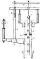
Un mode de réalisation particulier de l'invention sera décrit à l'aide de la figure unique représentant une vue en coupe axiale de l'électrode composite et de son dispositif de montage.L'électrode composite (1) est constituée d'une virole cylindrique métallique (2) servant à contenir la pâte carbonée introduite à son sommet et qui va cuire progressivement en descendant dans le four. Une colonne centrale (3), cylindrique de même axe que la virole, est constituée d'éléments identiques en carbone précuit ou en graphite, munis à leurs deux extrêmités de trous côniques filetés et assemblés les uns au-dessus des autres par des nipples (4). La colonne (3) est retenue à son sommet par une pièce métallique (5) reproduisant à son extrêmité le filetage des nipples (4) . La pièce (5) est directement vissée sur l'élément supérieur de la colonne (3).A particular embodiment of the invention will be described using the single figure representing a sectional view axial view of the composite electrode and its device The composite electrode (1) consists of a ferrule cylindrical metal (2) used to contain the carbonaceous paste introduced at its top and which will gradually cook in going down into the oven. A central column (3), cylindrical of the same axis as the ferrule, is made up of elements identical in pre-baked carbon or graphite, provided at their two ends of tapered and threaded conical holes above the others by nipples (4). Column (3) is retained at its top by a metal part (5) reproducing at its end the thread of the nipples (4). The part (5) is directly screwed onto the upper element of the column (3).
Cette pièce (5) est supportée par un châssis (6) dont la position relative par rapport à la virole (2) et au bâti (7) dont elle est solidaire, est commandée par deux vérins (8) dont la course est supérieure à la longueur des éléments formant la colonne (3).This part (5) is supported by a frame (6), the relative position with respect to the shell (2) and the frame (7) of which it is integral, is controlled by two jacks (8) whose stroke is greater than the length of the elements forming the column (3).
Ce montage permet de glisser l'électrode (1) d'une longueur égale ou supérieure à celle d'un élément de la colonne (3) sans avoir à reprendre la fixation entre la colonne (3) et la pièce (5). La course des vérins (8) est suffisante pour permettre d'allonger d'un élément la longueur de la colonne (3) en n'ayant à faire qu'une seule opération de reprise sur la colonne (3). Ainsi, la surface des éléments en carbone ou graphite n'est pas endommagée par un quelconque système de serrage et la résistance à la traction de la colonne (3) est intégralement conservée.This assembly allows the electrode (1) to be slid a length equal to or greater than that of an element in column (3) without having to resume fixing between the column (3) and the piece (5). The stroke of the cylinders (8) is sufficient to allow the length of the column to be extended by one element (3) by having to make only one takeover operation on column (3). So the surface of the carbon elements or graphite is not damaged by any kind of tightening and the tensile strength of the column (3) is fully preserved.
Sur un four de production de silicium métallurgique de 20 MW, équipé à l'origine d'électrodes précuites de diamètre 1250 mm, on a monté, à titre d'essai sur l'une des électrodes un dispositif de montage selon l'invention. La colonne (3) est constituée d'éléments de longueur unitaire 1700 mm et de diamètre 450 mm assemblés par des nipples (4).On a 20 MW metallurgical silicon production furnace, originally equipped with pre-baked electrodes with a diameter of 1250 mm, a test electrode was mounted on one of the electrodes mounting device according to the invention. Column (3) is consisting of elements of unit length 1700 mm and diameter 450 mm assembled by nipples (4).
L'élément supérieur de la colonne (3) est fixé à une pièce (5) en acier terminée par une forme identique à celle d'un nipple (4). Un équipement mobile constitué d'un châssis (6) supportant la pièce (5) et de vérins (8) permet de supporter et de positionner l'électrode sur une longueur de 1850 mm en agissant uniquement sur le volume d'huile injecté dans les vérins.The upper element of the column (3) is fixed to a part (5) steel finished with a shape identical to that of a nipple (4). Mobile equipment consisting of a chassis (6) supporting the part (5) and jacks (8) allows to support and position the electrode over a length of 1850 mm in acting only on the volume of oil injected into the cylinders.
Ce montage a permis de constater que la surface des éléments constituant la colonne (3) était restée intacte et que l'exploitation se faisait sans difficulté, malgré un effort de traction de 75000 N s'exerçant sur la colonne (3), effort mesuré au moyen de la pression d'huile sur les vérins (8).This assembly made it possible to note that the surface of the elements constituting column (3) had remained intact and that the exploitation was done without difficulty, despite an effort of 75,000 N traction exerted on the column (3), effort measured by means of oil pressure on the cylinders (8).
Claims (3)
- A device for mounting a self-baking composite electrode (1) for an electric arc furnace, which includes a metallic ferrule (2), a central column (3) of graphite or pre-baked carbon constituted by elements fitted together by means of nipples (4) and a carbonaceous paste between the ferrule (2) and the column (3), characterized in that the column (3) is suspended from a support (6) which is movable in the vertical direction with respect to the ferrule (2) along a length which is greater than the length of each of the elements.
- The device according to claim 1, characterized in that the relative movement of the support (6) with respect to the column (3) is obtained by means of screw jacks (8).
- The device according to either of claims 1 or 2, characterized in that the column (3) is fastened to the support (6) by means of a threaded piece (5) whose threading is identical to that of the nipples (4).
Applications Claiming Priority (2)
| Application Number | Priority Date | Filing Date | Title |
|---|---|---|---|
| FR9410774 | 1994-09-05 | ||
| FR9410774A FR2724219B1 (en) | 1994-09-05 | 1994-09-05 | DEVICE FOR MOUNTING A SELF-COOKING COMPOSITE ELECTRODE FOR ELECTRIC ARC OVEN |
Publications (2)
| Publication Number | Publication Date |
|---|---|
| EP0700234A1 EP0700234A1 (en) | 1996-03-06 |
| EP0700234B1 true EP0700234B1 (en) | 1999-10-13 |
Family
ID=9466795
Family Applications (1)
| Application Number | Title | Priority Date | Filing Date |
|---|---|---|---|
| EP95420249A Expired - Lifetime EP0700234B1 (en) | 1994-09-05 | 1995-09-04 | Device for supporting a composite self-baking electrode for an electric arc furnace |
Country Status (5)
| Country | Link |
|---|---|
| US (1) | US5577065A (en) |
| EP (1) | EP0700234B1 (en) |
| DE (1) | DE69512732T2 (en) |
| ES (1) | ES2139165T3 (en) |
| FR (1) | FR2724219B1 (en) |
Families Citing this family (7)
| Publication number | Priority date | Publication date | Assignee | Title |
|---|---|---|---|---|
| PL189321B1 (en) * | 1997-05-02 | 2005-07-29 | Silicium Becancour Inc | Soderberg-type electrode for obtaining siliceous alloys and metals |
| CA2204425A1 (en) * | 1997-05-02 | 1998-11-02 | Skw Canada Inc. | Electrode for silicon alloys and silicon metal |
| FR2770079B1 (en) * | 1997-10-22 | 2000-01-28 | Action Finances Ind | COMPOSITE ELECTRODE OF METALLURGY OVEN |
| BR9900252A (en) | 1999-02-02 | 2000-08-29 | Companhia Brasileira Carbureto | Stainless steel container for forming self-baking electrodes for use in electric reduction blast furnaces |
| BR9900253A (en) | 1999-02-02 | 2000-08-29 | Companhia Brasileira Carbureto | Aluminum and stainless steel container forming self-cooking electrodes for use in electric reduction furnaces |
| FR2797739B1 (en) | 1999-08-19 | 2001-09-21 | Invensil | SELF-COOKING COMPOSITE ELECTRODE MOUNTING DEVICE FOR ELECTRIC ARC OVEN |
| WO2019233549A1 (en) * | 2018-06-04 | 2019-12-12 | Rheinfelden Carbon Gmbh & Co. Kg | Self-baking electrode |
Family Cites Families (12)
| Publication number | Priority date | Publication date | Assignee | Title |
|---|---|---|---|---|
| IT606568A (en) * | ||||
| FR488778A (en) * | 1917-02-05 | 1918-11-14 | Det Norske Aktieselskab For Elektrokemisk Industri | Charcoal electrode firing process |
| US1579824A (en) * | 1924-07-12 | 1926-04-06 | Laurell Axel Hugo | Electrode consisting of lengths that can be joined together in a continuous manner |
| US3524004A (en) * | 1968-12-03 | 1970-08-11 | Ohio Ferro Alloys Corp | Non-metal reinforced self-baking electrode for electric furnaces |
| US3819841A (en) * | 1973-08-06 | 1974-06-25 | Pennsylvania Engineering Corp | Iron-free self-braking electrode |
| US4349910A (en) * | 1979-09-28 | 1982-09-14 | Union Carbide Corporation | Method and apparatus for orientation of electrode joint threads |
| DE3324692A1 (en) * | 1983-07-08 | 1985-01-17 | Sigri Elektrographit Gmbh, 8901 Meitingen | CONNECTION BETWEEN SECTIONS OF A CARBON OR GRAPHITE ELECTRODE |
| US4575856A (en) * | 1984-05-18 | 1986-03-11 | Pennsylvania Engineering Corporation | Iron free self baking electrode |
| US4736384A (en) * | 1985-12-23 | 1988-04-05 | Kyoei Steel Ltd. | Electrode adding apparatus |
| US4725161A (en) * | 1986-09-05 | 1988-02-16 | Union Carbide Corporation | Electrode joint |
| DE4010353A1 (en) * | 1990-03-28 | 1991-10-02 | Mannesmann Ag | Operating metallurgical furnace with self-baking electrode - lockable traction rod within electrode |
| ES2046098B1 (en) * | 1991-10-30 | 1994-08-01 | Espa Ola De Carburos Metalicos | IMPROVEMENTS ON THE CONTINUOUS MANUFACTURING PROCESS OF ELECTRODES FREE OF IMPURITIES AND IRON FOR ELECTRIC ARC FURNACES. |
-
1994
- 1994-09-05 FR FR9410774A patent/FR2724219B1/en not_active Expired - Lifetime
-
1995
- 1995-08-14 US US08/514,735 patent/US5577065A/en not_active Expired - Lifetime
- 1995-09-04 ES ES95420249T patent/ES2139165T3/en not_active Expired - Lifetime
- 1995-09-04 DE DE69512732T patent/DE69512732T2/en not_active Expired - Lifetime
- 1995-09-04 EP EP95420249A patent/EP0700234B1/en not_active Expired - Lifetime
Also Published As
| Publication number | Publication date |
|---|---|
| DE69512732T2 (en) | 2000-03-02 |
| US5577065A (en) | 1996-11-19 |
| EP0700234A1 (en) | 1996-03-06 |
| FR2724219B1 (en) | 1996-10-25 |
| DE69512732D1 (en) | 1999-11-18 |
| FR2724219A1 (en) | 1996-03-08 |
| ES2139165T3 (en) | 2000-02-01 |
Similar Documents
| Publication | Publication Date | Title |
|---|---|---|
| EP0700234B1 (en) | Device for supporting a composite self-baking electrode for an electric arc furnace | |
| FR2464839A1 (en) | HOLLOW STABILIZER FOR VEHICLES | |
| CA2165392C (en) | Mounting device for the self-baking commutation electrode of an electronic arc furnace | |
| CN209562041U (en) | A kind of fixed device of signal cable arrangement | |
| EP2665069B1 (en) | High voltage electrical transmission cable | |
| AU702610B2 (en) | Device for mounting a self-baking composite electrode for an electric arc furnace | |
| AU683182B2 (en) | Self-baking carbon electrode | |
| FR2519588A1 (en) | MACPHERSON-TYPE SUSPENSION LEG FOR DRIVEN STEERING WHEEL OF MOTOR VEHICLES | |
| CN2333479Y (en) | Square frame chain pipeline welding clamp | |
| EP1077588B1 (en) | Self-baking composite electrode assembly for electric arc furnace | |
| DE60033408D1 (en) | ELECTRIC LADDER WITH BUILT-IN OPTICAL FIBERS | |
| CN106567909B (en) | Guy clamp easy to use | |
| CN219937782U (en) | Device for quickly replacing insulator | |
| CN109217170A (en) | The replacement tool of ground electrode circuit insulator and fitting | |
| CN217026483U (en) | Steel wire rope with protection structure | |
| CN115411684A (en) | Overhead transmission line suspension clamp | |
| CN218371430U (en) | Aluminum alloy double-rocker inner suspension rotary holding pole | |
| CN107756277A (en) | Clamping means applied to building pipe | |
| CN112821332A (en) | Pre-twisted conductor spacer | |
| CN213705672U (en) | Novel bicycle frame | |
| JPH07336853A (en) | Twist preventing damper | |
| CN208902134U (en) | Device against shake is used in a kind of detection of flat type copper wire | |
| CN209830564U (en) | Argon arc welds defect preventing device | |
| CN208790897U (en) | A kind of bracket for steel strand wires installation | |
| JP4676446B2 (en) | Earth side arc horn device |
Legal Events
| Date | Code | Title | Description |
|---|---|---|---|
| PUAI | Public reference made under article 153(3) epc to a published international application that has entered the european phase |
Free format text: ORIGINAL CODE: 0009012 |
|
| AK | Designated contracting states |
Kind code of ref document: A1 Designated state(s): DE ES GB |
|
| 17P | Request for examination filed |
Effective date: 19960422 |
|
| GRAG | Despatch of communication of intention to grant |
Free format text: ORIGINAL CODE: EPIDOS AGRA |
|
| GRAG | Despatch of communication of intention to grant |
Free format text: ORIGINAL CODE: EPIDOS AGRA |
|
| GRAH | Despatch of communication of intention to grant a patent |
Free format text: ORIGINAL CODE: EPIDOS IGRA |
|
| 17Q | First examination report despatched |
Effective date: 19990209 |
|
| GRAH | Despatch of communication of intention to grant a patent |
Free format text: ORIGINAL CODE: EPIDOS IGRA |
|
| GRAA | (expected) grant |
Free format text: ORIGINAL CODE: 0009210 |
|
| AK | Designated contracting states |
Kind code of ref document: B1 Designated state(s): DE ES GB |
|
| REF | Corresponds to: |
Ref document number: 69512732 Country of ref document: DE Date of ref document: 19991118 |
|
| GBT | Gb: translation of ep patent filed (gb section 77(6)(a)/1977) |
Effective date: 19991202 |
|
| REG | Reference to a national code |
Ref country code: ES Ref legal event code: FG2A Ref document number: 2139165 Country of ref document: ES Kind code of ref document: T3 |
|
| PLBE | No opposition filed within time limit |
Free format text: ORIGINAL CODE: 0009261 |
|
| STAA | Information on the status of an ep patent application or granted ep patent |
Free format text: STATUS: NO OPPOSITION FILED WITHIN TIME LIMIT |
|
| 26N | No opposition filed | ||
| REG | Reference to a national code |
Ref country code: GB Ref legal event code: IF02 |
|
| REG | Reference to a national code |
Ref country code: DE Ref legal event code: R082 Ref document number: 69512732 Country of ref document: DE Representative=s name: WITTE, WELLER & PARTNER, DE |
|
| REG | Reference to a national code |
Ref country code: DE Ref legal event code: R082 Ref document number: 69512732 Country of ref document: DE Representative=s name: WITTE, WELLER & PARTNER PATENTANWAELTE MBB, DE Effective date: 20111118 Ref country code: DE Ref legal event code: R081 Ref document number: 69512732 Country of ref document: DE Owner name: FERROPEM, FR Free format text: FORMER OWNER: PECHINEY ELECTROMETALLURGIE, COURBEVOIE, FR Effective date: 20111118 |
|
| REG | Reference to a national code |
Ref country code: ES Ref legal event code: PC2A Owner name: FERROPEM Effective date: 20120808 |
|
| PGFP | Annual fee paid to national office [announced via postgrant information from national office to epo] |
Ref country code: DE Payment date: 20140728 Year of fee payment: 20 |
|
| PGFP | Annual fee paid to national office [announced via postgrant information from national office to epo] |
Ref country code: GB Payment date: 20140724 Year of fee payment: 20 Ref country code: ES Payment date: 20140919 Year of fee payment: 20 |
|
| REG | Reference to a national code |
Ref country code: DE Ref legal event code: R071 Ref document number: 69512732 Country of ref document: DE |
|
| REG | Reference to a national code |
Ref country code: GB Ref legal event code: PE20 Expiry date: 20150903 |
|
| PG25 | Lapsed in a contracting state [announced via postgrant information from national office to epo] |
Ref country code: GB Free format text: LAPSE BECAUSE OF EXPIRATION OF PROTECTION Effective date: 20150903 |
|
| REG | Reference to a national code |
Ref country code: ES Ref legal event code: FD2A Effective date: 20151229 |
|
| PG25 | Lapsed in a contracting state [announced via postgrant information from national office to epo] |
Ref country code: ES Free format text: LAPSE BECAUSE OF EXPIRATION OF PROTECTION Effective date: 20150905 |