EP0699911B1 - Tachymètre perfectionné et son application notamment aux machines tournantes de centrales électriques - Google Patents
Tachymètre perfectionné et son application notamment aux machines tournantes de centrales électriques Download PDFInfo
- Publication number
- EP0699911B1 EP0699911B1 EP95401987A EP95401987A EP0699911B1 EP 0699911 B1 EP0699911 B1 EP 0699911B1 EP 95401987 A EP95401987 A EP 95401987A EP 95401987 A EP95401987 A EP 95401987A EP 0699911 B1 EP0699911 B1 EP 0699911B1
- Authority
- EP
- European Patent Office
- Prior art keywords
- transmitter
- sensor
- pulse
- tachometer
- speed
- Prior art date
- Legal status (The legal status is an assumption and is not a legal conclusion. Google has not performed a legal analysis and makes no representation as to the accuracy of the status listed.)
- Expired - Lifetime
Links
- 230000003287 optical effect Effects 0.000 claims abstract description 17
- 239000000835 fiber Substances 0.000 claims description 11
- 238000007493 shaping process Methods 0.000 claims description 8
- 230000001939 inductive effect Effects 0.000 claims description 4
- 238000005259 measurement Methods 0.000 claims description 3
- 230000001131 transforming effect Effects 0.000 claims 1
- 229910052751 metal Inorganic materials 0.000 abstract description 4
- 239000013307 optical fiber Substances 0.000 abstract description 2
- 230000010355 oscillation Effects 0.000 abstract description 2
- 210000000056 organ Anatomy 0.000 description 10
- 238000010586 diagram Methods 0.000 description 4
- 230000000630 rising effect Effects 0.000 description 4
- 239000003990 capacitor Substances 0.000 description 3
- 239000002184 metal Substances 0.000 description 3
- 238000000034 method Methods 0.000 description 2
- 230000015556 catabolic process Effects 0.000 description 1
- 238000010276 construction Methods 0.000 description 1
- 230000007423 decrease Effects 0.000 description 1
- 238000006731 degradation reaction Methods 0.000 description 1
- 230000004907 flux Effects 0.000 description 1
- 238000004519 manufacturing process Methods 0.000 description 1
- 230000003446 memory effect Effects 0.000 description 1
- 238000012544 monitoring process Methods 0.000 description 1
- 238000012545 processing Methods 0.000 description 1
- 230000005855 radiation Effects 0.000 description 1
- 239000004065 semiconductor Substances 0.000 description 1
- 230000001360 synchronised effect Effects 0.000 description 1
- 238000012546 transfer Methods 0.000 description 1
Images

Classifications
-
- G—PHYSICS
- G01—MEASURING; TESTING
- G01P—MEASURING LINEAR OR ANGULAR SPEED, ACCELERATION, DECELERATION, OR SHOCK; INDICATING PRESENCE, ABSENCE, OR DIRECTION, OF MOVEMENT
- G01P3/00—Measuring linear or angular speed; Measuring differences of linear or angular speeds
- G01P3/42—Devices characterised by the use of electric or magnetic means
- G01P3/44—Devices characterised by the use of electric or magnetic means for measuring angular speed
- G01P3/49—Devices characterised by the use of electric or magnetic means for measuring angular speed using eddy currents
-
- G—PHYSICS
- G01—MEASURING; TESTING
- G01P—MEASURING LINEAR OR ANGULAR SPEED, ACCELERATION, DECELERATION, OR SHOCK; INDICATING PRESENCE, ABSENCE, OR DIRECTION, OF MOVEMENT
- G01P3/00—Measuring linear or angular speed; Measuring differences of linear or angular speeds
- G01P3/42—Devices characterised by the use of electric or magnetic means
- G01P3/44—Devices characterised by the use of electric or magnetic means for measuring angular speed
- G01P3/48—Devices characterised by the use of electric or magnetic means for measuring angular speed by measuring frequency of generated current or voltage
- G01P3/481—Devices characterised by the use of electric or magnetic means for measuring angular speed by measuring frequency of generated current or voltage of pulse signals
- G01P3/486—Devices characterised by the use of electric or magnetic means for measuring angular speed by measuring frequency of generated current or voltage of pulse signals delivered by photo-electric detectors
Definitions
- the present invention relates to a tachometer with improved impulse and, more particularly, a such a tachometer intended to measure the rotation of an organ rotating from an electrical pulse which is generated with each revolution of the organ and which is then processed electronically and optically converted.
- top-tour that is to say which emit an impulse to each revolution of a rotating organ to be observed as a tree.
- the rotation period being estimated by difference of the instants of occurrence of two pulses successive, the precision on the instant of occurrence or appearance of each pulse must therefore be better only about 3 ⁇ s.
- Optical tachometers use a laser whose brush emitted towards the tree is reflected and returned by a mirror fixed on the latter in order to produce an optical pulse at each turn which is detected and processed by appropriate electronic circuits to deduce the speed of rotation at each tower. If such a solution achieves a precision much better than the required precision, it has drawbacks linked to its fragility, the fouling of certain optical components in particular mirror wedged on the tree and adjustment difficulties optics always tricky to drive. Such a solution works well in the laboratory, but is particularly poorly suited for operation in an industrial environment.
- Electronic tachometers use a permanent magnet electromagnetic sensor in front of which moves a metallic piece carried by the tree in order to produce an electrical impulse each turn which is detected and processed by electronic circuits appropriate to deduce the speed of rotation at each turn, like the teeth of a group’s pole wheel turbo generator.
- This solution produces a signal electric sine analog proportional to speed because commensured with the variation of the magnetic flux. When the speed increases, the period of the sinusoid decreases while as its amplitude increases.
- Such a sensor therefore acts as an analog speed / voltage converter.
- This solution has the disadvantage of not being suitable for small speeds for example less than 200 rpm. since the electrical signal is weak and difficult to distinguish background noise and in any case be sensitive to electromagnetic interference perceived by the sensor in particular apart from the impulse due to the passage of the metal part.
- a pulse tachometer of this type corresponding the preamble of claim 1 is described in the document DE-A-31 26 023.
- the object of the invention is to construct a advanced pulse tachometer which remedies most disadvantages briefly recalled solutions which can operate in an industrial environment harsh or even hostile environment.
- the subject of the invention is a tachometer with impulse to measure the rotation of an organ rotating, including an inductive proximity sensor placed in the vicinity of this organ to generate a electrical impulse with each revolution of the organ, a connected transmitter to this sensor to receive this electrical pulse, format it and convert it into an optical signal, and a fiber optic link connected to this transmitter and to a receiver to receive this optical signal from the transmitter and route it to this receiver for its operation so to calculate the speed of the rotating member, characterized in that said transmitter includes a shaping circuit for lengthen the duration of the electrical pulse and a converter to transform the electrical pulse elongated into an optical signal.
- the invention also relates to the application of such a tachometer to measure the speed of rotation of a rotating machine shaft of a power plant.
- Pulse tachometers of the "top-tour" type to measure the speed of rotation of an organ turning using an impulse created with each revolution of the organ and, in particular, the tachometers used in power plants being well known in the technique, we will only describe in the following what which relates directly or indirectly to the invention. For the rest, the skilled person in the technical sector considered will draw on current conventional solutions at his disposal to deal with particular problems that he faces.
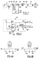
- a pulse tachometer essentially comprises an inductive sensor 10 proximity placed in the vicinity of a rotating member such as a shaft A to generate an electrical pulse 100 to each revolution of this organ, a transmitter 20 connected to this sensor to receive this electrical impulse 100, format it and convert it to a signal optical, a fiber optic link 30 connected to this transmitter and receiver 40 to receive this signal optics from the transmitter and route it to that receiver for its exploitation in order to calculate the speed of the organ.
- the sensor 10 essentially comprises a coil oscillator, a transistorized circuit of shaping treatment and an output stage with an output terminal 102.
- the oscillator coils constitute the sensitive face of the sensor and the oscillator maintains an alternating current there which generates an oscillating magnetic field.
- a metallic part P, or other, associated with the rotating member or shaft moves in the magnetic field in front of the sensor, this inductive magnetic field creates eddy currents or currents induced in this metallic part which then plays the role of the secondary of a transformer in short circuit; this results in an increase in the inductor current supply and stopping the oscillations.
- a transistorized shaping circuit with a fast NPN or PNP transistor output detects the sudden change in current and then delivers a logic signal of constant level, for example 0 or 1 depending on the absence or presence of the metal part.
- Such a logic signal appears on the output stage which preferably includes in particular a demodulator connected to the output of the oscillator.
- the oscillator coils in series are connected in parallel to both two capacitors in series and two resistors in series, and the common terminals of the coils, capacitors and resistors are connected to the inputs of the oscillator.
- the point common to the coils in series and the point common to the capacitors are grounded.
- the point in common with the resistors is connected to the input of the demodulator via an amplifier.
- the transmitter 20 essentially comprises a shaping circuit 21 to lengthen the duration of the electric pulse 100, and a converter 22 for transform the elongated electrical pulse into a signal optical. It also includes an input terminal 201 and a output terminal 202.
- the shaping circuit 21 includes, basically an operational amplifier 211, a diode 212 looping the output of the operational amplifier 211 at its input, and a programmable switch 213 connected in series between diode 212 and the input of the operational amplifier 211.
- the programmable switch 213 includes a electronic switch 2131 and a pilot circuit 2132 who commands it.
- the pilot circuit 2132 includes in particular a first and a second retarder or "timers" preferably combined in the same component 2130.
- the pilot circuit also includes two amplifiers connected to component 2130 and to switch 2131 and which only serve to reverse the impulses so that they are taken into account by either of these components and switches.
- the duration of the state in which the first timer remains is adjusted using an RC mounting, for example zero and a few milliseconds or so and the importance of delay is adjusted using a potentiometer between by example about zero and fifty milliseconds.
- the second timer delivers an "extended" pulse of "width" fixed obtained by RC mounting, for example 1.6 ms, sufficient to command opening of the switch locking the buckle.
- This shaping circuit behaves as a monostable circuit to which a memory effect is introduced by the diode.
- the amplifier output stays low.
- the amplifier output stays high.
- the amplifier output always remains high even if the pulse is passed and the low level produced by the sensor is returned. So we see that the amplifier output remains locked high regardless of the state of the sensor excited or not.
- To unlock the amplifier just open the loop, when there is no pulse from the sensor, using the switch programmable which is controlled by an elongated pulse arriving late compared to the initial impulse of the sensor.
- the amplifier switches and locks at the high state.
- This sensor pulse also triggers the first timer whose output remains high during the adjustable time and with the selected delay.
- the first timer switches after the preset time, it triggers the second timer which delivers the pulse "stretched" of "fixed" width sufficient to order opening the electronic switch locking the loop.
- the delay at the end of which the elongated pulse for example 1.6 ms, is produced after the arrival of the sensor pulse, i.e. less than the minimum period to be measured. If not not the case, the duration of the elongated pulses would be longer as long as the interval between two pulses successive from the sensor.
- the sensor pulse having passed and with the switch open, the amplifier output operational switches back to the low state.
- the switch closes almost immediately but the output of the operational amplifier remains at low since its positive input is low. Then just wait for the impulse to come next to the sensor to repeat the process.
- Converter 22 such as a photodiode transmitter or similar, is supplied by a transistor fast switching whose collector is connected by through a potentiometer.
- the intensity of the emitted light is best adjusted according to characteristics of the fiber optic link, particular of its length.
- the transmitter 20 includes an auxiliary circuit 23 for controlling the occurrence of electrical pulses from the sensor.
- At least one TTL (Transistor-Transistor-Logic) electrical output is used for this, connected to a BNC standardized connector.
- the available output signal can be a rising rising edge or a falling falling edge thanks to an internal selection inverter of the exclusive OR type.
- this auxiliary circuit can have two outputs usable simultaneously output 232 and output 232 '.
- Fiber optic link 30 with one input 301 and an output 302 is established by choosing a fiber adapted to converter 22 so that the attenuation of the fiber is minimum for the wavelength from the converter, for example 6 dB / km.
- a fiber adapted to converter 22 so that the attenuation of the fiber is minimum for the wavelength from the converter, for example 6 dB / km.
- the fiber is protected by a sheath for obtain in particular better mechanical resistance, need suitably adapted to be further “hardened” so that the fiber can be placed where necessary less locally in a hostile environment where reign nuclear radiation.
- the fiber is provided at each of its ends input and output of connectors standardized by example with screwing of the SMA type.
- the receiver 40 is designed to receive the optical signal generated by the transmitter 20 and conveyed by link 30.
- TTL Transistor-Transistor-Logic
- This receiver has an output main where the TTL pulses with edges appear trip amounts and, if applicable, an exit 402 'auxiliary where these inverted pulses appear, with falling falling edges.
- the tachometer is preferably mounted on an adjustable support S such as a micrometric stage a axis (X) for example in order to optimize the signal produced by the sensor by moving the sensor relative to the tree.
- an adjustable support S such as a micrometric stage a axis (X) for example in order to optimize the signal produced by the sensor by moving the sensor relative to the tree.
- Power supplies of all conventional types deliver necessary DC voltages 5V and 12V during operation of the transmitter 20 and the receiver 40. Such power supplies are for example illustrated on Figures 4A and 4B.
- a suitable sensor is one that bears the reference XS4-P08PA340-D in the catalog of the TELEMECANIQUE company.
- a fiber that fits well is one that bears the reference HCP MO200T on the catalog of the ENSIGN-BICKFORD company.
- the tachometer according to the invention implements a circuit to "lengthen” a impetus and which does not require great qualities of speed and stability and the cost of which is therefore reduced.
Landscapes
- Physics & Mathematics (AREA)
- General Physics & Mathematics (AREA)
- Arrangements For Transmission Of Measured Signals (AREA)
- Optical Transform (AREA)
- Catching Or Destruction (AREA)
- Soil Working Implements (AREA)
- Looms (AREA)
Applications Claiming Priority (2)
| Application Number | Priority Date | Filing Date | Title |
|---|---|---|---|
| FR9410533A FR2724230A1 (fr) | 1994-09-01 | 1994-09-01 | Tachymetre perfectionne et son application notamment aux machines tournantes de centrales electriques. |
| FR9410533 | 1994-09-01 |
Publications (2)
| Publication Number | Publication Date |
|---|---|
| EP0699911A1 EP0699911A1 (fr) | 1996-03-06 |
| EP0699911B1 true EP0699911B1 (fr) | 1998-12-23 |
Family
ID=9466639
Family Applications (1)
| Application Number | Title | Priority Date | Filing Date |
|---|---|---|---|
| EP95401987A Expired - Lifetime EP0699911B1 (fr) | 1994-09-01 | 1995-08-31 | Tachymètre perfectionné et son application notamment aux machines tournantes de centrales électriques |
Country Status (6)
| Country | Link |
|---|---|
| US (1) | US5703483A (enExample) |
| EP (1) | EP0699911B1 (enExample) |
| AT (1) | ATE175028T1 (enExample) |
| CA (1) | CA2157338A1 (enExample) |
| DE (1) | DE69506810D1 (enExample) |
| FR (1) | FR2724230A1 (enExample) |
Families Citing this family (2)
| Publication number | Priority date | Publication date | Assignee | Title |
|---|---|---|---|---|
| US8115477B2 (en) * | 2009-04-20 | 2012-02-14 | Electro-Sensors, Inc. | Shaft speed sensor with analog output |
| CN111948177A (zh) * | 2020-07-30 | 2020-11-17 | 季华实验室 | 一种碳化硅外延设备原位监测系统及监测方法 |
Family Cites Families (3)
| Publication number | Priority date | Publication date | Assignee | Title |
|---|---|---|---|---|
| DE3126023A1 (de) * | 1981-07-02 | 1983-01-13 | Volkswagenwerk Ag, 3180 Wolfsburg | "anordnung zur gewinnung einer bewegungsinformation, insbesondere einer drehzahlinformation in einem kraftfahrzeug" |
| DE9014753U1 (de) * | 1990-10-25 | 1991-02-07 | W. Günther GmbH, 8500 Nürnberg | Drehzahl-Meßanordnung |
| US5384534A (en) * | 1992-10-21 | 1995-01-24 | Honeywell Inc. | Self-powered electro-optic rotational position sensor with magnetic pickup |
-
1994
- 1994-09-01 FR FR9410533A patent/FR2724230A1/fr active Granted
-
1995
- 1995-08-31 CA CA002157338A patent/CA2157338A1/fr not_active Abandoned
- 1995-08-31 EP EP95401987A patent/EP0699911B1/fr not_active Expired - Lifetime
- 1995-08-31 DE DE69506810T patent/DE69506810D1/de not_active Expired - Lifetime
- 1995-08-31 US US08/521,983 patent/US5703483A/en not_active Expired - Fee Related
- 1995-08-31 AT AT95401987T patent/ATE175028T1/de not_active IP Right Cessation
Also Published As
| Publication number | Publication date |
|---|---|
| FR2724230A1 (fr) | 1996-03-08 |
| EP0699911A1 (fr) | 1996-03-06 |
| ATE175028T1 (de) | 1999-01-15 |
| US5703483A (en) | 1997-12-30 |
| DE69506810D1 (de) | 1999-02-04 |
| CA2157338A1 (fr) | 1996-03-02 |
| FR2724230B1 (enExample) | 1997-02-14 |
Similar Documents
| Publication | Publication Date | Title |
|---|---|---|
| FR2687864A1 (fr) | Dispositif de detection d'au moins une variable d'etat d'un moteur a courant continu sans balai. | |
| FR2672134A1 (fr) | Ligne a retard optique, dispositif de translation pour un element d'une telle ligne optique et procede de mesure et autocorrelateur utilisant une telle ligne. | |
| FR2811080A1 (fr) | Dispositif de mesure de distorsion de fibre optique | |
| EP0699911B1 (fr) | Tachymètre perfectionné et son application notamment aux machines tournantes de centrales électriques | |
| FR2896593A1 (fr) | Magnetometre de type fluxgate a excitation pulsee et detection echantillonnee | |
| EP0227861A1 (fr) | Procédé de mesure d'une grandeur physique fournissant des données numériques à partir de dispositifs de mesure de valeurs analogiques et appareil de mesure appliquant ce procédé | |
| EP0489651B1 (fr) | Capteur tachymétrique intrinsèque à fibre optique | |
| EP1052519B1 (fr) | Capteur magnétique réalisé sur un substrat semiconducteur | |
| FR2465199A1 (fr) | Procede pour la mise en oeuvre d'un interferometre en anneau comme detecteur de rotation | |
| EP0189732B1 (fr) | Dispositif d'entraînement d'un moteur électrique équipé d'un rotor à alimentation permanente | |
| EP0193453B1 (fr) | Dispositif pour contrôler la période séparant des impulsions | |
| FR2594956A1 (fr) | Dispositif de mesure de la vitesse angulaire d'un corps en rotation | |
| FR2609798A3 (fr) | Circuit en pont pour la detection de l'attitude d'un vehicule | |
| FR2664972A1 (fr) | Capteur de deplacement a circuit oscillant couple magnetiquement a une cible conductrice. | |
| FR2520123A1 (fr) | Dispositif d'autotest pour equiper un systeme optronique | |
| EP0511119B1 (fr) | Capteur de vibrations à fibre optique et accéléromètre utilisant un tel capteur | |
| FR2656702A1 (fr) | Detecteur de champ magnetique. | |
| FR2561001A1 (fr) | Capteur de la position relative d'une cible par rapport a une cible de reference | |
| FR2507782A1 (fr) | Tachymetre pour un dispositif electrique a commutation, en particulier pour un moteur electrique | |
| FR2488398A1 (fr) | Debitmetre electromagnetique | |
| FR2622974A1 (fr) | Dispositif de detection et de mesure des oscillations hyposynchrones d'un arbre,notamment d'un arbre d'un groupe turbo-alternateur | |
| EP0370839B1 (fr) | Dispositif pour la mesure de la position angulaire et du déplacement linéaire de deux pièces l'une par rapport à l'autre | |
| FR2908246A1 (fr) | Moteur electrique a courant continu et procede de controle de la position angulaire d'un tel moteur | |
| FR2696599A1 (fr) | Contacts auxiliaires pour appareil électrique. | |
| FR2795885A1 (fr) | Methode de calage d'un moteur electrique de type polyphase a fonctionnement pas a pas, ceci par rapport a une position de reference correspondant a une butee mecanique |
Legal Events
| Date | Code | Title | Description |
|---|---|---|---|
| PUAI | Public reference made under article 153(3) epc to a published international application that has entered the european phase |
Free format text: ORIGINAL CODE: 0009012 |
|
| AK | Designated contracting states |
Kind code of ref document: A1 Designated state(s): AT BE CH DE DK ES FR GB GR IE IT LI LU MC NL PT SE |
|
| 17P | Request for examination filed |
Effective date: 19960315 |
|
| 17Q | First examination report despatched |
Effective date: 19971114 |
|
| GRAG | Despatch of communication of intention to grant |
Free format text: ORIGINAL CODE: EPIDOS AGRA |
|
| GRAG | Despatch of communication of intention to grant |
Free format text: ORIGINAL CODE: EPIDOS AGRA |
|
| GRAH | Despatch of communication of intention to grant a patent |
Free format text: ORIGINAL CODE: EPIDOS IGRA |
|
| GRAH | Despatch of communication of intention to grant a patent |
Free format text: ORIGINAL CODE: EPIDOS IGRA |
|
| GRAA | (expected) grant |
Free format text: ORIGINAL CODE: 0009210 |
|
| AK | Designated contracting states |
Kind code of ref document: B1 Designated state(s): AT BE CH DE DK ES FR GB GR IE IT LI LU MC NL PT SE |
|
| PG25 | Lapsed in a contracting state [announced via postgrant information from national office to epo] |
Ref country code: NL Free format text: LAPSE BECAUSE OF FAILURE TO SUBMIT A TRANSLATION OF THE DESCRIPTION OR TO PAY THE FEE WITHIN THE PRESCRIBED TIME-LIMIT Effective date: 19981223 Ref country code: IT Free format text: LAPSE BECAUSE OF FAILURE TO SUBMIT A TRANSLATION OF THE DESCRIPTION OR TO PAY THE FEE WITHIN THE PRE;WARNING: LAPSES OF ITALIAN PATENTS WITH EFFECTIVE DATE BEFORE 2007 MAY HAVE OCCURRED AT ANY TIME BEFORE 2007. THE CORRECT EFFECTIVE DATE MAY BE DIFFERENT FROM THE ONE RECORDED.SCRIBED TIME-LIMIT Effective date: 19981223 Ref country code: GR Free format text: LAPSE BECAUSE OF NON-PAYMENT OF DUE FEES Effective date: 19981223 Ref country code: GB Free format text: LAPSE BECAUSE OF NON-PAYMENT OF DUE FEES Effective date: 19981223 Ref country code: ES Free format text: THE PATENT HAS BEEN ANNULLED BY A DECISION OF A NATIONAL AUTHORITY Effective date: 19981223 Ref country code: AT Free format text: LAPSE BECAUSE OF FAILURE TO SUBMIT A TRANSLATION OF THE DESCRIPTION OR TO PAY THE FEE WITHIN THE PRESCRIBED TIME-LIMIT Effective date: 19981223 |
|
| REF | Corresponds to: |
Ref document number: 175028 Country of ref document: AT Date of ref document: 19990115 Kind code of ref document: T |
|
| REG | Reference to a national code |
Ref country code: CH Ref legal event code: EP |
|
| REF | Corresponds to: |
Ref document number: 69506810 Country of ref document: DE Date of ref document: 19990204 |
|
| REG | Reference to a national code |
Ref country code: IE Ref legal event code: FG4D Free format text: FRENCH |
|
| PG25 | Lapsed in a contracting state [announced via postgrant information from national office to epo] |
Ref country code: SE Free format text: LAPSE BECAUSE OF FAILURE TO SUBMIT A TRANSLATION OF THE DESCRIPTION OR TO PAY THE FEE WITHIN THE PRESCRIBED TIME-LIMIT Effective date: 19990323 Ref country code: PT Free format text: LAPSE BECAUSE OF FAILURE TO SUBMIT A TRANSLATION OF THE DESCRIPTION OR TO PAY THE FEE WITHIN THE PRESCRIBED TIME-LIMIT Effective date: 19990323 Ref country code: DK Free format text: LAPSE BECAUSE OF FAILURE TO SUBMIT A TRANSLATION OF THE DESCRIPTION OR TO PAY THE FEE WITHIN THE PRESCRIBED TIME-LIMIT Effective date: 19990323 |
|
| PG25 | Lapsed in a contracting state [announced via postgrant information from national office to epo] |
Ref country code: DE Free format text: LAPSE BECAUSE OF FAILURE TO SUBMIT A TRANSLATION OF THE DESCRIPTION OR TO PAY THE FEE WITHIN THE PRESCRIBED TIME-LIMIT Effective date: 19990324 |
|
| NLV1 | Nl: lapsed or annulled due to failure to fulfill the requirements of art. 29p and 29m of the patents act | ||
| GBV | Gb: ep patent (uk) treated as always having been void in accordance with gb section 77(7)/1977 [no translation filed] |
Effective date: 19981223 |
|
| PGFP | Annual fee paid to national office [announced via postgrant information from national office to epo] |
Ref country code: FR Payment date: 19990726 Year of fee payment: 5 |
|
| PG25 | Lapsed in a contracting state [announced via postgrant information from national office to epo] |
Ref country code: IE Free format text: LAPSE BECAUSE OF NON-PAYMENT OF DUE FEES Effective date: 19990820 |
|
| PG25 | Lapsed in a contracting state [announced via postgrant information from national office to epo] |
Ref country code: LU Free format text: LAPSE BECAUSE OF NON-PAYMENT OF DUE FEES Effective date: 19990831 Ref country code: LI Free format text: LAPSE BECAUSE OF NON-PAYMENT OF DUE FEES Effective date: 19990831 Ref country code: CH Free format text: LAPSE BECAUSE OF NON-PAYMENT OF DUE FEES Effective date: 19990831 Ref country code: BE Free format text: LAPSE BECAUSE OF NON-PAYMENT OF DUE FEES Effective date: 19990831 |
|
| REG | Reference to a national code |
Ref country code: IE Ref legal event code: FD4D |
|
| PLBE | No opposition filed within time limit |
Free format text: ORIGINAL CODE: 0009261 |
|
| STAA | Information on the status of an ep patent application or granted ep patent |
Free format text: STATUS: NO OPPOSITION FILED WITHIN TIME LIMIT |
|
| 26N | No opposition filed | ||
| BERE | Be: lapsed |
Owner name: ELECTRICITE DE FRANCE SERVICE NATIONAL Effective date: 19990831 |
|
| PG25 | Lapsed in a contracting state [announced via postgrant information from national office to epo] |
Ref country code: MC Free format text: LAPSE BECAUSE OF NON-PAYMENT OF DUE FEES Effective date: 20000229 |
|
| REG | Reference to a national code |
Ref country code: CH Ref legal event code: PL |
|
| PG25 | Lapsed in a contracting state [announced via postgrant information from national office to epo] |
Ref country code: FR Free format text: LAPSE BECAUSE OF NON-PAYMENT OF DUE FEES Effective date: 20010430 |
|
| REG | Reference to a national code |
Ref country code: FR Ref legal event code: ST |