EP0699791A1 - Method of forming a knot on a flat knitting machine - Google Patents
Method of forming a knot on a flat knitting machine Download PDFInfo
- Publication number
- EP0699791A1 EP0699791A1 EP95306138A EP95306138A EP0699791A1 EP 0699791 A1 EP0699791 A1 EP 0699791A1 EP 95306138 A EP95306138 A EP 95306138A EP 95306138 A EP95306138 A EP 95306138A EP 0699791 A1 EP0699791 A1 EP 0699791A1
- Authority
- EP
- European Patent Office
- Prior art keywords
- needle
- knot
- stitch
- yarn
- empty
- Prior art date
- Legal status (The legal status is an assumption and is not a legal conclusion. Google has not performed a legal analysis and makes no representation as to the accuracy of the status listed.)
- Granted
Links
- 238000009940 knitting Methods 0.000 title claims abstract description 58
- 238000000034 method Methods 0.000 title claims description 15
- 239000004744 fabric Substances 0.000 claims abstract description 28
- 238000009963 fulling Methods 0.000 claims description 4
- 230000015572 biosynthetic process Effects 0.000 description 18
- 238000010586 diagram Methods 0.000 description 12
- 230000002452 interceptive effect Effects 0.000 description 1
- 230000000717 retained effect Effects 0.000 description 1
Images


Classifications
-
- D—TEXTILES; PAPER
- D04—BRAIDING; LACE-MAKING; KNITTING; TRIMMINGS; NON-WOVEN FABRICS
- D04B—KNITTING
- D04B1/00—Weft knitting processes for the production of fabrics or articles not dependent on the use of particular machines; Fabrics or articles defined by such processes
- D04B1/10—Patterned fabrics or articles
- D04B1/12—Patterned fabrics or articles characterised by thread material
- D04B1/126—Patterned fabrics or articles characterised by thread material with colour pattern, e.g. intarsia fabrics
-
- D—TEXTILES; PAPER
- D04—BRAIDING; LACE-MAKING; KNITTING; TRIMMINGS; NON-WOVEN FABRICS
- D04B—KNITTING
- D04B1/00—Weft knitting processes for the production of fabrics or articles not dependent on the use of particular machines; Fabrics or articles defined by such processes
- D04B1/06—Non-run fabrics or articles
Definitions
- the present invention relates to a method of forming a knot with the use of a flat knitting machine.
- One object of the present invention is to provide a new method of forming a knot on a flat knitting machine.
- Another object of the present invention is to form a knot with minimal courses.
- Another object of the present invention is to make a knot inconspicuous.
- Still another object of the present invention is to hold a knot in any desired position.
- the present invention uses a flat knitting machine which has at least a pair of needle beds abutting to each other, which is capable of transferring a yarn between needle beds, and which is capable of racking needle beds relative to each other, and is characterized by the following steps,
- a yarn is fed to an empty needle, the yarn is hooked by the needle, then the yarn feeder is reversed to change the direction of the yarn, and the yarn is transferred to the opposite bed.
- the hooked yarn forms a loop.
- a next stitch is produced on the formed loop, then the loop is knocked over to form a knot in the lower part of the stitch.
- the knot is placed over a stitch of the knitted fabric, and the knot is held to the knitted fabric by another course. The number of courses needed is small, and the knot is formed by minimal courses.
- a knot can be formed by a minimal number of courses.
- the knot after the prolongation is tightened and cut off, is sunken beneath the other stitch placed over the knot, and is inconspicuous; thus a clear pattern boundary can be formed on the knitted fabric.
- the knot may be held in any places other than the boundary of a pattern. When the knot is located inside the pattern, the knot does not disturb the pattern.
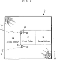
- Fig. 1 A diagram showing the point at which a new yarn is introduced and the point at which the yarn is terminated in an embodiment. The diagram also shows knitting areas P, Q and R.
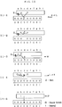
- Fig. 2 and Fig. 3 Knitting course diagrams showing the formation of a knot for introducing a new yarn.
- a through I in the diagrams show needles of a front bed, and a through i show needles of a back bed.
- 1P indicates a racking by one pitch.
- the needles A through C corresponds to the knitting area Q, needles D through F to the knitting area P, and needles G through I to the knitting area R, respectively.
- Fig. 2-1 shows a stitch row of the area Q being held on needles A through I.
- Fig. 2-2 shows transferring a stitch on the needle D to the needle d.
- Fig. 2-3 shows hooking the yarn of the knitting area P on the needle D.
- Fig. 2-4 shows reversing the yarn feeder.
- Fig. 3-1 shows formation of a stitch by transferring the yarn being hooked on the needle D to the needle c.
- Fig. 3-2 shows retransferring the stitch from the needle d to the needle D.
- Fig. 3-3 shows formation of a new stitch on the needle c and formation of a knot from the original stitch.
- Fig. 3-4 shows overlapping the formed knot with the stitch on the needle D.
- Fig. 4 The diagrams show the formation of a knot by the knitting courses shown in Fig. 2 and Fig. 3.
- Fig. 4-1 corresponds to Fig. 2-3.
- Fig. 4-2 corresponds to Fig. 2-4.
- Fig. 4-3 corresponds to Fig. 3-1.
- Fig. 4-4 corresponds to Fig. 3-3.
- Fig. 5 A partial diagram showing loops after the introduction of a yarn in the embodiment.
- Fig. 6 and Fig. 7 Knitting course diagrams showing the formation of a knot for terminating a yarn in the embodiment.
- Fig. 6-1 shows knitting the last course of the area P.
- Fig. 6-2 shows transferring a stitch on the needle D to the needle d.
- Fig. 6-3 shows hooking the yarn on the needle D.
- Fig. 6-4 shows reversing the yarn feeder.
- Fig. 7-1 shows formation of a stitch by transferring the yarn being hooked on the needle D to the needle c.
- Fig. 7-2 shows retransferring the stitch from the needle d to the needle D.
- Fig. 7-3 shows formation of a new stitch on the needle c and formation of a knot from the original stitch.
- Fig. 7-4 shows overlapping the formed knot with the stitch on the needle D.
- Fig. 8 The diagrams show the formation of a knot by the knitting courses shown in Fig. 6 and Fig. 7.
- Fig. 8-1 corresponds to Fig. 6-3.
- Fig. 8-2 corresponds to Fig. 6-4.
- Fig. 8-3 corresponds to Fig. 7-1.
- Fig. 8-4 corresponds to Fig. 7-3.
- Fig. 9 A partial diagram showing loops after the termination of the yarn in the embodiment.
- Fig. 10 Knitting course diagrams showing the formation of a knot for introducing a new yarn in an optimal embodiment.
- Fig. 10-1 follows Fig. 2-3 and shows hooking the yarn on the needle D and tacking the yarn to the needle b.
- Fig. 10-2 shows transferring the stitch on the needle D to the needle c.
- Fig. 10-3 shows retransferring the stitch from the needle d to the needle D.
- Fig. 10-4 shows formation of a knot by forming a new stitch on the needle c.
- Fig. 10-5 shows transferring the knot to the needle D and the treatment of the yarn being tacked to the needle b.
- Fig. 11 Knitting course diagrams showing the formation of a knot for terminating a yarn in the optimal embodiment.
- Fig. 11-1 follows Fig. 6-3, and shows hooking the yarn on the needle D and tacking to the needle b.
- Fig. 11-2 shows transferring from the needle D to the needle c.
- Fig. 11-3 shows retransferring the stitch from the needle d to the needle D.
- Fig. 11-4 shows formation of a knot by forming a new stitch on the needle c.
- Fig. 11-5 shows shifting the knot to the needle D and treatment of the yarn tacked to the needle b.
- Fig. 1 through Fig. 9 show an embodiment.
- the embodiment shows both the introduction of a yarn and the termination of a yarn.
- the embodiment may be applied to either the introduction of a yarn or the termination of a yarn.
- a knitted fabric 1 having three knitting areas P, Q and R is to be intarsia-knitted.
- the first color is allotted to the area P, and the second color is allotted to the areas Q and R.
- different yarns of the same color are allotted to the areas Q and R.
- the introduction of a yarn and the termination of the yarn are needed at the starting points and finishing points of the respective knitting areas P, Q and R.
- One knot is needed for every introduction or termination of a yarn.
- the present embodiment shows formation of a knot at the starting point and at the terminating point of the knitting area P.
- Fig. 1 denotes a stitch of the area Q, the stitch being immediately before the area P.
- 8 denotes a knot of the yarn introducing part of the area P, the knot overlapping with the stitch 3.
- 4 is a prolongation from the knot 8 to a yarn end holder not illustrated.
- 11 is a stitch of the last course of the area P.
- 16 is a knot of the yarn terminating part, the knot overlapping with the stitch 11.
- 18 is a prolongation from the knot 16.
- the knitting proceeds from the bottom end of Fig. 1 in the direction of the arrow U, and the area Q is knitted just immediately before the area P and the area R.
- each diagram shows a smaller number of needles than those actually used.
- A, B, C, ... indicate needles of the front bed.
- a, b, c, ... indicate needles of the back bed.
- the case of introducing a yarn is shown in Fig. 2 and Fig. 3.
- the needle beds are in the state shown in Fig. 2-1.
- a stitch of the needle D is transferred to the needle d of the opposing bed.
- the back bed is racked, for example, by a pitch of one needle in the direction away from the prolongation 4.
- the yarn feeder 2 is moved to feed a yarn 5 to the empty needle D.
- the yarn 5 is hooked on the needle D (Fig. 4-1). Feeding a yarn to an empty needle is called empty needle knitting, and the hooked yarn is assumed to be a stitch and is called a stitch of empty needle knitting.
- the yarn feeder 2 is reversed to feed the yarn to the needle c.
- the yarn 5 being located beneath the prolongation 4 is turned back to go over the prolongation 4, and a stitch 7 is formed on the needle c by knitting operation.
- the stitch 6 of empty needle knitting is knocked over from the needle c, and a knot 8 is formed by the stitch 7 and the stitch 6 of empty needle knitting (Fig. 4-4).
- the back bed is racked towards the right by one needle, then the knot 8 is transferred, for example, to the needle D.
- the stitch 7 is overlapped with the stitch 3 of the area Q to form a double stitch.
- the yarn is fed from the yarn feeder 2 to the needles D through F of the front bed to knit the area P.
- the knot is fixed onto the knitted fabric.
- the state of the knot 8 after knitting the area P is shown in Fig. 5.
- the knot 8 overlaps with the stitch 3, and is retained in position by a stitch 9 of the first course of the area P.
- the knitted fabric 1 is removed from the flat knitting machine.
- the prolongation 4 is pulled out and the knot 4 is tightened. Then the prolongation 4 is cut off near the knitted fabric. Thus the treatment of the yarn introducing part is completed.
- One of the important points in forming the knot 8 is the formation of a loop by empty-needle-knitting on an empty needle, reversing the yarn feeder to change the direction of the yarn, and transferring the stitch to the opposite bed. Then the next knit stitch is formed on the loop formed, and the above-mentioned loop is knocked over to form a knot in the lower part of the knit stitch. Next, the knot is overlapped with a stitch of the knitted fabric, and in a subsequent course, the knot is held onto the knitted fabric.
- the required number of courses is small as clearly shown in Fig. 2 and Fig. 3. Thus with a minimal number of courses, a knot can be formed.
- the knot 8 is inconspicuous, and the boundary of the pattern can be seen clearly.
- the knot 8 can be made to overlap with any stitch desired. For instance, after the formation of the knot 8, an appropriate number of courses of the area 8 may be knitted, and the knot 8 may be made to overlap with a stitch of the area P. In this case, the knot 8 overlaps with a stitch of the same color, and the pattern of the knitted fabric 1 can be seen more clearly.
- the knot 8 may be formed, for example, several courses before the start of knitting the area P, the formed knot 8 may be held on a needle which is not used in knitting, and later the knot 8 may be made to overlap with a stitch of the area P.
- the yarn feeder 2 is reversed, and as shown in Fig. 8-2, the yarn feeder 2 is shifted to the left beyond the needle D.
- the stitch of empty-needle knitting on the needle D is transferred to the opposing needle c.
- the transferred state is shown in Fig. 8-3; the prolongation from the stitch 11 to the needle c is located above the yarn 12, and the stitch of empty-needle-knitting is twisted to form a loop 14.
- the back bed is racked to the left by one needle, then the stitch 11 on the needle d is transferred back to the needle D.
- the yarn feeder 2 is reversed, and the yarn 12 is fed to the needle c on which the loop 14 is hooked.
- the yarn 12 lying beneath the prolongation 13 is folded back and goes over the prolongation 13 to form a stitch 15 by knitting operation.
- the loop 14 is knocked over and a knot 16 is formed at the root of the stitch 15.
- the back bed is racked to the right by one needle.
- the stitch 15 is transferred, for example, to the needle D, and the knot 16 is made to overlap with the stitch 11 to form a double stitch.
- a stitch 17 of the area Q shown in Fig. 9 is formed on the double stitch to hold the double stitch onto the knitted fabric.
- the state of the knot 16 and around are shown in Fig. 9.
- the knitted fabric 1 is removed from the flat knitting machine. Then the prolongation 18 between the yarn end and the knitted fabric is pulled out from the knitted fabric 1. The knot 16 is tightened up, and the prolongation 18 is cut off near the knot 16.
- the present invention is not limited to knitting of intarsia knitted fabrics. For instance, it may be applied to yarn introduction and yarn termination for forming a pocket on a body part.
- the explanation was given for a flat knitting machine having two beds.
- a flat knitting machine with four beds for example, a knitted fabric is knitted on a front lower bed, and empty-needle-knitting is made on a front upper bed. Stitches of empty-needle-knitting are transferred to a remaining back upper bed or a remaining back lower bed.
- the courses of Fig. 2-1, Fig. 2-2, Fig. 6-1 and Fig. 6-2 can be eliminated.
- FIG. 10 and Fig. 11 An optimal embodiment is shown in Fig. 10 and Fig. 11. If the loop 6 or 14 held on the needle c comes to the top end of the hook of the needle c, it is hard to form knot 8 or 16. Hence, in the present embodiment, to prevent the loop 6 or 14 from coming to the top end of the hook, tucking is made to the nearby needle b. When the knot 8 or 16 is transferred back to the needle D, the tucked stitch is removed. The knot thus obtained is identical to the knot 8 or 16 of the embodiment of Fig. 2 through Fig. 9.
- Fig. 10-1 through Fig. 10-5 show the yarn introducing processes. After the processes up to those of Fig. 2-3 are completed, tucking is made to the needle b in the course of Fig. 10-1. In the next course of Fig. 10-2, the stitch of empty-needle-knitting of the needle D is transferred to the needle c, and in the next course of Fig. 10-3, the stitch on the needle d is transferred back to the original needle D. Next, in the course of Fig. 10-4, the stitch 7 is formed on the needle c to from the knot 8, and in the course of Fig. 10-5, the knot 8 is made to overlap with the stitch 3 on the needle D, and at the same time, the stitch being tucked to the needle b is removed. Other points are similar to those of the embodiment of Fig. 2 through Fig. 5.
- Fig. 11-1 through Fig. 11-5 show the processes of yarn termination. After the processes of up to Fig. 6-3 are completed, in the course of Fig. 11-1, tucking is made to the needle b. In the next course of Fig. 11-2, the stitch of empty-needle-knitting on the needle D is transferred to the needle c. In the next course of Fig. 11-3, the stitch on the needle d is transferred back to the original needle D. In the next course of Fig. 11-5, the knot 8 is made to overlap with the stitch 3 on the needle D, and at the same time, the stitch being tucked to the needle b is removed. Other points are similar to those of the embodiment of Fig. 6 through Fig. 9. The treatment is similar to the yarn introduction of Fig. 10 except there is no prolongation but there is a knot 11 in place of it.
Abstract
Description
- The present invention relates to a method of forming a knot with the use of a flat knitting machine.
- In producing knitted fabrics with a flat knitting machine, it is necessary to form a knot to prevent knitted fabrics from running every time when a new yarn is used for knitting or when knitting with one specific yarn is completed. The formation of a knot is done manually and is inefficient. EP-A-616064, which was published after the priority date of the present invention, discloses knitting courses for forming stitches on a flat knitting machine.
- One object of the present invention is to provide a new method of forming a knot on a flat knitting machine.
- Another object of the present invention is to form a knot with minimal courses.
- Another object of the present invention is to make a knot inconspicuous.
- Still another object of the present invention is to hold a knot in any desired position.
- The present invention uses a flat knitting machine which has at least a pair of needle beds abutting to each other, which is capable of transferring a yarn between needle beds, and which is capable of racking needle beds relative to each other, and is characterized by the following steps,
- a: a step of feeding a yarn from a yarn feeder to an empty needle of one needle bed and hooking the yarn by said needle;
- b: a step of reversing the yarn feeder and shifting the yarn feeder beyond said needle;
- c: a step of transferring the yarn being hooked by said needle to an empty needle of another needle bed to form a loop;
- d: a step of feeding the yarn from the yarn feeder to said needle to which transfer was made to form a stitch, and of knocking over said transferred loop to form a knot;
- e: a step of overlapping said knot with a stitch of the knitted fabric to make a double stitch; and
- f: a step of forming another stitch on said double stitch to fix said knot onto the knitted fabric.
- In the present invention, a yarn is fed to an empty needle, the yarn is hooked by the needle, then the yarn feeder is reversed to change the direction of the yarn, and the yarn is transferred to the opposite bed. As a result, the hooked yarn forms a loop. A next stitch is produced on the formed loop, then the loop is knocked over to form a knot in the lower part of the stitch. In the subsequent steps, the knot is placed over a stitch of the knitted fabric, and the knot is held to the knitted fabric by another course. The number of courses needed is small, and the knot is formed by minimal courses.
- As described above, a knot can be formed by a minimal number of courses. The knot, after the prolongation is tightened and cut off, is sunken beneath the other stitch placed over the knot, and is inconspicuous; thus a clear pattern boundary can be formed on the knitted fabric. Moreover, the knot may be held in any places other than the boundary of a pattern. When the knot is located inside the pattern, the knot does not disturb the pattern.
- A number of preferred embodiments of the present invention will now be described by way of example only and with reference to the accompanying drawings, in which:-
- Fig. 1: A diagram showing the point at which a new yarn is introduced and the point at which the yarn is terminated in an embodiment. The diagram also shows knitting areas P, Q and R.
- Fig. 2 and Fig. 3: Knitting course diagrams showing the formation of a knot for introducing a new yarn. A through I in the diagrams show needles of a front bed, and a through i show needles of a back bed. 1P indicates a racking by one pitch. The needles A through C corresponds to the knitting area Q, needles D through F to the knitting area P, and needles G through I to the knitting area R, respectively.
- Fig. 2-1 shows a stitch row of the area Q being held on needles A through I.
- Fig. 2-2 shows transferring a stitch on the needle D to the needle d.
- Fig. 2-3 shows hooking the yarn of the knitting area P on the needle D.
- Fig. 2-4 shows reversing the yarn feeder. Fig. 3-1 shows formation of a stitch by transferring the yarn being hooked on the needle D to the needle c.
- Fig. 3-2 shows retransferring the stitch from the needle d to the needle D.
- Fig. 3-3 shows formation of a new stitch on the needle c and formation of a knot from the original stitch.
- Fig. 3-4 shows overlapping the formed knot with the stitch on the needle D.
- Fig. 4: The diagrams show the formation of a knot by the knitting courses shown in Fig. 2 and Fig. 3.
- Fig. 4-1 corresponds to Fig. 2-3.
- Fig. 4-2 corresponds to Fig. 2-4.
- Fig. 4-3 corresponds to Fig. 3-1.
- Fig. 4-4 corresponds to Fig. 3-3.
- Fig. 5: A partial diagram showing loops after the introduction of a yarn in the embodiment.
- Fig. 6 and Fig. 7: Knitting course diagrams showing the formation of a knot for terminating a yarn in the embodiment.
- Fig. 6-1 shows knitting the last course of the area P.
- Fig. 6-2 shows transferring a stitch on the needle D to the needle d.
- Fig. 6-3 shows hooking the yarn on the needle D.
- Fig. 6-4 shows reversing the yarn feeder.
- Fig. 7-1 shows formation of a stitch by transferring the yarn being hooked on the needle D to the needle c.
- Fig. 7-2 shows retransferring the stitch from the needle d to the needle D.
- Fig. 7-3 shows formation of a new stitch on the needle c and formation of a knot from the original stitch.
- Fig. 7-4 shows overlapping the formed knot with the stitch on the needle D.
- Fig. 8: The diagrams show the formation of a knot by the knitting courses shown in Fig. 6 and Fig. 7.
- Fig. 8-1 corresponds to Fig. 6-3.
- Fig. 8-2 corresponds to Fig. 6-4.
- Fig. 8-3 corresponds to Fig. 7-1.
- Fig. 8-4 corresponds to Fig. 7-3.
- Fig. 9: A partial diagram showing loops after the termination of the yarn in the embodiment.
- Fig. 10: Knitting course diagrams showing the formation of a knot for introducing a new yarn in an optimal embodiment.
- Fig. 10-1 follows Fig. 2-3 and shows hooking the yarn on the needle D and tacking the yarn to the needle b.
- Fig. 10-2 shows transferring the stitch on the needle D to the needle c.
- Fig. 10-3 shows retransferring the stitch from the needle d to the needle D.
- Fig. 10-4 shows formation of a knot by forming a new stitch on the needle c.
- Fig. 10-5 shows transferring the knot to the needle D and the treatment of the yarn being tacked to the needle b.
- Fig. 11: Knitting course diagrams showing the formation of a knot for terminating a yarn in the optimal embodiment.
- Fig. 11-1 follows Fig. 6-3, and shows hooking the yarn on the needle D and tacking to the needle b.
- Fig. 11-2 shows transferring from the needle D to the needle c.
- Fig. 11-3 shows retransferring the stitch from the needle d to the needle D.
- Fig. 11-4 shows formation of a knot by forming a new stitch on the needle c.
- Fig. 11-5 shows shifting the knot to the needle D and treatment of the yarn tacked to the needle b.
- Fig. 1 through Fig. 9 show an embodiment. The embodiment shows both the introduction of a yarn and the termination of a yarn. The embodiment may be applied to either the introduction of a yarn or the termination of a yarn. As shown in Fig. 1, a
knitted fabric 1 having three knitting areas P, Q and R is to be intarsia-knitted. The first color is allotted to the area P, and the second color is allotted to the areas Q and R. For intarsia-knitting, different yarns of the same color are allotted to the areas Q and R. The introduction of a yarn and the termination of the yarn are needed at the starting points and finishing points of the respective knitting areas P, Q and R. One knot is needed for every introduction or termination of a yarn. The present embodiment shows formation of a knot at the starting point and at the terminating point of the knitting area P. - In Fig. 1, 3 denotes a stitch of the area Q, the stitch being immediately before the area P. 8 denotes a knot of the yarn introducing part of the area P, the knot overlapping with the
stitch 3. 4 is a prolongation from theknot 8 to a yarn end holder not illustrated. 11 is a stitch of the last course of the area P. 16 is a knot of the yarn terminating part, the knot overlapping with thestitch 11. 18 is a prolongation from theknot 16. The knitting proceeds from the bottom end of Fig. 1 in the direction of the arrow U, and the area Q is knitted just immediately before the area P and the area R. - For the convenience of description, each diagram shows a smaller number of needles than those actually used. A, B, C, ... indicate needles of the front bed. a, b, c, ... indicate needles of the back bed. The case of introducing a yarn is shown in Fig. 2 and Fig. 3. Just when knitting of the
stitch 3 is completed, the needle beds are in the state shown in Fig. 2-1. During the course shown in Fig. 2-2, for example, a stitch of the needle D is transferred to the needle d of the opposing bed. In the next course shown in Fig. 2-3, the back bed is racked, for example, by a pitch of one needle in the direction away from theprolongation 4. Then theyarn feeder 2 is moved to feed ayarn 5 to the empty needle D. As a result, theyarn 5 is hooked on the needle D (Fig. 4-1). Feeding a yarn to an empty needle is called empty needle knitting, and the hooked yarn is assumed to be a stitch and is called a stitch of empty needle knitting. - In the next course of Fig. 2-4, the
yarn feeder 2 is reversed and moved to the left side of the needle D. As a result, the condition of the yarn on the needle D becomes as shown in Fig. 4-2. Next, in the course as shown in Fig, 3-1, the stitch of the empty needle knitting on the needle D is transferred to the needle c. Then, as a result of the transfer, theprolongation 4 is located above theyarn 5. Thus the stitch of the empty needle knitting is twisted to form a loop 6 (Fig. 4-3). In the next course as shown in Fig. 3-2, the back bed is racked towards the left by one needle, then thestitch 3 is transferred from the needle d back to the needle D. Then, in the next course as shown in Fig. 3-3, theyarn feeder 2 is reversed to feed the yarn to the needle c. In this process, theyarn 5 being located beneath theprolongation 4 is turned back to go over theprolongation 4, and a stitch 7 is formed on the needle c by knitting operation. At the same time, thestitch 6 of empty needle knitting is knocked over from the needle c, and aknot 8 is formed by the stitch 7 and thestitch 6 of empty needle knitting (Fig. 4-4). - Next, in the course as shown in Fig. 3-4, the back bed is racked towards the right by one needle, then the
knot 8 is transferred, for example, to the needle D. As a result, the stitch 7 is overlapped with thestitch 3 of the area Q to form a double stitch. After that, the yarn is fed from theyarn feeder 2 to the needles D through F of the front bed to knit the area P. When a stitch of the next course of the area P is formed on the double stitch comprising thestitch 3 and the stitch 7, the knot is fixed onto the knitted fabric. - The state of the
knot 8 after knitting the area P is shown in Fig. 5. Theknot 8 overlaps with thestitch 3, and is retained in position by astitch 9 of the first course of the area P. Theknitted fabric 1 is removed from the flat knitting machine. Theprolongation 4 is pulled out and theknot 4 is tightened. Then theprolongation 4 is cut off near the knitted fabric. Thus the treatment of the yarn introducing part is completed. - One of the important points in forming the
knot 8 is the formation of a loop by empty-needle-knitting on an empty needle, reversing the yarn feeder to change the direction of the yarn, and transferring the stitch to the opposite bed. Then the next knit stitch is formed on the loop formed, and the above-mentioned loop is knocked over to form a knot in the lower part of the knit stitch. Next, the knot is overlapped with a stitch of the knitted fabric, and in a subsequent course, the knot is held onto the knitted fabric. The required number of courses is small as clearly shown in Fig. 2 and Fig. 3. Thus with a minimal number of courses, a knot can be formed. - When the
prolongation 4 is cut off, as the stitch 7 has been tightened up, the stitch 7 sets beneath thestitch 3. Thus thestitch 3 comes to the surface of theknitted fabric 1. As a result, theknot 8 is inconspicuous, and the boundary of the pattern can be seen clearly. Theknot 8 can be made to overlap with any stitch desired. For instance, after the formation of theknot 8, an appropriate number of courses of thearea 8 may be knitted, and theknot 8 may be made to overlap with a stitch of the area P. In this case, theknot 8 overlaps with a stitch of the same color, and the pattern of theknitted fabric 1 can be seen more clearly. Theknot 8 may be formed, for example, several courses before the start of knitting the area P, the formedknot 8 may be held on a needle which is not used in knitting, and later theknot 8 may be made to overlap with a stitch of the area P. - With reference to Fig. 6 through Fig. 9, the termination of the yarn will be explained. In the case of yarn introduction, when a stitch once transferred to the needle d is to be transferred back to the needle D, it is necessary to keep the
prolongation 4 from interfering the process. Hence the back bed has to be racked towards the left in Fig. 2-3. In the case of yarn termination, however, there is no need of considering the prolongation from the yarn feeder. Thus racking can be made in either direction. Suppose theknitted fabric 1 of Fig. 1 has been knitted up to thelast stitch 11 of the area P. At that point, as shown in Fig. 6-1, the stitches of the area Q are hooked on the needles A through C, the stitches of the area P on the needles D through F, and the stitches of the area R on the needles G through I, respectively. Next, in the course of Fig. 6-2, thestitch 11 held on the needle D is transferred to the needle d. Next, in the course of Fig. 6-3, the back bed is racked towards the right by, for example, one needle. Then ayarn 12 is fed from theyarn feeder 2 to the empty needle D. 13 is a prolongation to the stitch held on the needle d. The stitch of empty-needle-knitting thus obtained is shown in Fig. 8-1. - Next, in the course as shown in Fig. 6-4, the
yarn feeder 2 is reversed, and as shown in Fig. 8-2, theyarn feeder 2 is shifted to the left beyond the needle D. In the course of the next Fig. 7-1, the stitch of empty-needle knitting on the needle D is transferred to the opposing needle c. The transferred state is shown in Fig. 8-3; the prolongation from thestitch 11 to the needle c is located above theyarn 12, and the stitch of empty-needle-knitting is twisted to form aloop 14. - Next, in the course of Fig. 7-2, the back bed is racked to the left by one needle, then the
stitch 11 on the needle d is transferred back to the needle D. In the course of the next Fig. 7-3, theyarn feeder 2 is reversed, and theyarn 12 is fed to the needle c on which theloop 14 is hooked. At this time, theyarn 12 lying beneath theprolongation 13 is folded back and goes over theprolongation 13 to form astitch 15 by knitting operation. As a result, theloop 14 is knocked over and aknot 16 is formed at the root of thestitch 15. In the course of the next Fig. 7-4, the back bed is racked to the right by one needle. After that, thestitch 15 is transferred, for example, to the needle D, and theknot 16 is made to overlap with thestitch 11 to form a double stitch. After that, astitch 17 of the area Q shown in Fig. 9 is formed on the double stitch to hold the double stitch onto the knitted fabric. The state of theknot 16 and around are shown in Fig. 9. Theknitted fabric 1 is removed from the flat knitting machine. Then theprolongation 18 between the yarn end and the knitted fabric is pulled out from the knittedfabric 1. Theknot 16 is tightened up, and theprolongation 18 is cut off near theknot 16. - The present invention is not limited to knitting of intarsia knitted fabrics. For instance, it may be applied to yarn introduction and yarn termination for forming a pocket on a body part. In the embodiment, the explanation was given for a flat knitting machine having two beds. When a flat knitting machine with four beds is used, for example, a knitted fabric is knitted on a front lower bed, and empty-needle-knitting is made on a front upper bed. Stitches of empty-needle-knitting are transferred to a remaining back upper bed or a remaining back lower bed. With this arrangement, the courses of Fig. 2-1, Fig. 2-2, Fig. 6-1 and Fig. 6-2 can be eliminated. Moreover, when a flat knitting machine with two beds is used, if the needle D of Fig. 2 and Fig. 6 is empty at the beginning, the courses of Fig. 2-1, Fig. 2-2 and Fig. 6-1 and Fig. 6-2 can be omitted. Furthermore, when the flat knitting machine is provided with a mechanism for tightening a knot and cutting off a prolongation, the process of pulling out and cutting off a prolongation will be automatized.
- An optimal embodiment is shown in Fig. 10 and Fig. 11. If the
loop knot loop knot knot - Fig. 10-1 through Fig. 10-5 show the yarn introducing processes. After the processes up to those of Fig. 2-3 are completed, tucking is made to the needle b in the course of Fig. 10-1. In the next course of Fig. 10-2, the stitch of empty-needle-knitting of the needle D is transferred to the needle c, and in the next course of Fig. 10-3, the stitch on the needle d is transferred back to the original needle D. Next, in the course of Fig. 10-4, the stitch 7 is formed on the needle c to from the
knot 8, and in the course of Fig. 10-5, theknot 8 is made to overlap with thestitch 3 on the needle D, and at the same time, the stitch being tucked to the needle b is removed. Other points are similar to those of the embodiment of Fig. 2 through Fig. 5. - Fig. 11-1 through Fig. 11-5 show the processes of yarn termination. After the processes of up to Fig. 6-3 are completed, in the course of Fig. 11-1, tucking is made to the needle b. In the next course of Fig. 11-2, the stitch of empty-needle-knitting on the needle D is transferred to the needle c. In the next course of Fig. 11-3, the stitch on the needle d is transferred back to the original needle D. In the next course of Fig. 11-5, the
knot 8 is made to overlap with thestitch 3 on the needle D, and at the same time, the stitch being tucked to the needle b is removed. Other points are similar to those of the embodiment of Fig. 6 through Fig. 9. The treatment is similar to the yarn introduction of Fig. 10 except there is no prolongation but there is aknot 11 in place of it.
Claims (4)
- Claim 1 A method of forming a knot on a flat knitting machine which has at least a pair of needle beds abutting to each other, which is capable of transferring a yarn between needle beds, and which is capable of racking needle beds relative to each other, characterized in that
said method includesa: a step of feeding a yarn (5) from a yarn feeder (2) to an empty needle of one needle bed and hooking the yarn by said needle;b: a step of reversing the yarn feeder and shifting the yarn feeder beyond said needle;c: a step of transferring the yarn being hooked by said needle to an empty needle of another needle bed to form a loop (6; 14);d: a step of feeding the yarn from the yarn feeder to said needle to which transfer was made to form a stitch (7; 15), and of knocking over said transferred loop to form a knot (8; 16);e: a step of overlapping said knot with a stitch of the knitted fabric to make a double stitch; andf: a step of forming another stitch on said double stitch to fix said knot onto the knitted fabric. - Claim 2 A method of forming a knot on a flat knitting machine as described in Claim 1, characterized in that said empty needle of said one needle bed is made empty by transferring a stitch from a needle of said one needle bed, to which said stitch is being hooked, to a needle of another needle bed.
- Claim 3 A method of forming a knot on a flat knitting machine as described in Claim 1 or 2, characterized in that a prolongation on the outer side of said knot is pulled out from the knitted fabric to tighten said knot and then the prolongation (4; 18) is cut off near the knitted fabric.
- Claim 4 A method of forming a knot on a flat knitting machine as described in Claim 1, 2 or 3, characterized in that
in said step b, the yarn is tucked to an empty needle of another needle bed, and
in said step e, the yarn being tucked is removed from the needle to which tucking was made in the step b.
Applications Claiming Priority (2)
| Application Number | Priority Date | Filing Date | Title |
|---|---|---|---|
| JP20852194 | 1994-09-01 | ||
| JP208521/94 | 1994-09-01 |
Publications (2)
| Publication Number | Publication Date |
|---|---|
| EP0699791A1 true EP0699791A1 (en) | 1996-03-06 |
| EP0699791B1 EP0699791B1 (en) | 1998-05-20 |
Family
ID=16557559
Family Applications (1)
| Application Number | Title | Priority Date | Filing Date |
|---|---|---|---|
| EP95306138A Expired - Lifetime EP0699791B1 (en) | 1994-09-01 | 1995-09-01 | Method of forming a knot on a flat knitting machine |
Country Status (4)
| Country | Link |
|---|---|
| US (1) | US5628209A (en) |
| EP (1) | EP0699791B1 (en) |
| DE (1) | DE69502557T2 (en) |
| ES (1) | ES2116042T3 (en) |
Cited By (5)
| Publication number | Priority date | Publication date | Assignee | Title |
|---|---|---|---|---|
| GB2310220A (en) * | 1996-02-13 | 1997-08-20 | Tsudakoma Ind Co Ltd | Joining areas knitted side-by-side on a flat knitting machine |
| EP1266989A1 (en) * | 2000-02-17 | 2002-12-18 | Shima Seiki Mfg., Ltd | Method of knitting stripe pattern of tubular knitting fabric and the knitting fabric |
| EP2003231A1 (en) * | 2007-06-15 | 2008-12-17 | H. Stoll GmbH & Co. KG | Method for binding a yarn leading end and/or yarn trailing end |
| CN102995259A (en) * | 2011-09-09 | 2013-03-27 | 株式会社岛精机制作所 | Knitting method by flat knitting machine and editing apparatus for knitting data |
| EP1679012B2 (en) † | 2003-10-10 | 2017-11-29 | Shima Seiki Mfg., Ltd. | Seamless glove of high support performance |
Families Citing this family (5)
| Publication number | Priority date | Publication date | Assignee | Title |
|---|---|---|---|---|
| JP4002870B2 (en) * | 2003-08-08 | 2007-11-07 | 株式会社島精機製作所 | Method for knitting a tubular knitted fabric having a stripe pattern and a tubular knitted fabric having a stripe pattern |
| WO2008103827A1 (en) | 2007-02-22 | 2008-08-28 | Welldoc Communications, Inc. | System and method for providing treatment recommendations based on models |
| US10872686B2 (en) | 2007-02-22 | 2020-12-22 | WellDoc, Inc. | Systems and methods for disease control and management |
| JP5736250B2 (en) * | 2011-06-28 | 2015-06-17 | 株式会社島精機製作所 | Knitting method of knitted fabric and knitted fabric |
| CN110725048B (en) * | 2019-10-25 | 2021-04-23 | 惠州学院 | Method for transversely arranging twisting-imitating line on surface of knitted fabric |
Citations (4)
| Publication number | Priority date | Publication date | Assignee | Title |
|---|---|---|---|---|
| US3057177A (en) * | 1955-04-02 | 1962-10-09 | Alric Gustave Charles Auguste | Method for finishing knitted wear |
| EP0408977A1 (en) * | 1989-07-20 | 1991-01-23 | H. Stoll GmbH & Co. | Flat knitwear and method for its manufacture |
| WO1992005304A1 (en) * | 1990-09-19 | 1992-04-02 | Shima Seiki Mfg., Ltd. | Method of knitting tubular knit fabrics and knitted fabrics thereby |
| EP0616064A1 (en) | 1993-03-16 | 1994-09-21 | H. Stoll GmbH & Co. | Method for making a thread securing knot on a flat bed knitting machine |
Family Cites Families (2)
| Publication number | Priority date | Publication date | Assignee | Title |
|---|---|---|---|---|
| DE3203028C2 (en) * | 1982-01-29 | 1984-08-09 | H. Stoll Gmbh & Co, 7410 Reutlingen | Method for producing a knitted fabric |
| US5476616A (en) * | 1994-12-12 | 1995-12-19 | Schwarz; Eckhard C. A. | Apparatus and process for uniformly melt-blowing a fiberforming thermoplastic polymer in a spinnerette assembly of multiple rows of spinning orifices |
-
1995
- 1995-08-30 US US08/521,476 patent/US5628209A/en not_active Expired - Lifetime
- 1995-09-01 EP EP95306138A patent/EP0699791B1/en not_active Expired - Lifetime
- 1995-09-01 DE DE69502557T patent/DE69502557T2/en not_active Expired - Lifetime
- 1995-09-01 ES ES95306138T patent/ES2116042T3/en not_active Expired - Lifetime
Patent Citations (4)
| Publication number | Priority date | Publication date | Assignee | Title |
|---|---|---|---|---|
| US3057177A (en) * | 1955-04-02 | 1962-10-09 | Alric Gustave Charles Auguste | Method for finishing knitted wear |
| EP0408977A1 (en) * | 1989-07-20 | 1991-01-23 | H. Stoll GmbH & Co. | Flat knitwear and method for its manufacture |
| WO1992005304A1 (en) * | 1990-09-19 | 1992-04-02 | Shima Seiki Mfg., Ltd. | Method of knitting tubular knit fabrics and knitted fabrics thereby |
| EP0616064A1 (en) | 1993-03-16 | 1994-09-21 | H. Stoll GmbH & Co. | Method for making a thread securing knot on a flat bed knitting machine |
Cited By (9)
| Publication number | Priority date | Publication date | Assignee | Title |
|---|---|---|---|---|
| GB2310220A (en) * | 1996-02-13 | 1997-08-20 | Tsudakoma Ind Co Ltd | Joining areas knitted side-by-side on a flat knitting machine |
| US5758518A (en) * | 1996-02-13 | 1998-06-02 | Tsudakoma Kogyo Kabushiki Kaisha | Method of forming transit yarn fastening portion |
| EP1266989A1 (en) * | 2000-02-17 | 2002-12-18 | Shima Seiki Mfg., Ltd | Method of knitting stripe pattern of tubular knitting fabric and the knitting fabric |
| EP1266989A4 (en) * | 2000-02-17 | 2003-05-21 | Shima Seiki Mfg | Method of knitting stripe pattern of tubular knitting fabric and the knitting fabric |
| US6715324B2 (en) | 2000-02-17 | 2004-04-06 | Shima Seiki Mfg., Ltd. | Method of knitting stripe pattern of tubular knitted fabric, and the knitted fabric |
| EP1679012B2 (en) † | 2003-10-10 | 2017-11-29 | Shima Seiki Mfg., Ltd. | Seamless glove of high support performance |
| EP2003231A1 (en) * | 2007-06-15 | 2008-12-17 | H. Stoll GmbH & Co. KG | Method for binding a yarn leading end and/or yarn trailing end |
| CN102995259A (en) * | 2011-09-09 | 2013-03-27 | 株式会社岛精机制作所 | Knitting method by flat knitting machine and editing apparatus for knitting data |
| CN102995259B (en) * | 2011-09-09 | 2014-08-20 | 株式会社岛精机制作所 | Knitting method by flat knitting machine and editing apparatus for knitting data |
Also Published As
| Publication number | Publication date |
|---|---|
| ES2116042T3 (en) | 1998-07-01 |
| DE69502557D1 (en) | 1998-06-25 |
| EP0699791B1 (en) | 1998-05-20 |
| DE69502557T2 (en) | 1998-09-10 |
| US5628209A (en) | 1997-05-13 |
Similar Documents
| Publication | Publication Date | Title |
|---|---|---|
| EP0839940B1 (en) | A method of knitting tubular fabric having 2 x 1 rib stitch | |
| US5321959A (en) | Method of knitting a pocketed fabric with rib knit portion | |
| JP2000096398A (en) | Method for knitting inlaid knitting fabric and inlaid knitting fabric | |
| EP0737768B1 (en) | A binding off method with use of a flat knitting machine and a knit fabric thus bound off | |
| JP5414696B2 (en) | Method for preventing unraveling of knitting yarn and knitted fabric | |
| EP0699791B1 (en) | Method of forming a knot on a flat knitting machine | |
| EP2565308B1 (en) | Joining method of neighboring knitted fabric pieces, and knitted fabric | |
| WO2001061092A1 (en) | Method of knitting stripe pattern of tubular knitting fabric and the knitting fabric | |
| JP2610208B2 (en) | Piping processing method at knitted fabric end and knitted fabric with knitted fabric piping at piping end | |
| JPWO2002077344A1 (en) | Knitted fabric with bind off and bind off method | |
| JP3099304B2 (en) | Unleash method | |
| US5452592A (en) | Method of treating a yarn end of a knitted fabric | |
| JP2721948B2 (en) | How to increase knitted fabric on both sides | |
| JP3164507B2 (en) | Method of treating bind-off of 1 × 1 rib knitted fabric | |
| JP2573101B2 (en) | Buttonhole knitting method for knitted products | |
| EP1471175B1 (en) | Neck forming method | |
| EP0466439B1 (en) | Cast on method for knitting and knitted fabric formed by the same | |
| JPH0397945A (en) | Knitting of thick and tough knit fabric having low stretchability | |
| JP2008303489A (en) | Knitting method for knit fabric, and knit fabric | |
| JP3612164B2 (en) | A bind-off treatment method with excellent elasticity | |
| JP3121278B2 (en) | Knitting method of knitted fabric end and knitted fabric knitted by knitting method of knitted fabric end | |
| JP3541098B2 (en) | Knitted fabric binding method | |
| JPS6338459B2 (en) | ||
| JP3324934B2 (en) | Forming knitted fabric knitting method | |
| JP2662847B2 (en) | Knitted fabric and knitting method |
Legal Events
| Date | Code | Title | Description |
|---|---|---|---|
| PUAI | Public reference made under article 153(3) epc to a published international application that has entered the european phase |
Free format text: ORIGINAL CODE: 0009012 |
|
| AK | Designated contracting states |
Kind code of ref document: A1 Designated state(s): DE ES FR GB IT |
|
| 17P | Request for examination filed |
Effective date: 19960304 |
|
| GRAG | Despatch of communication of intention to grant |
Free format text: ORIGINAL CODE: EPIDOS AGRA |
|
| 17Q | First examination report despatched |
Effective date: 19970807 |
|
| GRAG | Despatch of communication of intention to grant |
Free format text: ORIGINAL CODE: EPIDOS AGRA |
|
| GRAH | Despatch of communication of intention to grant a patent |
Free format text: ORIGINAL CODE: EPIDOS IGRA |
|
| GRAH | Despatch of communication of intention to grant a patent |
Free format text: ORIGINAL CODE: EPIDOS IGRA |
|
| GRAA | (expected) grant |
Free format text: ORIGINAL CODE: 0009210 |
|
| ITF | It: translation for a ep patent filed |
Owner name: BARZANO' E ZANARDO ROMA S.P.A. |
|
| AK | Designated contracting states |
Kind code of ref document: B1 Designated state(s): DE ES FR GB IT |
|
| REF | Corresponds to: |
Ref document number: 69502557 Country of ref document: DE Date of ref document: 19980625 |
|
| REG | Reference to a national code |
Ref country code: ES Ref legal event code: FG2A Ref document number: 2116042 Country of ref document: ES Kind code of ref document: T3 |
|
| ET | Fr: translation filed | ||
| PLBE | No opposition filed within time limit |
Free format text: ORIGINAL CODE: 0009261 |
|
| STAA | Information on the status of an ep patent application or granted ep patent |
Free format text: STATUS: NO OPPOSITION FILED WITHIN TIME LIMIT |
|
| 26N | No opposition filed | ||
| REG | Reference to a national code |
Ref country code: GB Ref legal event code: IF02 |
|
| PGFP | Annual fee paid to national office [announced via postgrant information from national office to epo] |
Ref country code: FR Payment date: 20080915 Year of fee payment: 14 |
|
| PGFP | Annual fee paid to national office [announced via postgrant information from national office to epo] |
Ref country code: GB Payment date: 20080903 Year of fee payment: 14 |
|
| PGFP | Annual fee paid to national office [announced via postgrant information from national office to epo] |
Ref country code: ES Payment date: 20081021 Year of fee payment: 14 |
|
| GBPC | Gb: european patent ceased through non-payment of renewal fee |
Effective date: 20090901 |
|
| REG | Reference to a national code |
Ref country code: FR Ref legal event code: ST Effective date: 20100531 |
|
| PG25 | Lapsed in a contracting state [announced via postgrant information from national office to epo] |
Ref country code: FR Free format text: LAPSE BECAUSE OF NON-PAYMENT OF DUE FEES Effective date: 20090930 |
|
| PG25 | Lapsed in a contracting state [announced via postgrant information from national office to epo] |
Ref country code: GB Free format text: LAPSE BECAUSE OF NON-PAYMENT OF DUE FEES Effective date: 20090901 |
|
| REG | Reference to a national code |
Ref country code: ES Ref legal event code: FD2A Effective date: 20110718 |
|
| PG25 | Lapsed in a contracting state [announced via postgrant information from national office to epo] |
Ref country code: ES Free format text: LAPSE BECAUSE OF NON-PAYMENT OF DUE FEES Effective date: 20110706 |
|
| PG25 | Lapsed in a contracting state [announced via postgrant information from national office to epo] |
Ref country code: ES Free format text: LAPSE BECAUSE OF NON-PAYMENT OF DUE FEES Effective date: 20090902 |
|
| PGFP | Annual fee paid to national office [announced via postgrant information from national office to epo] |
Ref country code: DE Payment date: 20120829 Year of fee payment: 18 Ref country code: IT Payment date: 20120913 Year of fee payment: 18 |
|
| REG | Reference to a national code |
Ref country code: DE Ref legal event code: R119 Ref document number: 69502557 Country of ref document: DE Effective date: 20140401 |
|
| PG25 | Lapsed in a contracting state [announced via postgrant information from national office to epo] |
Ref country code: IT Free format text: LAPSE BECAUSE OF NON-PAYMENT OF DUE FEES Effective date: 20130901 Ref country code: DE Free format text: LAPSE BECAUSE OF NON-PAYMENT OF DUE FEES Effective date: 20140401 |