EP0697824B1 - Flexibles dünnes material - Google Patents
Flexibles dünnes material Download PDFInfo
- Publication number
- EP0697824B1 EP0697824B1 EP94909178A EP94909178A EP0697824B1 EP 0697824 B1 EP0697824 B1 EP 0697824B1 EP 94909178 A EP94909178 A EP 94909178A EP 94909178 A EP94909178 A EP 94909178A EP 0697824 B1 EP0697824 B1 EP 0697824B1
- Authority
- EP
- European Patent Office
- Prior art keywords
- plate
- plates
- edge wall
- flexible material
- profile
- Prior art date
- Legal status (The legal status is an assumption and is not a legal conclusion. Google has not performed a legal analysis and makes no representation as to the accuracy of the status listed.)
- Expired - Lifetime
Links
- 239000000463 material Substances 0.000 title claims abstract description 82
- 230000000295 complement effect Effects 0.000 claims abstract description 12
- 238000000926 separation method Methods 0.000 claims abstract description 10
- 238000005520 cutting process Methods 0.000 claims description 15
- 238000000034 method Methods 0.000 claims description 12
- 230000001154 acute effect Effects 0.000 claims description 6
- 230000035515 penetration Effects 0.000 claims description 5
- XLYOFNOQVPJJNP-UHFFFAOYSA-N water Substances O XLYOFNOQVPJJNP-UHFFFAOYSA-N 0.000 claims description 5
- RTAQQCXQSZGOHL-UHFFFAOYSA-N Titanium Chemical compound [Ti] RTAQQCXQSZGOHL-UHFFFAOYSA-N 0.000 claims description 4
- 238000004519 manufacturing process Methods 0.000 claims description 4
- 239000010936 titanium Substances 0.000 claims description 4
- 229910052719 titanium Inorganic materials 0.000 claims description 4
- 239000002023 wood Substances 0.000 claims description 4
- 239000000203 mixture Substances 0.000 claims description 3
- 229920001169 thermoplastic Polymers 0.000 claims description 3
- 239000004416 thermosoftening plastic Substances 0.000 claims description 3
- 229910000831 Steel Inorganic materials 0.000 claims description 2
- 239000004411 aluminium Substances 0.000 claims description 2
- XAGFODPZIPBFFR-UHFFFAOYSA-N aluminium Chemical compound [Al] XAGFODPZIPBFFR-UHFFFAOYSA-N 0.000 claims description 2
- 229910052782 aluminium Inorganic materials 0.000 claims description 2
- 239000000919 ceramic Substances 0.000 claims description 2
- 239000002657 fibrous material Substances 0.000 claims description 2
- 229920005989 resin Polymers 0.000 claims description 2
- 239000011347 resin Substances 0.000 claims description 2
- 239000002356 single layer Substances 0.000 claims description 2
- 239000010959 steel Substances 0.000 claims description 2
- 239000000126 substance Substances 0.000 description 4
- 238000003466 welding Methods 0.000 description 3
- 238000005266 casting Methods 0.000 description 2
- 238000005242 forging Methods 0.000 description 2
- 238000003698 laser cutting Methods 0.000 description 2
- 238000003754 machining Methods 0.000 description 2
- 229910000760 Hardened steel Inorganic materials 0.000 description 1
- 208000027418 Wounds and injury Diseases 0.000 description 1
- 229920003235 aromatic polyamide Polymers 0.000 description 1
- 238000009833 condensation Methods 0.000 description 1
- 230000005494 condensation Effects 0.000 description 1
- 230000006378 damage Effects 0.000 description 1
- 230000000694 effects Effects 0.000 description 1
- 238000010894 electron beam technology Methods 0.000 description 1
- 239000003822 epoxy resin Substances 0.000 description 1
- 238000005530 etching Methods 0.000 description 1
- 230000004927 fusion Effects 0.000 description 1
- 230000003116 impacting effect Effects 0.000 description 1
- 238000001746 injection moulding Methods 0.000 description 1
- 208000014674 injury Diseases 0.000 description 1
- 239000010410 layer Substances 0.000 description 1
- 229920000647 polyepoxide Polymers 0.000 description 1
- 229920001225 polyester resin Polymers 0.000 description 1
- 239000004645 polyester resin Substances 0.000 description 1
- 230000007704 transition Effects 0.000 description 1
Images

Classifications
-
- F—MECHANICAL ENGINEERING; LIGHTING; HEATING; WEAPONS; BLASTING
- F41—WEAPONS
- F41H—ARMOUR; ARMOURED TURRETS; ARMOURED OR ARMED VEHICLES; MEANS OF ATTACK OR DEFENCE, e.g. CAMOUFLAGE, IN GENERAL
- F41H1/00—Personal protection gear
- F41H1/02—Armoured or projectile- or missile-resistant garments; Composite protection fabrics
-
- A—HUMAN NECESSITIES
- A41—WEARING APPAREL
- A41D—OUTERWEAR; PROTECTIVE GARMENTS; ACCESSORIES
- A41D31/00—Materials specially adapted for outerwear
- A41D31/04—Materials specially adapted for outerwear characterised by special function or use
- A41D31/24—Resistant to mechanical stress, e.g. pierce-proof
- A41D31/245—Resistant to mechanical stress, e.g. pierce-proof using layered materials
-
- F—MECHANICAL ENGINEERING; LIGHTING; HEATING; WEAPONS; BLASTING
- F41—WEAPONS
- F41H—ARMOUR; ARMOURED TURRETS; ARMOURED OR ARMED VEHICLES; MEANS OF ATTACK OR DEFENCE, e.g. CAMOUFLAGE, IN GENERAL
- F41H5/00—Armour; Armour plates
- F41H5/02—Plate construction
- F41H5/04—Plate construction composed of more than one layer
- F41H5/0492—Layered armour containing hard elements, e.g. plates, spheres, rods, separated from each other, the elements being connected to a further flexible layer or being embedded in a plastics or an elastomer matrix
Definitions
- This invention relates to a flexible sheet material.
- the invention will be described with particular reference to a sheet material suitable for use as a body armour, for example to resist penetration by a knife blade or a projectile.
- the flexible material may be used in a wide variety of other circumstances and for other purposes and should not be regarded as being limited to a material solely for use as a body armour.
- Body armour To protect the wearer against injury either from a knife attack or from a projectile fired from a firearm, air-pistol, cross-bow or the like.
- armour must be flexible to give the user freedom of movement and should be gas permeable to reduce condensation during protracted use.
- Body armour often is in the form of a garment made from or containing a material resistant to penetration and usually protects the torso, though other designs of body armour may protect the limbs as well.
- a flexible penetration resistant sheet material comprising a plurality of rigid closely-juxtaposed discrete plates all lying in substantially the same plane when the material is laid out flat, with the edge walls of each plate cooperating with those neighbouring plates.
- the invention is characterised in that the sheet material is a single layer and in that the edge walls of each plate both interfit and interlock with the edge walls of each of the neighbouring plates to resist relative separation of the plates in the direction normal to the plane of the material.
- the sheet material of this invention has all the plates thereof lying in substantially the same plane and so not overlapping, unlike many previous designs of such materials. As such, the thickness of the material may be much reduced, so making it significantly easier to incorporate in a garment such as a vest or jacket.
- a part of the length of the edge walls of one plate may have a profile of a convex or of a V-shape, and the part of the edge wall of a neighbouring plate which interfits and interlocks therewith may have a profile of a complementary concave shape or of an inverted V-shape, as appropriate.
- the edge walls may be defined by bevels which meet substantially on the centre plane of the thickness of each plate.
- each plate is based on a polygon which, in the case of a two-dimensional sheet, may have an even number of sides.
- the polygon has a sufficient number of sides, then separation of the plates in a direction normal to the principal surfaces of a plate may be prevented by a part of the length of the edge wall profile lying at an acute angle to one surface of the plate and another part of the length of the edge wall lying at an obtuse angle to said one surface of the plate, the parts of the edge walls of the neighbouring plate which interfit and interlock therewith having their respective edge profile parts of complementary forms.
- any one plate may have successive edge walls of the polygon on which that plate is based lying alternately at acute and obtuse angles, respectively.
- adjacent plates may be relieved to from an opening through the sheet material, preferably of circular shape.
- a plug may then be fitted in that opening, the plug having an enlarged head on each side of the sheet material, which head overlies the marginal regions of the plates around the opening.
- each plate may have at least one plane of symmetry perpendicular to the surface of the plate but preferably each plate is of the same shape, in plan, as all of the other plates.
- the sheet material when in its 'natural' position, to have a three-dimensional curvature.
- the interfitting and interlocking between the plates, to resist separation thereof in the plane of the plates is preferably obtained by having waisted projections on the plates, which interlock with re-entrant recesses of a complementary form also formed in the plates, the plates being interlocked by the projections of one plate being received into corresponding recesses of neighbouring plates.
- Each plate may be formed from a substance appropriate for the purpose for which the sheet material is to be put.
- the substance may be selected from titanium, aluminium, steel, a ceramic, a thermo-setting or thermoplastics material, a filled or reinforced thermo-setting or thermoplastics material, wood, laminated wood, and a composition of fibrous material and a resin system, or a combination of these substances.
- each plate which is expected to receive an impact may be given an appropriate finish to minimise the effect of that impact.
- the surface of each plate which, in use, is intended to face outwardly may have a surface finish of valleys and ridges formed therein. This is likely to reduce the likelihood of an impacting projectile sliding across the surface.
- Other surface finishes may assist in distorting a projectile at the point of impact in such a way as to allow a reduction in the overall thickness of a piece of body armour.
- the plates may be made by a technique adapted for the substance being worked to from the plates - for example, individually by an injection moulding process, or by cutting the plates from a sheet of material. In the case of cutting, this may be performed by a water cutting-jet, a laser cutter, an electron beam cutter, a sonic cutter or some other non-contact cutting process.
- Another possibility would be to manufacture each plate from two or more separate parts, each formed by a suitable process such as machining, casting or forging, and then welding or otherwise fusing the plate-parts together once a sheet has been assembled from a plurality of such plate-parts.
- Yet another possibility would be to form the plates from a sheet of material by an etching process or by chemically leeching the material of the sheet away from a joint region between two plates.
- Such a cutting step may be performed to furnish the plates interlocked together, without the individual plates being separated one from the others.
- Such a cutting step may be performed by one of the processes mentioned above.
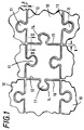
- FIG. 1 and 2 there is shown a sheet material in the form of a co-planar layer of individual plates 10 each based on a rectangle (in plan view) but having a pair of necked projections 11 formed on one opposed pair of sides 12 and 13 and having a pair of re-entrant recesses 14 formed in the other opposed pair of sides 15 and 16.
- Each plate 10 is thus similar in form to a conventional jigsaw puzzle piece of a relatively non-complex shape.
- Two side walls 12 and 15 are bevelled from the top and bottom, so as to have an edge wall profile of a V-shape, the bevels meeting on the centre plane 17 of the thickness of the plate and being formed at substantially the same angle to the planes of the top and bottom surfaces 18 and 19 of the plate.
- the other two side walls 13 and 16 are formed in a complementary manner to the side walls 12 and 15, and thus these side walls also have a V-shape, but inverted so that the top and bottom surfaces of the plate project further than the material of the plate at the centre plane of the thickness of the plate.
- An assemblage of plates as described above requires at least three different designs of plate, ignoring plates at the edge region of the sheet, all similar but differing detail insofar as the edge wall profile of one side of a given plate has to match the edge wall profile in a complementary manner of the side of the next adjacent plate with which the side of the first-mentioned plate interfits and interlocks.
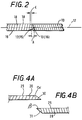
- the clearances must be very closely controlled, in order to achieve the interlocking and separation-resistance described above.
- the clearances between the profiles of two adjacent plates, respectively on a side having a necked projection and on a side having a re-entrant recess are such that the projecting V-shaped side may slide past the top or bottom surface of the next adjacent plate, interlocking will not be achieved.
- the clearance K between adjacent plates must be less than dimension A, as marked on Figure 2.
- the sheet material may display flexibility and so have the capability of being curved in at least two dimensions, there must be a minimum clearance between the plates in order to allow each plate to move slightly out of a strictly co-planar disposition, with respect to its neighbouring plates.
- the material has a nominal thickness of about 6 mm
- the length of each side of the rectangle on which each plate is based may be about 15 mm
- the projection of the centre plane on sides 12 and 15 beyond the top and bottom surfaces 18 and 19 of the plate (dimension A) is about 3 mm.
- the clearance K between the plates must be not less than 0.24 mm - but in order to give adequate security of interlocking, should be at least 50% less than dimension A.
- the material is formed as two separate sheets each consisting of a plurality of essentially identical (in plan view) plates, but with the edge walls defined by cuts extending right through the material and lying at a non-perpendicular angle to the surface of the sheet.
- the angle of cut of any one edge of a given plate in one sheet is in the opposite sense to the angle of cut of the corresponding edge of the corresponding plate in the other sheet.
- the two sheets may be manufactured either by individually forming plates and then assembling those plates together; or the plates may be formed by cuts made in a sheet of material without those plates being separated one from another, provided that the cutting can be performed with a sufficiently high degree of accuracy and with a sufficiently narrow kerf.
- a single sheet of material is cut from both sides to form the individual plates, the cutting being performed so that the two cuts meet on the centre plane of the sheet and the cutting device performing the cutting in such a way that the cut edges have the V-shaped profiles shown in Figure 2.
- Such cutting may be performed by means of a water cutting process, where an extremely fine jet of water is fired at the sheet, under a very high pressure and in a highly controlled manner, or by a laser cutting process.
- Such cutting processes are known and understood in the art and form no part of the present invention; they will not therefore be described in any detail here.
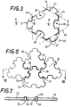
- FIGS 3 to 5 show an alternative design of sheet material utilising the principles described above with reference to Figures 1 and 2.
- each individual plate 20 is based on a hexagon and the side edges are cut in such a way that the plates are all identical and yet the material comprised by the plurality of interlocking plates displays the same characteristics as have been described above.
- FIG 3 the hexagon on which the plate is based is shown by lines 21 to 26 inclusive and it can be seen that the sides of the plate alternately have necked projections 27 and re-entrant recesses 28, of complementary forms.
- This plate profile allows adjacent plates to interlock as shown in Figure 5 and separation of the plates in the plane of the material is resisted by the projections and recesses 27 and 28 respectively interlocking. Separation in a direction normal to the plane of the material is resisted by the profile of the edges of each plate, which, on the adjacent interlocking portions, are of complementary forms.
- Figure 4A shows the profile of the edge portions of the plates on those sides which are provided with the necked projections 27 and it can be seen that these are cut with an obtuse angle ⁇ between the top face 29 and the side edge 30; on Figure 3, these edges are marked with the symbol + .
- the transitional edge regions between those indicated with + and - symbols extend essentially perpendicularly to the faces of the plate, and are marked with the symbol o .
- the clearance between adjacent plates must be sufficient to allow the material to be flexed out of a strictly co-planar configuration, but the clearance must be less than ( t/tan ⁇ ) where t is the thickness of the plate material.
- a typical embodiment of sheet material as shown in Figures 3 to 5 may consist of a polyester or epoxy resin system reinforced with aramid fibres.
- the side of the hexagon on which each plate is based may be in the range of 5 to 25 mm with the material thickness being about 6 mm.
- the plates are cut from a piece of the material without the plates being separated therefrom, for example by means of a high pressure water jet cutting technique or by laser cutting, as has been mentioned above.
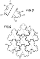
- FIG. 6 & 7 there is shown another embodiment of sheet material of this invention, constructed from a modified form of plate.
- Each of the plates 35 is generally similar to the plates 20 of the embodiment shown in Figures 3 and 4 and so will not be described again in detail here.
- the material of the plate has been cut away at 36 so that three adjoining plates together define a circular hole extending through the thickness of the material.
- a rivet 37 having an enlarged rounded head 38 on each side of the sheet material, which rivet 37 is a lose fit in the hole, as illustrated in Figure 7.
- the rivets may also be made of the same material, or could be made from hardened steel.
- Figure 8 shows two separate plate-parts 40 and 41 which are manufactured separately but which may be joined together by a fusion technique so as to form a complete plate similar to that shown in Figure 3.
- Such plate-parts may be manufactured by machining, casting or forging techniques from suitable materials, so as to have appropriate edge profiles, as has been described above with reference to Figures 3 and 4.
- a plurality of the plate-parts may be assembled together as shown in Figure 8 and the two plate-parts of each plate are then welded or otherwise fused together along lines 42, for example by a laser welding technique, so as to form a complete, flexible sheet material of this invention. Provided that the welding is properly performed, the finished sheet material displays essentially the same characteristics as the material of Figure 5, consisting of plates 20 ( Figure 3).
Landscapes
- Engineering & Computer Science (AREA)
- General Engineering & Computer Science (AREA)
- Textile Engineering (AREA)
- Laminated Bodies (AREA)
- Materials For Medical Uses (AREA)
- Finishing Walls (AREA)
- Building Environments (AREA)
- Professional, Industrial, Or Sporting Protective Garments (AREA)
Claims (13)
- Flexibles, durchdringungsfestes Flächenmaterial, welches eine Mehrzahl von starren, nahe nebeneinander angeordneten, gesonderten Platten (10) aufweist, welche alle im wesentlichen in derselben Ebene liegen, wenn das Material eben ausgelegt ist, wobei die Randwände (31, 31) jeder Platte mit jener einer benachbarten Platte zusammenarbeiten, dadurch gekennzeichnet, daß das Flächenmaterial eine einzige Schicht umfaßt, und daß die Randwände (30) jeder Platte ineinander passend und gegenseitig festgelegt mit und zu den Randwänden (31) der jeweils benachbarten Platten angeordnet sind, um einer relativen Trennung der Platten in einer Richtung senkrecht zu der Ebene (17) des Materials einen Widerstand entgegenzusetzen.
- Flexibles Material nach Anspruch 1, bei dem ein Teil der Länge der Randwand einer Platte ein konvexes Profil hat, und der Teil der Randwand einer benachbarten Platte, welcher mit dieser ineinander paßt und eine gegenseitige Festlegung bewirkt, ein Randwandprofil mit einer komplementären, konkaven Gestalt hat.
- Flexibles Material nach Anspruch 1, bei dem die Länge der Randwand einer Platte ein Profil hat, welches von einer Abschrägung gebildet wird, um eine im allgemeinen V-förmige Gestalt (12) zu bekommen, und bei dem der Teil des Umfangs der benachbarten Platte, welche hiermit ineinander passend und gegenseitig festlegend zusammenarbeitet, ein Randwandprofil mit einer komplementären, gestürzten V-förmigen Gestalt (13) hat.
- Flexibles Material nach Anspruch 1, bei dem ein Teil der Länge der Randwand einer Platte ein Profil (30) hat, welches unter einem spitzen Winkel zu einer Fläche der Platte liegt, und ein weiterer Teil der Länge der Randwand ein Profil (29) mit einem stumpfen Winkel zu einer Fläche der Platte hat, wobei die Randwandteile an den Umfängen von benachbarten Platten, welche ineinander passend und gegenseitig festlegend zusammenarbeiten, zugeordnete Randwandprofilteile in komplementärer Ausgestaltungsform haben.
- Flexibles Material nach Anspruch 4, bei dem die Randwände irgendeiner Platte aufeinanderfolgende Randwandteile haben, welche abwechselnd in jeweils spitzen und stumpfen Winkeln angeordnet sind.
- Flexibles Material nach Anspruch 4 oder Anspruch 5, bei dem jede Platte wenigstens eine Symmetrieebene senkrecht zur Oberfläche der Platte hat.
- Flexibles Material nach Anspruch 6, bei dem jede Platte in der Ebene die gleiche Gestalt wie alle anderen Platten haben.
- Flexibles Material nach einem der vorangehenden Ansprüche, bei dem jede Platte auf einem Polygon mit einer geraden Anzahl von Seiten basiert, die Seiten wechselweise einen eingezogenen Vorsprung (27) und eine einspringende Ausnehmung (28) mit komplementärer Ausgestaltung haben, die Platten gegenüber einer relativen Bewegung in ihrer gemeinsamen Ebene (17) durch die Vorsprünge einer Platte festgelegt sind, welche in zugeordneten Ausnehmungen benachbarter Platten aufgenommen sind, und bei dem eine Platte in den Ausnehmungen die Vorsprünge benachbarter Platten aufnimmt.
- Flexibles Material nach Anspruch 8, bei dem jede Platte auf einem Sechseck basiert.
- Flexibles Material nach einem der vorangehenden Ansprüche, bei dem jede Platte aus einem Material hergestellt ist, welches aus der Gruppe ausgewählt ist, welche folgendes umfaßt: Titan, Aluminium, Stahl, keramischen Werkstoff, aushärtbares Material thermoplastisches Material, Holz, Schichtholz und Zusammensetzungen von Fasermaterialien und einem Harzsystem.
- Flexibles Material nach einem der vorangehenden Ansprüche, bei dem der Bereich der Verbindung zwischen drei oder mehr Platten mit einer Öffnung (36) versehen ist, und ein loser Stopfen (37) in die Öffnung passend einsetzbar ist.
- Verfahren zum Herstellen eines flexiblen Materials nach einem der vorangehenden Ansprüche, welches den Schritt umfaßt, gemäß dem ein starres Flächenmaterial zur Bildung der ineinander passend und gegenseitig festlegbaren Platten zum gegenseitigen Festlegen dieser Platten zugeschnitten wird, ohne daß die einzelnen Platten voneinander gelöst sind.
- Verfahren nach Anspruch 11, bei dem das Flächengebilde mittels einer Wasserstrahl- oder Laser-Schneideinrichtung zugeschnitten wird.
Applications Claiming Priority (3)
| Application Number | Priority Date | Filing Date | Title |
|---|---|---|---|
| GB939309486A GB9309486D0 (en) | 1993-05-05 | 1993-05-05 | Flexible sheet material |
| GB9309486 | 1993-05-05 | ||
| PCT/GB1994/000472 WO1994024894A1 (en) | 1993-05-05 | 1994-03-10 | Flexible sheet material |
Publications (2)
| Publication Number | Publication Date |
|---|---|
| EP0697824A1 EP0697824A1 (de) | 1996-02-28 |
| EP0697824B1 true EP0697824B1 (de) | 1997-10-01 |
Family
ID=10735137
Family Applications (1)
| Application Number | Title | Priority Date | Filing Date |
|---|---|---|---|
| EP94909178A Expired - Lifetime EP0697824B1 (de) | 1993-05-05 | 1994-03-10 | Flexibles dünnes material |
Country Status (8)
| Country | Link |
|---|---|
| EP (1) | EP0697824B1 (de) |
| JP (1) | JPH08511861A (de) |
| AT (1) | ATE158697T1 (de) |
| AU (1) | AU6211794A (de) |
| DE (1) | DE69405988D1 (de) |
| GB (1) | GB9309486D0 (de) |
| WO (1) | WO1994024894A1 (de) |
| ZA (1) | ZA943096B (de) |
Cited By (1)
| Publication number | Priority date | Publication date | Assignee | Title |
|---|---|---|---|---|
| AU2009208585B2 (en) * | 2008-01-28 | 2013-09-19 | Rafael Advanced Defense Systems Ltd. | Protective divide and method for protection |
Families Citing this family (14)
| Publication number | Priority date | Publication date | Assignee | Title |
|---|---|---|---|---|
| DE19819737C2 (de) * | 1998-05-04 | 2000-02-17 | Ziegler Mechanische Werkstatt Metallgewebe & Arbeitsschutz Gmbh | Gewebe, insbesondere Stichschutzgewebe |
| GB0024896D0 (en) | 2000-10-11 | 2000-11-22 | Secr Defence | Eye protection devices |
| GB2368383A (en) * | 2000-10-26 | 2002-05-01 | Secr Defence | An armour tile with angled edges |
| FI7368U1 (fi) * | 2006-10-04 | 2007-01-18 | Cpe Production Oy | Suojaliivi |
| US7963204B2 (en) | 2007-07-24 | 2011-06-21 | Oshkosh Corporation | Stressed skin tiled vehicle armor |
| US9322621B2 (en) | 2009-10-27 | 2016-04-26 | Edan Administration Services (Ireland) Limited | Armor system |
| US8402876B2 (en) | 2009-10-27 | 2013-03-26 | Edan Administration Services (Ireland) Limited | Ballistic lightweight ceramic armor with cross-pellets |
| US9709363B2 (en) | 2012-09-23 | 2017-07-18 | Edan Administration Services (Ireland) Limited | Armor system |
| WO2015193735A1 (en) * | 2014-06-19 | 2015-12-23 | Revision Military S.À.R.L. | Wearable armor plate assembly |
| CN104501659B (zh) * | 2014-12-01 | 2017-08-15 | 上海圣甲安全防护科技有限公司 | 用于制作柔性防刺材料的复合材料及防刺材料的制备方法 |
| CN109737817A (zh) * | 2019-02-11 | 2019-05-10 | 东华大学 | 一种倾斜式柔性防刺材料及其制备方法 |
| CN110057246B (zh) * | 2019-05-06 | 2024-05-07 | 苏州高甲防护科技有限公司 | 一种插槽式高安全性的防刺面料结构 |
| CN113237387B (zh) * | 2021-05-10 | 2022-08-05 | 哈尔滨工业大学 | 一种包含互锁结构的抗弹铝基复合材料及其制备方法 |
| IT202200007115A1 (it) * | 2022-04-11 | 2023-10-11 | Ind Bitossi S P A | Struttura di protezione antiproiettile |
Family Cites Families (5)
| Publication number | Priority date | Publication date | Assignee | Title |
|---|---|---|---|---|
| US3867239A (en) * | 1973-06-11 | 1975-02-18 | Us Army | Body armor construction |
| DE2741180C2 (de) * | 1977-09-13 | 1984-09-27 | Ebro Elektrotechnische Fabrik, 8070 Ingolstadt | Weiche Schutzkonstruktion für den Körperschutz |
| US4483020A (en) * | 1982-11-17 | 1984-11-20 | Jack P. Cittadine | Projectile proof vest |
| JPH0650240B2 (ja) * | 1985-08-16 | 1994-06-29 | 伊藤忠商事株式会社 | 人体防護材 |
| GB9105233D0 (en) * | 1991-03-12 | 1991-04-24 | Bryant Lionel | Flexible body armour |
-
1993
- 1993-05-05 GB GB939309486A patent/GB9309486D0/en active Pending
-
1994
- 1994-03-10 WO PCT/GB1994/000472 patent/WO1994024894A1/en not_active Ceased
- 1994-03-10 EP EP94909178A patent/EP0697824B1/de not_active Expired - Lifetime
- 1994-03-10 DE DE69405988T patent/DE69405988D1/de not_active Expired - Lifetime
- 1994-03-10 AU AU62117/94A patent/AU6211794A/en not_active Abandoned
- 1994-03-10 JP JP6523984A patent/JPH08511861A/ja active Pending
- 1994-03-10 AT AT94909178T patent/ATE158697T1/de active
- 1994-05-05 ZA ZA943096A patent/ZA943096B/xx unknown
Cited By (1)
| Publication number | Priority date | Publication date | Assignee | Title |
|---|---|---|---|---|
| AU2009208585B2 (en) * | 2008-01-28 | 2013-09-19 | Rafael Advanced Defense Systems Ltd. | Protective divide and method for protection |
Also Published As
| Publication number | Publication date |
|---|---|
| JPH08511861A (ja) | 1996-12-10 |
| EP0697824A1 (de) | 1996-02-28 |
| ZA943096B (en) | 1995-01-26 |
| AU6211794A (en) | 1994-11-21 |
| ATE158697T1 (de) | 1997-10-15 |
| DE69405988D1 (de) | 1997-11-06 |
| WO1994024894A1 (en) | 1994-11-10 |
| GB9309486D0 (en) | 1993-06-23 |
Similar Documents
| Publication | Publication Date | Title |
|---|---|---|
| EP0697824B1 (de) | Flexibles dünnes material | |
| WO1993021492A1 (en) | Armour tiles and flexible armour composed of such tiles | |
| SU852182A3 (ru) | М гка защитна конструкци | |
| US4760611A (en) | Armor elements and method | |
| JPH0650240B2 (ja) | 人体防護材 | |
| US7318764B2 (en) | 3-dimensional assembly | |
| US4757742A (en) | Composite ballistic armor system | |
| US5842697A (en) | Polyhedral surface jigsaw puzzles | |
| WO2007149242A2 (en) | Indexable cutting insert with multiple cutting edges | |
| WO2001021518A8 (en) | Safe cut-off blade assembly | |
| US7698984B2 (en) | Ballistic projectile resistant barrier apparatus | |
| EP3706879B1 (de) | Bauelement für unterschiedliche verwendungen | |
| SE8400949L (sv) | Slepborrspets och skerelement | |
| KR20000049257A (ko) | 밀링용 공구 및 절삭 삽입체 | |
| EP0160400A2 (de) | Jigsaw-Puzzle | |
| TW201217087A (en) | Double-sided cutting inserts for hign feed milling | |
| AU2009208585B2 (en) | Protective divide and method for protection | |
| EP0851964A1 (de) | Schneideinsatz für eine bohrlochfräse | |
| US4705434A (en) | Scalloped polygonal cutting insert | |
| US6601849B1 (en) | Golf ball spherical puzzle | |
| GB2283902A (en) | Armour, e.g. for jackets | |
| EP1562494B1 (de) | Einwegskalpell mit einziehbarer klinge | |
| US5205556A (en) | Geodesic globe puzzle | |
| GB2368383A (en) | An armour tile with angled edges | |
| GB2303534A (en) | Body armour |
Legal Events
| Date | Code | Title | Description |
|---|---|---|---|
| PUAI | Public reference made under article 153(3) epc to a published international application that has entered the european phase |
Free format text: ORIGINAL CODE: 0009012 |
|
| 17P | Request for examination filed |
Effective date: 19951106 |
|
| AK | Designated contracting states |
Kind code of ref document: A1 Designated state(s): AT CH DE DK ES FR GB IT LI NL SE |
|
| GRAG | Despatch of communication of intention to grant |
Free format text: ORIGINAL CODE: EPIDOS AGRA |
|
| RIN1 | Information on inventor provided before grant (corrected) |
Inventor name: PATCHETT, KIM |
|
| RAP1 | Party data changed (applicant data changed or rights of an application transferred) |
Owner name: WALLACE, STUART IAN Owner name: PATCHETT, KIM |
|
| 17Q | First examination report despatched |
Effective date: 19961209 |
|
| GRAH | Despatch of communication of intention to grant a patent |
Free format text: ORIGINAL CODE: EPIDOS IGRA |
|
| GRAH | Despatch of communication of intention to grant a patent |
Free format text: ORIGINAL CODE: EPIDOS IGRA |
|
| GRAA | (expected) grant |
Free format text: ORIGINAL CODE: 0009210 |
|
| AK | Designated contracting states |
Kind code of ref document: B1 Designated state(s): AT CH DE DK ES FR GB IT LI NL SE |
|
| PG25 | Lapsed in a contracting state [announced via postgrant information from national office to epo] |
Ref country code: NL Free format text: LAPSE BECAUSE OF FAILURE TO SUBMIT A TRANSLATION OF THE DESCRIPTION OR TO PAY THE FEE WITHIN THE PRESCRIBED TIME-LIMIT Effective date: 19971001 Ref country code: LI Effective date: 19971001 Ref country code: IT Free format text: LAPSE BECAUSE OF FAILURE TO SUBMIT A TRANSLATION OF THE DESCRIPTION OR TO PAY THE FEE WITHIN THE PRE;WARNING: LAPSES OF ITALIAN PATENTS WITH EFFECTIVE DATE BEFORE 2007 MAY HAVE OCCURRED AT ANY TIME BEFORE 2007. THE CORRECT EFFECTIVE DATE MAY BE DIFFERENT FROM THE ONE RECORDED.SCRIBED TIME-LIMIT Effective date: 19971001 Ref country code: FR Free format text: LAPSE BECAUSE OF FAILURE TO SUBMIT A TRANSLATION OF THE DESCRIPTION OR TO PAY THE FEE WITHIN THE PRESCRIBED TIME-LIMIT Effective date: 19971001 Ref country code: ES Free format text: THE PATENT HAS BEEN ANNULLED BY A DECISION OF A NATIONAL AUTHORITY Effective date: 19971001 Ref country code: DK Free format text: LAPSE BECAUSE OF NON-PAYMENT OF DUE FEES Effective date: 19971001 Ref country code: CH Effective date: 19971001 Ref country code: AT Free format text: LAPSE BECAUSE OF FAILURE TO SUBMIT A TRANSLATION OF THE DESCRIPTION OR TO PAY THE FEE WITHIN THE PRESCRIBED TIME-LIMIT Effective date: 19971001 |
|
| REF | Corresponds to: |
Ref document number: 158697 Country of ref document: AT Date of ref document: 19971015 Kind code of ref document: T |
|
| REG | Reference to a national code |
Ref country code: CH Ref legal event code: EP |
|
| REF | Corresponds to: |
Ref document number: 69405988 Country of ref document: DE Date of ref document: 19971106 |
|
| PG25 | Lapsed in a contracting state [announced via postgrant information from national office to epo] |
Ref country code: SE Effective date: 19980101 |
|
| PG25 | Lapsed in a contracting state [announced via postgrant information from national office to epo] |
Ref country code: DE Free format text: LAPSE BECAUSE OF FAILURE TO SUBMIT A TRANSLATION OF THE DESCRIPTION OR TO PAY THE FEE WITHIN THE PRESCRIBED TIME-LIMIT Effective date: 19980103 |
|
| EN | Fr: translation not filed | ||
| NLV1 | Nl: lapsed or annulled due to failure to fulfill the requirements of art. 29p and 29m of the patents act | ||
| PG25 | Lapsed in a contracting state [announced via postgrant information from national office to epo] |
Ref country code: GB Free format text: LAPSE BECAUSE OF NON-PAYMENT OF DUE FEES Effective date: 19980310 |
|
| REG | Reference to a national code |
Ref country code: CH Ref legal event code: PL |
|
| PLBE | No opposition filed within time limit |
Free format text: ORIGINAL CODE: 0009261 |
|
| STAA | Information on the status of an ep patent application or granted ep patent |
Free format text: STATUS: NO OPPOSITION FILED WITHIN TIME LIMIT |
|
| 26N | No opposition filed | ||
| GBPC | Gb: european patent ceased through non-payment of renewal fee |
Effective date: 19980310 |