EP0697349A1 - Device for metered dispensing of flowable product - Google Patents
Device for metered dispensing of flowable product Download PDFInfo
- Publication number
- EP0697349A1 EP0697349A1 EP95111284A EP95111284A EP0697349A1 EP 0697349 A1 EP0697349 A1 EP 0697349A1 EP 95111284 A EP95111284 A EP 95111284A EP 95111284 A EP95111284 A EP 95111284A EP 0697349 A1 EP0697349 A1 EP 0697349A1
- Authority
- EP
- European Patent Office
- Prior art keywords
- annular
- actuating element
- container
- closing flap
- delivery tube
- Prior art date
- Legal status (The legal status is an assumption and is not a legal conclusion. Google has not performed a legal analysis and makes no representation as to the accuracy of the status listed.)
- Withdrawn
Links
Images
Classifications
-
- B—PERFORMING OPERATIONS; TRANSPORTING
- B65—CONVEYING; PACKING; STORING; HANDLING THIN OR FILAMENTARY MATERIAL
- B65D—CONTAINERS FOR STORAGE OR TRANSPORT OF ARTICLES OR MATERIALS, e.g. BAGS, BARRELS, BOTTLES, BOXES, CANS, CARTONS, CRATES, DRUMS, JARS, TANKS, HOPPERS, FORWARDING CONTAINERS; ACCESSORIES, CLOSURES, OR FITTINGS THEREFOR; PACKAGING ELEMENTS; PACKAGES
- B65D83/00—Containers or packages with special means for dispensing contents
- B65D83/14—Containers or packages with special means for dispensing contents for delivery of liquid or semi-liquid contents by internal gaseous pressure, i.e. aerosol containers comprising propellant for a product delivered by a propellant
- B65D83/44—Valves specially adapted therefor; Regulating devices
-
- B—PERFORMING OPERATIONS; TRANSPORTING
- B65—CONVEYING; PACKING; STORING; HANDLING THIN OR FILAMENTARY MATERIAL
- B65D—CONTAINERS FOR STORAGE OR TRANSPORT OF ARTICLES OR MATERIALS, e.g. BAGS, BARRELS, BOTTLES, BOXES, CANS, CARTONS, CRATES, DRUMS, JARS, TANKS, HOPPERS, FORWARDING CONTAINERS; ACCESSORIES, CLOSURES, OR FITTINGS THEREFOR; PACKAGING ELEMENTS; PACKAGES
- B65D83/00—Containers or packages with special means for dispensing contents
- B65D83/14—Containers or packages with special means for dispensing contents for delivery of liquid or semi-liquid contents by internal gaseous pressure, i.e. aerosol containers comprising propellant for a product delivered by a propellant
- B65D83/16—Containers or packages with special means for dispensing contents for delivery of liquid or semi-liquid contents by internal gaseous pressure, i.e. aerosol containers comprising propellant for a product delivered by a propellant characterised by the actuating means
- B65D83/20—Containers or packages with special means for dispensing contents for delivery of liquid or semi-liquid contents by internal gaseous pressure, i.e. aerosol containers comprising propellant for a product delivered by a propellant characterised by the actuating means operated by manual action, e.g. button-type actuator or actuator caps
- B65D83/205—Actuator caps, or peripheral actuator skirts, attachable to the aerosol container
-
- B—PERFORMING OPERATIONS; TRANSPORTING
- B65—CONVEYING; PACKING; STORING; HANDLING THIN OR FILAMENTARY MATERIAL
- B65D—CONTAINERS FOR STORAGE OR TRANSPORT OF ARTICLES OR MATERIALS, e.g. BAGS, BARRELS, BOTTLES, BOXES, CANS, CARTONS, CRATES, DRUMS, JARS, TANKS, HOPPERS, FORWARDING CONTAINERS; ACCESSORIES, CLOSURES, OR FITTINGS THEREFOR; PACKAGING ELEMENTS; PACKAGES
- B65D83/00—Containers or packages with special means for dispensing contents
- B65D83/14—Containers or packages with special means for dispensing contents for delivery of liquid or semi-liquid contents by internal gaseous pressure, i.e. aerosol containers comprising propellant for a product delivered by a propellant
- B65D83/75—Aerosol containers not provided for in groups B65D83/16 - B65D83/74
- B65D83/753—Aerosol containers not provided for in groups B65D83/16 - B65D83/74 characterised by details or accessories associated with outlets
- B65D83/7535—Outlet valves opened by the product to be delivered
Definitions
- the invention relates to a device for the metered discharge of a flowable medium, in particular a pasty mass, such as cream, gel or the like, consisting of a container with a dispensing valve, which is movable against the action of an elastic element into the container interior and / or around it Includes longitudinally tiltable dispensing tube.
- a flowable medium in particular a pasty mass, such as cream, gel or the like
- a dispensing valve which is movable against the action of an elastic element into the container interior and / or around it Includes longitudinally tiltable dispensing tube.
- Such devices are generally known. They each have a container with a container opening that can be closed by a lid.
- the lid also has an opening to which a dispensing valve can be attached. This construction is particularly known in connection with so-called aerosol cans.
- the delivery tube can be coupled to an actuating element having an annular channel in such a way that the annular channel is fluidly connected to the delivery tube, the annular channel being closed by an annular closing flap which, when opened under pressure, defines an annular gap opening for the exit of the medium.
- This construction allows a convenient and residue-free stripping of the emerging medium from the annular gap opening with the user's finger. Beyond that ensures that in the closed position of the device or of the dispensing valve, the medium located in the actuating element is hermetically sealed from the surroundings by the annular closing flap. Accordingly, there is no premature oxidation of the medium that accumulates in the actuating element after the device has been used for the first time. This applies in particular if the annular closing flap is prestressed in the closing direction.
- a device for the metered discharge of a flowable medium in particular a cream, a gel or the like, is shown in a partial sectional view, this device having a can-like container 10, the upper opening of which is closed with a lid 11 in a fluid-tight manner is.
- an O-ring seal 12 is arranged between the upper edge of the container opening and the edge of the lid.
- An opening is also provided in the cover 11, at the edge of which a dispensing valve is fastened in a fluid-tight manner.
- This dispensing valve comprises a dispensing tube 14 which can be moved into the interior of the container and / or can be tilted about its longitudinal axis 13 counter to the action of an elastic element, in particular a helical compression spring.
- the dispensing tube 14 protrudes outward through the lid 11.
- This valve construction is generally known, especially in connection with so-called aerosol cans, so that a more detailed description of this construction is unnecessary here.
- the dispensing tube 14 can be coupled to an actuating element in the form of an actuating button 15.
- a pot-like receptacle 16 for the outlet end 17 of the delivery tube 14 is formed, namely molded, on the inside of the actuation button 15 facing the delivery tube 14, namely in such a way that it closely encloses the outlet end 17 of the delivery tube 14 and is accordingly fluid-tight.
- the interior 18 of the pot-like receptacle 16 is fluidly connected to an annular channel 19 formed on the outside, ie the side of the actuation button 15 facing away from the container 10.
- a corresponding ring-shaped closing flap 20 is assigned to the annular channel 19 and defines an annular gap opening 21 for the outlet of the medium when the dispensing valve is opened under the pressure of the container contents.
- the exit of the medium through the gap opening 21 is shown in FIG. 2 with the arrows 22.
- the central region 23 delimited by the annular closing flap 20 and the annular closing flap 20 itself define a continuously smooth surface.
- the closing flap is flush with the central area 23 in the closed position.
- the annular closing flap 20 is preferably pretensioned in the closed position, in order in this way to ensure hermetic sealing of the medium located in the interior 18 and annular channel 19 from the external environment when the device is not in use.
- the annular closing flap 19 and the central region 23 define a flat or flat surface. Instead, this surface can also be either slightly convex or slightly concave.
- the actuation button 15 is part of a container cap 24. It is integral with its one end 25 with the container cap 24 and with its other, diametrical end 26 relative to the dispensing tube 14 or annular closing flap 20, via a predetermined breaking point in the form of predetermined breaking bars 27 with the Container cap connected.
- the annular locking tab 20 is part of a separate component 28 which can be fastened to the actuation button 15 in association with the ring channel 19.
- a groove 29 is formed on the outside of the actuation button 15 and extends around the ring channel 19, into which a complementary ring web 30 can be inserted on the component 28 having the locking tab 20, with a press fit.
- the container cap 24 comprising the actuation button 15 can be clipped onto the peripheral edge 31 of the cylindrical container 10 while simultaneously capturing the delivery tube 14 through the pot-like receptacle 16 on the side of the actuation button 15 facing the inside or the container 10.
- the inner or the delivery tube 14 facing peripheral edge 32 of the pot-like receptacle 16 for the dispensing tube 14 or its outlet end 17 is expanded conically or trumpet-like radially outward. This measure makes it easier to assemble the container cap 24 in association with the dispensing tube 14.
- the actuation button 15 also has a push button in the form of a dent-like depression 33 at the end 26 on the breakage side.
Abstract
Description
Die Erfindung betrifft eine Vorrichtung zum dosierten Austrag eines fließfähigen Mediums, insbesondere einer pastösen Masse, wie Creme, Gel oder dergleichen, bestehend aus einem Behälter mit einem Abgabeventil, welches ein entgegen der Wirkung eines elastischen Elements in das Behälterinnere hinein bewegbares und/oder um seine Längsachse kippbares Abgaberöhrchen umfaßt.The invention relates to a device for the metered discharge of a flowable medium, in particular a pasty mass, such as cream, gel or the like, consisting of a container with a dispensing valve, which is movable against the action of an elastic element into the container interior and / or around it Includes longitudinally tiltable dispensing tube.
Derartige Vorrichtungen sind allgemein bekannt. Sie weisen jeweils einen Behälter mit einer Behälteröffnung auf, die durch einen Deckel verschließbar ist. Der Deckel weist ebenfalls eine Öffnung auf, an der ein Abgabeventil befestigbar ist. Diese Konstruktion ist insbesondere in Verbindung mit sogenannten Aerosol-Dosen bekannt.Such devices are generally known. They each have a container with a container opening that can be closed by a lid. The lid also has an opening to which a dispensing valve can be attached. This construction is particularly known in connection with so-called aerosol cans.
Im vorliegenden Fall geht es um die vorteilhafte Ausbildung eines Betätigungselements für das Abgaberöhrchen, wobei das Betätigungselement zugleich einen für das Abstreichen der pastösen Masse vorteilhaften Austragsmechanismus aufweisen soll.In the present case, it is a question of the advantageous design of an actuating element for the dispensing tube, the actuating element at the same time being intended to have a discharge mechanism which is advantageous for wiping off the pasty mass.
Dieses Ziel wird durch die kennzeichnenden Merkmale des Anspruches 1 gelöst. Dementsprechend ist das Abgaberöhrchen mit einem einen ringförmigen Kanal aufweisenden Betätigungselement koppelbar derart, daß der ringförmige Kanal mit dem Abgaberöhrchen fluidverbunden ist, wobei der ringförmige Kanal durch einen ringförmigen Schließlappen verschlossen ist, der bei Öffnung unter Druck eine ringförmige Spaltöffnung zum Austritt des Mediums definiert. Diese Konstruktion erlaubt ein bequemes und rückstandsfreies Abstreifen des austretenden Mediums von der ringförmigen Spaltöffnung mit dem Finger des Benutzers. Darüber hinaus ist gewährleistet, daß in Schließstellung der Vorrichtung bzw. des Abgabeventils im Betätigungselement befindliches Medium durch den ringförmigen Schließlappen gegenüber der Umgebung hermetisch abgedichtet ist. Dementsprechend erfolgt keine vorzeitige Oxidation des sich nach erstmaligem Gebrauch der Vorrichtung im Betätigungselement ansammelnden Mediums. Dies gilt insbesondere dann, wenn der ringförmige Schließlappen entsprechend Anspruch 9 in Schließrichtung vorgespannt ist.This object is achieved by the characterizing features of claim 1. Accordingly, the delivery tube can be coupled to an actuating element having an annular channel in such a way that the annular channel is fluidly connected to the delivery tube, the annular channel being closed by an annular closing flap which, when opened under pressure, defines an annular gap opening for the exit of the medium. This construction allows a convenient and residue-free stripping of the emerging medium from the annular gap opening with the user's finger. Beyond that ensures that in the closed position of the device or of the dispensing valve, the medium located in the actuating element is hermetically sealed from the surroundings by the annular closing flap. Accordingly, there is no premature oxidation of the medium that accumulates in the actuating element after the device has been used for the first time. This applies in particular if the annular closing flap is prestressed in the closing direction.
Weitere konstruktive Details der erfindungsgemäßen Vorrichtung sind in den Unteransprüchen beschrieben.Further structural details of the device according to the invention are described in the subclaims.
Nachstehend wird eine Ausführungsform der erfindungsgemäßen Vorrichtung anhand der beigefügten Zeichnung näher erläutert. Es zeigen:
- Fig. 1
- eine erfindungsgemäß ausgebildete Vorrichtung teilweise im Längsschnitt, teilweise in Seitenansicht, und zwar in Schließstellung des Abgabeventils; und
- Fig. 2
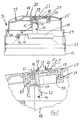
- einen Teil der Vorrichtung gem. Fig. 1 im Längsschnitt und vergrößertem Maßstab, und zwar bei Offenstellung des Abgabeventils.
- Fig. 1
- an inventive device partially in longitudinal section, partially in side view, in the closed position of the dispensing valve; and
- Fig. 2
- part of the device acc. Fig. 1 in longitudinal section and on an enlarged scale, with the dispensing valve open.
In Fig. 1 ist der obere Teil einer Vorrichtung zum dosierten Austrag eines fließfähigen Mediums, insbesondere einer Creme, eines Gels oder dergleichen, in Teilschnitt-Ansicht dargestellt, wobei diese Vorrichtung einen dosenartigen Behälter 10 aufweist, dessen obere Öffnung mit einem Deckel 11 fluiddicht verschlossen ist. Zu diesem Zweck ist zwischen dem oberen Rand der Behälteröffnung und dem Deckelrand eine O-Ringdichtung 12 angeordnet. Im Deckel 11 ist ebenfalls eine Öffnung vorgesehen, an deren Rand ein Abgabeventil fluiddicht befestigt ist. Dieses Abgabeventil umfaßt ein entgegen der Wirkung eines elastischen Elements, insbesondere einer Schraubendruckfeder, in das Behälterinnere hineinbewegbares und/oder um seine Längsachse 13 kippbares Abgaberöhrchen 14.In Fig. 1 the upper part of a device for the metered discharge of a flowable medium, in particular a cream, a gel or the like, is shown in a partial sectional view, this device having a can-
Das Abgaberöhrchen 14 steht über den Deckel 11 nach außen vor. Diese Ventilkonstruktion ist allgemein bekannt, insbesondere in Verbindung mit sogenannten Aerosol-Dosen, so daß sich hier eine nähere Beschreibung dieser Konstruktion erübrigt.The dispensing
Das Abgaberöhrchen 14 ist mit einem Betätigungselement in Form einer Betätigungstaste 15 koppelbar. Zu diesem Zweck ist an der dem Abgaberöhrchen 14 zugewandten Innenseite der Betätigungstaste 15 eine topfartige Aufnahme 16 für das Austrittsende 17 des Abgaberöhrchens 14 ausgebildet, nämlich angeformt, und zwar derart, daß sie das Austrittsende 17 des Abgaberöhrchens 14 eng und dementsprechend fluiddicht umschließt. Der Innenraum 18 der topfartigen Aufnahme 16 ist mit einem an der Außenseite, d. h. dem Behälter 10 abgewandten Seite der Betätigungstaste 15 ausgebildeten Ringkanal 19 fluidverbunden. Dem ringförmigen Kanal 19 ist ein entsprechend ringförmiger Schließlappen 20 zugeordnet, der bei Öffnung des Abgabeventils unter dem Druck des Behälterinhalts eine ringförmige Spaltöffnung 21 zum Austritt des Mediums definiert. Der Austritt des Mediums durch die Spaltöffnung 21 ist in Fig. 2 mit den Pfeilen 22 dargestellt. In Schließstellung definiert der vom ringförmigen Schließlappen 20 begrenzte Zentralbereich 23 sowie der ringförmige Schließlappen 20 selbst eine durchgehend glatte Oberfläche. Der Schließlappen grenzt in Schließstellung bündig am Zentralbereich 23 an. Vorzugsweise ist der ringförmige Schließlappen 20 in Schließstellung vorgespannt, um auf diese Weise bei Nichtbenutzung der Vorrichtung eine hermetische Abdichtung des sich im Innenraum 18 und Ringkanal 19 befindlichen Mediums gegenüber der äußeren Umgebung sicherzustellen. Bei der dargestellten Ausführungsform definiert der ringförmige Schließlappen 19 sowie der Zentralbereich 23 eine flache bzw. ebene Fläche. Diese Fläche kann statt dessen auch entweder geringfügig konvex oder geringfügig konkav gewölbt sein.The
Die Betätigungstaste 15 ist Teil einer Behälterkappe 24. Sie ist mit ihrem einen Ende 25 integral mit der Behälterkappe 24 und mit ihrem anderen, relativ zum Abgaberöhrchen 14 bzw. ringförmigen Schließlappen 20 diametralen Ende 26 über eine Garantie-Sollbruchstelle in Form von Sollbruchstegen 27 mit der Behälterkappe verbunden.The
Der ringförmige Schließlappen 20 ist Teil eines gesonderten Bauelements 28, welches an der Betätigungstaste 15 in Zuordnung zum Ringkanal 19 befestigbar ist. Zu diesem Zweck ist an der Außenseite der Betätigungstaste 15 eine sich um den Ringkanal 19 herum erstreckende Nut 29 ausgebildet, in die ein komplementärer Ringsteg 30 an dem den Schließlappen 20 aufweisenden Bauelement 28 einsteckbar ist, und zwar mit Preßsitz.The
Die die Betätigungstaste 15 umfassende Behälterkappe 24 ist auf den Umfangsrand 31 des zylindrischen Behälters 10 klemmend aufsteckbar unter gleichzeitiger Erfassung des Abgaberöhrchens 14 durch die topfartige Aufnahme 16 an der Innen- bzw. dem Behälter 10 zugewandten Seite der Betätigungstaste 15. Der innere bzw. dem Abgaberöhrchen 14 zugewandte Umfangsrand 32 der topfartigen Aufnahme 16 für das Abgaberöhrchen 14 bzw. dessen Austrittsende 17 ist radial nach außen konisch bzw. trompetenartig erweitert. Durch diese Maßnahme wird die Montage der Behälterkappe 24 in Zuordnung zum Abgaberöhrchen 14 erleichtert.The
Die Betätigungstaste 15 weist am sollbruchseitigen Ende 26 noch eine Drucktaste in Form einer dellenartigen Vertiefung 33 auf.The
Sämtliche in den Anmeldungsunterlagen offenbarten Merkmale werden als erfindungswesentlich beansprucht, soweit sie einzeln oder in Kombination gegenüber dem Stand der Technik neu sind.All features disclosed in the application documents are claimed as essential to the invention, insofar as they are new compared to the prior art, individually or in combination.
- 1010th
- Behältercontainer
- 1111
- Deckelcover
- 1212th
- O-RingdichtungO-ring seal
- 1313
- Längsachse des AbgaberöhrchensLongitudinal axis of the delivery tube
- 1414
- AbgaberöhrchenDispensing tubes
- 1515
- Betätigungselement bzw. -tasteActuator or button
- 1616
- topfartige Aufnahmepot-like intake
- 1717th
- Austrittsende des AbgaberöhrchensExit end of the delivery tube
- 1818th
- Innenraum der topfartigen AufnahmeInterior of the pot-like receptacle
- 1919th
- RingkanalRing channel
- 2020th
- SchließlappenClosing flap
- 2121
- RingspaltöffnungAnnular gap opening
- 2222
- Pfeilarrow
- 2323
- ZentralbereichCentral area
- 2424th
- BehälterkappeContainer cap
- 2525th
- das eine Ende der Betätigungstasteone end of the operation button
- 2626
- das andere Ende der Betätigungstastethe other end of the operation button
- 2727
- SollbruchstegPredetermined breaking web
- 2828
- BauelementComponent
- 2929
- RingnutRing groove
- 3030th
- RingstegRing bridge
- 3131
- UmfangsrandPeripheral edge
- 3232
- UmfangsrandPeripheral edge
- 3333
- dellenartige Vertiefungdent-like depression
Claims (12)
dadurch gekennzeichnet,
daß das Abgaberöhrchen (14) mit einem einen ringförmigen Kanal (19) aufweisenden Betätigungselement (15) koppelbar ist derart, daß der ringförmige Kanal (19) mit dem Abgaberöhrchen (14) fluidverbunden ist, wobei der ringförmige Kanal (19) durch einen ringförmigen Schließlappen (20) verschlossen ist, der bei Öffnung unter dem Druck des im Behälter (10) befindlichen Mediums eine ringförmige Spaltöffnung (21) zum Austritt des Mediums definiert.Device for the metered discharge of a flowable medium, in particular a pasty mass, such as cream, gel or the like, consisting of a container (10) with a dispensing valve which, contrary to the action of an elastic element, can be moved into the container interior and / or about its longitudinal axis ( 13) includes tiltable delivery tube (14),
characterized,
that the delivery tube (14) can be coupled to an actuating element (15) having an annular channel (19) in such a way that the annular channel (19) is fluidly connected to the delivery tube (14), the annular channel (19) being connected by an annular closing flap (20) which, when opened under the pressure of the medium in the container (10), defines an annular gap opening (21) for the medium to exit.
dadurch gekennzeichnet,
daß das Betätigungselement (15) Teil einer Behälterkappe (24) und nach Art einer Betätigungstaste ausgebildet ist.Device according to claim 1,
characterized,
that the actuating element (15) is part of a container cap (24) and is designed in the manner of an actuating button.
dadurch gekennzeichnet,
daß das als Betätigungstaste ausgebildete Betätigungselement (15) mit seinem einen Ende (25) integral mit der Behälterkappe (24) und mit seinem anderen, relativ zum Abgaberöhrchen (14) bzw. ringförmigen Schließlappen (20) diametralen Ende (26) über eine Garantie-Sollbruchstelle, insbesondere Sollbruchstege (27) mit der Behälterkappe (24) verbunden ist.Device according to claim 2,
characterized,
that the actuating element (15) designed as an actuating button has one end (25) integral with the container cap (24) and with its other diametrical end (26) relative to the dispensing tube (14) or annular closing flap (20) via a guarantee Predetermined breaking point, in particular predetermined breaking webs (27) is connected to the container cap (24).
dadurch gekennzeichnet,
daß an der dem Abgaberöhrchen (14) zugewandten Innenseite des Betätigungselements (15) eine topfartige Aufnahme (16) für das Austrittsende (17) des Abgaberöhrchens (14) ausgebildet, insbesondere angeformt ist derart, da sie das Austrittsende (17) des Abgaberöhrchens (14) eng und fluiddicht umschließt, wobei die topfartige Aufnahme (16) bzw. deren Innenraum (18) mit dem durch den ringförmigen Schließlappen (20) verschlossenen Ringkanal (19) fluidverbunden ist.Device according to claim 3,
characterized,
that a pot-like receptacle (16) for the outlet end (17) of the delivery tube (14) is formed on the inside of the actuating element (15) facing the delivery tube (14), in particular is formed in such a way that it supports the outlet end (17) of the delivery tube (14 ) tightly and fluid-tightly enclosing, the pot-like receptacle (16) or its interior (18) being fluidly connected to the annular channel (19) closed by the annular closing flap (20).
dadurch gekennzeichnet,
daß der ringförmige Schließlappen (20) Teil eines gesonderten Bauelements (28) ist, welches am Betätigungselement (15) in Zuordnung zum Ringkanal (19) befestigbar ist.Device according to one of claims 1 to 4,
characterized,
that the annular locking tab (20) is part of a separate component (28) which can be fastened to the actuating element (15) in association with the annular channel (19).
dadurch gekennzeichnet,
daß an der Außenseite des Betätigungselements (15) eine sich um den Ringkanal (19) herum erstreckende Nut (29) ausgebildet ist, in die ein komplementärer Ringsteg (30) an dem den Schließlappen (20) aufweisenden Bauelement (28) einsteckbar ist, insbesondere mit Preßsitz.Device according to claim 5,
characterized,
that on the outside of the actuating element (15) a groove (29) extending around the ring channel (19) is formed, into which a complementary ring web (30) on the component (28) having the locking tab (20) can be inserted, in particular with press fit.
dadurch gekennzeichnet,
daß der Schließlappen (20) sowie die an den Schließlappen angrenzenden Bereiche des Betätigungselements (15) entweder eine flache bzw. ebene Fläche oder eine geringfügig konvex oder geringfügig konkav gewölbte Fläche definieren.Device according to one of claims 1 to 6,
characterized,
that the closing flap (20) and the regions of the actuating element (15) adjoining the closing flap define either a flat or flat surface or a slightly convex or slightly concave curved surface.
dadurch gekennzeichnet,
daß der vom ringförmigen Schließlappen (20) begrenzte Zentralbereich (23) sowie der ringförmige Schließlappen (20) selbst in Schließstellung desselben eine durchgehend glatte bzw. bündige Oberfläche bilden.Device according to claim 7,
characterized,
that the central region (23) delimited by the annular closing flap (20) and the annular closing flap (20) form a continuously smooth or flush surface even in the closed position thereof.
dadurch gekennzeichnet,
daß der ringförmige Schließlappen (20) in Schließrichtung vorgespannt ist.Device according to one of claims 1 to 8,
characterized,
that the annular locking tab (20) is biased in the closing direction.
dadurch gekennzeichnet,
daß die das Betätigungselement (15) umfassende Behälterkappe (24) auf den Umfangsrand (31) eines zylindrischen Behälters (10) klemmend aufsteckbar ist unter gleichzeitiger Erfassung des Abgaberöhrchens (14) durch die topfartige Aufnahme (16) an der Innen- bzw. dem Behälter (10) zugewandten Seite des Betätigungselements (15).Device according to one of claims 1 to 9,
characterized,
that the actuating element (15) comprising the container cap (24) can be clamped onto the peripheral edge (31) of a cylindrical container (10) while simultaneously detecting the dispensing tube (14) through the pot-like receptacle (16) on the inside or the container (10) facing side of the actuating element (15).
dadurch gekennzeichnet,
daß der innere bzw. dem Abgaberöhrchen (14) zugewandte Umfangsrand (32) der topfartigen Aufnahme (16) für das Abgaberöhrchen (14) bzw. dessen Austrittsende (17) radial nach außen konisch bzw. trompetenartig erweitert ist.Device according to one of claims 4 to 10,
characterized,
that the inner or the dispensing tube (14) facing peripheral edge (32) of the pot-like receptacle (16) for the dispensing tube (14) or its outlet end (17) is flared radially outward or trumpet-like.
dadurch gekennzeichnet,
daß das Betätigungselement (15) am sollbruchseitigen Ende (26) eine Drucktaste in Form einer dellenartigen Vertiefung (33) aufweist.Device according to one of claims 1 to 11,
characterized,
that the actuating element (15) at the breakage end (26) has a push button in the form of a dent-like depression (33).
Applications Claiming Priority (3)
| Application Number | Priority Date | Filing Date | Title |
|---|---|---|---|
| DE9411622U | 1994-07-18 | ||
| DE9411622U DE9411622U1 (en) | 1994-07-18 | 1994-07-18 | Device for the metered discharge of a flowable medium |
| US08/314,512 US5617978A (en) | 1994-07-18 | 1994-09-28 | Apparatus for dispensing a semifluid medium |
Publications (1)
| Publication Number | Publication Date |
|---|---|
| EP0697349A1 true EP0697349A1 (en) | 1996-02-21 |
Family
ID=25962269
Family Applications (1)
| Application Number | Title | Priority Date | Filing Date |
|---|---|---|---|
| EP95111284A Withdrawn EP0697349A1 (en) | 1994-07-18 | 1995-07-18 | Device for metered dispensing of flowable product |
Country Status (3)
| Country | Link |
|---|---|
| US (1) | US5617978A (en) |
| EP (1) | EP0697349A1 (en) |
| DE (1) | DE9411622U1 (en) |
Families Citing this family (18)
| Publication number | Priority date | Publication date | Assignee | Title |
|---|---|---|---|---|
| FR2739079B1 (en) * | 1995-09-25 | 1997-11-14 | Oreal | PACKAGING AND DISPENSING DEVICE |
| US5950878A (en) * | 1997-08-04 | 1999-09-14 | Steris Corporation | Dispensing tube valve assembly |
| FR2785878B1 (en) * | 1998-11-12 | 2001-01-26 | Jean Philippe Taberlet | BLOCKING DEVICE OF A FLUID PRODUCT DISPENSING SYSTEM |
| FR2810017B1 (en) * | 2000-06-09 | 2002-09-06 | Oreal | SPRING-TYPE JOINT CAPSULE, AND PACKAGING ASSEMBLY PROVIDED WITH SUCH A CAPSULE |
| DE20203882U1 (en) * | 2002-03-11 | 2003-04-17 | Rpc Wiko Gmbh & Co Kg | Dispenser for the application of flowable products |
| US7913877B2 (en) * | 2003-01-21 | 2011-03-29 | Aptargroup Inc. | Aerosol mounting cup for connection to a collapsible container |
| US6971557B2 (en) * | 2003-06-19 | 2005-12-06 | S. C. Johnson & Son, Inc. | Actuator for a pressurized material dispenser |
| FR2857342B1 (en) * | 2003-07-10 | 2008-03-28 | Valois Sas | HEAD OF DISTRIBUTION OF FLUID PRODUCT |
| US7258254B2 (en) * | 2005-03-24 | 2007-08-21 | Sonoco Development, Inc. | Dispensing end cap |
| DE102005015696B4 (en) * | 2005-04-05 | 2012-05-24 | Vogelsang-Holding Ag | Spray can |
| FR2914294B1 (en) * | 2007-03-29 | 2009-07-10 | Rexam Dispensing Systems Sas | DISTRIBUTION NOZZLE COMPRISING AN AXIS-ATTACHED CLOSURE SLEEVE |
| FR2946965B1 (en) * | 2009-06-18 | 2015-08-07 | Airlessystems | FLUID PRODUCT DISPENSER. |
| IT1400715B1 (en) * | 2010-07-06 | 2013-06-28 | Capsol S P A | DOUBLE CAP OF OPERATION AND DELIVERY COUPLED WITH AN AEROSOL BOTTLE. |
| US9493293B2 (en) | 2011-01-21 | 2016-11-15 | The Gillette Company | Actuator for a dispensing apparatus |
| WO2012100013A1 (en) | 2011-01-21 | 2012-07-26 | The Gillette Company | Actuator for a dispensing apparatus |
| FR2985202A1 (en) * | 2012-01-03 | 2013-07-05 | Oreal | HEAD OF DISTRIBUTION |
| FR2985201B1 (en) | 2012-01-03 | 2016-01-08 | Oreal | HOLLOW DISTRIBUTION HEAD |
| DE102012200545A1 (en) * | 2012-01-16 | 2013-07-18 | Aptar Radolfzell Gmbh | media dispenser |
Citations (5)
| Publication number | Priority date | Publication date | Assignee | Title |
|---|---|---|---|---|
| FR2016300A1 (en) * | 1968-08-23 | 1970-05-08 | Siebel Carl | |
| FR2292526A1 (en) * | 1974-11-28 | 1976-06-25 | Senegaglia Rosalba | Operating button for liquids contained under pressure - has hollow section of elastic material deformed by pressure material pressure |
| EP0188957A1 (en) * | 1984-12-21 | 1986-07-30 | VALVE PRECISION S.A.R.L. (société à responsabilité limitée) | Plastic spout for a pressurized container |
| EP0551146A1 (en) * | 1989-03-24 | 1993-07-14 | Deutsche Präzisions-Ventil GmbH | Sprayhead for a spray container for dispensing foam |
| EP0599301A1 (en) * | 1992-11-24 | 1994-06-01 | Coster Tecnologie Speciali S.P.A. | Device for metered dispensing of flowable product from a container |
Family Cites Families (9)
| Publication number | Priority date | Publication date | Assignee | Title |
|---|---|---|---|---|
| US2913749A (en) * | 1958-03-19 | 1959-11-24 | John M Wittke | Applicator for pressurized package |
| US3203454A (en) * | 1963-05-13 | 1965-08-31 | Leeds & Micallef | Measuring cup attachment for pressure containers |
| US3437270A (en) * | 1968-03-12 | 1969-04-08 | Risdon Mfg Co | Self-sealing spray-actuator button |
| US3545682A (en) * | 1968-10-09 | 1970-12-08 | Walter C Beard | Dispensing device |
| FR2654078B1 (en) * | 1989-11-07 | 1992-02-28 | Valois | SHUTTER OF THE OUTPUT CHANNEL OF A DISPENSING HEAD FOR PASTA PRODUCTS AND DISPENSING HEAD ADVANTABLY ASSOCIATED. |
| FR2676714B1 (en) * | 1991-05-21 | 1993-09-24 | Oreal | CONTAINER PROVIDED WITH AN ELASTIC CLOSURE DEVICE. |
| FR2684080B1 (en) * | 1991-11-27 | 1994-01-28 | Oreal | DEVICE FOR CONTROLLING THE DISTRIBUTION OF A CIRCUIT, IN PARTICULAR A SELF-PUSHING PRODUCT. |
| DE4224910C2 (en) * | 1992-07-28 | 1994-06-16 | Perfect Ventil Gmbh | Foam head |
| CA2133194A1 (en) * | 1993-01-29 | 1994-08-04 | Daniel A. Ferrara, Jr. | A dispenser having an improved cut off valve for viscous, liquid and other materials |
-
1994
- 1994-07-18 DE DE9411622U patent/DE9411622U1/en not_active Expired - Lifetime
- 1994-09-28 US US08/314,512 patent/US5617978A/en not_active Expired - Fee Related
-
1995
- 1995-07-18 EP EP95111284A patent/EP0697349A1/en not_active Withdrawn
Patent Citations (5)
| Publication number | Priority date | Publication date | Assignee | Title |
|---|---|---|---|---|
| FR2016300A1 (en) * | 1968-08-23 | 1970-05-08 | Siebel Carl | |
| FR2292526A1 (en) * | 1974-11-28 | 1976-06-25 | Senegaglia Rosalba | Operating button for liquids contained under pressure - has hollow section of elastic material deformed by pressure material pressure |
| EP0188957A1 (en) * | 1984-12-21 | 1986-07-30 | VALVE PRECISION S.A.R.L. (société à responsabilité limitée) | Plastic spout for a pressurized container |
| EP0551146A1 (en) * | 1989-03-24 | 1993-07-14 | Deutsche Präzisions-Ventil GmbH | Sprayhead for a spray container for dispensing foam |
| EP0599301A1 (en) * | 1992-11-24 | 1994-06-01 | Coster Tecnologie Speciali S.P.A. | Device for metered dispensing of flowable product from a container |
Also Published As
| Publication number | Publication date |
|---|---|
| DE9411622U1 (en) | 1994-11-17 |
| US5617978A (en) | 1997-04-08 |
Similar Documents
| Publication | Publication Date | Title |
|---|---|---|
| EP0697349A1 (en) | Device for metered dispensing of flowable product | |
| DE60104968T2 (en) | Dispensing valve for containers | |
| EP0599301B1 (en) | Device for metered dispensing of flowable product from a container | |
| WO1986001489A1 (en) | Container provided with a closure | |
| WO1984000140A1 (en) | Distribution of pasty products | |
| CH617146A5 (en) | ||
| EP0759876A1 (en) | Cap with self-closing valve | |
| EP0753354A2 (en) | Dispensing device for fluids, especially for dispensing in a single stroke | |
| DE3202275A1 (en) | Container actuated by one hand for dispensing equal or different volume quantities of viscose filling materials and ..?filling | |
| EP3978389B1 (en) | Liquid dispenser, in particular drop dispenser | |
| EP0761314B1 (en) | Dispensing device for fluids | |
| DE3425900A1 (en) | DEVICE WITH DROP METER FOR DISPENSING A LIQUID OR PASTOUS SUBSTANCE | |
| EP1590257A1 (en) | One-way valve device | |
| WO2003089325A2 (en) | One-way valve for delivering a free-flowing material | |
| DE2353520A1 (en) | DISPENSER FACILITIES | |
| DE2904478A1 (en) | Nesting set of liq. containers - has male thread on container neck engaging with female thread in bottom of next container | |
| DE3006123A1 (en) | LOCKING DEVICE AND PROVIDED PRESSURE TANK | |
| EP0696545A1 (en) | Dispensing valve for pressurised fluids | |
| EP3736049B1 (en) | Discharge head and liquid dispenser with a discharge head | |
| EP0087562B1 (en) | Dispenser for fluid, viscous or powdered products | |
| WO1999044897A1 (en) | Cartridge for receiving a viscous material | |
| DE102013214227B4 (en) | Discharge device with closure | |
| EP1186548A2 (en) | Dispenser of two components | |
| WO1995021097A1 (en) | Flexible sealing diaphragm | |
| DE19652148A1 (en) | Plastics bottle has screw-cap also incorporating hinged flip-cap |
Legal Events
| Date | Code | Title | Description |
|---|---|---|---|
| PUAI | Public reference made under article 153(3) epc to a published international application that has entered the european phase |
Free format text: ORIGINAL CODE: 0009012 |
|
| AK | Designated contracting states |
Kind code of ref document: A1 Designated state(s): DE ES FR GB IT |
|
| 17P | Request for examination filed |
Effective date: 19960724 |
|
| 17Q | First examination report despatched |
Effective date: 19980818 |
|
| STAA | Information on the status of an ep patent application or granted ep patent |
Free format text: STATUS: THE APPLICATION IS DEEMED TO BE WITHDRAWN |
|
| 18D | Application deemed to be withdrawn |
Effective date: 19991228 |