EP0697325B1 - Lenkvorrichtung für Kraftfahrzeuge - Google Patents
Lenkvorrichtung für Kraftfahrzeuge Download PDFInfo
- Publication number
- EP0697325B1 EP0697325B1 EP95112128A EP95112128A EP0697325B1 EP 0697325 B1 EP0697325 B1 EP 0697325B1 EP 95112128 A EP95112128 A EP 95112128A EP 95112128 A EP95112128 A EP 95112128A EP 0697325 B1 EP0697325 B1 EP 0697325B1
- Authority
- EP
- European Patent Office
- Prior art keywords
- steering
- fact
- accordance
- facility
- steering shaft
- Prior art date
- Legal status (The legal status is an assumption and is not a legal conclusion. Google has not performed a legal analysis and makes no representation as to the accuracy of the status listed.)
- Expired - Lifetime
Links
- 230000000903 blocking effect Effects 0.000 claims description 31
- 238000010276 construction Methods 0.000 claims description 2
- 238000003780 insertion Methods 0.000 claims description 2
- 230000037431 insertion Effects 0.000 claims description 2
- 230000001105 regulatory effect Effects 0.000 claims 5
- 210000000056 organ Anatomy 0.000 claims 3
- 230000006978 adaptation Effects 0.000 description 5
- 230000008878 coupling Effects 0.000 description 3
- 238000010168 coupling process Methods 0.000 description 3
- 238000005859 coupling reaction Methods 0.000 description 3
- 230000006835 compression Effects 0.000 description 2
- 238000007906 compression Methods 0.000 description 2
- 230000015572 biosynthetic process Effects 0.000 description 1
- 230000002265 prevention Effects 0.000 description 1
Images

Classifications
-
- B—PERFORMING OPERATIONS; TRANSPORTING
- B62—LAND VEHICLES FOR TRAVELLING OTHERWISE THAN ON RAILS
- B62D—MOTOR VEHICLES; TRAILERS
- B62D1/00—Steering controls, i.e. means for initiating a change of direction of the vehicle
- B62D1/02—Steering controls, i.e. means for initiating a change of direction of the vehicle vehicle-mounted
- B62D1/16—Steering columns
- B62D1/18—Steering columns yieldable or adjustable, e.g. tiltable
- B62D1/183—Steering columns yieldable or adjustable, e.g. tiltable adjustable between in-use and out-of-use positions, e.g. to improve access
-
- B—PERFORMING OPERATIONS; TRANSPORTING
- B60—VEHICLES IN GENERAL
- B60R—VEHICLES, VEHICLE FITTINGS, OR VEHICLE PARTS, NOT OTHERWISE PROVIDED FOR
- B60R25/00—Fittings or systems for preventing or indicating unauthorised use or theft of vehicles
- B60R25/01—Fittings or systems for preventing or indicating unauthorised use or theft of vehicles operating on vehicle systems or fittings, e.g. on doors, seats or windscreens
- B60R25/02—Fittings or systems for preventing or indicating unauthorised use or theft of vehicles operating on vehicle systems or fittings, e.g. on doors, seats or windscreens operating on the steering mechanism
- B60R25/021—Fittings or systems for preventing or indicating unauthorised use or theft of vehicles operating on vehicle systems or fittings, e.g. on doors, seats or windscreens operating on the steering mechanism restraining movement of the steering column or steering wheel hub, e.g. restraining means controlled by ignition switch
- B60R25/02105—Arrangement of the steering column thereof
- B60R25/02107—Arrangement of the steering column thereof comprising overload clutching means
-
- B—PERFORMING OPERATIONS; TRANSPORTING
- B60—VEHICLES IN GENERAL
- B60R—VEHICLES, VEHICLE FITTINGS, OR VEHICLE PARTS, NOT OTHERWISE PROVIDED FOR
- B60R25/00—Fittings or systems for preventing or indicating unauthorised use or theft of vehicles
- B60R25/01—Fittings or systems for preventing or indicating unauthorised use or theft of vehicles operating on vehicle systems or fittings, e.g. on doors, seats or windscreens
- B60R25/02—Fittings or systems for preventing or indicating unauthorised use or theft of vehicles operating on vehicle systems or fittings, e.g. on doors, seats or windscreens operating on the steering mechanism
- B60R25/021—Fittings or systems for preventing or indicating unauthorised use or theft of vehicles operating on vehicle systems or fittings, e.g. on doors, seats or windscreens operating on the steering mechanism restraining movement of the steering column or steering wheel hub, e.g. restraining means controlled by ignition switch
- B60R25/0211—Fittings or systems for preventing or indicating unauthorised use or theft of vehicles operating on vehicle systems or fittings, e.g. on doors, seats or windscreens operating on the steering mechanism restraining movement of the steering column or steering wheel hub, e.g. restraining means controlled by ignition switch comprising a locking member radially and linearly moved towards the steering column
-
- B—PERFORMING OPERATIONS; TRANSPORTING
- B62—LAND VEHICLES FOR TRAVELLING OTHERWISE THAN ON RAILS
- B62D—MOTOR VEHICLES; TRAILERS
- B62D1/00—Steering controls, i.e. means for initiating a change of direction of the vehicle
- B62D1/02—Steering controls, i.e. means for initiating a change of direction of the vehicle vehicle-mounted
- B62D1/16—Steering columns
- B62D1/18—Steering columns yieldable or adjustable, e.g. tiltable
- B62D1/181—Steering columns yieldable or adjustable, e.g. tiltable with power actuated adjustment, e.g. with position memory
Definitions
- the present invention is based on a corresponding Preamble of the main claim designed steering device for motor vehicles.
- the steering spindle is usually a mechanical or Electromechanical steering lock assigned to the unauthorized use or theft of a motor vehicle at least complicate, if not prevent.
- the steering spindle In connection with steering devices provided for motor vehicles, it is known, for example from EP 0 499 001 B1, to design the steering spindle to be axially adjustable, the total adjustment range limited by two end positions, on the one hand, for adaptation of the steering wheel to the physical conditions of the driver in an area to be regarded as an adaptation zone first adjustment area and a directly adjoining, unauthorized use or theft of the motor vehicle if not preventing at least complicating second adjustment area to be regarded as a blocking section.
- the problem with such an embodiment is that the steering spindle can inadvertently move from the adaptation zone into the blocking section in the event of misalignments of the associated switching means, which involves a considerable risk not only to the vehicle occupants but also to the other road users.
- the present invention is based on the object a steering device with axial and / or radial adjustment of the steering spindle under only slightly increased effort in the area of Actuator (s) also effective, with high Probability is not realized unintentionally Prevention of influencing the steering gear via the Realize steering wheel.
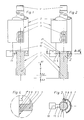
- the upper one is Part of a two-part steering spindle 1 one Motor vehicle partially arranged in a casing tube 2.
- the protruding from the jacket tube upper end 1 ' Steering spindle is not one for the sake of simplicity shown steering wheel positive and / or non-positive connectable.
- the lower end 1 With the lower end 1 "shown, e.g. via a likewise not shown for the sake of simplicity Sliding sleeve not for the sake of simplicity illustrated, associated with the steering gear lower part of the Steering spindle 1 positively connected such that a Axial adjustment of the two parts in relation to each other is feasible.
- Actuator 4 cooperates, whereby the steering shaft 1 in an axial adjustment range a between positions A1 and A2 can be positioned as desired, position A1 being the one End position for the steering shaft 1 represents.
- an intermediate layer that limits the adjustment range a forming position A2 over a magnetic acting Medium 10 - such as a lifting magnet - removable stop 11 assigned to the existing one on the steering shaft Paragraph 1 * cooperates.
- This stop 11 is as one slider having a rectangular cross section trained, the free end in line with the radius of the cross section of the steering shaft 1 is concave.
- the stop 11 forming slide when the steering shaft 1 the position A3 lying outside the adjustment range a has reached in a franking 12 between which the Position A2 defining paragraph 1 * of steering spindle 1 and Radial toothing 5 is present.
- the Steering spindle 1 can also be implemented as a freewheel, to prevent a force on the associated Steering gear is transmitted.
- the steering spindle over the end position A1 moved out, so that the end 1 "with the aforementioned The sliding sleeve comes out of engagement.
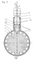
- FIGS. 5-8 of the drawing again the upper part of a two-part steering spindle 1 of a motor vehicle partially in a casing tube 2 arranged, which also protrudes from the jacket tube upper end 1 'of the steering shaft with one for the sake of simplicity Steering wheel, not shown, positive and / or non-positive is connectable.
- the illustrated lower end 1 "is over one also not shown for the sake of simplicity Mechanism of also not for the sake of simplicity illustrated, associated with the steering gear lower part of the Steering spindle 1 positively connected such that one by one Rotary axis 13 radial adjustment alone or in addition to the above-described axial adjustment of the two Parts is feasible.
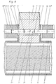
- the position A2 which on the one hand delimits the intermediate adjustment range a, is two positions, each via a magnetic means 10, preferably via two, each in a housing attached to the receiving body 2 * 10 * existing solenoids - assigned removable stops 11, which cooperate with an elongated hole 7 * present in the central region of the blocking member 7, which extends in the direction of the longitudinal axis thereof and is assigned to a guide pin 2a * present on the receiving body.
- These stops 11 are each designed as a rectangular cross-section slide, the free ends 11 'of which engage in the elongated hole 7 * above the guide pin 2a * from opposite sides are provided with bevels 11 "to be regarded as an insertion aid.
- the casing tube 2 is at least a telescopic extension 16 attached to the trigger member 14.
Landscapes
- Engineering & Computer Science (AREA)
- Mechanical Engineering (AREA)
- Chemical & Material Sciences (AREA)
- Combustion & Propulsion (AREA)
- Transportation (AREA)
- Steering Controls (AREA)
- Lock And Its Accessories (AREA)
Description
Problematisch bei einer solchen Ausführungsform ist, daß die Lenkspindel bei in der Praxis vorkommenden Dejustierungen der zugeordneten Schaltmittel unabsichtlich von der Adaptions-Zone in den Blockier-Abschnitt gelangen kann, womit eine beachtliche Gefährdung nicht nur der Fahrzeuginsassen sondern auch der anderen Verkehrsteilnehmer verbunden ist.
- Fig. 1
- eine teilweise geschnittene und teilweise aufgebrochene Ansicht des wesentlichen Teiles der Lenkvorrichtung bei in einer Endlage des in axialer Richtung einstellbaren Verstellbereiches sich befindender Lenkspindel
- Fig. 2
- den Gegenstand nach Fig. 1 bei in einer außerhalb des einstellbaren Verstellbereiches liegenden Position sich befindender Lenkspindel
- Fig. 3
- einen Schnitt durch den Gegenstand nach Fig. 2 gemäß der Linie A-A
- Fig. 4
- eine vergrößert hervorgehobene Einzelheit "Z" des Gegenstandes nach Fig. 2
- Fig. 5
- eine teilweise geschnittene Ansicht des wesentlichen Teiles der Lenkvorrichtung bei in einer Endlage des in radialer Richtung einstellbaren Verstellbereiches sich befindender Lenkspindel
- Fig. 6
- den Gegenstand nach Fig. 5 bei in einer außerhalb des einstellbaren Verstellbereiches liegenden Position sich befindender Lenkspindel
- Fig. 7
- einen vergrößert dargestellten Schnitt durch den Gegenstand nach Fig. 6 gemäß Linie X-X bei einem in Eingriff mit der Radialverzahnung befindlichem Blockierglied
- Fig. 8
- einen vergrößert dargestellten Schnitt durch den Gegenstand nach Fig. 6 gemäß Linie Y-Y (Fig. 7) bei einem nicht in Eingriff mit der Radialverzahnung befindlichem Blockierglied.
Um zu verhindern, daß die Lenkspindel während des Fahrbetriebes des Kraftfahrzeuges in die Sperrposition gelangt, sind der die Zwischenlage darstellenden den vorgegebenen Verstellbereich a einerseits begrenzenden Position A2 zwei jeweils über ein magnetisches Mittel 10-vorzugsweise über zwei jeweils in einem am Aufnahmekörper 2* angebrachten Gehäuse 10* vorhandene Hubmagnete - entfernbare Anschläge 11 zugeordnet, die mit einem im mittleren Bereich des Blockiergliedes 7 vorhandenen Langloch 7* kooperieren, das sich in Richtung der Längsachse desselben erstreckt und einem am Aufnahmekörper vorhandenen Führungszapfen 2a* zugeordnet ist. Diese Anschläge 11 sind jeweils als einen rechteckförmigen Querschnitt aufweisende Schieber ausgebildet, deren in das Langloch 7* oberhalb des Führungszapfens 2a* von sich gegenüberliegenden Seiten eingreifende freie Enden 11' mit als Einführhilfe anzusehenden Schrägen 11" versehen sind.
Claims (26)
- Lenkvorrichtung für Kraftfahrzeuge mit einer zumindest partiell von einem Mantelrohr (2) umgebenen Lenkspindel (1), von der das eine Ende mit einem Lenkrad verbunden und das andere Ende einem Lenkgetriebe zugeordnet ist, und die mittels zumindest einer fremdkraftbetätigten Stellvorrichtung (4) in axialer und/oder radialer Richtung innerhalb eines vorgegebenen, durch zwei Endlagen (A1/A3) begrenzten Gesamtverstellbereiches (a+a') einstellbar ist, welcher Gesamtverstellbereich in einen durch die eine Endlage (A1) und eine Zwischenanlage (A2) begrenzten ersten Verstellbereich (a), in dem eine über das Lenkrad auf die Lenkspindel (1) ausgeübte Torsionskraft auf das Lenkgetriebe übertragbar ist, und einen durch die Zwischenlage (A2) und die andere Endlage (A3) begrenzten zweiten Verstellbereich (a') aufgeteilt ist, wobei die Torsionskraft zumindest in der anderen Endlage (A3) nicht auf das Lenkgetriebe übertragbar ist, dadurch gekennzeichnet, daß die Stellvorrichtung (4) so ausgebildet und/oder so angeordnet ist, daß die Lenkspindel (1) bei in Betrieb befindlichem Kraftfahrzeug aufgrund von zumindest einem in der Zwischenlage (A2) der Lenkspindel (1) zugeordneten, entfernbaren Anschlag (11) nur innerhalb des ersten Verstellbereichs (a) einstellbar ist und daß bei Außerbetriebsetzung des Kraftfahrzeugs die Verstellung der Lenkspindel (1) unter Entfernung des Anschlags (11) über den zweiten Verstellbereich (a') in die andere Endlage (A3) zwangsläufig eingeleitet ist.
- Lenkvorrichtung nach Anspruch 1, dadurch gekennzeichnet, daß in der außerhalb des Verstellbereichs (a) befindlichen Position (A3) die Lenkspindel (1) einem ortsfest im Kraftfahrzeug gehaltenen Blockierglied (7) unter Bildung eines Formschlusses zugeordnet ist.
- Lenkvorrichtung nach Anspruch 2, dadurch gekennzeichnet, daß das Blockierglied (7) an dem die Lenkspindel (1) umgebenden Mantelrohr (2) befestigt ist.
- Lenkvorrichtung nach einem der Ansprüche 1 bis 3, dadurch gekennzeichnet, daß der Formschluß durch eine die Lenkspindel (1) zumindest partiell umgebende, am Blockierglied (7) vorhandene, senkrecht zur Längsachse der Lenkspindel verlaufende Radialverzahnung (6) und eine damit kooperierende, an der Lenkspindel (1) entsprechend vorgesehene Radialverzahnung (5) realisiert ist.
- Lenkvorrichtung nach Anspruch 4, dadurch gekennzeichnet, daß die beiden miteinander kooperierenden Radialverzahnungen (5,6) bei ihrer Zuordnung zueinander an ihren zuerst in Eingriff kommenden Zahnbereichen (5', (6')) dachförmig ausgeführt sind.
- Lenkvorrichtung nach Anspruch 5, dadurch gekennzeichnet, daß die am Blockierglied (7) vorhandene Radialverzahnung (6) in Umfangsrichtung mit einem auf die Zahnbreite abgestimmten geringfügigen Spiel an demselben gehalten ist.
- Lenkvorrichtung nach Anspruch 6, dadurch gekennzeichnet, daß der Spielbereich von einem unter der Einwirkung eines Federelementes (8) stehenden Bauteil (9) beeinflußbar ist.
- Lenkvorrichtung nach einem der Ansprüche 1 bis 7, dadurch gekennzeichnet, daß die Lenkspindel (1) für die Axialverstellung eine zahnstangenartige Axialverzahnung (3) aufweist, und daß einem mit der unteren Endlage (A2) des Verstellbereiches (a) korrespondierenden Absatz (1*) der Lenkspindel (1) ein entfernbarer Anschlag (11) zugeordnet ist.
- Lenkvorrichtung nach Anspruch 8, dadurch gekennzeichnet, daß der Anschlag (11) durch elektromagnetische Mittel (10) entfernbar ist.
- Lenkvorrichtung nach einem der Ansprüche 8 oder 9, dadurch gekennzeichnet, daß der Anschlag (11) als ein einen rechteckförmigen Querschnitt aufweisender Schieber ausgebildet ist.
- Lenkvorrichtung nach Anspruch 10, dadurch gekennzeichnet, daß das der Lenkspindel (1) zugeordnete freie Ende des Schiebers entsprechend dem Radius des Lenkspindel-Querschnitts konkav ausgeführt ist.
- Lenkvorrichtung nach einem der vorhergehenden Ansprüche, dadurch gekennzeichnet, daß zwischen dem mit der unteren Endlage (A3) korrespondierenden Absatz (1*) und der Radialverzahnung (5) ein Freiraum (12) an der Lenkspindel (1) vorhanden ist, in den der Schieber beim Erreichen der außerhalb des Verstellbereichs (a) liegenden Position (A3) quasi spielfrei einfährt.
- Lenkvorrichtung nach einem der vorhergehenden Ansprüche, dadurch gekennzeichnet, daß die Lenkspindel (1) in der außerhalb des Verstellbereiches (a) befindlichen Position nicht mehr mit dem Lenkgetriebe in Eingriff sondern freilaufend ist.
- Lenkvorrichtung nach Anspruch 13, dadurch gekennzeichnet, daß die Lenkspindel (1) in der Nähe der Stellvorrichtung (4) geteilt ausgeführt ist, und daß die beiden Lenkspindelteile in der außerhalb des Verstellbereiches (a) befindlichen Position voneinander entkoppelt sind.
- Lenkvorrichtung nach einem der Ansprüche 1 bis 3, dadurch gekennzeichnet, daß der Formschluß durch eine an der Lenkspindel (1) vorgesehene Radialverzahnung (5) und das radial zur Lenkspindel (1) verstellbare, mit einem keilförmig ausgebildeten Endbereich (7') in die Radialverzahnung (5) eingreifende Blockierglied (7) realisiert ist.
- Lenkvorrichtung nach einem der Ansprüche 1,2 oder 15, dadurch gekennzeichnet, daß die Lenkspindel (1) für ihre zusammen mit dem Mantelrohr (2) erfolgende Radialverstellung über die Stellvorrichtung (4) um eine Schwenkachse (13) bewegbar ist, die von dem dem Lenkrad zugeordneten einen Ende (1') der Lenkspindel entfernt vorhanden ist, daß das am Mantelrohr (2) angeordnete Blockierorgan (7) einem auf den dem keilförmigen einen Endbereich (7') gegenüberliegenden anderen Endbereich (7") einwirkenden, ortsfest gehaltenen Auslöseteil (14) zugeordnet ist und daß das Blockierglied (7) unter der Einwirkung von zumindest einem Federelement (15) derart gehalten ist, daß der keilförmige eine Endbereich (7') bei nicht am Auslöseteil (14) anliegendem anderen Endbereich (7") mit der Radialverzahnung (5) nicht in Eingriff ist.
- Lenkvorrichtung nach Anspruch 16, dadurch gekennzeichnet, daß das Blockierglied (7) in einem am Mantelrohr (2) vorhandenen Aufnahmekörper (2*) untergebracht ist.
- Lenkvorrichtung nach einem der Ansprüche 16 oder 17, dadurch gekennzeichnet, daß das Blockierglied (7) als ein unter der Einwirkung des als Druckfeder ausgebildeten, in dem Aufnahmekörper (2*) angeordneten zumindest einen Federelementes (15) stehendes Riegelorgan ausgebildet ist.
- Lenkvorrichtung nach Anspruch 18, dadurch gekennzeichnet, daß das als Riegelorgan ausgebildete Blockierglied (7) mit einem im Bereich seiner Längsachse vorgesehenen Langloch (7*) versehen ist, das einem im Aufnahmekörper (2*) ortsfest vorhandenen Zapfen (2a*) zugeordnet ist.
- Lenkvorrichtung nach einem der Ansprüche 16 bis 19, dadurch gekennzeichnet, daß das als Riegelorgan ausgebildete Blockierglied (7) mit seinem einen Endbereich (7') im Aufnahmekörper (2*) quasi spielfrei verschiebbar geführt ist und mit seinem anderen Endbereich (7") um einen bestimmten Winkel β bezüglich seiner Längsachse auslenkbar ist.
- Lenkvorrichtung nach einem der Ansprüche 16 bis 20, dadurch gekennzeichnet, daß das Blockierglied (7) zumindest einem entfernbaren Anschlag (11) zugeordnet ist.
- Lenkvorrichtung nach Anspruch 21, dadurch gekennzeichnet, daß zwei jeweils durch elektromagnetische Mittel (10) entfernbare Anschläge (11) vorhanden sind, die jeweils in einem dem Aufnahmekörper (2*) des Blockiergliedes (7) zugeordneten Gehäuse (10*) angeordnet sind.
- Lenkvorrichtung nach Anspruch 22, dadurch gekennzeichnet, daß die Anschläge (11) jeweils als einen rechteckförmigen Querschnitt aufweisende Schieber ausgebildet sind, deren freie Enden (11') dem im Blockierorgan (7) vorhandenen Langloch (7*) zugeordnet sind.
- Lenkvorrichtung nach Anspruch 23, dadurch gekennzeichnet, daß die dem im Blockierorgan (7) vorhandenen Langloch (7*) zugeordneten freien Enden (11') der Schieber mit als Einführhilfe dienenden Schrägen (11") versehen sind.
- Lenkvorrichtung nach Anspruch 24, dadurch gekennzeichnet, daß das Langloch (7*) sich in Richtung der Längsachse der Lenkspindel (1) erstreckt und daß das den elektromagnetischen Mitteln (10) jeweils zugeordnete Gehäuse (10*) am Aufnahmekörper (2*) angebracht ist.
- Lenkvorrichtung nach einem der vorhergehenenden Ansprüche, dadurch gekennzeichnet, daß die Stellvorrichtung (4) elektromotorisch betrieben wird.
Applications Claiming Priority (4)
| Application Number | Priority Date | Filing Date | Title |
|---|---|---|---|
| DE19944429365 DE4429365C1 (de) | 1994-08-19 | 1994-08-19 | Lenkvorrichtung für Kraftfahrzeuge |
| DE4429365 | 1994-08-19 | ||
| DE4436091 | 1994-10-10 | ||
| DE4436091A DE4436091C1 (de) | 1994-10-10 | 1994-10-10 | Lenkvorrichtung für Kraftfahrzeuge |
Publications (3)
| Publication Number | Publication Date |
|---|---|
| EP0697325A2 EP0697325A2 (de) | 1996-02-21 |
| EP0697325A3 EP0697325A3 (de) | 1998-07-08 |
| EP0697325B1 true EP0697325B1 (de) | 2001-10-24 |
Family
ID=25939348
Family Applications (1)
| Application Number | Title | Priority Date | Filing Date |
|---|---|---|---|
| EP95112128A Expired - Lifetime EP0697325B1 (de) | 1994-08-19 | 1995-08-02 | Lenkvorrichtung für Kraftfahrzeuge |
Country Status (3)
| Country | Link |
|---|---|
| EP (1) | EP0697325B1 (de) |
| DE (1) | DE59509739D1 (de) |
| ES (1) | ES2169097T3 (de) |
Families Citing this family (3)
| Publication number | Priority date | Publication date | Assignee | Title |
|---|---|---|---|---|
| DE19524195C1 (de) * | 1995-07-03 | 1996-10-31 | Daimler Benz Ag | Einstellvorrichtung zur Neigungsverstellung eines schwenkbar angelenkten Mantelrohres einer Lenkspindel eines Kraftfahrzeuges |
| SE9804469L (sv) * | 1998-12-21 | 2000-06-22 | Volvo Ab | Anordning vid ett motorfordon |
| JP2021146841A (ja) * | 2020-03-18 | 2021-09-27 | 株式会社アイシン | 車両盗難防止装置 |
Family Cites Families (5)
| Publication number | Priority date | Publication date | Assignee | Title |
|---|---|---|---|---|
| JPH0529979Y2 (de) * | 1987-04-17 | 1993-07-30 | ||
| JP2575855B2 (ja) * | 1988-10-06 | 1997-01-29 | 日産自動車株式会社 | ステアリングホイールの姿勢制御装置 |
| US4997053A (en) * | 1990-02-15 | 1991-03-05 | Clifford Electronics, Inc. | Remote control vehicle seat and steering wheel positioning system |
| EP0499001B1 (de) * | 1991-01-29 | 1995-03-08 | Valeo Securite Habitacle | Steuereinrichtung für eine Lenkverriegelungsvorrichtung |
| US5211042A (en) * | 1991-03-29 | 1993-05-18 | Nissan Motor Co., Ltd. | Steering locking apparatus with tiltable steering mechanism |
-
1995
- 1995-08-02 EP EP95112128A patent/EP0697325B1/de not_active Expired - Lifetime
- 1995-08-02 ES ES95112128T patent/ES2169097T3/es not_active Expired - Lifetime
- 1995-08-02 DE DE59509739T patent/DE59509739D1/de not_active Expired - Fee Related
Also Published As
| Publication number | Publication date |
|---|---|
| ES2169097T3 (es) | 2002-07-01 |
| DE59509739D1 (de) | 2001-11-29 |
| EP0697325A3 (de) | 1998-07-08 |
| EP0697325A2 (de) | 1996-02-21 |
Similar Documents
| Publication | Publication Date | Title |
|---|---|---|
| DE4436091C1 (de) | Lenkvorrichtung für Kraftfahrzeuge | |
| EP1236626B1 (de) | Schloss, insbesondere zum Verriegeln der Lenkspindel eines Kraftfahrzeugs | |
| EP1363815B1 (de) | Schloss, insbesondere zum verriegeln der lenkspindel eines kraftfahrzeugs | |
| EP1110828B1 (de) | Verriegelungsvorrichtung | |
| EP1232921B1 (de) | Verriegelungsvorrichtung | |
| DE69710698T2 (de) | Diebstahlvorrichtung mit Getriebe für eine Fahrzeuglenksäule | |
| EP3354829B1 (de) | Kraftfahrzeug-betätigungsvorrichtung | |
| DE102020122244B4 (de) | Lenkeinrichtung für ein Fahrzeug, Verwendung und Fahrzeug mit Lenkeinrichtung | |
| DE3411054C2 (de) | ||
| EP0901429B1 (de) | Vorrichtung zum verstellen der position eines aussenspiegels | |
| DE10126909A1 (de) | Schließvorrichtung | |
| EP0480159B1 (de) | Vorrichtung zur Erzeugung eines überlagerten Lenkkorrektureingriffs | |
| DE19831205C2 (de) | Stufenloser manueller Antrieb | |
| WO2019114868A1 (de) | Stirnradgetriebe mit sperrmechanismus | |
| WO2009030704A1 (de) | Vorrichtung zur ansteuerung eines sperrgliedes | |
| DE3205415C2 (de) | Einstellvorrichtung für eine in axialer Richtung verstellbare Lenksäule für Kraftfahrzeuge | |
| EP0697325A2 (de) | Lenkvorrichtung für Kraftfahrzeuge | |
| EP1242267B1 (de) | Vorrichtung zum sperren der lenkspindel eines kraftfahrzeugs | |
| DE4429365C1 (de) | Lenkvorrichtung für Kraftfahrzeuge | |
| DE10260548B4 (de) | Antrieb für einen Fahrzeugsitzeinsteller | |
| DE4108955A1 (de) | Verstelleinrichtung, insbesondere zum einstellen von fahrzeugsitzen | |
| DE2227561C2 (de) | Diebstahlsicherung an der Lenksäule eines Kraftfahrzeuges | |
| DE19816248C1 (de) | Lehneneinstellbeschlag für einen Fahrzeugsitz | |
| DE2749158A1 (de) | Lenkschloss fuer kraftfahrzeuge | |
| DE3433600C2 (de) | Vorrichtung zum Steuern der Verschiebe- und Ausstellbewegung des Deckels von Schiebehebedächern |
Legal Events
| Date | Code | Title | Description |
|---|---|---|---|
| PUAI | Public reference made under article 153(3) epc to a published international application that has entered the european phase |
Free format text: ORIGINAL CODE: 0009012 |
|
| AK | Designated contracting states |
Kind code of ref document: A2 Designated state(s): DE ES FR GB IT SE |
|
| PUAL | Search report despatched |
Free format text: ORIGINAL CODE: 0009013 |
|
| AK | Designated contracting states |
Kind code of ref document: A3 Designated state(s): DE ES FR GB IT SE |
|
| 17P | Request for examination filed |
Effective date: 19980818 |
|
| 17Q | First examination report despatched |
Effective date: 19991208 |
|
| GRAG | Despatch of communication of intention to grant |
Free format text: ORIGINAL CODE: EPIDOS AGRA |
|
| GRAG | Despatch of communication of intention to grant |
Free format text: ORIGINAL CODE: EPIDOS AGRA |
|
| GRAH | Despatch of communication of intention to grant a patent |
Free format text: ORIGINAL CODE: EPIDOS IGRA |
|
| GRAH | Despatch of communication of intention to grant a patent |
Free format text: ORIGINAL CODE: EPIDOS IGRA |
|
| GRAA | (expected) grant |
Free format text: ORIGINAL CODE: 0009210 |
|
| AK | Designated contracting states |
Kind code of ref document: B1 Designated state(s): DE ES FR GB IT SE |
|
| REF | Corresponds to: |
Ref document number: 59509739 Country of ref document: DE Date of ref document: 20011129 |
|
| REG | Reference to a national code |
Ref country code: GB Ref legal event code: IF02 |
|
| GBT | Gb: translation of ep patent filed (gb section 77(6)(a)/1977) |
Effective date: 20020123 |
|
| ET | Fr: translation filed | ||
| REG | Reference to a national code |
Ref country code: ES Ref legal event code: FG2A Ref document number: 2169097 Country of ref document: ES Kind code of ref document: T3 |
|
| PLBE | No opposition filed within time limit |
Free format text: ORIGINAL CODE: 0009261 |
|
| STAA | Information on the status of an ep patent application or granted ep patent |
Free format text: STATUS: NO OPPOSITION FILED WITHIN TIME LIMIT |
|
| 26N | No opposition filed | ||
| PGFP | Annual fee paid to national office [announced via postgrant information from national office to epo] |
Ref country code: DE Payment date: 20050709 Year of fee payment: 11 |
|
| PGFP | Annual fee paid to national office [announced via postgrant information from national office to epo] |
Ref country code: FR Payment date: 20050801 Year of fee payment: 11 |
|
| PGFP | Annual fee paid to national office [announced via postgrant information from national office to epo] |
Ref country code: GB Payment date: 20050802 Year of fee payment: 11 |
|
| PGFP | Annual fee paid to national office [announced via postgrant information from national office to epo] |
Ref country code: ES Payment date: 20050804 Year of fee payment: 11 |
|
| PGFP | Annual fee paid to national office [announced via postgrant information from national office to epo] |
Ref country code: SE Payment date: 20050822 Year of fee payment: 11 |
|
| PG25 | Lapsed in a contracting state [announced via postgrant information from national office to epo] |
Ref country code: SE Free format text: LAPSE BECAUSE OF NON-PAYMENT OF DUE FEES Effective date: 20060803 |
|
| PGFP | Annual fee paid to national office [announced via postgrant information from national office to epo] |
Ref country code: IT Payment date: 20060831 Year of fee payment: 12 |
|
| PG25 | Lapsed in a contracting state [announced via postgrant information from national office to epo] |
Ref country code: DE Free format text: LAPSE BECAUSE OF NON-PAYMENT OF DUE FEES Effective date: 20070301 |
|
| EUG | Se: european patent has lapsed | ||
| GBPC | Gb: european patent ceased through non-payment of renewal fee |
Effective date: 20060802 |
|
| REG | Reference to a national code |
Ref country code: FR Ref legal event code: ST Effective date: 20070430 |
|
| REG | Reference to a national code |
Ref country code: ES Ref legal event code: FD2A Effective date: 20060803 |
|
| PG25 | Lapsed in a contracting state [announced via postgrant information from national office to epo] |
Ref country code: GB Free format text: LAPSE BECAUSE OF NON-PAYMENT OF DUE FEES Effective date: 20060802 |
|
| PG25 | Lapsed in a contracting state [announced via postgrant information from national office to epo] |
Ref country code: ES Free format text: LAPSE BECAUSE OF NON-PAYMENT OF DUE FEES Effective date: 20060803 |
|
| PG25 | Lapsed in a contracting state [announced via postgrant information from national office to epo] |
Ref country code: FR Free format text: LAPSE BECAUSE OF NON-PAYMENT OF DUE FEES Effective date: 20060831 |
|
| PG25 | Lapsed in a contracting state [announced via postgrant information from national office to epo] |
Ref country code: IT Free format text: LAPSE BECAUSE OF NON-PAYMENT OF DUE FEES Effective date: 20070802 |