EP0697272A2 - Method and apparatus for making composite bathtubs - Google Patents
Method and apparatus for making composite bathtubs Download PDFInfo
- Publication number
- EP0697272A2 EP0697272A2 EP95110909A EP95110909A EP0697272A2 EP 0697272 A2 EP0697272 A2 EP 0697272A2 EP 95110909 A EP95110909 A EP 95110909A EP 95110909 A EP95110909 A EP 95110909A EP 0697272 A2 EP0697272 A2 EP 0697272A2
- Authority
- EP
- European Patent Office
- Prior art keywords
- steel
- inner shell
- frame
- drawing table
- outer shell
- Prior art date
- Legal status (The legal status is an assumption and is not a legal conclusion. Google has not performed a legal analysis and makes no representation as to the accuracy of the status listed.)
- Granted
Links
Images


Classifications
-
- B—PERFORMING OPERATIONS; TRANSPORTING
- B29—WORKING OF PLASTICS; WORKING OF SUBSTANCES IN A PLASTIC STATE IN GENERAL
- B29C—SHAPING OR JOINING OF PLASTICS; SHAPING OF MATERIAL IN A PLASTIC STATE, NOT OTHERWISE PROVIDED FOR; AFTER-TREATMENT OF THE SHAPED PRODUCTS, e.g. REPAIRING
- B29C70/00—Shaping composites, i.e. plastics material comprising reinforcements, fillers or preformed parts, e.g. inserts
- B29C70/68—Shaping composites, i.e. plastics material comprising reinforcements, fillers or preformed parts, e.g. inserts by incorporating or moulding on preformed parts, e.g. inserts or layers, e.g. foam blocks
- B29C70/84—Shaping composites, i.e. plastics material comprising reinforcements, fillers or preformed parts, e.g. inserts by incorporating or moulding on preformed parts, e.g. inserts or layers, e.g. foam blocks by moulding material on preformed parts to be joined
-
- A—HUMAN NECESSITIES
- A47—FURNITURE; DOMESTIC ARTICLES OR APPLIANCES; COFFEE MILLS; SPICE MILLS; SUCTION CLEANERS IN GENERAL
- A47K—SANITARY EQUIPMENT NOT OTHERWISE PROVIDED FOR; TOILET ACCESSORIES
- A47K3/00—Baths; Douches; Appurtenances therefor
- A47K3/02—Baths
-
- B—PERFORMING OPERATIONS; TRANSPORTING
- B29—WORKING OF PLASTICS; WORKING OF SUBSTANCES IN A PLASTIC STATE IN GENERAL
- B29C—SHAPING OR JOINING OF PLASTICS; SHAPING OF MATERIAL IN A PLASTIC STATE, NOT OTHERWISE PROVIDED FOR; AFTER-TREATMENT OF THE SHAPED PRODUCTS, e.g. REPAIRING
- B29C44/00—Shaping by internal pressure generated in the material, e.g. swelling or foaming ; Producing porous or cellular expanded plastics articles
- B29C44/02—Shaping by internal pressure generated in the material, e.g. swelling or foaming ; Producing porous or cellular expanded plastics articles for articles of definite length, i.e. discrete articles
- B29C44/12—Incorporating or moulding on preformed parts, e.g. inserts or reinforcements
- B29C44/14—Incorporating or moulding on preformed parts, e.g. inserts or reinforcements the preformed part being a lining
Definitions
- the present invention relates to a method and an apparatus for producing composite bathtubs with the features according to the preamble of the main claim.
- Composite bathtubs in the sense of the application can consist of an inner shell made of plastic and an outer shell made of steel with an intermediate filler. While the outer shell made of steel is used in particular for stabilization, the inner shell made of plastic should meet the sanitary requirements.
- the filler is said to improve stability and to provide heat and sound insulation.
- the object of the invention is to provide practical solutions for the economical production of composite bathtubs of this type.
- the plastic shell on the one hand and the steel shell on the other hand are first produced in a conventional manner in a mold corresponding to the bath, by deep-drawing, with the further necessary operations such as pickling, enamelling, etc. following.
- the plastic shell is first reversed, ie with the edge of the tub facing downwards, with its edge placed on the base plate of a clamping tool, it being positioned by a support frame.
- the prepared steel pan is then turned up and adjusted. Spacers ensure an even space between the two shells which is approximately 3 mm.
- the two trays are then clamped all around by a clamping tool.
- a sealing frame of this tool is designed so that the Continues space between the two shells all around next to the collar of the plastic shell in the form of a circumferential and sealed annular space that adjoins the space.
- the filler preferably polyurethane
- the filler is injected into the drain opening of the steel shell.
- the circumferential annular space next to the collar of the plastic tub is connected to a vacuum.
- the liquid plastic that is introduced at certain points is immediately pulled towards the edge by the vacuum, so that it is distributed evenly over the entire tub surface.
- the composite bathtubs consist of two interconnected shells, namely an inner shell made of plastic and an outer shell made of steel.
- an inner shell made of plastic and an outer shell made of steel.
- Claim 9 relates to a preferred device for performing this method.
- the outer shell is first formed from steel by deep drawing in a conventional manner. Small holes are drilled in this steel blank in the lower area. Then this steel blank is placed in a deformation drawing table which has a space below the steel blank which can be evacuated via a vacuum pump. A thermoplastic acrylic plate is then placed on the drawing table and clamped there by means of a frame which can consist of a lower frame and an upper frame and which can also be pivotable. When applying a vacuum, you can now pull the deformable acrylic sheet into the steel blank and adjust the contour of the tub, taking the steel blank beforehand an adhesive was applied so that the inner shell made of acrylic is glued to the outer shell made of steel and a good bond is produced.
- a reaction adhesive is preferably used as the adhesive, e.g. can be sprayed on and then activated by the heat contained in the acrylic plate when the acrylic plate comes into contact with the steel blank.
- a deformation drawing table is preferably used, which can be raised or lowered hydraulically, so that the tub rim can be formed into the plastic acrylic plate by a relative movement of the deformation drawing table relative to the frame by means of which the acrylic plate is clamped.
- Subclaim 9 has a device for content, which is preferably used to carry out the method according to this alternative of the invention.
- 1 and 2 consists of an inner shell 1 made of plastic, for example acrylic, and the outside of an outer shell 2 made of steel.
- the space between the inner shell and outer shell, which is approximately in the 3 mm range, is filled with a filler 3, preferably made of polyurethane.
- a vertical collar 1a adjoins the horizontal edge, as can be seen in FIG. 2.
- the filler 3 also continues in this area through a collar 3a. However, such a collar is missing in the outer shell 2. Drain openings 1b and 2a are formed both on the inner shell and on the outer shell.
- both the inner shell and the outer shell are produced as blanks in the form shown in FIGS. 1 and 2 by deep drawing.
- a tensioning tool is provided, consisting of a base plate 10 with a support frame 11, a block frame 12, all around corresponding to the plan shape of the trough and a sealing frame 13 which is also rectangular in section and also runs all the way round.
- the method begins with the thermoformed, milled and cleaned inner shell 1 made of plastic with its edge placed on the base plate 10, the adapted support frame 11 being used for positioning.
- the collar 1a of the inner shell lies directly next to the surrounding block frame 12.
- the next step in the process is that the deep-drawn, pickled and enamelled outer shell 2 made of steel is turned over, as shown. It is adjusted in such a way that with the help of spacers between the two shells an even space remains in the 3mm range.
- Both shells are then clamped all around using a sealing frame 13 with a horizontal leg 13a and a vertical leg 13b.
- the horizontal leg 13a is supported on two sealing cords 17, which in turn lie on the block frame 12, a vacuum chamber 16 being formed between the sealing cords.
- the vertical leg 13b exerts pressure on the two shells 1 and 2 via a further sealing cord 15.
- a circumferential and sealed annular space 14 is formed between the vertical leg 13b and the collar 1a of the inner shell, which adjoins the space between the connects both shells.
- the annular space 14 is provided all around with vacuum connections 14a.
- the next process step consists of injecting polyurethane as a casting resin into the drain opening of the steel trough 2b, a vacuum being simultaneously generated via lines 14a in the annular space between the horizontal leg 13a and the collar 1a.
- the injected mass is distributed quickly and evenly in the space between the two shells. It also reaches the annular space 14 next to the collar 3a of the inner tub.
- FIGS. 4 and 5 In the following, reference is made to FIGS. 4 and 5 and a further alternative method according to the invention is explained.
- the steel blank 23 is deep drawn as before, the drain 27 is pushed through and drilled but without an overflow hole. Then a 1 mm Bohrung hole 22 is made in the radius-bottom wall, in the middle, for example by laser technology, approximately every 5 cm.
- the steel blank 23 is then pickled and passivated. Reaction adhesive is sprayed evenly and cleanly onto the entire inner surface of the steel trough 23. After the solvents have evaporated, the blank is then placed in a shaping drawing table 28. This can be moved hydraulically. All of the bores 22, including the drain hole 27, lie in an open vacuum channel 21, which fits the drawing table 28 with a precise fit. This channel is sealed to the tub body by a neoprene seal or the like.
- thermoplastic acrylic plate 24 is placed on the drawing table 28, directly over the inserted steel blank 23.
- a suitable apparatus for example a convection oven or quartz heater
- the plastic acrylic plate 24 is clamped hydraulically or pneumatically.
- the drawing table 28 is about 50 mm relative to the frame 25, 26 raised.
- the tub edge is formed into the clamped plastic acrylic plate by the downward movement.
- a vacuum pump installed on the tub rim immediately evacuates the air enclosed in the tub body via the bores 22. This pulls the soft acrylic plate 24 into the body of the steel blank 23 and adapts exactly to the tub contour.
- the reaction adhesive 30 is now activated by the heat still present in the acrylic.
- the outer shell 23 made of steel is preferably provided with an anti-rust layer 31 on the outside.
Abstract
Description
Die vorliegende Erfindung bezieht sich auf ein Verfahren und auf eine Vorrichtung zur Herstellung von Verbund-Badewannen mit den Merkmalen nach dem Oberbegriff des Hauptanspruchs.The present invention relates to a method and an apparatus for producing composite bathtubs with the features according to the preamble of the main claim.
Verbund-Badewannen im Sinne der Anmeldung können bestehen aus einer Innenschale aus Kunststoff und einer Außenschale aus Stahl mit einem dazwischenliegenden Füllstoff. Während die Außenschale aus Stahl, insbesondere zur Stabilisierung dient, soll die Innenschale aus Kunststoff den sanitären Ansprüchen genügen. Der Füllstoff soll die Stabilität verbessern und zur Wärme- bzw. Schallisolierung dienen.Composite bathtubs in the sense of the application can consist of an inner shell made of plastic and an outer shell made of steel with an intermediate filler. While the outer shell made of steel is used in particular for stabilization, the inner shell made of plastic should meet the sanitary requirements. The filler is said to improve stability and to provide heat and sound insulation.
Im Prinzip ist der Aufbau einer derartigen Verbund-Badewanne aus der DE-OS 26 18 070 bekannt.In principle, the construction of such a composite bathtub is known from DE-OS 26 18 070.
Die Aufgabe der Erfindung besteht in praktikablen Lösungsvorschlägen für eine wirtschaftliche Herstellung derartiger Verbund-Badewannen.The object of the invention is to provide practical solutions for the economical production of composite bathtubs of this type.
Diese Aufgabe wird durch ein Verfahren nach dem Hauptanspruch gelöst. Die Unteransprüche 2 und 3 haben bevorzugte Vorrichtungen zur Durchführung dieses Verfahrens zum Inhalt.This object is achieved by a method according to the main claim. The
Bei diesem erfindungsgemäßen Verfahren werden zunächst die Kunststoffschale einerseits und die Stahlschale andererseits in herkömmlicher Weise in einer der Badewanne entsprechenden Form durch Tiefziehen hergestellt, wobei sich die weiteren erforderlichen Arbeitsgänge wie Beizen, Emaillieren usw. anschließen. Um die Verbindung herzustellen wird zunächst die Kunststoffschale umgekehrt, d.h. mit dem Wannenrand nach unten mit ihrem Rand auf die Grundplatte eines Spannwerkzeuges aufgelegt, wobei sie durch ein Stützgestell positioniert wird. Die vorbereitete Stahlwanne wird dann aufgestülpt und justiert. Abstandshalter gewährleisten einen gleichmäßigen Zwischenraum zwischen den beiden Schalen der im Bereich von 3 mm etwa liegt. Die beiden Wannen werden alsdann ringsum durch ein Spannwerkzeug eingespannt. Dabei ist ein Dichtungsrahmen dieses Werkzeugs so ausgebildet, daß sich der Zwischenraum zwischen den beiden Schalen ringsum neben dem Kragen der Kunststoffschale in Form eines umlaufenden und abgedichteten Ringraumes fortsetzt, der an dem Zwischenraum anschließt. Der Füllstoff, vorzugsweise Polyurethan wird in die Abflußöffnung der Stahlschale injiziert. Gleichzeitig wird dabei der umlaufende Ringraum neben dem Kragen der Kunststoffwanne an ein Vakuum angeschlossen. Durch das Vakuum wird der punktuell eingeführte flüssige Kunststoff unverzüglich zum Rand hin gezogen, so daß er sich gleichmäßig über die gesamte Wannenfläche verteilt. Die Wirtschaftlichkeit des Verfahrens nach der Erfindung ergibt sich nicht nur durch die Qualität des Erzeugnisses, sondern auch durch den geringen Zeitaufwand des eigentlichen Verfahrens und der Rüstzeiten.In this method according to the invention, the plastic shell on the one hand and the steel shell on the other hand are first produced in a conventional manner in a mold corresponding to the bath, by deep-drawing, with the further necessary operations such as pickling, enamelling, etc. following. In order to establish the connection, the plastic shell is first reversed, ie with the edge of the tub facing downwards, with its edge placed on the base plate of a clamping tool, it being positioned by a support frame. The prepared steel pan is then turned up and adjusted. Spacers ensure an even space between the two shells which is approximately 3 mm. The two trays are then clamped all around by a clamping tool. A sealing frame of this tool is designed so that the Continues space between the two shells all around next to the collar of the plastic shell in the form of a circumferential and sealed annular space that adjoins the space. The filler, preferably polyurethane, is injected into the drain opening of the steel shell. At the same time, the circumferential annular space next to the collar of the plastic tub is connected to a vacuum. The liquid plastic that is introduced at certain points is immediately pulled towards the edge by the vacuum, so that it is distributed evenly over the entire tub surface. The economy of the method according to the invention results not only from the quality of the product, but also from the short time required for the actual method and the set-up times.
Ein weiteres Verfahren zur Herstellung von Verbundbadewannen gemäß der Erfindung wird nachfolgend beschrieben. Bei diesem Verfahren bestehen die Verbundbadewannen aus zwei miteinander verbundenen Schalen, nämlich einer Innenschale aus Kunststoff und einer Außenschale aus Stahl. Ein solches Verfahren ist in Anspruch 4 beschrieben. Die Unteransprüche 5 bis 8 haben weitere Ausgestaltungen dieses Verfahrens zum Inhalt. Unteranspruch 9 trifft eine bevorzugte Vorrichtung zur Durchführung dieses Verfahrens.Another method of manufacturing composite bathtubs according to the invention is described below. In this method, the composite bathtubs consist of two interconnected shells, namely an inner shell made of plastic and an outer shell made of steel. Such a method is described in claim 4. The dependent claims 5 to 8 have further refinements of this method. Claim 9 relates to a preferred device for performing this method.
Auch bei diesem Verfahren wird zunächst auf herkömmliche Art die Außenschale aus Stahl durch Tiefziehen geformt. In diesen Stahlrohling werden im unteren Bereich kleine Bohrungen angebracht. Dann wird dieser Stahlrohling in einen Verformungs-Ziehtisch eingelegt, der einen Raum unterhalb des Stahlrohlings aufweist, der über eine Vakuumpumpe evakuiert werden kann. Auf den Ziehtisch wird dann eine thermoplastische Acrylplatte aufgelegt und dort mittels eines Rahmens, der aus einem unteren Rahmen und einem oberen Rahmen bestehen kann und der außerdem schwenkbar sein kann, verspannt. Bei Anlegen eines Vakuums kann man nun die verformbare Acrylplatte in den Stahlrohling hineinziehen und der Wannenkontur anpassen, wobei vorher auf den Stahlrohling ein Klebstoff aufgebracht wurde, so daß die Innenschale aus Acryl mit der Außenschale aus Stahl verklebt und ein guter Verbund hergestellt wird.With this method, too, the outer shell is first formed from steel by deep drawing in a conventional manner. Small holes are drilled in this steel blank in the lower area. Then this steel blank is placed in a deformation drawing table which has a space below the steel blank which can be evacuated via a vacuum pump. A thermoplastic acrylic plate is then placed on the drawing table and clamped there by means of a frame which can consist of a lower frame and an upper frame and which can also be pivotable. When applying a vacuum, you can now pull the deformable acrylic sheet into the steel blank and adjust the contour of the tub, taking the steel blank beforehand an adhesive was applied so that the inner shell made of acrylic is glued to the outer shell made of steel and a good bond is produced.
Dabei verwendet man vorzugsweise einen Reaktionskleber als Klebstoff, der z.B. aufgesprüht werden kann und der dann durch in der Acrylplatte enthaltene Wärme aktiviert wird, wenn die Acrylplatte mit dem Stahlrohling in Berührung kommt.A reaction adhesive is preferably used as the adhesive, e.g. can be sprayed on and then activated by the heat contained in the acrylic plate when the acrylic plate comes into contact with the steel blank.
Vorzugsweise verwendet man einen Verformungs-Ziehtisch, der hydraulisch anhebbar bzw. absenkbar ist, so daß man durch eine Relativbewegung des Verformungs-Ziehtischs gegenüber dem Rahmen, mittels dessen die Acrylplatte eingespannt ist, den Wannenrand in die plastische Acrylplatte formen kann.A deformation drawing table is preferably used, which can be raised or lowered hydraulically, so that the tub rim can be formed into the plastic acrylic plate by a relative movement of the deformation drawing table relative to the frame by means of which the acrylic plate is clamped.
Bei Anlegen des Vakuums kann die Luft im Wannenraum durch die vorher in dem Stahlrohling angebrachten Bohrungen und den Wannenabfluß abgesaugt werden, wobei die Bohrungen relativ klein sein sollten, z.B. mit einem Durchmesser in der Größenordnung vom etwa 1 mm. Das vorgenannte alternative Verfahren gemäß der Erfindung ermöglicht eine besonders einfache Herstellung einer Verbundbadewanne aus zwei Werkstoffschichten, nämlich einer Innenschale aus Kunststoff und einer Außenschale aus Stahl, wobei insbesondere bei Verwendung eines Reaktionsklebers eine gute Haftung erzielt wird. Unteranspruch 9 hat eine Vorrichtung zum Inhalt, die bevorzugt zur Durchführung des Verfahrens gemäß dieser Alternative der Erfindung eingesetzt wird.When the vacuum is applied, the air in the tub space can be sucked out through the bores previously made in the steel blank and the tub drain, the bores being relatively small, for example with a diameter of the order of about 1 mm. The aforementioned alternative method according to the invention enables a particularly simple production of a composite bathtub from two layers of material, namely an inner shell made of plastic and an outer shell made of steel, good adhesion being achieved in particular when using a reaction adhesive. Subclaim 9 has a device for content, which is preferably used to carry out the method according to this alternative of the invention.
Im folgenden wird anhand der beiliegenden Zeichnungen ein Ausführungsbeispiel der Erfindung beschrieben.
- Fig. 1
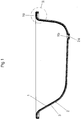
- zeigt im Prinzip einen Längsschnitt durch eine Verbundbadewanne;
- Fig. 2
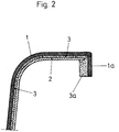
- zeigt einen Schnitt des Bereichs II von Fig. 1 in vergrößertem Maßstab;
- Fig. 3
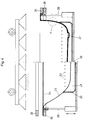
- zeigt einen Schnitt durch ein Einspannwerkzeug,wie es bei der Durchführung des erfindungsgemäßen Verfahren angewandt werden kann;
- Fig. 4
- zeigt im Prinzip einen Längsschnitt durch eine Verbundbadewanne gemäß einer alternativen Ausführungsform der Erfindung;
- Fig. 5
- zeigt einen Schnitt des Bereichs V von Fig. 4 in vergrößertem Maßstab.
- Fig. 1
- shows in principle a longitudinal section through a composite bathtub;
- Fig. 2
- shows a section of area II of Figure 1 on an enlarged scale;
- Fig. 3
- shows a section through a clamping tool, as it can be used in carrying out the method according to the invention;
- Fig. 4
- shows in principle a longitudinal section through a composite bathtub according to an alternative embodiment of the invention;
- Fig. 5
- shows a section of the area V of Fig. 4 on an enlarged scale.
Zunächst wird auf Fig. 1 und 2 Bezug genommen.First, reference is made to FIGS. 1 and 2.
Die fertiggestellte Verbundbadewanne gemäß Fig. 1 und 2 besteht innen aus einer Innenschale 1 aus Kunststoff, beispielsweise Acryl und außen aus einer Außenschale 2 aus Stahl. Der Zwischenraum zwischen Innenschale und Außenschale, der etwa im 3 mm Bereich liegt, ist mit einem Füllstoff 3, vorzugsweise aus Polyurethan ausgefüllt.1 and 2 consists of an
Bei der Innenschale 1 schließt sich an den horizontalen Rand ein lotrechter Kragen 1a an, wie aus Figur 2 ersichtlich. Der Füllstoff 3 setzt sich in diesem Bereich ebenfalls durch einen Kragen 3a fort. Bei der Außenschale 2 indessen, fehlt ein solcher Kragen. Sowohl an der Innenschale, als auch an der Außenschale sind Abflußöffnungen 1b bzw. 2a gebildet.In the
Bei der erfindungsgemäßen Herstellung werden sowohl Innenschale als auch Außenschale als Rohlinge in der auf Fig. 1 und 2 dargestellten Form durch Tiefziehen hergestellt.In the production according to the invention, both the inner shell and the outer shell are produced as blanks in the form shown in FIGS. 1 and 2 by deep drawing.
Im folgenden wird anhand von Figur 3 das Herstellungsverfahren erläutert. Es ist dabei ein Spannwerkzeug vorgesehen, bestehend aus einer Grundplatte 10 mit einem Stützgestell 11, einem Blockrahmen 12, umlaufend entsprechend der Grundrißform der Wanne und einem im Schnitt rechtwinkligen, ebenfalls umlaufenden Dichtungsrahmen 13.The manufacturing method is explained below with reference to FIG. 3. A tensioning tool is provided, consisting of a
Das Verfahren beginnt damit, daß die tiefgezogene, auf fertige Höhe gefräste und gereinigte Innenschale 1 aus Kunststoff mit ihrem Rand auf die Grundplatte 10 aufgelegt wird, wobei das angepaßte Stützgestell 11 zur Positionierung dient. Der Kragen 1a der Innenschale liegt dabei unmittelbar neben dem umlaufenden Blockrahmen 12.The method begins with the thermoformed, milled and cleaned
Der nächste Verfahrenschritt besteht darin, daß die tiefgezogene, gebeizte und rückseitig grundemailierte Außenschale 2 aus Stahl, wie dargestellt aufgestülpt wird. Sie wird derart justiert, daß mit Hilfe von Abstandshaltern zwischen den beiden Schalen ein gleichmäßiger Zwischenraum im 3mm Bereich bleibt.The next step in the process is that the deep-drawn, pickled and enamelled
Beide Schalen werden dann ringsum mit Hilfe eines Dichtungsrahmens 13 mit einem horizontalen Schenkel 13a und einem vertikalen Schenkel 13b eingespannt. Der horizontale Schenkel 13a stützt sich dabei auf zwei Dichtungsschnüre 17 ab, die ihrerseits auf dem Blockrahmen 12 liegen, wobei zwischen den Dichtungsschnüren eine Vakuumkammer 16 gebildet ist. Der vertikale Schenkel 13b übt über eine weitere Dichtungsschnur 15 auf die beiden Schalen 1 und 2 einen Druck aus. Zwischen dem vertikalen Schenkel 13b und dem Kragen 1a der Innenschale ist ein umlaufender und abgedichteter Ringraum 14 gebildet, der an den Zwischenraum zwischen den beiden Schalen anschließt. Der Ringraum 14 ist umlaufendend mit Vakuum-Anschlüssen 14a versehen.Both shells are then clamped all around using a
Der nächste Verfahrensschritt besteht darin, daß Polyurethan als Gießharz in die Abflußöffnung der Stahlwanne 2b injiziert wird, wobei gleichzeitig über Leitungen 14a im Ringraum zwischen dem horizontalen Schenkel 13a und dem Kragen 1a ein Vakuum erzeugt wird. Die injizierte Masse verteilt sich dadurch schnell und gleichmäßig im Zwischenraum zwischen den beiden Schalen. Sie gelangt ebenso in den Ringraum 14 neben den Kragen 3a der Innenwanne.The next process step consists of injecting polyurethane as a casting resin into the drain opening of the steel trough 2b, a vacuum being simultaneously generated via lines 14a in the annular space between the
Nachfolgend wird auf die Figuren 4 und 5 Bezug genommen und ein weiteres alternatives Verfahren gemäß der Erfindung erläutert.In the following, reference is made to FIGS. 4 and 5 and a further alternative method according to the invention is explained.
Der Stahlrohling 23 wird wie bisher tiefgezogen, der Abfluß 27 wird durchgedrückt und gebohrt aber ohne Überlaufbohrung. Danach wird in dem Radius-Boden-Wand, mittig z.B. durch Laser-Technik etwa alle 5 cm eine 1 mm ⌀ große Bohrung 22 durchgeführt. Danach wird der Stahlrohling 23 gebeizt und passiviert. Reaktionskleber wird gleichmäßig und sauber auf die gesamte Innenfläche der Stahlwanne 23 aufgesprüht. Nach dem Abdunsten der Lösungsmittel wird dann der Rohling in einen Verformungs-Ziehtisch 28 eingelegt. Dieser kann hydraulisch bewegt werden. Alle Bohrungen 22 einschließlich der Ablaufbohrung 27 liegen in einem paßgenau zum Ziehtisch 28 gehörenden offenen Vakuumkanal 21. Zum eingesetzten Wannenkörper wird dieser Kanal durch eine Neopren-Dichtung oder dergleichen abgedichtet. Nun wird aus einer dazu geeigneten Apparatur, z.B. einem Umluftofen oder Quarzstrahler kommend eine thermoplastische Acrylplatte 24 auf den Ziehtisch 28 gelegt, unmittelbar über den eingesetzten Stahlrohling 23. Durch einen oberen schwenkbaren Rahmen 25 und einen unteren Rahmen 26, der als passende Maske zum Rohling ausgebildet ist, wird die plastische Acrylplatte 24 hydraulisch oder pneumatisch festgespannt. Danach wird der Ziehtisch 28 gegenüber dem Rahmen 25, 26 etwa 50 mm angehoben. Durch die Abwärtsbewegung wird der Wannenrand in die eingespannte plastische Acrylplatte geformt. Eine am Wannenrand installierte Vakuumpumpe evakuiert nun unmittelbar danach die im Wannenkörper eingeschlossene Luft über die Bohrungen 22. Dadurch wird die weiche Acrylplatte 24 in den Körper des Stahlrohlings 23 hineingezogen und paßt sich genau der Wannenkontur an. Der Reaktionskleber 30 wird nun durch die noch im Acryl vorhandene Wärme aktiviert. Er verbindet sich mit der Acryl-Kontaktfläche, polymerisiert und stellt dadurch einen optimalen Verbund Stahl-Acryl her. Bei der nun im Stahlrohling tiefgezogenen Acrylwanne setzt während der Abkühlphase der Schrumpf ein. D.h. die Acrylwanne nimmt in der Länge und Breite um ca. 0,5% ab. Diese "Verkleinerung" der Wanne wird durch einen hydraulisch bewegten "Wannenrandschieber" ermöglicht, der ca. 1 Minute nach Verformungsbeginn aus dem Werkzeug (Stahlrohling plus hydraulisch bewegten Wannenschieber) schräg nach unten herausgefahren wird. Der Schrumpf hat nun freie Bewegung. In einer zweiten Version, vorzugsweise bei runden Wannen, kann dieser Schrumpf auch zur Erhöhung der Verbundfestigkeit genutzt werden. Eine allseits gleichmäßige Abkühlung ist wichtig und in der Praxis nicht ganz einfach erreichbar.The
Die Außenschale 23 aus Stahl wird vorzugsweise außen mit einer Rostschutzschicht 31 versehen.The
Claims (9)
Applications Claiming Priority (4)
| Application Number | Priority Date | Filing Date | Title |
|---|---|---|---|
| DE4428896 | 1994-08-18 | ||
| DE4428896 | 1994-08-18 | ||
| DE4431716A DE4431716C3 (en) | 1994-08-18 | 1994-09-06 | Method and device for producing composite bathtubs |
| DE4431716 | 1994-09-06 |
Publications (3)
| Publication Number | Publication Date |
|---|---|
| EP0697272A2 true EP0697272A2 (en) | 1996-02-21 |
| EP0697272A3 EP0697272A3 (en) | 1996-04-17 |
| EP0697272B1 EP0697272B1 (en) | 1997-09-24 |
Family
ID=25939242
Family Applications (1)
| Application Number | Title | Priority Date | Filing Date |
|---|---|---|---|
| EP95110909A Expired - Lifetime EP0697272B1 (en) | 1994-08-18 | 1995-07-12 | Method and apparatus for making composite bathtubs |
Country Status (3)
| Country | Link |
|---|---|
| EP (1) | EP0697272B1 (en) |
| AT (1) | ATE158534T1 (en) |
| DE (1) | DE9422399U1 (en) |
Cited By (3)
| Publication number | Priority date | Publication date | Assignee | Title |
|---|---|---|---|---|
| WO2001047695A1 (en) * | 1999-12-23 | 2001-07-05 | Saab Ab | A holding device for holding an article and a plant for heat treatment of an article |
| DE4431716C3 (en) * | 1994-08-18 | 2003-04-10 | Kaldewei Franz Gmbh & Co | Method and device for producing composite bathtubs |
| EP2025273A1 (en) * | 2003-07-25 | 2009-02-18 | Kohler Mira Limited | Composite articles and method of manufacture |
Families Citing this family (1)
| Publication number | Priority date | Publication date | Assignee | Title |
|---|---|---|---|---|
| DE102009011170A1 (en) | 2009-03-04 | 2010-09-23 | Alape Gmbh | Process for producing a bath tub, comprises preparing steel sheets, suitably cutting the steel sheets, edging the cut steel sheets, welding the cut steel sheets with one another, and enameling the welded cut steel sheets |
Citations (1)
| Publication number | Priority date | Publication date | Assignee | Title |
|---|---|---|---|---|
| DE2618070A1 (en) | 1976-04-24 | 1977-11-10 | Buderus Eisenwerk | Sanitary ware with high quality plastics inner shell - has outer support shell with interspace filled with suitable substance |
Family Cites Families (8)
| Publication number | Priority date | Publication date | Assignee | Title |
|---|---|---|---|---|
| US3614793A (en) * | 1968-09-04 | 1971-10-26 | P I Nemiroff Corp The | Bathtub renovating apparatus and method |
| FR2087513A5 (en) * | 1970-05-21 | 1971-12-31 | Lienhard Lucien | Insulated baths - made of rigid foam filled grp shells incorporating support frames and covers for pumps etc |
| DE8031200U1 (en) * | 1980-11-24 | 1981-04-02 | Arts und Specials Kunsthandelsgesellschaft mbH, 7000 Stuttgart | PASS-TUB INSERT FOR BATHTUBS, SHOWER BASINS AND WASHING WASHERS |
| US4750967A (en) * | 1985-07-02 | 1988-06-14 | Kott John T | Molding a bathtub liner |
| FR2639580B1 (en) * | 1988-11-25 | 1991-05-10 | Gigon Michel | PROCESS FOR PRODUCING ARTICLES BY CASTING POLYESTER CONCRETE BETWEEN TWO SHELLS, ONE OF WHICH IS OBTAINED BY THERMOFORMING |
| FR2671307A1 (en) * | 1991-01-08 | 1992-07-10 | Ciliento Maxime | Convertible frame for immobilising a thermoformable sheet (panel), having a built-in heating system, and method for the in-situ covering of a preinstalled item of sanitary ware with the aid of such a frame |
| IT1260044B (en) * | 1992-03-30 | 1996-03-28 | METHOD OF CREATION OF SHOWER TRAYS, BATHTUBS, WASHBASINS AND TURKS IN PLASTIC MATERIAL, AND PRODUCTS OBTAINED | |
| JPH0625835A (en) * | 1992-07-09 | 1994-02-01 | Kobe Steel Ltd | Vacuum deposition method and vacuum deposition device |
-
1994
- 1994-09-06 DE DE9422399U patent/DE9422399U1/en not_active Expired - Lifetime
-
1995
- 1995-07-12 AT AT95110909T patent/ATE158534T1/en not_active IP Right Cessation
- 1995-07-12 EP EP95110909A patent/EP0697272B1/en not_active Expired - Lifetime
Patent Citations (1)
| Publication number | Priority date | Publication date | Assignee | Title |
|---|---|---|---|---|
| DE2618070A1 (en) | 1976-04-24 | 1977-11-10 | Buderus Eisenwerk | Sanitary ware with high quality plastics inner shell - has outer support shell with interspace filled with suitable substance |
Cited By (4)
| Publication number | Priority date | Publication date | Assignee | Title |
|---|---|---|---|---|
| DE4431716C3 (en) * | 1994-08-18 | 2003-04-10 | Kaldewei Franz Gmbh & Co | Method and device for producing composite bathtubs |
| WO2001047695A1 (en) * | 1999-12-23 | 2001-07-05 | Saab Ab | A holding device for holding an article and a plant for heat treatment of an article |
| US6814563B2 (en) | 1999-12-23 | 2004-11-09 | Saab Ab | Holding device for holding an article and a plant for heat treatment of an article |
| EP2025273A1 (en) * | 2003-07-25 | 2009-02-18 | Kohler Mira Limited | Composite articles and method of manufacture |
Also Published As
| Publication number | Publication date |
|---|---|
| EP0697272B1 (en) | 1997-09-24 |
| DE9422399U1 (en) | 2001-07-05 |
| EP0697272A3 (en) | 1996-04-17 |
| ATE158534T1 (en) | 1997-10-15 |
Similar Documents
| Publication | Publication Date | Title |
|---|---|---|
| DE10153855B4 (en) | Method and apparatus for forming a trim component on a substrate | |
| DE2421021A1 (en) | METHOD AND DEVICE FOR MANUFACTURING CASTING FORMS | |
| DE3002560B1 (en) | Method and device for back-foaming soft foam plastic films with hard foam plastic | |
| DE3537997A1 (en) | Process for producing a moulding with fabric lining | |
| DD283987A5 (en) | CAPSULE WINDOW UNIT | |
| DE2523687C2 (en) | Apparatus for making an assembled container | |
| EP0697272A2 (en) | Method and apparatus for making composite bathtubs | |
| DE102012015521B4 (en) | Process for producing a foam-backed composite molding and composite molding | |
| DE4431716C2 (en) | Method and device for producing composite bathtubs | |
| DE2848020A1 (en) | METHOD OF MANUFACTURING A SUN VISOR, IN PARTICULAR FOR A MOTOR VEHICLE, AND MOLD FOR CARRYING OUT THE METHOD | |
| EP0024520B1 (en) | Process for producing thermally insulated composite profiles | |
| DE19751759C1 (en) | Making a composite bath tub comprised of steel outer lined with acrylic plastic | |
| DE10312465A1 (en) | Method of manufacturing a vehicle body part | |
| DE4030547A1 (en) | METHOD FOR PRODUCING A CONSTRUCTION COMPONENT AND DEVICE FOR IMPLEMENTING THE METHOD | |
| DE4139035A1 (en) | Laminated component mfr. - involves deep drawing facing layer while basic preform is injected in lower tool and preform is then pressed against and integrated with facing layer | |
| DE3930526C2 (en) | ||
| DE102016123021B4 (en) | Device and method for processing a panel-shaped cover for a motor vehicle | |
| EP0776749A2 (en) | Process and apparatus for manufacturing multilayered tubs | |
| DE2611029A1 (en) | PROCESS FOR MANUFACTURING CURVED, FLEXIBLE AND IN SIGNIFICANTLY SELF-SUPPORTING PLATE-SHAPED CONSTRUCTIONS | |
| DE2413366A1 (en) | METHOD OF CLEANING AN AREA OF THE SCREEN PART OF CATHODE BEAM TUBES | |
| DE2655213A1 (en) | METHOD AND DEVICE FOR VACUUM AND VACUUM FORMS (DEEP DRAWING) USING A DEEP RECESSED MODEL | |
| EP0044882A1 (en) | Process for the continuous production of foam filled hollow metal sections | |
| DE1299853B (en) | Method and device for the production of thin-walled containers with turned-in bottom by deep-drawing a film made of thermoplastic material | |
| DE2717719A1 (en) | Press for green asbestos cement mats - has surface profile plate sepg. two mats with filter strips against other surfaces through which water passes into drain holes | |
| DE3116894A1 (en) | Process for producing preforms from binder-containing compression moulding compositions, such as fibre mats, and device for carrying out the process |
Legal Events
| Date | Code | Title | Description |
|---|---|---|---|
| PUAI | Public reference made under article 153(3) epc to a published international application that has entered the european phase |
Free format text: ORIGINAL CODE: 0009012 |
|
| AK | Designated contracting states |
Kind code of ref document: A2 Designated state(s): AT BE CH DE ES FR GB LI LU NL |
|
| PUAL | Search report despatched |
Free format text: ORIGINAL CODE: 0009013 |
|
| AK | Designated contracting states |
Kind code of ref document: A3 Designated state(s): AT BE CH DE ES FR GB LI LU NL |
|
| 17P | Request for examination filed |
Effective date: 19960517 |
|
| 17Q | First examination report despatched |
Effective date: 19960807 |
|
| GRAG | Despatch of communication of intention to grant |
Free format text: ORIGINAL CODE: EPIDOS AGRA |
|
| GRAH | Despatch of communication of intention to grant a patent |
Free format text: ORIGINAL CODE: EPIDOS IGRA |
|
| GRAH | Despatch of communication of intention to grant a patent |
Free format text: ORIGINAL CODE: EPIDOS IGRA |
|
| GRAA | (expected) grant |
Free format text: ORIGINAL CODE: 0009210 |
|
| AK | Designated contracting states |
Kind code of ref document: B1 Designated state(s): AT BE CH DE ES FR GB LI LU NL |
|
| PG25 | Lapsed in a contracting state [announced via postgrant information from national office to epo] |
Ref country code: FR Free format text: LAPSE BECAUSE OF FAILURE TO SUBMIT A TRANSLATION OF THE DESCRIPTION OR TO PAY THE FEE WITHIN THE PRESCRIBED TIME-LIMIT Effective date: 19970924 Ref country code: ES Free format text: THE PATENT HAS BEEN ANNULLED BY A DECISION OF A NATIONAL AUTHORITY Effective date: 19970924 |
|
| REF | Corresponds to: |
Ref document number: 158534 Country of ref document: AT Date of ref document: 19971015 Kind code of ref document: T |
|
| REG | Reference to a national code |
Ref country code: CH Ref legal event code: EP |
|
| REF | Corresponds to: |
Ref document number: 59500710 Country of ref document: DE Date of ref document: 19971030 |
|
| GBT | Gb: translation of ep patent filed (gb section 77(6)(a)/1977) |
Effective date: 19971230 |
|
| EN | Fr: translation not filed | ||
| PLBE | No opposition filed within time limit |
Free format text: ORIGINAL CODE: 0009261 |
|
| STAA | Information on the status of an ep patent application or granted ep patent |
Free format text: STATUS: NO OPPOSITION FILED WITHIN TIME LIMIT |
|
| 26N | No opposition filed | ||
| REG | Reference to a national code |
Ref country code: GB Ref legal event code: IF02 |
|
| PGFP | Annual fee paid to national office [announced via postgrant information from national office to epo] |
Ref country code: NL Payment date: 20020619 Year of fee payment: 8 |
|
| PGFP | Annual fee paid to national office [announced via postgrant information from national office to epo] |
Ref country code: LU Payment date: 20020715 Year of fee payment: 8 |
|
| PGFP | Annual fee paid to national office [announced via postgrant information from national office to epo] |
Ref country code: BE Payment date: 20020724 Year of fee payment: 8 |
|
| PG25 | Lapsed in a contracting state [announced via postgrant information from national office to epo] |
Ref country code: LU Free format text: LAPSE BECAUSE OF NON-PAYMENT OF DUE FEES Effective date: 20030712 |
|
| PGFP | Annual fee paid to national office [announced via postgrant information from national office to epo] |
Ref country code: GB Payment date: 20030716 Year of fee payment: 9 |
|
| PGFP | Annual fee paid to national office [announced via postgrant information from national office to epo] |
Ref country code: CH Payment date: 20030718 Year of fee payment: 9 |
|
| PGFP | Annual fee paid to national office [announced via postgrant information from national office to epo] |
Ref country code: AT Payment date: 20030721 Year of fee payment: 9 |
|
| PG25 | Lapsed in a contracting state [announced via postgrant information from national office to epo] |
Ref country code: BE Free format text: LAPSE BECAUSE OF NON-PAYMENT OF DUE FEES Effective date: 20030731 |
|
| BERE | Be: lapsed |
Owner name: FRANZ *KALDEWEI G.M.B.H. & CO. Effective date: 20030731 |
|
| PG25 | Lapsed in a contracting state [announced via postgrant information from national office to epo] |
Ref country code: NL Free format text: LAPSE BECAUSE OF NON-PAYMENT OF DUE FEES Effective date: 20040201 |
|
| NLV4 | Nl: lapsed or anulled due to non-payment of the annual fee |
Effective date: 20040201 |
|
| PG25 | Lapsed in a contracting state [announced via postgrant information from national office to epo] |
Ref country code: GB Free format text: LAPSE BECAUSE OF NON-PAYMENT OF DUE FEES Effective date: 20040712 Ref country code: AT Free format text: LAPSE BECAUSE OF NON-PAYMENT OF DUE FEES Effective date: 20040712 |
|
| PG25 | Lapsed in a contracting state [announced via postgrant information from national office to epo] |
Ref country code: LI Free format text: LAPSE BECAUSE OF NON-PAYMENT OF DUE FEES Effective date: 20040731 Ref country code: CH Free format text: LAPSE BECAUSE OF NON-PAYMENT OF DUE FEES Effective date: 20040731 |
|
| GBPC | Gb: european patent ceased through non-payment of renewal fee |
Effective date: 20040712 |
|
| REG | Reference to a national code |
Ref country code: CH Ref legal event code: PL |
|
| PGFP | Annual fee paid to national office [announced via postgrant information from national office to epo] |
Ref country code: DE Payment date: 20060614 Year of fee payment: 12 |
|
| PG25 | Lapsed in a contracting state [announced via postgrant information from national office to epo] |
Ref country code: DE Free format text: LAPSE BECAUSE OF NON-PAYMENT OF DUE FEES Effective date: 20080201 |