EP0697156B1 - Engraver cylinder support apparatus and method - Google Patents
Engraver cylinder support apparatus and method Download PDFInfo
- Publication number
- EP0697156B1 EP0697156B1 EP94916059A EP94916059A EP0697156B1 EP 0697156 B1 EP0697156 B1 EP 0697156B1 EP 94916059 A EP94916059 A EP 94916059A EP 94916059 A EP94916059 A EP 94916059A EP 0697156 B1 EP0697156 B1 EP 0697156B1
- Authority
- EP
- European Patent Office
- Prior art keywords
- cylinder
- support
- tailstock
- headstock
- engraver
- Prior art date
- Legal status (The legal status is an assumption and is not a legal conclusion. Google has not performed a legal analysis and makes no representation as to the accuracy of the status listed.)
- Expired - Lifetime
Links
Images




Classifications
-
- B—PERFORMING OPERATIONS; TRANSPORTING
- B23—MACHINE TOOLS; METAL-WORKING NOT OTHERWISE PROVIDED FOR
- B23Q—DETAILS, COMPONENTS, OR ACCESSORIES FOR MACHINE TOOLS, e.g. ARRANGEMENTS FOR COPYING OR CONTROLLING; MACHINE TOOLS IN GENERAL CHARACTERISED BY THE CONSTRUCTION OF PARTICULAR DETAILS OR COMPONENTS; COMBINATIONS OR ASSOCIATIONS OF METAL-WORKING MACHINES, NOT DIRECTED TO A PARTICULAR RESULT
- B23Q7/00—Arrangements for handling work specially combined with or arranged in, or specially adapted for use in connection with, machine tools, e.g. for conveying, loading, positioning, discharging, sorting
- B23Q7/005—Lifting devices
-
- B—PERFORMING OPERATIONS; TRANSPORTING
- B23—MACHINE TOOLS; METAL-WORKING NOT OTHERWISE PROVIDED FOR
- B23B—TURNING; BORING
- B23B31/00—Chucks; Expansion mandrels; Adaptations thereof for remote control
- B23B31/02—Chucks
- B23B31/10—Chucks characterised by the retaining or gripping devices or their immediate operating means
- B23B31/12—Chucks with simultaneously-acting jaws, whether or not also individually adjustable
- B23B31/16—Chucks with simultaneously-acting jaws, whether or not also individually adjustable moving radially
- B23B31/16195—Jaws movement actuated by levers moved by a coaxial control rod
- B23B31/16216—Jaws movement actuated by levers moved by a coaxial control rod using fluid-pressure means to actuate the gripping means
- B23B31/1622—Jaws movement actuated by levers moved by a coaxial control rod using fluid-pressure means to actuate the gripping means using mechanical transmission through the spindle
-
- B—PERFORMING OPERATIONS; TRANSPORTING
- B23—MACHINE TOOLS; METAL-WORKING NOT OTHERWISE PROVIDED FOR
- B23Q—DETAILS, COMPONENTS, OR ACCESSORIES FOR MACHINE TOOLS, e.g. ARRANGEMENTS FOR COPYING OR CONTROLLING; MACHINE TOOLS IN GENERAL CHARACTERISED BY THE CONSTRUCTION OF PARTICULAR DETAILS OR COMPONENTS; COMBINATIONS OR ASSOCIATIONS OF METAL-WORKING MACHINES, NOT DIRECTED TO A PARTICULAR RESULT
- B23Q1/00—Members which are comprised in the general build-up of a form of machine, particularly relatively large fixed members
- B23Q1/72—Auxiliary arrangements; Interconnections between auxiliary tables and movable machine elements
- B23Q1/76—Steadies; Rests
-
- B—PERFORMING OPERATIONS; TRANSPORTING
- B41—PRINTING; LINING MACHINES; TYPEWRITERS; STAMPS
- B41C—PROCESSES FOR THE MANUFACTURE OR REPRODUCTION OF PRINTING SURFACES
- B41C1/00—Forme preparation
- B41C1/02—Engraving; Heads therefor
-
- B—PERFORMING OPERATIONS; TRANSPORTING
- B41—PRINTING; LINING MACHINES; TYPEWRITERS; STAMPS
- B41C—PROCESSES FOR THE MANUFACTURE OR REPRODUCTION OF PRINTING SURFACES
- B41C1/00—Forme preparation
- B41C1/02—Engraving; Heads therefor
- B41C1/04—Engraving; Heads therefor using heads controlled by an electric information signal
- B41C1/045—Mechanical engraving heads
-
- B—PERFORMING OPERATIONS; TRANSPORTING
- B41—PRINTING; LINING MACHINES; TYPEWRITERS; STAMPS
- B41C—PROCESSES FOR THE MANUFACTURE OR REPRODUCTION OF PRINTING SURFACES
- B41C1/00—Forme preparation
- B41C1/18—Curved printing formes or printing cylinders
-
- B—PERFORMING OPERATIONS; TRANSPORTING
- B44—DECORATIVE ARTS
- B44B—MACHINES, APPARATUS OR TOOLS FOR ARTISTIC WORK, e.g. FOR SCULPTURING, GUILLOCHING, CARVING, BRANDING, INLAYING
- B44B3/00—Artists' machines or apparatus equipped with tools or work holders moving or able to be controlled substantially two-dimensionally for carving, engraving, or guilloching shallow ornamenting or markings
- B44B3/009—Artists' machines or apparatus equipped with tools or work holders moving or able to be controlled substantially two-dimensionally for carving, engraving, or guilloching shallow ornamenting or markings using a computer control means
-
- B—PERFORMING OPERATIONS; TRANSPORTING
- B44—DECORATIVE ARTS
- B44B—MACHINES, APPARATUS OR TOOLS FOR ARTISTIC WORK, e.g. FOR SCULPTURING, GUILLOCHING, CARVING, BRANDING, INLAYING
- B44B3/00—Artists' machines or apparatus equipped with tools or work holders moving or able to be controlled substantially two-dimensionally for carving, engraving, or guilloching shallow ornamenting or markings
- B44B3/04—Artists' machines or apparatus equipped with tools or work holders moving or able to be controlled substantially two-dimensionally for carving, engraving, or guilloching shallow ornamenting or markings wherein non-plane surfaces are worked
-
- B—PERFORMING OPERATIONS; TRANSPORTING
- B44—DECORATIVE ARTS
- B44B—MACHINES, APPARATUS OR TOOLS FOR ARTISTIC WORK, e.g. FOR SCULPTURING, GUILLOCHING, CARVING, BRANDING, INLAYING
- B44B3/00—Artists' machines or apparatus equipped with tools or work holders moving or able to be controlled substantially two-dimensionally for carving, engraving, or guilloching shallow ornamenting or markings
- B44B3/06—Accessories, e.g. tool or work holders
- B44B3/065—Work holders
-
- H—ELECTRICITY
- H04—ELECTRIC COMMUNICATION TECHNIQUE
- H04N—PICTORIAL COMMUNICATION, e.g. TELEVISION
- H04N1/00—Scanning, transmission or reproduction of documents or the like, e.g. facsimile transmission; Details thereof
- H04N1/04—Scanning arrangements, i.e. arrangements for the displacement of active reading or reproducing elements relative to the original or reproducing medium, or vice versa
- H04N1/06—Scanning arrangements, i.e. arrangements for the displacement of active reading or reproducing elements relative to the original or reproducing medium, or vice versa using cylindrical picture-bearing surfaces, i.e. scanning a main-scanning line substantially perpendicular to the axis and lying in a curved cylindrical surface
-
- B—PERFORMING OPERATIONS; TRANSPORTING
- B23—MACHINE TOOLS; METAL-WORKING NOT OTHERWISE PROVIDED FOR
- B23B—TURNING; BORING
- B23B2270/00—Details of turning, boring or drilling machines, processes or tools not otherwise provided for
- B23B2270/14—Constructions comprising exactly two similar components
-
- H—ELECTRICITY
- H04—ELECTRIC COMMUNICATION TECHNIQUE
- H04N—PICTORIAL COMMUNICATION, e.g. TELEVISION
- H04N2201/00—Indexing scheme relating to scanning, transmission or reproduction of documents or the like, and to details thereof
- H04N2201/04—Scanning arrangements
- H04N2201/0402—Arrangements not specific to a particular one of the scanning methods covered by groups H04N1/04 - H04N1/207
- H04N2201/0442—Details of scanning carriage or moving picture-bearing surface support, e.g. bearing contact with guide rails
-
- Y—GENERAL TAGGING OF NEW TECHNOLOGICAL DEVELOPMENTS; GENERAL TAGGING OF CROSS-SECTIONAL TECHNOLOGIES SPANNING OVER SEVERAL SECTIONS OF THE IPC; TECHNICAL SUBJECTS COVERED BY FORMER USPC CROSS-REFERENCE ART COLLECTIONS [XRACs] AND DIGESTS
- Y10—TECHNICAL SUBJECTS COVERED BY FORMER USPC
- Y10T—TECHNICAL SUBJECTS COVERED BY FORMER US CLASSIFICATION
- Y10T408/00—Cutting by use of rotating axially moving tool
- Y10T408/50—Cutting by use of rotating axially moving tool with product handling or receiving means
-
- Y—GENERAL TAGGING OF NEW TECHNOLOGICAL DEVELOPMENTS; GENERAL TAGGING OF CROSS-SECTIONAL TECHNOLOGIES SPANNING OVER SEVERAL SECTIONS OF THE IPC; TECHNICAL SUBJECTS COVERED BY FORMER USPC CROSS-REFERENCE ART COLLECTIONS [XRACs] AND DIGESTS
- Y10—TECHNICAL SUBJECTS COVERED BY FORMER USPC
- Y10T—TECHNICAL SUBJECTS COVERED BY FORMER US CLASSIFICATION
- Y10T409/00—Gear cutting, milling, or planing
- Y10T409/30—Milling
- Y10T409/30084—Milling with regulation of operation by templet, card, or other replaceable information supply
- Y10T409/301176—Reproducing means
- Y10T409/301624—Duplicating means
- Y10T409/30168—Duplicating means with means for operation without manual intervention
- Y10T409/30224—Duplicating means with means for operation without manual intervention and provision for circumferential relative movement of cutter and work
-
- Y—GENERAL TAGGING OF NEW TECHNOLOGICAL DEVELOPMENTS; GENERAL TAGGING OF CROSS-SECTIONAL TECHNOLOGIES SPANNING OVER SEVERAL SECTIONS OF THE IPC; TECHNICAL SUBJECTS COVERED BY FORMER USPC CROSS-REFERENCE ART COLLECTIONS [XRACs] AND DIGESTS
- Y10—TECHNICAL SUBJECTS COVERED BY FORMER USPC
- Y10T—TECHNICAL SUBJECTS COVERED BY FORMER US CLASSIFICATION
- Y10T409/00—Gear cutting, milling, or planing
- Y10T409/30—Milling
- Y10T409/303752—Process
- Y10T409/303808—Process including infeeding
-
- Y—GENERAL TAGGING OF NEW TECHNOLOGICAL DEVELOPMENTS; GENERAL TAGGING OF CROSS-SECTIONAL TECHNOLOGIES SPANNING OVER SEVERAL SECTIONS OF THE IPC; TECHNICAL SUBJECTS COVERED BY FORMER USPC CROSS-REFERENCE ART COLLECTIONS [XRACs] AND DIGESTS
- Y10—TECHNICAL SUBJECTS COVERED BY FORMER USPC
- Y10T—TECHNICAL SUBJECTS COVERED BY FORMER US CLASSIFICATION
- Y10T409/00—Gear cutting, milling, or planing
- Y10T409/30—Milling
- Y10T409/304536—Milling including means to infeed work to cutter
- Y10T409/305544—Milling including means to infeed work to cutter with work holder
- Y10T409/305656—Milling including means to infeed work to cutter with work holder including means to support work for rotation during operation
-
- Y—GENERAL TAGGING OF NEW TECHNOLOGICAL DEVELOPMENTS; GENERAL TAGGING OF CROSS-SECTIONAL TECHNOLOGIES SPANNING OVER SEVERAL SECTIONS OF THE IPC; TECHNICAL SUBJECTS COVERED BY FORMER USPC CROSS-REFERENCE ART COLLECTIONS [XRACs] AND DIGESTS
- Y10—TECHNICAL SUBJECTS COVERED BY FORMER USPC
- Y10T—TECHNICAL SUBJECTS COVERED BY FORMER US CLASSIFICATION
- Y10T409/00—Gear cutting, milling, or planing
- Y10T409/30—Milling
- Y10T409/30868—Work support
Definitions
- This invention relates to an engraver, and more particularly, it relates to a cylinder support and method for supporting a cylinder to be engraved in an engraver of the general type disclosed, for example, in U.S. Patent Nos. 2,881,246; 2,874,479; 3,964,382; and 4,013,829, from which are derived the preambles of claims 1 and 14.
- the basic principle of electro-mechanical engraving of a gravure cylinder involves rotating a plated cylinder while actuating an electrically driven tool which cuts or engraves cells or lines into the surface of the plated cylinder.
- the engraved cylinder is normally used in a web-type gravure printing press for printing paper, plastic or metallic film material.
- the engraved cylinders may also be used for direct or indirect printing of cloth, applying glue, printing of packaging materials for products, and printing of woodgrain patterns for making a wall panelling, floor coverings and other surface coverings.
- the engraved cylinder is flooded with ink, and a doctor blade wipes off excess ink from the surface so that only the engraved cells contain ink which is transferred to the material being printed.
- a doctor blade wipes off excess ink from the surface so that only the engraved cells contain ink which is transferred to the material being printed.
- the depth of the engraved cells must also be accurately controlled since the depth determines the amount of ink transferred which, in turn, determines the shade of gray in a black/white print, for example.
- the amount of ink transferred to the paper or materials is even more critical since multiple colors are typically mixed to produce various shades of all possible colors. A slight variation in the desired amount of ink affects not only the darkness of the color but, more importantly, the production of the desired color hues.
- the cylinders were manually guided or hoisted to an engraving area of the engraver, whereupon it was secured between a stationary headstock and a slidable tailstock.
- the tailstock forcibly engaged one end of the cylinder and forced the other end of the cylinder into engagement with the headstock.
- the ends of the cylinders would be gripped by chucks or other clamping devices located in the headstock and tailstock.
- the EP-A2- 0 334 298 document discloses a lathe comprising a base having a headstock and a tailstock each having a rotatably driven chuck for supporting and rotatably driving a cylindrical workpiece to be machined, a longitudinal carriage mounted slidably on the base and being driven parallel to the rotational axis of the workpiece, a cross slide mounted on the carriage holding a tool for machining the workpiece and being driven to and away from the workpiece, and driving means and control means for driving and controlling the headstock, the tailstock, the chucks, the longitudinal carriage and the cross slide.
- An object of this invention is to provide an engraver having a cylinder handling system which facilitates the centering of a cylinder between a headstock and a tailstock of the engraver.
- An other object of this invention is to provide a method for automatically loading a cylinder in an engraver, thereby either reducing or eleminating the need for precision handling by an operator.
- This invention provides an engraver and a method for automatically loading an engraver with a cylinder to be engraved.
- the engraver and the method reduce or eliminate the need for an operator during loading and unloading of a cylinder.
- the invention may be used to fully automate the engraving process or, alternatively, the invention could be semi-automated, thereby permitting the operator to manually control the operation of the engraver.
- Fig. 1 is a general perspective view of a preferred embodiment of an engraver, designated generally as engraver 10.
- the engraver 10 is a gravure engraver, but the invention may be suitable for use in any engraver.
- the engraver 10 may have a surrounding slidable safety cabinet structure which is not shown for ease of illustration.
- Engraver 10 comprises a base 12 having a headstock 16 and tailstock 18 slidably mounted in tract 20 such that the headstock 16 and tailstock 18 can move towards and away from each other.
- engraver 10 comprises a plurality of linear actuators or first drive motor means or first drive motor 46 and a second drive motor means or second drive motor 48 which are capable of driving the headstock 16 and tailstock 18, respectively, towards and away from each other.
- the drive motors may cause the headstock 16 and tailstock 18 to be actuated to a fully retracted position, as shown in Fig. 2, or to a cylinder support position shown in Fig. 1.
- the drive motors may be selectively energized to cause the headstock 154 and tailstock 18 to be actuated either independently or simultaneously.
- a single drive motor may be used with a single lead screw (not shown) having reverse threads (not shown) on which either end causes the headstock 16 and tailstock 18 to move simultaneously towards and away from each other as the leadscrew is driven.
- Driving both the headstock 16 and tailstock 18 permits cylinders 14 of varying lengths to be loaded by an overhead crane, for example, whose path is perpendicular to the engravers axis of rotation.
- a stationary headstock 16 and tailstock 18 may be used with a driven tailstock 16 or headstock 18, respectively, if, for example, a cylinder loading mechanism (not shown) loads the cylinder 14 by moving it in a direction which is generally parallel to the axis of rotation of the engraver.
- the headstock 16 and tailstock 18 comprise a support shaft 16a and support shaft 18a, respectively.
- the support shafts 16a and 18a each comprise a conically shaped end 16b and 18b, respectively.
- the cylinder 14 comprises a first end 14a and second end 14b each having a receiving opening 19 (Fig. 2) for receiving ends 16b and 18b, respectively.
- the receiving opening 19 is also conically shaped in cross-section so as to matingly receive the ends 16b and 18b.
- the headstock 16 and tailstock 18 would each include a gripping device or chuck (not shown) to rotatably support the cylinder at the engraving station 15.
- the engraver 10 also comprises an engraving head 22 having a cutting tool or stylus (not shown) for engraving a surface 13 on the cylinder 14.
- surface 13 preferably has a copper coating of the type used in gravure engraving.
- the engraving head 22 is slidably mounted on a carriage 24 such that a third drive means or third drive motor 21 can drive the engraving head 22 towards and away from the cylinder 14 in a direction which is generally radial with respect to the center axis of cylinder 14.
- the carriage 24 is also slidably mounted on base 12 such that it traverses the entire surface 13 of cylinder 14 in the direction of double arrow 26 in Fig. 1, which is generally parallel to the axis of the cylinder 14.
- the engraver 10 also comprises a lead screw (not shown) and drive motors (not shown) for causing the carriage 24 to move in the direction of double arrow 26.
- the engraving head 22, carriage 24 and transverse movement thereof is similar to that shown in Serial Nos. 08/038,679; 08/022,127; and 08/023,060 which is assigned to the same assignee as the present invention and which is incorporated herein by reference.
- the engraver comprises a controller 17 which controls the operation of the engraver 10 and which also controls all the drive motors, such as drive motors 21, 46 and 48.
- the drive motors 21, 46 and 48 mentioned herein are controlled by a programmable controller 17 which controls the operation of the engraver 10.
- the engraver 10 also comprises drive means or a drive motor 28 for rotatably driving the support member 16a, cylinder 14, and support member 18a.
- the drive motor 28 is operatively coupled to the programmable controller 17.
- the engraver 10 further comprises support means or at least one cylinder support 30 for supporting the cylinder 14 between the headstock 16 and tailstock 18, for example, during loading and unloading.
- the cylinder support 30 comprises a support member 34 having a first end 34a conventionally secured to base 12, for example, by a weld.
- a second end 34b of support member 34 comprises a support nest 36 which receives and supports cylinder 14.
- the support member 30 is a telescoping support, with the second end 34b being capable of telescoping towards and away from said first end 34a.
- each cylinder support 30 also comprises drive means or a driver 32 which is coupled to controller 17 and which comprises a gear and screw assembly (not shown) for telescoping or driving the support nest 36 towards and away from the engraving station 15.
- the controller 17 can energize driver 32 to move the cylinder support 30 into the support position shown in Fig. 2, whereupon the support nest 36 is capable of supporting the cylinder 14 at engraving station 15, for example, when the cylinder 14 is being loaded for engraving.
- the controller 17 subsequently energizes driver 32 to retract the cylinder support 30 and support nest 36 to the retracted position shown in Fig. 4, for example, after the support shafts 16a and 18a of headstock 16 and tailstock 18, respectively, have engaged and support the cylinder 14.
- the support nest 36 comprises a plurality of support arms 40 which rotatably support a plurality of rollers 38 and 39.
- the plurality of rollers 38 are mounted in pairs on a roller assembly 45.
- Each roller assembly 45 is pivotally mounted on an axle 43 (Fig. 5) which is coupled to one of the support arms 40. As best illustrated in Fig. 5, each roller assembly 45 can pivot about the axis of its respective axle 43.
- the roller assemblies 45 are each self-aligning and pivot to permit the engraver to accommodate a range of cylinder diameters.
- each roller 38 is generally perpendicular to the axis of cylinder 14. This facilitates permitting the cylinder 14 to move laterally in the engraver 10 when the headstock 16 and tailstock 18 grip and release the cylinder 14.
- the plurality of rollers 38 also facilitate supporting cylinder 14 such that its center axis is generally parallel with the center axis of each of the support shafts 16a and 18a of the headstock 16 and tailstock 18, respectively.
- rollers 39 facilitate guiding and centering cylinder 14 between the headstock 16 and tailstock 18, thereby accommodating lateral misalignment when the cylinder 14 is loaded onto the engraver 10 from above.
- the plurality of rollers 38 and 39 are made of composite material.
- the support nest 36 is capable of supporting cylinders 14 of various weights and having various lengths and diameters.
- the engraver 10 may include a plurality of brushes (not shown) positioned in operative relationship with the rollers 38 and 39.
- the function of the brushes is to clean the rollers and keep their surfaces free of foreign material, such as copper shavings. This facilitates preventing the engraver 10 from making unwanted indentations or scratches in the surface 13 of cylinder 14.
- the engraver 10 also comprises sensing means or first sensors 42 which are coupled to controller 17 and which are located on the engraving head 22 (Fig. 1).
- the sensing means or sensors 42 are capable of sensing, for example, the surface 13 of cylinder 14.
- the sensors 42 are also capable of sensing the ends 14a and 14b of cylinder 14.
- the engraver 10 also comprises second sensing means or sensors 44 coupled to controller 17 and associated with the headstock 16 and tailstock 18 for detecting the proximate location of the carriage 24 relative to the headstock 16 and tailstock 18.
- the first and second sensors 42 and 44 facilitate preventing the carriage 24 from engaging either the headstock 16 or the tailstock 18.
- controller 17 When it is desired to load a cylinder 14 on engraver 10, controller 17 energizes the first and second driver motors 46 and 48 to cause the headstock 16 and tailstock 18, respectively, to move to the loading position shown in Fig. 2. It is to be noted that controller 17 can be programmed with dimensions of the cylinder 14, such as length and diameter. The controller 17 also energizes driver 32 of cylinder support 30 to telescope the support member 34 such that the support nest 36 is operatively positioned at the engraving station 15, as shown in Fig. 2.
- controller 17 having been programmed with the length and diameter of cylinder 14, energizes driver 32 to position the support nest 36 such that, when cylinder 14 is supported by the cylinder supports 30, the ends 16b and 18b are generally positioned in operative relationship or alignment with receiving openings 19 on the first end 14a and second end 14b, respectively.
- the cylinder 14 is lowered onto the support nest 36.
- the plurality of rollers 39 assist locating and centering the cylinder 14 on the roller assemblies 45 and their respective rollers 38.
- the controller 17 can energize the first and second drivers 46 and 48 to drive the support members 16a and 18a towards ends 14a and 14b, respectively.
- the headstock 16 and tailstock 18 are driven towards cylinder ends 14a and 14b, respectively, until ends 16b and 18b matingly engage the mating receiving openings 19 in the ends 14a and 14b.
- controller 17 energizes the driver 32 to retract the support nest 36 to the non-support position shown in Fig. 4.
- the cylinder 14 is rotatably supported between the headstock 16 and tailstock 18 such that, when controller 17 energizes drive motor 28, the cylinder 14 rotates, for example, in a clockwise direction.
- the controller 17 subsequently energizes the third drive motor 19 to move the carriage 24 and engraving head 22, respectively, into operative relationship with the surface 13 of the cylinder 14.
- the controller 17 may use sensors 42 and 44 to detect the relative position of the cylinder 14 with respect to the engraving head 22.
- the sensors 42 and 44 are also capable of sensing the ends 14a and 14b in order to facilitate preventing carriage 24 from engaging either the headstock 16 or tailstock 18.
- the sensors 42 and 44 also permit the controller 17 to position the engraving head 22 in the approximate center of cylinder 14 which, in turn, enables the engraver 10 to accommodate for longitudinal variations in cylinder 14 lengths after the cylinder 14 has been rotatably mounted in the engraver 10. This permits the image (not shown) to be engraved in the surface 13 to be centered on the cylinder 14.
- the sensors 42 and 44 also enable the engraver 10 to set travel limits to prevent the engraving head 22 from engaging either the headstock 16 or tailstock 18.
- test pattern (not shown) is engraved at a position typically defined by the controller 17 or a supervisory computer (not shown).
- the test pattern is a small pattern of full and partial cells (not shown) characteristic of the cells to be engraved on the cylinder surface 13.
- the test pattern is typical cut at a location on the surface 13 which will not be used by the image being engraved.
- controller 17 energizes drive motor 28 to rotatably drive cylinder 14. Controller 17 then causes the carriage 24 to cause the engraving head 22 to traverse the surface 13 of cylinder 14 and simultaneously energizes the cutting stylus (not shown) to oscillate into contact with the cylinder 14, thereby engraving the desired image which comprises a series of control depth cells (not shown) in the surface 13 of cylinder 14.
- the cylinder 14 rotates in synchronism with the oscillating movement of the stylus (not shown) while the lead screw (not shown) arrangement provides axial movement of the engraving head 22 and carriage 24 such that a precisely controlled engraving path (not shown) is maintained on the surface 13 of print cylinder 14.
- controller 17 After engraving has been completed, controller 17 energizes third drive motor 21 to retract the engraving head 22. Controller 17 also energizes driver 32 to cause the cylinder support 30 to move into the support position shown in Figs. 1 and 2. Controller 17 then energizes the first and second drive motors 46 and 48 to retract the headstock 16 and tailstock 18, respectively, as shown in Fig. 3. The cylinder 14 may then be removed from the engraving station 15, and another cylinder may then be loaded and engraved in the manner described above.
- this invention provides a method and apparatus for automatically loading an engraver 10 with a cylinder 14 to be engraved.
- the method and apparatus reduce or eliminate the need for an operator during loading and unloading of cylinder 14.
- the invention may be used to fully automate the engraving process or, alternatively, the invention could be semi-automated, thereby permitting the operator to manually control the operation of the engraver 10.
- the method and apparatus also provide means for automatically loading and centering cylinder 14 at engraving station 15 such that, for example, when the engraving head 22 is in the home position shown in Fig. 1, the engraving head 22 is positioned generally midway between ends 14a and 14b of cylinder 14.
- the invention has been shown and described as being pertinent to the gravure engraving environment, it should be appreciated that it could be used in other type of engraving, such as laser engraving of flexo rollers or other processes such as polishing of cylinders 14.
- the engraver 10 could be provided with one cylinder support 30 or a plurality of cylinder supports 30, if desired.
- the driver 32 and first, second and third drive motor means 21, 46, and 48 have been described as comprising motors, but they could be any suitable driving apparatus which is capable of performing the same function.
- the cylinder support or support means 30 has been shown and described as comprising the support member 34 and support nest 36, but it could comprise any suitable means which is capable of supporting the cylinder 14 at the engraving station 15 during loading and unloading.
Landscapes
- Engineering & Computer Science (AREA)
- Mechanical Engineering (AREA)
- Manufacturing & Machinery (AREA)
- General Engineering & Computer Science (AREA)
- Multimedia (AREA)
- Signal Processing (AREA)
- Manufacture Or Reproduction Of Printing Formes (AREA)
- Printers Characterized By Their Purpose (AREA)
- Character Spaces And Line Spaces In Printers (AREA)
- Electrostatic Charge, Transfer And Separation In Electrography (AREA)
- Earth Drilling (AREA)
Abstract
Description
- This invention relates to an engraver, and more particularly, it relates to a cylinder support and method for supporting a cylinder to be engraved in an engraver of the general type disclosed, for example, in U.S. Patent Nos. 2,881,246; 2,874,479; 3,964,382; and 4,013,829, from which are derived the preambles of
claims 1 and 14. - The basic principle of electro-mechanical engraving of a gravure cylinder involves rotating a plated cylinder while actuating an electrically driven tool which cuts or engraves cells or lines into the surface of the plated cylinder. The engraved cylinder is normally used in a web-type gravure printing press for printing paper, plastic or metallic film material. In addition to printing newspapers and magazines, the engraved cylinders may also be used for direct or indirect printing of cloth, applying glue, printing of packaging materials for products, and printing of woodgrain patterns for making a wall panelling, floor coverings and other surface coverings.
- In the gravure printing process, the engraved cylinder is flooded with ink, and a doctor blade wipes off excess ink from the surface so that only the engraved cells contain ink which is transferred to the material being printed. To obtain a high quality print, it is necessary that the cells be very accurately placed or located on the cylinder surface, usually within 1 or 2 microns within a desired predetermined location. The depth of the engraved cells must also be accurately controlled since the depth determines the amount of ink transferred which, in turn, determines the shade of gray in a black/white print, for example. In a color print, the amount of ink transferred to the paper or materials is even more critical since multiple colors are typically mixed to produce various shades of all possible colors. A slight variation in the desired amount of ink affects not only the darkness of the color but, more importantly, the production of the desired color hues.
- In engraving systems of the past, the cylinders were manually guided or hoisted to an engraving area of the engraver, whereupon it was secured between a stationary headstock and a slidable tailstock. The tailstock forcibly engaged one end of the cylinder and forced the other end of the cylinder into engagement with the headstock. For shafted cylinders, the ends of the cylinders would be gripped by chucks or other clamping devices located in the headstock and tailstock.
- Another problem with engravers of the past is that the cylinders had to be manually loaded into the engraver. Because of the weight and size of the cylinders, it was very time-consuming to properly position and manually align the cylinders in the engraver. In addition, it was often necessary that the operator manually adjust the tailstock before the engraver could accommodate cylinders of varying lengths. Still another problem is that in the engravers of the past, the operator had to manually adjust the engraving head to accommodate cylinders of different diameters.
- The EP-A2- 0 334 298 document discloses a lathe comprising a base having a headstock and a tailstock each having a rotatably driven chuck for supporting and rotatably driving a cylindrical workpiece to be machined, a longitudinal carriage mounted slidably on the base and being driven parallel to the rotational axis of the workpiece, a cross slide mounted on the carriage holding a tool for machining the workpiece and being driven to and away from the workpiece, and driving means and control means for driving and controlling the headstock, the tailstock, the chucks, the longitudinal carriage and the cross slide.
- What is needed, therefore, is an engraver and a method for facilitating loading a cylinder in the engraver and for handling the cylinder so that it can be properly centered and aligned between the headstock and tailstock of the engraver.
- An object of this invention is to provide an engraver having a cylinder handling system which facilitates the centering of a cylinder between a headstock and a tailstock of the engraver.
- An other object of this invention is to provide a method for automatically loading a cylinder in an engraver, thereby either reducing or eleminating the need for precision handling by an operator.
- The solutions of the objects set forth above are defined in
claims 1 and 14. - This invention provides an engraver and a method for automatically loading an engraver with a cylinder to be engraved. Thus, the engraver and the method reduce or eliminate the need for an operator during loading and unloading of a cylinder. The invention may be used to fully automate the engraving process or, alternatively, the invention could be semi-automated, thereby permitting the operator to manually control the operation of the engraver.
- A preferred embodiment of the invention will now be described in more detail by way of example with reference to the accompanying drawings, in which:
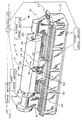
- Fig. 1 is perspective view of a programmable gravure engraver showing a headstock, a tailstock, an engraving head, and a plurality of cylinder supports;
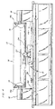
- Fig. 2 is a fragmentary front plan view of the engraver shown in Fig. 1, showing details of one of the telescoping cylinder supports;
- Fig. 3 is another plan view of the engraver showing the cylinder supported by the cylinder supports;
- Fig. 4 is another plan view of the engraver showing the cylinder rotatably supported by the headstock and tailstock after the cylinder supports have been retracted;
- Fig. 5 is a fragmentary sectional view showing details of the cylinder support and a support nest; and
- Fig. 6 is a top view of one of the cylinder supports, showing details of the support nest.
-
- Fig. 1 is a general perspective view of a preferred embodiment of an engraver, designated generally as
engraver 10. In the embodiment being described, theengraver 10 is a gravure engraver, but the invention may be suitable for use in any engraver. Theengraver 10 may have a surrounding slidable safety cabinet structure which is not shown for ease of illustration. Engraver 10 comprises abase 12 having aheadstock 16 andtailstock 18 slidably mounted intract 20 such that theheadstock 16 andtailstock 18 can move towards and away from each other. In this regard,engraver 10 comprises a plurality of linear actuators or first drive motor means orfirst drive motor 46 and a second drive motor means orsecond drive motor 48 which are capable of driving theheadstock 16 andtailstock 18, respectively, towards and away from each other. For example, the drive motors may cause theheadstock 16 andtailstock 18 to be actuated to a fully retracted position, as shown in Fig. 2, or to a cylinder support position shown in Fig. 1. The drive motors may be selectively energized to cause the headstock 154 andtailstock 18 to be actuated either independently or simultaneously. Although not shown, a single drive motor may be used with a single lead screw (not shown) having reverse threads (not shown) on which either end causes theheadstock 16 andtailstock 18 to move simultaneously towards and away from each other as the leadscrew is driven. Driving both theheadstock 16 andtailstock 18 permitscylinders 14 of varying lengths to be loaded by an overhead crane, for example, whose path is perpendicular to the engravers axis of rotation. However, it should be appreciated that astationary headstock 16 andtailstock 18 may be used with a driventailstock 16 orheadstock 18, respectively, if, for example, a cylinder loading mechanism (not shown) loads thecylinder 14 by moving it in a direction which is generally parallel to the axis of rotation of the engraver. As best illustrated in Figs. 2-4, theheadstock 16 andtailstock 18 comprise asupport shaft 16a andsupport shaft 18a, respectively. Thesupport shafts shaped end cylinder 14 comprises a first end 14a andsecond end 14b each having a receiving opening 19 (Fig. 2) for receivingends opening 19 is also conically shaped in cross-section so as to matingly receive theends - Although not shown, if a shafted cylinder (not shown) was to be engraved, then the
headstock 16 andtailstock 18 would each include a gripping device or chuck (not shown) to rotatably support the cylinder at theengraving station 15. - The
engraver 10 also comprises anengraving head 22 having a cutting tool or stylus (not shown) for engraving asurface 13 on thecylinder 14. In the embodiment being described,surface 13 preferably has a copper coating of the type used in gravure engraving. Theengraving head 22 is slidably mounted on acarriage 24 such that a third drive means orthird drive motor 21 can drive theengraving head 22 towards and away from thecylinder 14 in a direction which is generally radial with respect to the center axis ofcylinder 14. Thecarriage 24 is also slidably mounted onbase 12 such that it traverses theentire surface 13 ofcylinder 14 in the direction ofdouble arrow 26 in Fig. 1, which is generally parallel to the axis of thecylinder 14. Theengraver 10 also comprises a lead screw (not shown) and drive motors (not shown) for causing thecarriage 24 to move in the direction ofdouble arrow 26. Theengraving head 22,carriage 24 and transverse movement thereof is similar to that shown in Serial Nos. 08/038,679; 08/022,127; and 08/023,060 which is assigned to the same assignee as the present invention and which is incorporated herein by reference. - The engraver comprises a controller 17 which controls the operation of the
engraver 10 and which also controls all the drive motors, such asdrive motors drive motors engraver 10. - The
engraver 10 also comprises drive means or a drive motor 28 for rotatably driving thesupport member 16a,cylinder 14, andsupport member 18a. The drive motor 28 is operatively coupled to the programmable controller 17. - The
engraver 10 further comprises support means or at least one cylinder support 30 for supporting thecylinder 14 between theheadstock 16 andtailstock 18, for example, during loading and unloading. Thecylinder support 30 comprises asupport member 34 having a first end 34a conventionally secured tobase 12, for example, by a weld. Asecond end 34b ofsupport member 34 comprises asupport nest 36 which receives and supportscylinder 14. In the embodiment being described, thesupport member 30 is a telescoping support, with thesecond end 34b being capable of telescoping towards and away from said first end 34a. In this regard, eachcylinder support 30 also comprises drive means or adriver 32 which is coupled to controller 17 and which comprises a gear and screw assembly (not shown) for telescoping or driving the support nest 36 towards and away from theengraving station 15. As best illustrated in Fig. 2, the controller 17 can energizedriver 32 to move thecylinder support 30 into the support position shown in Fig. 2, whereupon thesupport nest 36 is capable of supporting thecylinder 14 atengraving station 15, for example, when thecylinder 14 is being loaded for engraving. As described later herein, the controller 17 subsequently energizesdriver 32 to retract thecylinder support 30 and support nest 36 to the retracted position shown in Fig. 4, for example, after thesupport shafts headstock 16 andtailstock 18, respectively, have engaged and support thecylinder 14. - As best shown in Figs. 5 and 6, the
support nest 36 comprises a plurality ofsupport arms 40 which rotatably support a plurality ofrollers rollers 38 are mounted in pairs on aroller assembly 45. Eachroller assembly 45 is pivotally mounted on an axle 43 (Fig. 5) which is coupled to one of thesupport arms 40. As best illustrated in Fig. 5, eachroller assembly 45 can pivot about the axis of itsrespective axle 43. Theroller assemblies 45 are each self-aligning and pivot to permit the engraver to accommodate a range of cylinder diameters. - The axis of each
roller 38 is generally perpendicular to the axis ofcylinder 14. This facilitates permitting thecylinder 14 to move laterally in theengraver 10 when theheadstock 16 andtailstock 18 grip and release thecylinder 14. The plurality ofrollers 38 also facilitate supportingcylinder 14 such that its center axis is generally parallel with the center axis of each of thesupport shafts headstock 16 andtailstock 18, respectively. - It is to be noted that
rollers 39 facilitate guiding and centeringcylinder 14 between theheadstock 16 andtailstock 18, thereby accommodating lateral misalignment when thecylinder 14 is loaded onto the engraver 10 from above. In the embodiment being described, the plurality ofrollers support nest 36 is capable of supportingcylinders 14 of various weights and having various lengths and diameters. - Although not shown, the
engraver 10 may include a plurality of brushes (not shown) positioned in operative relationship with therollers surface 13 ofcylinder 14. - The
engraver 10 also comprises sensing means orfirst sensors 42 which are coupled to controller 17 and which are located on the engraving head 22 (Fig. 1). The sensing means orsensors 42 are capable of sensing, for example, thesurface 13 ofcylinder 14. Thesensors 42 are also capable of sensing theends 14a and 14b ofcylinder 14. - The
engraver 10 also comprises second sensing means orsensors 44 coupled to controller 17 and associated with theheadstock 16 andtailstock 18 for detecting the proximate location of thecarriage 24 relative to theheadstock 16 andtailstock 18. In the embodiment being described the first andsecond sensors carriage 24 from engaging either theheadstock 16 or thetailstock 18. A method for loading and unloading thecylinder 14 on theengraver 10 will now be described. - When it is desired to load a
cylinder 14 onengraver 10, controller 17 energizes the first andsecond driver motors headstock 16 andtailstock 18, respectively, to move to the loading position shown in Fig. 2. It is to be noted that controller 17 can be programmed with dimensions of thecylinder 14, such as length and diameter. The controller 17 also energizesdriver 32 ofcylinder support 30 to telescope thesupport member 34 such that thesupport nest 36 is operatively positioned at theengraving station 15, as shown in Fig. 2. It is to be noted that controller 17, having been programmed with the length and diameter ofcylinder 14, energizesdriver 32 to position thesupport nest 36 such that, whencylinder 14 is supported by the cylinder supports 30, theends openings 19 on the first end 14a andsecond end 14b, respectively. After theheadstock 16 andtailstock 18 have been actuated to the open position shown in Fig. 2 and the cylinder supports 30 are in the support position, thecylinder 14 is lowered onto thesupport nest 36. As mentioned earlier herein, the plurality ofrollers 39 assist locating and centering thecylinder 14 on theroller assemblies 45 and theirrespective rollers 38. - Once the
cylinder 14 is supported by thesupport nests 36 of cylinder supports 30, the controller 17 can energize the first andsecond drivers support members ends 14a and 14b, respectively. Theheadstock 16 andtailstock 18 are driven towards cylinder ends 14a and 14b, respectively, until ends 16b and 18b matingly engage themating receiving openings 19 in theends 14a and 14b. Oncecylinder 14 is supported betweenends headstock 16 andtailstock 18, respectively, controller 17 energizes thedriver 32 to retract thesupport nest 36 to the non-support position shown in Fig. 4. It is to be noted that thecylinder 14 is rotatably supported between theheadstock 16 andtailstock 18 such that, when controller 17 energizes drive motor 28, thecylinder 14 rotates, for example, in a clockwise direction. The controller 17 subsequently energizes thethird drive motor 19 to move thecarriage 24 andengraving head 22, respectively, into operative relationship with thesurface 13 of thecylinder 14. It is to be noted that the controller 17 may usesensors cylinder 14 with respect to theengraving head 22. Thesensors ends 14a and 14b in order to facilitate preventingcarriage 24 from engaging either theheadstock 16 ortailstock 18. Thesensors engraving head 22 in the approximate center ofcylinder 14 which, in turn, enables theengraver 10 to accommodate for longitudinal variations incylinder 14 lengths after thecylinder 14 has been rotatably mounted in theengraver 10. This permits the image (not shown) to be engraved in thesurface 13 to be centered on thecylinder 14. Thesensors engraver 10 to set travel limits to prevent theengraving head 22 from engaging either theheadstock 16 ortailstock 18. - After the
cylinder 14 is properly located at theengraving station 15, the cylinder ends 14a and 14b are detected bysensors cylinder surface 13. The test pattern is typical cut at a location on thesurface 13 which will not be used by the image being engraved. - If the test pattern cut is unsatisfactory, then correction are made and another test pattern is cut. This process is repeated until a successful test pattern is cut. If the test pattern is acceptable, In the embodiment being described, controller 17 energizes drive motor 28 to rotatably drive
cylinder 14. Controller 17 then causes thecarriage 24 to cause theengraving head 22 to traverse thesurface 13 ofcylinder 14 and simultaneously energizes the cutting stylus (not shown) to oscillate into contact with thecylinder 14, thereby engraving the desired image which comprises a series of control depth cells (not shown) in thesurface 13 ofcylinder 14. Thecylinder 14 rotates in synchronism with the oscillating movement of the stylus (not shown) while the lead screw (not shown) arrangement provides axial movement of theengraving head 22 andcarriage 24 such that a precisely controlled engraving path (not shown) is maintained on thesurface 13 ofprint cylinder 14. - After engraving has been completed, controller 17 energizes
third drive motor 21 to retract theengraving head 22. Controller 17 also energizesdriver 32 to cause thecylinder support 30 to move into the support position shown in Figs. 1 and 2. Controller 17 then energizes the first andsecond drive motors headstock 16 andtailstock 18, respectively, as shown in Fig. 3. Thecylinder 14 may then be removed from theengraving station 15, and another cylinder may then be loaded and engraved in the manner described above. - Advantageously, this invention provides a method and apparatus for automatically loading an
engraver 10 with acylinder 14 to be engraved. The method and apparatus reduce or eliminate the need for an operator during loading and unloading ofcylinder 14. The invention may be used to fully automate the engraving process or, alternatively, the invention could be semi-automated, thereby permitting the operator to manually control the operation of theengraver 10. The method and apparatus also provide means for automatically loading and centeringcylinder 14 atengraving station 15 such that, for example, when theengraving head 22 is in the home position shown in Fig. 1, theengraving head 22 is positioned generally midway between ends 14a and 14b ofcylinder 14. - Various changes or modification in the invention described may occur to those skilled in the art without departing from the true spirit or scope of the invention. For example, although the invention has been shown and described as being pertinent to the gravure engraving environment, it should be appreciated that it could be used in other type of engraving, such as laser engraving of flexo rollers or other processes such as polishing of
cylinders 14. Also, theengraver 10 could be provided with onecylinder support 30 or a plurality of cylinder supports 30, if desired. Furthermore, thedriver 32 and first, second and third drive motor means 21, 46, and 48 have been described as comprising motors, but they could be any suitable driving apparatus which is capable of performing the same function. Likewise, the cylinder support or support means 30 has been shown and described as comprising thesupport member 34 andsupport nest 36, but it could comprise any suitable means which is capable of supporting thecylinder 14 at theengraving station 15 during loading and unloading.
Claims (16)
- An engraver (10) comprising:characterized in that the engraver further comprises:a base (12) having a headstock (16) an a tailstock (18) for rotatably supporting a cylinder (14) to be engraved therebetween; drive means (46, 48) coupled to at least one of said headstock (16) or tailstock (18) for driving the headstock and/or tailstock along said base (12) to engage and release the cylinder (14);a further drive motor (28) for rotatably driving said cylinder (14) when said cylinder is mounted between said headstock (16) and said tailstock (18);a carriage (24) slidably mounted on said base (12) to move in a direction which is generally parallel to the center axis of said cylinder (14);an engraving head (22) slildably mounted on said carriage (24) for movement towards and away from an engraving station (15) between said headstock and said tailstock;a third drive motor (21) causing said engraving head (22) to move toward and away from said engraving station (15); anda controller (17) coupled to said drive means (46, 48) said further drive motor (28), said support driver (32), and said third drive motor (21) for energizing said means and motors;at least one cylinder support (30) arranged between said headstock (16) and tailstock (18) for supporting the cylinder (14);a support driver (32) coupled to said at least one cylinder support (30) for driving said at least one cylinder support towards and away from said engraving station (15) and in a direction which is generally radial with respect to the center axis of the cylinder (14) when the cylinder is mounted between the headstock (16) and the tailstock (18); and further characterized in that said controller (17) is coupled to said support driver (32) for energizing said support driver to drive said at least one cylinder support (30) towards an away from said engraving station (15).
- The engraver according to claim 1, wherein said at least one cylinder support (30) comprises a support nest (36) at the upper end thereof for receiving and supporting said cylinder (14).
- The engraver according to claims 1 or 2, wherein said at least one cylinder support (30) comprises a telescoping support number (34) for raising and lowering said support (30).
- The engraver according to claim 3, wherein said support driver (32) comprises a gear and screw assembly for telescoping the support nest (36).
- The engraver according to claim 2, wherein said support nest (36) comprises a plurality of rollers (38, 39) for supporting said cylinder (14) between said headstock (16) and tailstock (18).
- The engraver according to claim 5, wherein said plurality of rollers (38, 39) are positioned in a general U-shape for receiving said cylinder to facilitate minimizing damage to the surface of the cylinder after the cylinder is supported by said plurality of rollers and when said cylinder moves in a direction which is generally parallel to the center axis of the cylinder.
- The engraver according to claim 5 or 6, wherein the support nest (36) comprises a plurality of support arms (40) carrying said rollers (38, 39), said rollers (38) are mounted in pairs on roller assemblies (45) each of which is pivotably mounted on an axle (43) of an associated support arm (40) such that the pivot axis of each roller (38) is perpendicular to the center axis of the cylinder (14).
- The engraver according to Claim 5, 6 or 7, wherein said rollers (38) and (39) are made of composite material.
- The engraver according to any one of the preceding claims 1 to 8, wherein the controller (17) is a programmable controller being programmable with the diameter of the cylinder (14) for positioning the upper end of the at least one cylinder support (30) in the support position for said cylinder at the engraving station (15) by said support driver (32) when energized by said controller (17).
- The engraver according to any one of the preceding claims 1 to 9, wherein said drive means comprisesa first drive motor (46) coupled to said headstock (16)a second drive motor (48) coupled to said tailstock (18)said first and second drive motors being capable ob being selectively energized to cause said headstock and tailstock to move towards and away from each other such that they can grip the respective ends (14a, 14b) of said cylinder (14).
- The engraver according to any one of the preceding claims I to 9, wherein said drive means comprises:a drive motor being coupled to both said headstock (16) and said tailstock (18);said drive motor being coupled to said headstock and tailstock such that said headstock and tailstock move towards and away from each other when said drive motor is enegized.
- The engraver according to any one of the preceding claims 1 to 9, wherein said drive means comprises;a drive motor coupled to either said headstock and said tailstock;said drive motor being coupled to either said headstock or said tailstock such that said headstock or tailstock moves towards and away from said tailstock and said headstock, respectively, when said drive motor is energized.
- The engraver according to any one of the preceding claims 1 to 9, wherein said engraver (10) is a gravure engraver.
- A method for supporting a cylinder (14) to be engraved in an engraver (10) having a base (12), a headstock (16) a tailstock (18), an engraving head (22), driving means (21, 28, 46, 48) and a controller (17), the latter energizing the driving means for moving the parts (16, 18, 22) into and away from an engraving position for said cylinder at an engraving station (15) between the headstock and the tailstock, said cylinder (14) being loaded on the engraver and being rotatably held by the headstock and the tailstock during engraving the surface (13) of said rotatably driven cylinder by the engraving head (22), said method being characterized by the steps of:driving the headstock (16) and the tailstock (18) to their loading positions away from the engraving station (15);raising at least one cylinder support (30) being arranged between the headstock and the tailstock and having a support nest (36) into the engraving station;loading said cylinder (14) on said support nest of said at least one cylinder support nest (36) at said engraving station (15) in the engraver (10);driving the headstock and the tailstock into the engraving station for rotatably supporting said cylinder between the headstock and the tailstock;lowering said at least one cylinder support (30) with said support nest (36) away from the said engraving station (15) for performing engraving of the surface (13) of said cylinder (14);said raising and lowering of said at least one cylinder support (30) being controlled by said controller (17) coupled to a driver (32) of said at least one cylinder support (30).
- The method according to claim 14, wherein, after engraving of the surface (13) of said cylinder (14) has been completed, said at least one cylinder support (30) is being raised into the engraving station (15) to engage said cylinder whereafter said headstock (16) and said tailstock (18) are being retracted from said cylinder such said the at least one cylinder support (30) supports said cylinder for its unloading.
- The method according to 14 or 15, wherein said driving means comprising a first drive motor (46) and a second drive motor (48), said first drive motor and said second drive motor are being energized to cause said headstock (16) and said tailstock (18), respectively, to move independently of one another or simultaneously towards and away from their loading positions.
Applications Claiming Priority (3)
| Application Number | Priority Date | Filing Date | Title |
|---|---|---|---|
| US08/057,327 US5424846A (en) | 1993-05-05 | 1993-05-05 | Cylinder support apparatus and method for use in an engraver |
| PCT/US1994/005133 WO1994026060A1 (en) | 1993-05-05 | 1994-05-04 | Engraver cylinder support apparatus and method |
| US57327 | 1997-09-02 |
Publications (3)
| Publication Number | Publication Date |
|---|---|
| EP0697156A1 EP0697156A1 (en) | 1996-02-21 |
| EP0697156A4 EP0697156A4 (en) | 1998-09-16 |
| EP0697156B1 true EP0697156B1 (en) | 2002-08-21 |
Family
ID=22009912
Family Applications (1)
| Application Number | Title | Priority Date | Filing Date |
|---|---|---|---|
| EP94916059A Expired - Lifetime EP0697156B1 (en) | 1993-05-05 | 1994-05-04 | Engraver cylinder support apparatus and method |
Country Status (10)
| Country | Link |
|---|---|
| US (2) | US5424846A (en) |
| EP (1) | EP0697156B1 (en) |
| JP (1) | JP3449719B2 (en) |
| CN (1) | CN1123201C (en) |
| AT (1) | ATE222676T1 (en) |
| BR (1) | BR9406341A (en) |
| DE (1) | DE69431202T2 (en) |
| ES (1) | ES2181718T3 (en) |
| RU (2) | RU2120385C1 (en) |
| WO (1) | WO1994026060A1 (en) |
Families Citing this family (46)
| Publication number | Priority date | Publication date | Assignee | Title |
|---|---|---|---|---|
| US5663803A (en) * | 1993-02-25 | 1997-09-02 | Ohio Electronic Engravers, Inc. | Engraving method and apparatus for engraving areas using a shaping signal |
| US5583647A (en) * | 1993-05-05 | 1996-12-10 | Ohio Electronic Engravers, Inc. | Cylinder support apparatus and method for use in an engraver |
| US5424846A (en) * | 1993-05-05 | 1995-06-13 | Ohio Electronic Engravers, Inc. | Cylinder support apparatus and method for use in an engraver |
| US5661565A (en) * | 1993-05-05 | 1997-08-26 | Ohio Electronic Engravers, Inc. | Method and apparatus for aligning a cylinder in an engraver |
| JPH08276556A (en) * | 1995-04-04 | 1996-10-22 | Dainippon Screen Mfg Co Ltd | Gravure plate making apparatus |
| DE19627746C2 (en) * | 1995-07-14 | 2002-12-12 | Dainippon Screen Mfg | Gravure engraving system |
| JP3474970B2 (en) | 1995-07-14 | 2003-12-08 | 大日本スクリーン製造株式会社 | Gravure engraving system |
| US5652659A (en) * | 1995-10-09 | 1997-07-29 | Ohio Electronic Engravers, Inc. | System and method for measuring run-out and other characteristics of a workpiece mounted on an engraver |
| US5819658A (en) * | 1996-10-30 | 1998-10-13 | Ohio Electronic Engravers, Inc. | Engraver having universal cylinder mount |
| US5751436A (en) * | 1996-12-23 | 1998-05-12 | Rocky Mountain Instrument Company | Method and apparatus for cylindrical coordinate laser engraving |
| DE19710447C2 (en) * | 1997-03-13 | 1999-01-14 | Bernhard Magerl | Device for feeding the workpiece into a clamping area of a machine tool |
| US5947020A (en) * | 1997-12-05 | 1999-09-07 | Ohio Electronic Engravers, Inc. | System and method for engraving a plurality of engraved areas defining different screens |
| DE19921138C2 (en) * | 1999-05-07 | 2003-12-24 | Hell Gravure Systems Gmbh | Method and device for loading printing cylinders |
| RU2169670C1 (en) * | 2000-12-19 | 2001-06-27 | Государственное предприятие "Московский монетный двор" | Method for machine engraving of image on metal |
| GB2426742A (en) * | 2005-04-29 | 2006-12-06 | Luscher Zed Flexo Ltd | Engraving cylinder end assembly |
| DE102006060464C5 (en) * | 2006-12-19 | 2013-12-24 | Bobst Bielefeld Gmbh | Method of adjusting a roll in a rotary printing machine |
| EP1916102B2 (en) † | 2006-10-23 | 2014-06-25 | Bobst Bielefeld GmbH | Method of adjusting a roller in a rotary printing press |
| CN101036960B (en) * | 2007-04-26 | 2011-06-15 | 瑞安市博业激光应用技术有限公司 | Rotating device for laser carving |
| US7715058B2 (en) * | 2007-05-18 | 2010-05-11 | Daetwyler R & D Corp. | System and method for improved engraving of gravure cylinders by adjusting engraving signal responsive to movement of shoe position |
| CL2008002961A1 (en) * | 2007-10-04 | 2009-05-08 | Bio Arch Lab Inc | Method for converting an appropriate monosaccharide or oligosaccharide into a generic chemical comprising contacting said molecules with a microbial system comprising one or more genes that encode and express a biosynthesis pathway. |
| CN102336049B (en) * | 2010-07-15 | 2015-01-21 | 常州精华数控设备有限公司 | Balancing unit for roll carving machine |
| CN102343705B (en) * | 2010-08-06 | 2014-06-25 | 上海运安制版有限公司 | Laser engraving processing method and device for ultra-soft printing roller |
| CN102398044B (en) * | 2010-09-17 | 2013-08-07 | 上海重型机床厂有限公司 | Automatic processing equipment and method for slender axle part |
| CN102266971A (en) * | 2011-07-15 | 2011-12-07 | 伍建秀 | High-speed numerical control roller carving-milling machine and method for carving-milling workpiece |
| CN102294493A (en) * | 2011-08-25 | 2011-12-28 | 成都科盛石油科技有限公司 | Separating flexible double-head spire used for lathe processing |
| US9199443B2 (en) | 2011-12-07 | 2015-12-01 | Think Laboratory Co., Ltd. | Single motor-driven gravure cylinder chuck mechanism |
| CN102602206B (en) * | 2012-02-27 | 2014-01-29 | 常州士林电机有限公司 | Transfer making machine |
| CN103526500A (en) * | 2013-09-06 | 2014-01-22 | 武汉金运激光股份有限公司 | Three-dimensional jean laser-carving machine and using method thereof |
| CN103843614A (en) * | 2014-03-24 | 2014-06-11 | 刘自学 | Stone pattern flowerpot, manufacturing method and vertical and horizontal embossing machine for manufacturing stone pattern flowerpot |
| CN104117690B (en) * | 2014-07-23 | 2016-06-01 | 汤阴县华北工业塑料装备有限公司 | A kind of carrying roller radial run-out processing special purpose lathe equipment |
| CN104748340B (en) * | 2015-03-31 | 2018-09-11 | 广东美的制冷设备有限公司 | Wind guiding mechanism and air conditioner with it |
| CN105128581A (en) * | 2015-07-01 | 2015-12-09 | 郭斌 | Rotary clamp assembly of delicate furniture engraving machine |
| US10022801B1 (en) * | 2015-12-01 | 2018-07-17 | Gregory Devaney | Pipe bracing device for pipe machining apparatus |
| CN105437843B (en) * | 2015-12-22 | 2019-06-25 | 东莞市瑞必达科技股份有限公司 | A kind of handling equipment of engraving machine |
| CN107877587A (en) * | 2017-12-15 | 2018-04-06 | 绍兴厚道自动化设备有限公司 | A kind of composite band cutter device for being easy to regulation cutting size |
| CN110001259B (en) * | 2019-04-23 | 2020-07-24 | 北京天图天美创意文化有限公司 | Clamp of engraving machine for flat workpieces |
| CN110901272B (en) * | 2019-12-05 | 2021-04-23 | 浙江广厦建设职业技术学院 | Multi-angle three-dimensional carving machine |
| CN110980252B (en) * | 2019-12-26 | 2021-08-17 | 浙江众邦新型金属材料有限公司 | Disc rotary type board opening and containing device |
| CN111722584B (en) * | 2020-05-28 | 2021-11-05 | 固高科技股份有限公司 | Fast knife servo system, electric engraving system and electric engraving control method |
| CN112223469A (en) * | 2020-10-14 | 2021-01-15 | 赵绕贵 | Wood raw material clamping and rotating mechanism |
| US11628529B2 (en) * | 2020-11-04 | 2023-04-18 | Tong Li | Engraving fixture for multiple serially arranged objects |
| CN112872604B (en) * | 2021-02-01 | 2022-07-26 | 运城制版有限公司 | Intelligent intaglio roller engraving system based on Internet of things |
| CN114161160B (en) * | 2022-01-04 | 2022-12-13 | 浙江蓝箭航天空间科技有限公司 | Large-size cylinder anti-deformation longitudinal joint milling and welding support device |
| BR102022011135A2 (en) * | 2022-06-07 | 2023-12-19 | Petróleo Brasileiro S.A. - Petrobras | STATIONARY CUTTING MACHINE AND METHODS OF CUTTING AND WITHDRAWING THE PIPE PRESERVATION SYSTEM |
| EP4431210A1 (en) * | 2023-03-16 | 2024-09-18 | Grob-Werke GmbH & Co. KG | Identification and reading method, machining method, machining machine and production line to be carried out by means of a machining machine |
| US20250178100A1 (en) * | 2023-11-30 | 2025-06-05 | Gary Craft | Work material stabilizer for a lathe |
Family Cites Families (30)
| Publication number | Priority date | Publication date | Assignee | Title |
|---|---|---|---|---|
| US1815105A (en) * | 1930-06-20 | 1931-07-21 | Howey Walter | Cylindrical scanning |
| US2493628A (en) * | 1945-12-15 | 1950-01-03 | Earle L Harley | Optical means for registering printing surfaces |
| US2769199A (en) * | 1952-07-01 | 1956-11-06 | Fairchild Camera Instr Co | Engraving stylus |
| US2874479A (en) * | 1955-07-15 | 1959-02-24 | Fairchild Camera Instr Co | Engraving machine stylus index |
| US2881246A (en) * | 1955-09-27 | 1959-04-07 | Fairchild Camera Instr Co | Engraving machine |
| DE1588313A1 (en) * | 1967-12-06 | 1970-12-10 | Hell Rudolf Dr Ing Fa | Method for driving drum printing machines |
| US3544713A (en) * | 1968-09-03 | 1970-12-01 | Marquardt Corp | Solid state electro-optical contact scanner |
| US3838258A (en) * | 1970-02-10 | 1974-09-24 | Gerber Scientific Instr Co | Step motor control system |
| US3694570A (en) * | 1970-07-22 | 1972-09-26 | Evgeny Pavlovich Kotov | Automatic engraving machine |
| US3770888A (en) * | 1971-10-04 | 1973-11-06 | Werkspoor Amsterdam Nv | Method and apparatus for controlling the engraving pattern of an electromagnetic gravure engraving |
| CH579985A5 (en) * | 1973-07-16 | 1976-09-30 | Hell Rudolf Dr Ing Gmbh | |
| US3949159A (en) * | 1973-11-11 | 1976-04-06 | American Newspaper Publishers Association | Composite page setter |
| US3990133A (en) * | 1974-01-15 | 1976-11-09 | Gildemeister Aktiengesellschaft | Multi-station machine tool with pairs of tool-and work-spindles |
| NL167897C (en) * | 1975-02-28 | 1982-02-16 | Hell Rudolf Dr Ing Gmbh | APPARATUS FOR MANUFACTURING GRID PRINTING ACCORDING TO AN IMAGE ORIGINAL. |
| DE2513042C3 (en) * | 1975-03-25 | 1981-07-30 | Dr.-Ing. Rudolf Hell Gmbh, 2300 Kiel | Method for the precise setting of the start and end of the reproduction |
| US4003311A (en) * | 1975-08-13 | 1977-01-18 | Bardin Karl D | Gravure printing method |
| US4054081A (en) * | 1975-11-20 | 1977-10-18 | Aluminum Company Of America | Machining method |
| US4054745A (en) * | 1976-12-06 | 1977-10-18 | Gte Automatic Electric (Canada) Limited | Motor control device for data terminals |
| US4450486A (en) * | 1979-07-11 | 1984-05-22 | Ohio Electronic Engravers, Inc. | Engraving apparatus and method |
| US4357633A (en) * | 1979-07-11 | 1982-11-02 | Buechler Lester W | Engraving apparatus and method |
| US4451856A (en) * | 1979-07-11 | 1984-05-29 | Ohio Electronic Engravers, Inc. | Engraving and scanning apparatus |
| DE3114529A1 (en) * | 1981-04-10 | 1982-12-02 | Franz 4060 Viersen Csernak | Device for producing gravure printing formes on a plate |
| WO1984005006A1 (en) * | 1983-06-03 | 1984-12-20 | Gravure Res Inst | Screen gravure engraving system for electromechanical engravers |
| DE3440039A1 (en) * | 1984-11-02 | 1986-05-07 | Dr.-Ing. Rudolf Hell Gmbh, 2300 Kiel | DEVICE FOR SUPPORTING SPINDLES |
| SU1404370A1 (en) * | 1986-07-08 | 1988-06-23 | Предприятие П/Я М-5343 | Electronic engraving machine |
| DE3809619A1 (en) * | 1988-03-22 | 1989-10-12 | Boehringer Werkzeugmaschinen | METHOD AND DEVICE FOR MACHINING ROTATIONALLY SYMMETRIC COMPONENTS |
| US5029011A (en) * | 1990-04-13 | 1991-07-02 | Ohio Electronic Engravers, Inc. | Engraving apparatus with oscillatory movement of tool support shaft monitored and controlled to reduce drift and vibration |
| US5492057A (en) * | 1994-05-12 | 1996-02-20 | Ohio Electronic Engravers, Inc. | Method and apparatus for positioning at least one engraving head |
| US5424846A (en) * | 1993-05-05 | 1995-06-13 | Ohio Electronic Engravers, Inc. | Cylinder support apparatus and method for use in an engraver |
| US5583647A (en) * | 1993-05-05 | 1996-12-10 | Ohio Electronic Engravers, Inc. | Cylinder support apparatus and method for use in an engraver |
-
1993
- 1993-05-05 US US08/057,327 patent/US5424846A/en not_active Expired - Lifetime
-
1994
- 1994-05-04 ES ES94916059T patent/ES2181718T3/en not_active Expired - Lifetime
- 1994-05-04 AT AT94916059T patent/ATE222676T1/en not_active IP Right Cessation
- 1994-05-04 RU RU95122241A patent/RU2120385C1/en active
- 1994-05-04 BR BR9406341A patent/BR9406341A/en unknown
- 1994-05-04 EP EP94916059A patent/EP0697156B1/en not_active Expired - Lifetime
- 1994-05-04 DE DE69431202T patent/DE69431202T2/en not_active Expired - Fee Related
- 1994-05-04 JP JP52467394A patent/JP3449719B2/en not_active Expired - Fee Related
- 1994-05-04 CN CN94192004.6A patent/CN1123201C/en not_active Expired - Fee Related
- 1994-05-04 WO PCT/US1994/005133 patent/WO1994026060A1/en not_active Ceased
- 1994-05-04 RU RU97108674A patent/RU2123939C1/en active
-
1995
- 1995-06-07 US US08/480,919 patent/US5751435A/en not_active Expired - Fee Related
Also Published As
| Publication number | Publication date |
|---|---|
| WO1994026060A1 (en) | 1994-11-10 |
| BR9406341A (en) | 1995-12-26 |
| CN1122641A (en) | 1996-05-15 |
| US5424846A (en) | 1995-06-13 |
| EP0697156A4 (en) | 1998-09-16 |
| DE69431202D1 (en) | 2002-09-26 |
| RU2120385C1 (en) | 1998-10-20 |
| JPH08510178A (en) | 1996-10-29 |
| ATE222676T1 (en) | 2002-09-15 |
| RU2123939C1 (en) | 1998-12-27 |
| ES2181718T3 (en) | 2003-03-01 |
| DE69431202T2 (en) | 2002-12-05 |
| US5751435A (en) | 1998-05-12 |
| EP0697156A1 (en) | 1996-02-21 |
| CN1123201C (en) | 2003-10-01 |
| JP3449719B2 (en) | 2003-09-22 |
Similar Documents
| Publication | Publication Date | Title |
|---|---|---|
| US5424846A (en) | Cylinder support apparatus and method for use in an engraver | |
| US5715068A (en) | System and method for automated loading, unloading and registration of a cylinder in an engraver | |
| US5074212A (en) | Automatic printing plate attaching system | |
| JP2825444B2 (en) | Printing machine having at least one plate cylinder with a replaceable sleeve containing a printing plate | |
| US5492057A (en) | Method and apparatus for positioning at least one engraving head | |
| EP1952938B1 (en) | Workpiece machining apparatus with a plurality of workpiece support devices | |
| US5867280A (en) | Engraver with automatic tool changer | |
| US5652659A (en) | System and method for measuring run-out and other characteristics of a workpiece mounted on an engraver | |
| US5475914A (en) | Engraving head with cartridge mounted components | |
| DE69404552T2 (en) | Device for scraping tires, with adjustable relative positioning of the tire and the tool | |
| CA2252500C (en) | Printing plate mounting structure | |
| JPH06500740A (en) | Automated workpiece handling system used in machine tools | |
| KR102682337B1 (en) | High-speed transfer printing system for pallets with fork insertion port | |
| WO2024074397A1 (en) | Anilox roll cleaning equipment | |
| JP4505079B2 (en) | Roller table with work set function | |
| CN112404742A (en) | Automatic laser engraving machine for glassware | |
| CN220388265U (en) | Feeding mechanism of laser engraving machine | |
| CN219617246U (en) | Deviation-preventing feeding butt joint mechanism of false tooth engraving machine | |
| KR100217243B1 (en) | CNC lathe loading device | |
| JPH06126939A (en) | Plate cylinder positioning device of printing press | |
| JP2556793B2 (en) | Automatic pallet changer for jig on broaching machine | |
| KR100942371B1 (en) | Workpiece phase control | |
| CN119387909A (en) | Automatic positioning punching device | |
| CN119657961A (en) | Processing technology convenient for die casting information tracing | |
| JPH0699349A (en) | Polishing method and device thereof |
Legal Events
| Date | Code | Title | Description |
|---|---|---|---|
| PUAI | Public reference made under article 153(3) epc to a published international application that has entered the european phase |
Free format text: ORIGINAL CODE: 0009012 |
|
| 17P | Request for examination filed |
Effective date: 19951030 |
|
| AK | Designated contracting states |
Kind code of ref document: A1 Designated state(s): AT BE CH DE DK ES FR GB GR IE IT LI LU MC NL PT SE |
|
| A4 | Supplementary search report drawn up and despatched | ||
| AK | Designated contracting states |
Kind code of ref document: A4 Designated state(s): AT BE CH DE DK ES FR GB GR IE IT LI LU MC NL PT SE |
|
| 17Q | First examination report despatched |
Effective date: 19991201 |
|
| RAP1 | Party data changed (applicant data changed or rights of an application transferred) |
Owner name: MDC MAX DAETWYLER AG BLEIENBACH |
|
| GRAG | Despatch of communication of intention to grant |
Free format text: ORIGINAL CODE: EPIDOS AGRA |
|
| GRAG | Despatch of communication of intention to grant |
Free format text: ORIGINAL CODE: EPIDOS AGRA |
|
| GRAH | Despatch of communication of intention to grant a patent |
Free format text: ORIGINAL CODE: EPIDOS IGRA |
|
| GRAH | Despatch of communication of intention to grant a patent |
Free format text: ORIGINAL CODE: EPIDOS IGRA |
|
| GRAA | (expected) grant |
Free format text: ORIGINAL CODE: 0009210 |
|
| AK | Designated contracting states |
Kind code of ref document: B1 Designated state(s): AT BE CH DE DK ES FR GB GR IE IT LI LU MC NL PT SE |
|
| PG25 | Lapsed in a contracting state [announced via postgrant information from national office to epo] |
Ref country code: NL Free format text: LAPSE BECAUSE OF FAILURE TO SUBMIT A TRANSLATION OF THE DESCRIPTION OR TO PAY THE FEE WITHIN THE PRESCRIBED TIME-LIMIT Effective date: 20020821 Ref country code: LI Free format text: LAPSE BECAUSE OF THE APPLICANT RENOUNCES Effective date: 20020821 Ref country code: GR Free format text: LAPSE BECAUSE OF FAILURE TO SUBMIT A TRANSLATION OF THE DESCRIPTION OR TO PAY THE FEE WITHIN THE PRESCRIBED TIME-LIMIT Effective date: 20020821 Ref country code: CH Free format text: LAPSE BECAUSE OF THE APPLICANT RENOUNCES Effective date: 20020821 Ref country code: BE Free format text: LAPSE BECAUSE OF FAILURE TO SUBMIT A TRANSLATION OF THE DESCRIPTION OR TO PAY THE FEE WITHIN THE PRESCRIBED TIME-LIMIT Effective date: 20020821 Ref country code: AT Free format text: LAPSE BECAUSE OF FAILURE TO SUBMIT A TRANSLATION OF THE DESCRIPTION OR TO PAY THE FEE WITHIN THE PRESCRIBED TIME-LIMIT Effective date: 20020821 |
|
| REF | Corresponds to: |
Ref document number: 222676 Country of ref document: AT Date of ref document: 20020915 Kind code of ref document: T |
|
| REG | Reference to a national code |
Ref country code: GB Ref legal event code: FG4D |
|
| REG | Reference to a national code |
Ref country code: CH Ref legal event code: NV Representative=s name: KELLER & PARTNER PATENTANWAELTE AG Ref country code: CH Ref legal event code: EP |
|
| REF | Corresponds to: |
Ref document number: 69431202 Country of ref document: DE Date of ref document: 20020926 |
|
| REG | Reference to a national code |
Ref country code: IE Ref legal event code: FG4D |
|
| PG25 | Lapsed in a contracting state [announced via postgrant information from national office to epo] |
Ref country code: SE Free format text: LAPSE BECAUSE OF FAILURE TO SUBMIT A TRANSLATION OF THE DESCRIPTION OR TO PAY THE FEE WITHIN THE PRESCRIBED TIME-LIMIT Effective date: 20021121 Ref country code: DK Free format text: LAPSE BECAUSE OF FAILURE TO SUBMIT A TRANSLATION OF THE DESCRIPTION OR TO PAY THE FEE WITHIN THE PRESCRIBED TIME-LIMIT Effective date: 20021121 |
|
| PG25 | Lapsed in a contracting state [announced via postgrant information from national office to epo] |
Ref country code: PT Free format text: LAPSE BECAUSE OF FAILURE TO SUBMIT A TRANSLATION OF THE DESCRIPTION OR TO PAY THE FEE WITHIN THE PRESCRIBED TIME-LIMIT Effective date: 20021204 |
|
| NLV1 | Nl: lapsed or annulled due to failure to fulfill the requirements of art. 29p and 29m of the patents act | ||
| ET | Fr: translation filed | ||
| REG | Reference to a national code |
Ref country code: ES Ref legal event code: FG2A Ref document number: 2181718 Country of ref document: ES Kind code of ref document: T3 |
|
| PGFP | Annual fee paid to national office [announced via postgrant information from national office to epo] |
Ref country code: GB Payment date: 20030417 Year of fee payment: 10 |
|
| PGFP | Annual fee paid to national office [announced via postgrant information from national office to epo] |
Ref country code: FR Payment date: 20030429 Year of fee payment: 10 |
|
| PG25 | Lapsed in a contracting state [announced via postgrant information from national office to epo] |
Ref country code: LU Free format text: LAPSE BECAUSE OF NON-PAYMENT OF DUE FEES Effective date: 20030504 |
|
| PG25 | Lapsed in a contracting state [announced via postgrant information from national office to epo] |
Ref country code: IE Free format text: LAPSE BECAUSE OF NON-PAYMENT OF DUE FEES Effective date: 20030505 Ref country code: ES Free format text: LAPSE BECAUSE OF NON-PAYMENT OF DUE FEES Effective date: 20030505 |
|
| PG25 | Lapsed in a contracting state [announced via postgrant information from national office to epo] |
Ref country code: MC Free format text: LAPSE BECAUSE OF NON-PAYMENT OF DUE FEES Effective date: 20030531 |
|
| REG | Reference to a national code |
Ref country code: CH Ref legal event code: PL |
|
| PLBE | No opposition filed within time limit |
Free format text: ORIGINAL CODE: 0009261 |
|
| STAA | Information on the status of an ep patent application or granted ep patent |
Free format text: STATUS: NO OPPOSITION FILED WITHIN TIME LIMIT |
|
| 26N | No opposition filed |
Effective date: 20030522 |
|
| REG | Reference to a national code |
Ref country code: IE Ref legal event code: MM4A |
|
| PG25 | Lapsed in a contracting state [announced via postgrant information from national office to epo] |
Ref country code: GB Free format text: LAPSE BECAUSE OF NON-PAYMENT OF DUE FEES Effective date: 20040504 |
|
| REG | Reference to a national code |
Ref country code: ES Ref legal event code: FD2A Effective date: 20030505 |
|
| GBPC | Gb: european patent ceased through non-payment of renewal fee |
Effective date: 20040504 |
|
| PG25 | Lapsed in a contracting state [announced via postgrant information from national office to epo] |
Ref country code: FR Free format text: LAPSE BECAUSE OF NON-PAYMENT OF DUE FEES Effective date: 20050131 |
|
| REG | Reference to a national code |
Ref country code: FR Ref legal event code: ST |
|
| PG25 | Lapsed in a contracting state [announced via postgrant information from national office to epo] |
Ref country code: IT Free format text: LAPSE BECAUSE OF NON-PAYMENT OF DUE FEES Effective date: 20050504 |
|
| PGFP | Annual fee paid to national office [announced via postgrant information from national office to epo] |
Ref country code: DE Payment date: 20080528 Year of fee payment: 15 |
|
| PG25 | Lapsed in a contracting state [announced via postgrant information from national office to epo] |
Ref country code: DE Free format text: LAPSE BECAUSE OF NON-PAYMENT OF DUE FEES Effective date: 20091201 |