EP0696484A2 - Mail separating device - Google Patents
Mail separating device Download PDFInfo
- Publication number
- EP0696484A2 EP0696484A2 EP95112514A EP95112514A EP0696484A2 EP 0696484 A2 EP0696484 A2 EP 0696484A2 EP 95112514 A EP95112514 A EP 95112514A EP 95112514 A EP95112514 A EP 95112514A EP 0696484 A2 EP0696484 A2 EP 0696484A2
- Authority
- EP
- European Patent Office
- Prior art keywords
- channel
- item
- stop
- items
- Prior art date
- Legal status (The legal status is an assumption and is not a legal conclusion. Google has not performed a legal analysis and makes no representation as to the accuracy of the status listed.)
- Withdrawn
Links
Images

Classifications
-
- B—PERFORMING OPERATIONS; TRANSPORTING
- B07—SEPARATING SOLIDS FROM SOLIDS; SORTING
- B07C—POSTAL SORTING; SORTING INDIVIDUAL ARTICLES, OR BULK MATERIAL FIT TO BE SORTED PIECE-MEAL, e.g. BY PICKING
- B07C1/00—Measures preceding sorting according to destination
- B07C1/02—Forming articles into a stream; Arranging articles in a stream, e.g. spacing, orientating
- B07C1/04—Forming a stream from a bulk; Controlling the stream, e.g. spacing the articles
Definitions
- the present invention relates to a mail separating device.
- Mail sorting devices which provide for withdrawing flat rectangular mail items one at a time from a stack of superimposed items, and for feeding the items to a conveyor channel along which they travel separately.
- European Patent Application EP-A-582.869 by FINMECCANICA S.p.A. relates to a sorting device comprising an inclined rectangular surface for supporting a stack of mail items, which is pushed by a slide along the inclined surface to a stop device fitted to the upper end edge of the surface.
- the sorting device also comprises a gripping head movable in crank and slotted link manner to and from the inclined surface, and which provides for withdrawing the mail items one at a time from the stack and feeding them to the conveyor channel. More specifically, the gripping head conveniently comprises a number of suction cups which engage the front surface of the item contacting the stop device.
- pairs of adjacent, superimposed items may inadvertently be withdrawn (multiple withdrawal) and fed as such to the conveyor channel.
- a mail separating device characterized in that it comprises:
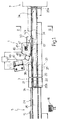
- Number 1 in Figure 1 indicates a mail separating device located along a straight conveyor channel 3 extending between a known sorting device 5 (shown partly and schematically in Figure 1) and an unloading device 7 (also shown schematically).
- Sorting device 5 may, for example, be of the type described in European Patent Application EP-A-582.869 by FINMECCANICA S.p.A., and may comprise ( Figure 4) an inclined rectangular surface 10 for supporting a stack 11 of flat rectangular mail items 12 (letters, envelopes, magazines, newspapers, etc.) which is pushed by a slide 13 along inclined surface 10 to a stop device 14 fitted to the upper end edge 15 of surface 10.
- Sorting device 5 also comprises a gripping head 16 movable in crank and slotted link manner to and from inclined surface 10, and for withdrawing mail items 12 one at a time from stack 11, and feeding them to conveyor channel 3. More specifically, gripping head 16 conveniently comprises a number of suction cups for engaging the front surface 12' of the item 12 contacting stop device 14.
- pairs of adjacent, superimposed items 12a, 12b may inadvertently be withdrawn and fed as such to conveyor channel 3.
- Separating device 1 provides for detecting and separating such pairs of items 12a, 12b.
- straight channel 3 presents a rectangular cross section, and comprises a rectangular bottom wall 20; and two rectangular lateral walls 21, 22 cooperating with sheets 28, 29 of undulated synthetic material extending inside and along the full length of channel 3, for enabling smooth slide of items 12 along the channel.
- Bottom wall 20 extends from an end edge 20a (corresponding to output 3a of channel 3) adjacent to unloading device 7, to an end edge 20b (corresponding to input 3b of channel 3) adjacent to the output of a conveyor belt device 24 of sorting device 5. More specifically, conveyor belt device 24 comprises a straight horizontal belt 26 parallel to and beneath end edge 15, and which provides for feeding the mail items released on to it by gripping head 16 towards edge 20b.
- Conveyor channel 3 comprises a number of known pinch roller devices 33 located along walls 21, 22 and which provide for moving items 12 along channel 3.
- Each pinch roller device 33 comprises a first powered roller 36 fitted to wall 21; and a second powered roller 37 located close to a rectangular opening (not shown) in wall 22, and which is movable between an idle position wherein it is clear of channel 3, and an activating position wherein it engages the opening and roller 36.
- Rollers 36, 37 provide for engaging opposite bottom surfaces of item 12 inside channel 3, and in particular for rapidly accelerating item 12.
- Conveyor channel 3 also comprises a bottom conveyor belt 34 parallel to bottom wall 20, and which extends from input 3b to output 3a of channel 3, and is moved from sorting device 5 to unloading device 7 by actuating means (not shown).
- separating device 1 comprises a stop assembly 40 substantially halfway along channel 3; and a laser sensor 42 located between input 3b of channel 3 and stop assembly 40.
- Sensor 42 comprises a photoemitting device (not shown), and a photoreceiving device (not shown) for receiving the light reflected and diffused by items 12.
- the photoemitting and photoreceiving devices (not shown) are positioned facing the channel, and define respective optical paths L, T extending through a hole F ( Figure 1) in wall 21, and forming an angle of roughly 80° with channel 3.
- Sensor 42 cooperates with an electronic unit 43 for receiving, and detecting rapid variations in, the electric signal generated by the photoreceiving device (not shown), which rapid variations correspond to discontinuity of item 12, as explained in more detail later on.
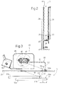
- Stop assembly 40 comprises a cylindrical electromagnetic actuator 45 fitted to a rectangular metal bracket 46 extending perpendicularly from wall 21 and outwards of channel 3; and actuator 45 presents an output shaft 47 parallel to walls 21, 22 and supporting an L-shaped plate 50. More specifically (Figure 3), plate 50 comprises a first straight portion 51 with a first end 51a fitted to shaft 47; and a second straight portion 52 perpendicular to and shorter than portion 51, and presenting a rounded end 52a with a reflecting surface 54, the function of which is explained later on.
- Plate 50 engages an elongated rectangular opening 58 ( Figure 3) in wall 21, and is movable by actuator 45 between an idle position (shown by the continuous line in Figures 1 and 3) wherein portion 51 is parallel to wall 21, and rounded end 52a projects slightly from wall 21 into channel 3, and an activating position (shown by the dotted line) wherein portion 51 is inclined in relation to wall 21, and portion 52 engages opening 58 and penetrates inside channel 3 with rounded portion 52a positioned substantially halfway across the channel.
- Stop device 40 also presents a sensor 60 (conveniently comprising a photocell) fitted to bracket 46 and defining an optical path 61 extending through wall 21 (through an opening shown in Figure 3) and which intersects rounded portion 52a when plate 50 is in the activating position.
- a sensor 60 (conveniently comprising a photocell) fitted to bracket 46 and defining an optical path 61 extending through wall 21 (through an opening shown in Figure 3) and which intersects rounded portion 52a when plate 50 is in the activating position.
- mail items 12 are withdrawn by gripping head 16 from pack 11 and released on to conveyor belt device 24 by which they are fed to conveyor channel 3 where they continue moving in known manner by means of conveyor belt 34 and pinch rollers 33 which close to engage bottom portions of items 12. In this way, items 12 travel from input 3b to output 3a of channel 3 at a speed of roughly 2.7-3 meters/second.
- a first item e.g. 12a
- a vertical end edge E1 separated by length L (of at least 10 millimeters) from the corresponding vertical end edge E2 of the other item (e.g. 12b).
- End edge E2 of item 12b defines, on the flat surface 12a' of item 12a, a step-shaped discontinuity which reflects light differently from the flat surfaces adjacent to it, and which is detected (in known manner) by unit 43 via sensor 42.
- electromagnetic actuator 45 is activated to rapidly move plate 50 from the idle to the activating position, so that end 52a of portion 52 contacts the exposed portion of surface 12a' and hence end edge E2 of item 12b.
- portion 52a on edge E2 stops item 12b, whereas item 12a continues moving along channel 3 either by inertia or conveyed by bottom conveyor belt 34, so that items 12a, 12b are detached from each other.
- electromagnetic actuator 45 is again activated to rapidly move plate 50 from the activating to the idle position.
- item 12b is detached from plate 50 and is once more fed along channel 3 by bottom conveyor belt 34.
- Separating device 1 thus provides for detecting multiple withdrawals and separating the items withdrawn simultaneously.
Abstract

Description
- The present invention relates to a mail separating device.
- Mail sorting devices are known which provide for withdrawing flat rectangular mail items one at a time from a stack of superimposed items, and for feeding the items to a conveyor channel along which they travel separately.
- European Patent Application EP-A-582.869 by FINMECCANICA S.p.A., for example, relates to a sorting device comprising an inclined rectangular surface for supporting a stack of mail items, which is pushed by a slide along the inclined surface to a stop device fitted to the upper end edge of the surface. The sorting device also comprises a gripping head movable in crank and slotted link manner to and from the inclined surface, and which provides for withdrawing the mail items one at a time from the stack and feeding them to the conveyor channel. More specifically, the gripping head conveniently comprises a number of suction cups which engage the front surface of the item contacting the stop device.
- Due to the adhesion (e.g. electrostatic adhesion) of adjacent items in the stack, pairs of adjacent, superimposed items may inadvertently be withdrawn (multiple withdrawal) and fed as such to the conveyor channel.
- It is an object of the present invention to provide a separating device for determining multiple withdrawal, and for separating the items withdrawn simultaneously.
- According to the present invention, there is provided a mail separating device, characterized in that it comprises:
- a conveyor channel presenting an input connected to a feed device for successively supplying the channel with flat mail items;
- conveyor means for feeding said items along the channel;
- first sensor means located along said channel, and for generating a double-withdrawal signal on detecting a pair of at least partly superimposed mail items traveling along the channel; and
- stop means located along said channel and cooperating with said first sensor means;
said stop means comprising at least one appendix movable by actuating means between an idle position, and an activating position wherein a stop portion of said appendix is located along said channel;
said stop portion being set to said activating position upon detection of said double-withdrawal signal; and
said stop portion in said activating position also intercepting an end edge (E2) of a first mail item in said pair of mail items. - A preferred, non-limiting embodiment of the present invention will be described by way of example with reference to the accompanying drawings, in which:
- Figure 1 shows a top plan view of a separating device in accordance with the teachings of the present invention;
- Figure 2 shows a section of the separating device along line II-II in Figure 1;
- Figure 3 shows a larger-scale detail of the Figure 1 device;
- Figure 4 shows a sorting device which may be used for supplying mail items to the separating device according to the present invention.
- Number 1 in Figure 1 indicates a mail separating device located along a
straight conveyor channel 3 extending between a known sorting device 5 (shown partly and schematically in Figure 1) and an unloading device 7 (also shown schematically). -
Sorting device 5 may, for example, be of the type described in European Patent Application EP-A-582.869 by FINMECCANICA S.p.A., and may comprise (Figure 4) an inclinedrectangular surface 10 for supporting astack 11 of flat rectangular mail items 12 (letters, envelopes, magazines, newspapers, etc.) which is pushed by aslide 13 alonginclined surface 10 to a stop device 14 fitted to theupper end edge 15 ofsurface 10.Sorting device 5 also comprises a grippinghead 16 movable in crank and slotted link manner to and frominclined surface 10, and for withdrawingmail items 12 one at a time fromstack 11, and feeding them toconveyor channel 3. More specifically, grippinghead 16 conveniently comprises a number of suction cups for engaging the front surface 12' of theitem 12 contacting stop device 14. - Due to the adhesion (e.g. electrostatic adhesion) of
items 12 in the stack, pairs of adjacent, superimposeditems conveyor channel 3. - Separating device 1 provides for detecting and separating such pairs of
items - As shown particularly in Figures 1 and 2,
straight channel 3 presents a rectangular cross section, and comprises arectangular bottom wall 20; and two rectangularlateral walls sheets channel 3, for enabling smooth slide ofitems 12 along the channel. -
Bottom wall 20 extends from anend edge 20a (corresponding to output 3a of channel 3) adjacent to unloading device 7, to anend edge 20b (corresponding toinput 3b of channel 3) adjacent to the output of aconveyor belt device 24 ofsorting device 5. More specifically,conveyor belt device 24 comprises a straighthorizontal belt 26 parallel to and beneathend edge 15, and which provides for feeding the mail items released on to it by grippinghead 16 towardsedge 20b. -
Conveyor channel 3 comprises a number of knownpinch roller devices 33 located alongwalls items 12 alongchannel 3. - Each
pinch roller device 33 comprises a first poweredroller 36 fitted towall 21; and a second poweredroller 37 located close to a rectangular opening (not shown) inwall 22, and which is movable between an idle position wherein it is clear ofchannel 3, and an activating position wherein it engages the opening androller 36.Rollers item 12 insidechannel 3, and in particular for rapidly acceleratingitem 12. -
Conveyor channel 3 also comprises abottom conveyor belt 34 parallel tobottom wall 20, and which extends frominput 3b to output 3a ofchannel 3, and is moved fromsorting device 5 to unloading device 7 by actuating means (not shown). - As shown particularly in Figure 1, separating device 1 comprises a
stop assembly 40 substantially halfway alongchannel 3; and alaser sensor 42 located betweeninput 3b ofchannel 3 andstop assembly 40. -
Sensor 42 comprises a photoemitting device (not shown), and a photoreceiving device (not shown) for receiving the light reflected and diffused byitems 12. The photoemitting and photoreceiving devices (not shown) are positioned facing the channel, and define respective optical paths L, T extending through a hole F (Figure 1) inwall 21, and forming an angle of roughly 80° withchannel 3.Sensor 42 cooperates with anelectronic unit 43 for receiving, and detecting rapid variations in, the electric signal generated by the photoreceiving device (not shown), which rapid variations correspond to discontinuity ofitem 12, as explained in more detail later on. -
Stop assembly 40 comprises a cylindricalelectromagnetic actuator 45 fitted to arectangular metal bracket 46 extending perpendicularly fromwall 21 and outwards ofchannel 3; andactuator 45 presents anoutput shaft 47 parallel towalls shaped plate 50. More specifically (Figure 3),plate 50 comprises a firststraight portion 51 with afirst end 51a fitted toshaft 47; and a secondstraight portion 52 perpendicular to and shorter thanportion 51, and presenting arounded end 52a with a reflecting surface 54, the function of which is explained later on.Plate 50 engages an elongated rectangular opening 58 (Figure 3) inwall 21, and is movable byactuator 45 between an idle position (shown by the continuous line in Figures 1 and 3) whereinportion 51 is parallel towall 21, androunded end 52a projects slightly fromwall 21 intochannel 3, and an activating position (shown by the dotted line) whereinportion 51 is inclined in relation towall 21, andportion 52 engages opening 58 and penetrates insidechannel 3 withrounded portion 52a positioned substantially halfway across the channel. -
Stop device 40 also presents a sensor 60 (conveniently comprising a photocell) fitted tobracket 46 and defining anoptical path 61 extending through wall 21 (through an opening shown in Figure 3) and which intersectsrounded portion 52a whenplate 50 is in the activating position. - In actual use,
mail items 12 are withdrawn by grippinghead 16 frompack 11 and released on toconveyor belt device 24 by which they are fed toconveyor channel 3 where they continue moving in known manner by means ofconveyor belt 34 andpinch rollers 33 which close to engage bottom portions ofitems 12. In this way,items 12 travel frominput 3b to output 3a ofchannel 3 at a speed of roughly 2.7-3 meters/second. - In the event of a multiple withdrawal (Figure 3), the two
items item 12b defines, on theflat surface 12a' ofitem 12a, a step-shaped discontinuity which reflects light differently from the flat surfaces adjacent to it, and which is detected (in known manner) byunit 43 viasensor 42. - After a first time interval T1 from detection of the discontinuity,
electromagnetic actuator 45 is activated to rapidly moveplate 50 from the idle to the activating position, so thatend 52a ofportion 52 contacts the exposed portion ofsurface 12a' and hence end edge E2 ofitem 12b. - The impact of
portion 52a on edge E2 stopsitem 12b, whereasitem 12a continues moving alongchannel 3 either by inertia or conveyed bybottom conveyor belt 34, so thatitems - Correct engagement of edge E2 by
end 52a interrupts optical path 61 (Figure 3), the detection of which interruption indicates correct stoppage ofitem 12b and hence detachment of it fromitem 12a. - After a second time interval T2 from detection of the interruption of
optical path 61,electromagnetic actuator 45 is again activated to rapidly moveplate 50 from the activating to the idle position. - As such,
item 12b is detached fromplate 50 and is once more fed alongchannel 3 bybottom conveyor belt 34. - Separating device 1 thus provides for detecting multiple withdrawals and separating the items withdrawn simultaneously.
- Clearly, changes may be made to the separating device as described and illustrated herein without, however, departing from the scope of the present invention.
Claims (10)
- A mail separating device, characterized in that it comprises:- a conveyor channel (3) presenting an input (3b) connected to a feed device (5) for successively supplying the channel (3) with flat mail items (12);- conveyor means (33, 34) for feeding said items (12) along the channel (3);- first sensor means (42) located along said channel (3), and for generating a double-withdrawal signal on detecting a pair of at least partly superimposed mail items (12) traveling along the channel (3); and- stop means (40) located along said channel (3) and cooperating with said first sensor means (42);
said stop means (40) comprising at least one appendix (50) movable by actuating means (45) between an idle position, and an activating position wherein a stop portion (52a) of said appendix (50) is located along said channel (3);
said stop portion (52a) being set to said activating position upon detection of said double-withdrawal signal; and
said stop portion (52a) in said activating position also intercepting an end edge (E2) of a first mail item (12b) in said pair (12a, 12b) of mail items. - A device as claimed in Claim 1, characterized in that said stop means (40) comprise actuating means (45) located along said channel (3) and presenting at least an output shaft (47) activating said movable appendix (50).
- A device as claimed in Claim 2, characterized in that said movable appendix comprises an L-shaped plate (50).
- A device as claimed in Claim 3, characterized in that said L-shaped plate (50) comprises a first straight portion (51) with one end (51a) fitted to said shaft (47); and a second straight portion (52) perpendicular to and shorter than said first portion (51).
- A device as claimed in Claim 3 or 4, characterized in that said plate (50) presents a rounded end (52a) forming said stop portion.
- A device as claimed in any one of the foregoing Claims, characterized in that said stop means (40) comprise second sensor means (60) defining at least an optical path (61) facing said channel (3) and which is intersected by the outer surface (54) of said stop portion (52a) in said activating position;
said optical path (61) being interrupted by said first item (12b) when the first item (12b) is correctly engaged by said stop portion (52a). - A device as claimed in any one of the foregoing Claims, characterized in that said channel (3) presents a substantially rectangular section.
- A device as claimed in any one of the foregoing Claims, characterized in that said channel (3) is substantially straight.
- A device as claimed in any one of the foregoing Claims, characterized in that said conveyor means comprise a number of pinch roller devices (33) located along the channel;
each pinch roller device (33) presenting at least two rollers (36, 37), at least one (37) of which is powered, and which engage opposite lateral portions of said mail item (12). - A device as claimed in any one of the foregoing Claims, characterized in that said conveyor means comprise a conveyor belt (34) extending along said channel (3).
Applications Claiming Priority (2)
| Application Number | Priority Date | Filing Date | Title |
|---|---|---|---|
| IT94TO000665A IT1266200B1 (en) | 1994-08-12 | 1994-08-12 | SEPARATOR DEVICE FOR POSTAL OBJECTS |
| ITTO940665 | 1994-08-12 |
Publications (2)
| Publication Number | Publication Date |
|---|---|
| EP0696484A2 true EP0696484A2 (en) | 1996-02-14 |
| EP0696484A3 EP0696484A3 (en) | 1996-05-08 |
Family
ID=11412739
Family Applications (1)
| Application Number | Title | Priority Date | Filing Date |
|---|---|---|---|
| EP95112514A Withdrawn EP0696484A3 (en) | 1994-08-12 | 1995-08-09 | Mail separating device |
Country Status (6)
| Country | Link |
|---|---|
| US (1) | US5697610A (en) |
| EP (1) | EP0696484A3 (en) |
| JP (1) | JPH08239142A (en) |
| IT (1) | IT1266200B1 (en) |
| NO (1) | NO953151L (en) |
| SG (1) | SG63525A1 (en) |
Cited By (2)
| Publication number | Priority date | Publication date | Assignee | Title |
|---|---|---|---|---|
| EP1090862A2 (en) * | 1999-10-04 | 2001-04-11 | Pitney Bowes Inc. | Aligner mechanism for a mail handling system |
| FR2841487A1 (en) * | 2002-06-26 | 2004-01-02 | Solystic | METHOD FOR DETECTING SINGLE PLIERS AND MULTIPLE PLUG PLUGS IN A POSTAL SORTING FACILITY |
Families Citing this family (7)
| Publication number | Priority date | Publication date | Assignee | Title |
|---|---|---|---|---|
| US6270070B1 (en) | 1999-12-21 | 2001-08-07 | Pitney Bowes Inc. | Apparatus and method for detecting and correcting high stack forces |
| US6217020B1 (en) | 1999-12-21 | 2001-04-17 | Pitney Bowes Inc. | Method and apparatus for detecting proper mailpiece position for feeding |
| US6439563B1 (en) * | 2000-01-18 | 2002-08-27 | Currency Systems International, Inc. | Note feeder |
| CH693989A5 (en) * | 2000-05-12 | 2004-05-28 | Bobst Sa | Braking device of a work machine of sheet members. |
| CA2361969A1 (en) | 2001-11-14 | 2003-05-14 | Omron Canada Inc. | A method and system for double feed detection in a letter sorting apparatus |
| US7809158B2 (en) * | 2005-05-02 | 2010-10-05 | Siemens Industry, Inc. | Method and apparatus for detecting doubles in a singulated stream of flat articles |
| FR2986447B1 (en) * | 2012-02-02 | 2019-04-12 | Solystic | SINGLE FLAT OBJECT SORTING MACHINE WITH MULTIPLE SOCKET DETECTION |
Citations (1)
| Publication number | Priority date | Publication date | Assignee | Title |
|---|---|---|---|---|
| EP0582869A2 (en) | 1992-08-10 | 1994-02-16 | FINMECCANICA S.p.A. | Mail sorting device |
Family Cites Families (12)
| Publication number | Priority date | Publication date | Assignee | Title |
|---|---|---|---|---|
| DE1210601B (en) * | 1960-08-15 | 1966-02-10 | Standard Elektrik Lorenz Ag | Photoelectric control device to recognize double draws |
| DE1266037B (en) * | 1963-07-18 | 1968-04-11 | Telefunken Patent | Device to prevent double deductions from singulators controlled on demand |
| DE1267012B (en) * | 1964-07-20 | 1968-04-25 | Telefunken Patent | Separator with a device to prevent double draws |
| DE1229004B (en) * | 1965-03-29 | 1966-11-17 | Siemens Ag | Separation device for unfavorably overlapping programs in upright conveyor devices |
| JPS5139382B2 (en) * | 1972-02-17 | 1976-10-27 | ||
| JPS5253365A (en) * | 1976-05-12 | 1977-04-28 | Nec Corp | Multiple cards conveying and separating apparatus |
| JPS5535705A (en) * | 1978-08-31 | 1980-03-12 | Ricoh Co Ltd | Blank feeder |
| JPS5678750A (en) * | 1979-11-30 | 1981-06-27 | Tokyo Electric Co Ltd | Sending-in device for sheet body in sheet-body processor |
| JPS60112548A (en) * | 1983-11-17 | 1985-06-19 | Anritsu Corp | Card carrying controller |
| JPS60258063A (en) * | 1984-06-01 | 1985-12-19 | Oki Electric Ind Co Ltd | Double feed preventer for recording paper |
| JPS6231636A (en) * | 1985-07-30 | 1987-02-10 | Canon Inc | Sheet feeding device |
| EP0223198B1 (en) * | 1985-11-12 | 1992-07-29 | Somar Corporation | Apparatus for peeling a film stuck on a board |
-
1994
- 1994-08-12 IT IT94TO000665A patent/IT1266200B1/en active IP Right Grant
-
1995
- 1995-08-04 SG SG1995001052A patent/SG63525A1/en unknown
- 1995-08-09 EP EP95112514A patent/EP0696484A3/en not_active Withdrawn
- 1995-08-10 NO NO953151A patent/NO953151L/en unknown
- 1995-08-10 JP JP7204572A patent/JPH08239142A/en not_active Withdrawn
- 1995-08-11 US US08/514,209 patent/US5697610A/en not_active Expired - Fee Related
Patent Citations (1)
| Publication number | Priority date | Publication date | Assignee | Title |
|---|---|---|---|---|
| EP0582869A2 (en) | 1992-08-10 | 1994-02-16 | FINMECCANICA S.p.A. | Mail sorting device |
Cited By (5)
| Publication number | Priority date | Publication date | Assignee | Title |
|---|---|---|---|---|
| EP1090862A2 (en) * | 1999-10-04 | 2001-04-11 | Pitney Bowes Inc. | Aligner mechanism for a mail handling system |
| EP1090862A3 (en) * | 1999-10-04 | 2002-07-03 | Pitney Bowes Inc. | Aligner mechanism for a mail handling system |
| FR2841487A1 (en) * | 2002-06-26 | 2004-01-02 | Solystic | METHOD FOR DETECTING SINGLE PLIERS AND MULTIPLE PLUG PLUGS IN A POSTAL SORTING FACILITY |
| WO2004002637A1 (en) * | 2002-06-26 | 2004-01-08 | Solystic | Method for detecting single postal covers and postal covers stuck together in a mail sorting machine |
| US7446278B2 (en) | 2002-06-26 | 2008-11-04 | Solystic | Method for detecting single postal covers and postal covers stuck together in a mail sorting machine |
Also Published As
| Publication number | Publication date |
|---|---|
| EP0696484A3 (en) | 1996-05-08 |
| JPH08239142A (en) | 1996-09-17 |
| SG63525A1 (en) | 1999-03-30 |
| NO953151L (en) | 1996-02-13 |
| ITTO940665A1 (en) | 1996-02-12 |
| US5697610A (en) | 1997-12-16 |
| ITTO940665A0 (en) | 1994-08-12 |
| IT1266200B1 (en) | 1996-12-23 |
| NO953151D0 (en) | 1995-08-10 |
Similar Documents
| Publication | Publication Date | Title |
|---|---|---|
| US4753429A (en) | Collating station for inserting machine | |
| US5487254A (en) | Apparatus for inserting material into envelopes | |
| US5957448A (en) | Device and process for intermediate stacking of items | |
| US4119194A (en) | System and apparatus for the orientation and bidirectional feed of indicia bearing mail | |
| EP0356864B1 (en) | Apparatus for adjusting posture of sheets | |
| KR100291165B1 (en) | Bill handling machine | |
| EP0356150B1 (en) | Sheet handling apparatus | |
| US4357007A (en) | Singler device | |
| JP3731976B2 (en) | Double feed detection device and method | |
| JP3184858U (en) | Separator device for separating flat articles and postal sorting machine including the same | |
| EP0696484A2 (en) | Mail separating device | |
| US3339917A (en) | Separating device incorporating means for selectively conveying one flat article at a time from a separating zone | |
| US4968419A (en) | Document processing system | |
| US5908116A (en) | Mail accumulating device | |
| US5551911A (en) | System for handling coins | |
| JPH03120068A (en) | Printing device | |
| US5154404A (en) | Jam detector for inserter | |
| IE43996B1 (en) | A sheet dispenser suitable for bank notes | |
| US5440861A (en) | Method and apparatus for emptying envelopes | |
| KR970062971A (en) | Banknote Processor | |
| JP3071240B2 (en) | Method for separating the number of conveyed articles | |
| EP3567560A1 (en) | Value note cassette | |
| CA2039487A1 (en) | Sheet-feeder | |
| GB1596474A (en) | Sheet feeding apparatus for a folding machine | |
| JPS6050698B2 (en) | Paper sheet receiving device in paper sheet dispensing machine |
Legal Events
| Date | Code | Title | Description |
|---|---|---|---|
| PUAI | Public reference made under article 153(3) epc to a published international application that has entered the european phase |
Free format text: ORIGINAL CODE: 0009012 |
|
| AK | Designated contracting states |
Kind code of ref document: A2 Designated state(s): CH DE ES FR GB GR LI NL |
|
| PUAL | Search report despatched |
Free format text: ORIGINAL CODE: 0009013 |
|
| AK | Designated contracting states |
Kind code of ref document: A3 Designated state(s): CH DE ES FR GB GR LI NL |
|
| 17P | Request for examination filed |
Effective date: 19961030 |
|
| 17Q | First examination report despatched |
Effective date: 19981020 |
|
| RAP1 | Party data changed (applicant data changed or rights of an application transferred) |
Owner name: ELSAG SPA |
|
| STAA | Information on the status of an ep patent application or granted ep patent |
Free format text: STATUS: THE APPLICATION IS DEEMED TO BE WITHDRAWN |
|
| 18D | Application deemed to be withdrawn |
Effective date: 19990427 |