EP0696128A2 - Vorrichtung und Verfahren zur Betrachtung eines Halbtonbildes - Google Patents
Vorrichtung und Verfahren zur Betrachtung eines Halbtonbildes Download PDFInfo
- Publication number
- EP0696128A2 EP0696128A2 EP95201956A EP95201956A EP0696128A2 EP 0696128 A2 EP0696128 A2 EP 0696128A2 EP 95201956 A EP95201956 A EP 95201956A EP 95201956 A EP95201956 A EP 95201956A EP 0696128 A2 EP0696128 A2 EP 0696128A2
- Authority
- EP
- European Patent Office
- Prior art keywords
- image
- halftone
- viewing
- printing
- visibility
- Prior art date
- Legal status (The legal status is an assumption and is not a legal conclusion. Google has not performed a legal analysis and makes no representation as to the accuracy of the status listed.)
- Withdrawn
Links
Images


Classifications
-
- G—PHYSICS
- G07—CHECKING-DEVICES
- G07F—COIN-FREED OR LIKE APPARATUS
- G07F7/00—Mechanisms actuated by objects other than coins to free or to actuate vending, hiring, coin or paper currency dispensing or refunding apparatus
- G07F7/08—Mechanisms actuated by objects other than coins to free or to actuate vending, hiring, coin or paper currency dispensing or refunding apparatus by coded identity card or credit card or other personal identification means
-
- G—PHYSICS
- G02—OPTICS
- G02B—OPTICAL ELEMENTS, SYSTEMS OR APPARATUS
- G02B25/00—Eyepieces; Magnifying glasses
- G02B25/002—Magnifying glasses
-
- G—PHYSICS
- G02—OPTICS
- G02B—OPTICAL ELEMENTS, SYSTEMS OR APPARATUS
- G02B27/00—Optical systems or apparatus not provided for by any of the groups G02B1/00 - G02B26/00, G02B30/00
- G02B27/02—Viewing or reading apparatus
- G02B27/022—Viewing apparatus
- G02B27/024—Viewing apparatus comprising a light source, e.g. for viewing photographic slides, X-ray transparancies
- G02B27/025—Viewing apparatus comprising a light source, e.g. for viewing photographic slides, X-ray transparancies and magnifying means
-
- G—PHYSICS
- G07—CHECKING-DEVICES
- G07C—TIME OR ATTENDANCE REGISTERS; REGISTERING OR INDICATING THE WORKING OF MACHINES; GENERATING RANDOM NUMBERS; VOTING OR LOTTERY APPARATUS; ARRANGEMENTS, SYSTEMS OR APPARATUS FOR CHECKING NOT PROVIDED FOR ELSEWHERE
- G07C9/00—Individual registration on entry or exit
- G07C9/20—Individual registration on entry or exit involving the use of a pass
- G07C9/22—Individual registration on entry or exit involving the use of a pass in combination with an identity check of the pass holder
- G07C9/25—Individual registration on entry or exit involving the use of a pass in combination with an identity check of the pass holder using biometric data, e.g. fingerprints, iris scans or voice recognition
- G07C9/253—Individual registration on entry or exit involving the use of a pass in combination with an identity check of the pass holder using biometric data, e.g. fingerprints, iris scans or voice recognition visually
-
- G—PHYSICS
- G07—CHECKING-DEVICES
- G07F—COIN-FREED OR LIKE APPARATUS
- G07F7/00—Mechanisms actuated by objects other than coins to free or to actuate vending, hiring, coin or paper currency dispensing or refunding apparatus
- G07F7/08—Mechanisms actuated by objects other than coins to free or to actuate vending, hiring, coin or paper currency dispensing or refunding apparatus by coded identity card or credit card or other personal identification means
- G07F7/12—Card verification
-
- H—ELECTRICITY
- H04—ELECTRIC COMMUNICATION TECHNIQUE
- H04N—PICTORIAL COMMUNICATION, e.g. TELEVISION
- H04N1/00—Scanning, transmission or reproduction of documents or the like, e.g. facsimile transmission; Details thereof
- H04N1/00127—Connection or combination of a still picture apparatus with another apparatus, e.g. for storage, processing or transmission of still picture signals or of information associated with a still picture
- H04N1/00246—Connection or combination of a still picture apparatus with another apparatus, e.g. for storage, processing or transmission of still picture signals or of information associated with a still picture with an optical device, e.g. an optical viewing aid
Definitions
- the present invention relates to the field of image display, with the particular emphasis on the use of an optical means to alter the spatial frequency content of halftone images to improve the perceived image quality.
- transaction cards Many services such as credit access are accomplished by providing information on cards, referred to herein as transaction cards. Examples of such cards are the familiar credit cards. Transaction cards are presented by a card holder at the location of a transaction, and services or credit is extended once the information on the card is validated. Transaction card fraud, and in particular credit card fraud, is a significant problem. There are various techniques for reducing the fraudulent use of transaction cards. One of these techniques encodes the digital image of the cardholder (see Lawrence A. Ray and Richard N. Ellson, "Method and Apparatus for Credit Card Verification", U.S. Patent 5,321,751, issued June 14, 1994) on the card's magnetic stripe or within an internal card microprocessor (as in smart cards). As the image is not visible on the card, the image information must be extracted, decoded and displayed to the salesperson in some form.
- Transaction point terminals such as point-of-sale terminals
- automatic receipt printers typically use a dot-matrix printer.
- These printers are preferable as they are very inexpensive, and are able to print multiple copies with a single pass (e.g., one copy for each customer, merchant, and financial institution).
- the methods of the current invention are also suitable for other digital printing methods such as ink-jet or laser printing.
- the simple dot-matrix printers usually used for point-of-sale terminals typically have resolutions in the range of 100-200 dots/inch.
- Printers which are capable of printing graphics information are commonly known as "all pins addressable," and are assumed to be the class of transaction point printing device used for this invention. Many manufacturers, such as Ithaca Peripherals of Ithaca, New York, produce transaction point printers with this feature. An example of such a device is the Ithaca peripheral PcOS series. This printer emulates an IBM Proprinter through a printer driver.
- Ordered dither is a simple process that is well suited to devices with very limited memory and processing capability.
- halftone dot patterns which can be formed using the dither approach. Examples include clustered dot patterns, and Bayer patterns.
- One type of dither known as blue-noise dither (see Sullivan and Ray, U.S. patent 5,214,517, May 25, 1993), is particularly attractive due to the fact that it minimizes the visibility of the associated halftone patterns.
- This invention is not limited to a particular method of digital halftoning as the choice for implementation will be made depending upon the processing power (memory and speed) of the transaction point device, the characteristics of the printer, as well as the level of acceptable image quality.
- blue-noise dither and error diffusion halftoning methods work well for printers which have well-behaved output dots and a reasonable degree of dot placement accuracy, they may not be optimum for many of the inexpensive dot matrix printers. This is due to the fact that the dots tend to bleed beyond their pixel boundaries. In some cases a checkerboard pattern appears to be completely filled due to ink-bleeding. As a result, halftoning algorithms which produce dispersed dot patterns tend to have tone-scale distortion problems where the dots bleed together. For these cases, a clustered-dot dither pattern is superior because there are fewer isolated ink-free dots which are apt to be filled in from the bleeding of the ink dots.
- the printing system and viewing conditions be designed with the characteristics of the human visual system in mind.
- one particular problem with the use of low-resolution output devices for halftone printing is the low spatial frequency of the resulting halftone patterns. With any halftoning technique, the dominant halftone frequency will be substantially lower than the pixel frequency.
- the human visual system is most sensitive to spatial frequencies in the range of 10 to 50 cycles/inch at normal viewing distances. For normal transaction point printers, the spatial frequencies of the halftone patterns will typically be in this range. As a result, the quality of the halftone images produced by these printers will be degraded by the visibility of the halftone patterns.
- the current invention describes a method and apparatus for improving the perceived quality of a halftone image at the point of sale.
- the halftone image is in either the form of a printed receipt or displayed on a video display unit.
- the present invention modifies the apparent spatial frequency content of the visual information in order to make it less visible for the human visual system. This is accomplished through the use of either one or a combination of lenses and diffusers placed in between the halftone image and the viewer.
- the apparatus can be configured to provide an adjustable and restricted region from which the image can be viewed.
- an apparatus for viewing a halftone image with reduced visibility of the halftone pattern comprising: means for forming a halftone image; and demagnifying means positioned for viewing the formed halftone image, so as to reduce the visibility of the halftone pattern.
- a method for viewing a halftone image with reduced visibility of the halftone pattern comprising the steps of: forming a halftone image; and positioning a demagnifying means in the viewing path of the halftone image so as to reduce the visibility of the halftone pattern.
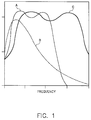
- Figure 1 is a graph illustrating the effect of demagnification on the frequency content of a halftone image.
- Figure 2 illustrates a first implementation of the present invention.
- Figure 3 is a prior art diagram illustrating the functional characteristics of a demagnifying lens.
- Figure 4 illustrates a variable positioning of the demagnifying lens.
- Figure 5 illustrates a means for varying the position of the demagnifying lens.
- Figure 6 is a graph illustrating the effect of image blurring on the frequency content of a halftone image.
- Figure 7 illustrates a second implementation of the present invention.
- Figure 8 illustrates a third implementation of the present invention.
- curve A illustrates the frequency spectrum of a typical halftone image.
- the frequency spectrum will contain contributions from both the image content as well as the halftone patterns used to form the image.
- the halftone patterns will correspond to portions of the frequency spectrum which are higher in frequency than that of the image content. Schematically, this is shown by the two humps in curve A where the left hump is primarily due to the image content, and the right hump is primarily due to the halftone pattern.
- Curve B illustrates the response of the human visual system. It can be seen that both the image content as well as the halftone pattern are within the frequency range at which the observer is sensitive.
- Curve C shows the result of scaling the frequency content of Curve A by a factor of 2.0. It can be seen that the lobe of the curve corresponding to the frequency content of the halftone pattern is now in a frequency range where the human visual system is much less sensitive. As a result, the visibility of the halftone patterns will be substantially reduced.
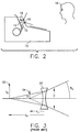
- Figure 2 illustrates an embodiment of the present invention which utilizes a lens with a negative focal length to demagnify the halftone image.
- a point-of-sale terminal l0 contains a dot matrix printer apparatus 12.
- a demagnifying lens 16 forms a virtual image of the receipt image.
- the virtual image will be demagnified relative to the receipt image.
- the observer l8 will view the virtual image which will have reduced visibility of the halftone patterns making up the receipt image. It may be desirable to provide a light source l9 to give uniform and bright illumination to the receipt image.
- the demagnification factor associated with a negative focal length lens can be computed using standard first-order optical equations.
- a lens 20 with focal length f is used to image an object 22 of size y o a distance d o from the lens.
- a virtual image 24 is formed a distance d i from the lens with a size y i .
- the distances d o and d i are measured relative to the lens position, with the sign convention that distances to the right are positive, and distances to the left are negative, so that in this case both distances are negative.
- the image distance d i can be determined from the lens equation:
- the lens 20 has a diameter D
- the angular field-of-view for the system will be: Having a narrow field-of-view may sometimes be a desirable feature for this type of system because in certain cases it may be advantageous to permit the image to be viewable only by the operator of the point-of-sale terminal. However, it would be inconvenient if it were only comfortable for an operator of average height to view the image. For this reason, it is desirable to permit adjustment of the nominal viewing angle. This is accomplished by permitting adjustment of the lens and/or receipt paper positions.
- Figure 4 illustrates an embodiment of the present invention where the lens position is varied to adjust the viewing angle.
- the receipt image 30 is viewed through a demagnifying lens 32.
- the nominal lens position provides the correct viewing angle for an operator of average height 34. If a shorter operator 36 were to use the point-of-sale terminal, the lens position is adjusted to a new location 38 to provide a new nominal viewing angle.
- Many methods could be used to provide the adjustment of the lens and/or receipt paper to permit the adjustment of the nominal viewing angle.
- One such method is shown in Figure 5.
- the receipt paper 40 remains in a fixed position while the lens 42 is moved to provide the adjustment to the viewing angle.
- the lens is positioned in an adjustment slot 44 using a lens mount 46.
- the lens mount is designed so that it can slide back and forth within the adjustment slot.
- a handle can be attached to the lens mount to permit easy adjustment.
- the handle could additionally be designed to function as a locking mechanism.
- the handle could be threaded so that turning the handle would tighten a clamping mechanism.
- Other embodiments of this invention would include adjusting the position of the receipt image, or mounting the receipt lens assembly on a swivel mount to provide the viewing angle alteration.
- FIG. 7 shows a configuration of the present invention which uses a diffuser to provide the image blur.
- a point-of-sale terminal 50 contains a receipt printer 52 which forms an image on the receipt 54.
- a diffuser 56 is used to blur the image so that the visibility of the halftone pattern is reduced for the observer 58.
- the scattering properties of the diffuser, as well as the width of the gap between the receipt and the diffuser will determine the width of the blur function (point spread function).
- the viewing region can be adjusted for this case by recessing the image within the case of the point-of-sale terminal. This would effectively limit the viewing angle in which the observer could view the image.
- the nominal viewing angle could be adjusted by changing the position of the opening of the recess and/or the receipt paper.
- a diffuser could be used to blur the halftone pattern, and a demagnifier could be used to scale the frequency content of the image.
- Figure 8 shows a configuration of the present invention which uses both a demagnifying lens and a diffuser to reduce the visibility of the halftone pattern.
- a point-of-sale terminal 80 contains a receipt printer 82 which forms an image on the receipt 84.
- a diffuser 86 is used to blur the image and a lens 88 is used to demagnify the image so that the visibility of the halftone pattern is reduced for the observer 89.
Landscapes
- Physics & Mathematics (AREA)
- General Physics & Mathematics (AREA)
- Engineering & Computer Science (AREA)
- Optics & Photonics (AREA)
- Multimedia (AREA)
- Signal Processing (AREA)
- Human Computer Interaction (AREA)
- Image Processing (AREA)
- Cash Registers Or Receiving Machines (AREA)
Applications Claiming Priority (2)
| Application Number | Priority Date | Filing Date | Title |
|---|---|---|---|
| US28266794A | 1994-07-29 | 1994-07-29 | |
| US282667 | 1994-07-29 |
Publications (2)
| Publication Number | Publication Date |
|---|---|
| EP0696128A2 true EP0696128A2 (de) | 1996-02-07 |
| EP0696128A3 EP0696128A3 (de) | 1996-03-27 |
Family
ID=23082579
Family Applications (1)
| Application Number | Title | Priority Date | Filing Date |
|---|---|---|---|
| EP95201956A Withdrawn EP0696128A3 (de) | 1994-07-29 | 1995-07-15 | Vorrichtung und Verfahren zur Betrachtung eines Halbtonbildes |
Country Status (2)
| Country | Link |
|---|---|
| EP (1) | EP0696128A3 (de) |
| JP (1) | JPH0863669A (de) |
Cited By (1)
| Publication number | Priority date | Publication date | Assignee | Title |
|---|---|---|---|---|
| US10237523B2 (en) | 2013-05-07 | 2019-03-19 | Dolby Laboratories Licensing Corporation | Digital point spread function (DPSF) and dual modulation projection (including lasers) using DPSF |
Families Citing this family (1)
| Publication number | Priority date | Publication date | Assignee | Title |
|---|---|---|---|---|
| CN109493358A (zh) * | 2018-12-14 | 2019-03-19 | 中国船舶重工集团公司第七0七研究所 | 一种基于人眼视觉模型的误差反馈半色调算法 |
Citations (2)
| Publication number | Priority date | Publication date | Assignee | Title |
|---|---|---|---|---|
| US5214517A (en) | 1990-02-07 | 1993-05-25 | Eastman Kodak Company | Digital halftoning with correlated minimum visual modulation patterns |
| US5321751A (en) | 1993-02-18 | 1994-06-14 | Eastman Kodak Company | Method and apparatus for credit card verification |
Family Cites Families (6)
| Publication number | Priority date | Publication date | Assignee | Title |
|---|---|---|---|---|
| JPS6239376Y2 (de) * | 1980-09-16 | 1987-10-07 | ||
| US4469402A (en) * | 1981-06-15 | 1984-09-04 | Mitsubishi Rayon Co., Ltd. | Rear projection screen |
| US4783680A (en) * | 1987-09-30 | 1988-11-08 | Xerox Corporation | Halftone screening system for printer/copier |
| JPH02162064A (ja) * | 1988-12-16 | 1990-06-21 | Tokyo Electric Co Ltd | カラム式光学ヘッド |
| JPH06189181A (ja) * | 1992-12-22 | 1994-07-08 | Canon Inc | 防振装置を有する中間アダプタ |
| EP0661674A1 (de) * | 1993-12-28 | 1995-07-05 | Eastman Kodak Company | Verfahren und Gerät, mittels eines digitalen Halbtonbildes zum Verkaufszeitpunkt eine Bestätigung vorzunehmen |
-
1995
- 1995-07-15 EP EP95201956A patent/EP0696128A3/de not_active Withdrawn
- 1995-07-25 JP JP7189313A patent/JPH0863669A/ja active Pending
Patent Citations (2)
| Publication number | Priority date | Publication date | Assignee | Title |
|---|---|---|---|---|
| US5214517A (en) | 1990-02-07 | 1993-05-25 | Eastman Kodak Company | Digital halftoning with correlated minimum visual modulation patterns |
| US5321751A (en) | 1993-02-18 | 1994-06-14 | Eastman Kodak Company | Method and apparatus for credit card verification |
Non-Patent Citations (1)
| Title |
|---|
| ULICHNEY: "Digital Halftoning", MIT PRESS, CAMBRIDGE, MASS., pages: 77 - 79, 127 |
Cited By (4)
| Publication number | Priority date | Publication date | Assignee | Title |
|---|---|---|---|---|
| US10237523B2 (en) | 2013-05-07 | 2019-03-19 | Dolby Laboratories Licensing Corporation | Digital point spread function (DPSF) and dual modulation projection (including lasers) using DPSF |
| US11109003B2 (en) | 2013-05-07 | 2021-08-31 | Dolby Laboratories Licensing Corporation | Digital point spread function (DPSF) and dual modulation projection (including lasers) using DPSF |
| US11539927B2 (en) | 2013-05-07 | 2022-12-27 | Dolby Laboratories Licensing Corporation | Digital point spread function (DPSF) and dual modulation projection (including lasers) using DPSF |
| US11889236B2 (en) | 2013-05-07 | 2024-01-30 | Dolby Laboratories Licensing Corporation | Digital point spread function (DPSF) and dual modulation projection (including lasers) using DPSF |
Also Published As
| Publication number | Publication date |
|---|---|
| JPH0863669A (ja) | 1996-03-08 |
| EP0696128A3 (de) | 1996-03-27 |
Similar Documents
| Publication | Publication Date | Title |
|---|---|---|
| US7580153B2 (en) | Printed visible fonts with attendant background | |
| US7324241B2 (en) | Variable data differential gloss images | |
| US7589865B2 (en) | Variable differential gloss font image data | |
| US7148999B2 (en) | Variable glossmark | |
| US6373587B1 (en) | Method for printing electronic tickets | |
| US7027660B2 (en) | Images incorporating microstructures | |
| US6104812A (en) | Anti-counterfeiting method and apparatus using digital screening | |
| JP4712054B2 (ja) | 光沢差のある画像をシミュレートする方法およびシステム | |
| US7982917B2 (en) | Document containing scanning survivable security features | |
| EP1297436B1 (de) | Verfahren zum ausgeben elektronischer tickets | |
| JPH06152928A (ja) | 機械検出可能な安全要素を備えた支持体 | |
| EP1073257B1 (de) | Verfahren zur Erzeugung eines Sicherheitsdokuments | |
| US6580490B1 (en) | Method and apparatus for printing images in multiple formats using a spatial light modulator | |
| Roetling et al. | Digital halftoning | |
| EP0696128A2 (de) | Vorrichtung und Verfahren zur Betrachtung eines Halbtonbildes | |
| US8072649B2 (en) | Image displaying medium, method of generating composite image displaying data and image generating system | |
| EP0789325A2 (de) | Verfahren und Gerät zur wirkungsvollen Bildinterpolation | |
| AU7315998A (en) | A method for printing electronically sharpened images | |
| US5611022A (en) | Color imaging | |
| EP0661674A1 (de) | Verfahren und Gerät, mittels eines digitalen Halbtonbildes zum Verkaufszeitpunkt eine Bestätigung vorzunehmen | |
| US6356291B1 (en) | Method and apparatus for providing print quality enhancement | |
| Stucki | Advances in digital image processing for document reproduction | |
| US5940190A (en) | Image improvement after facsimile reception | |
| Hanson et al. | Review of image enhancement techniques for monochrome and color printing |
Legal Events
| Date | Code | Title | Description |
|---|---|---|---|
| PUAI | Public reference made under article 153(3) epc to a published international application that has entered the european phase |
Free format text: ORIGINAL CODE: 0009012 |
|
| AK | Designated contracting states |
Kind code of ref document: A2 Designated state(s): DE FR GB |
|
| PUAL | Search report despatched |
Free format text: ORIGINAL CODE: 0009013 |
|
| AK | Designated contracting states |
Kind code of ref document: A3 Designated state(s): DE FR GB |
|
| 17P | Request for examination filed |
Effective date: 19960924 |
|
| STAA | Information on the status of an ep patent application or granted ep patent |
Free format text: STATUS: THE APPLICATION HAS BEEN WITHDRAWN |
|
| 18W | Application withdrawn |
Withdrawal date: 19970321 |