EP0695090A1 - Palplus-signal decoder with a cyclic write/read memory control - Google Patents
Palplus-signal decoder with a cyclic write/read memory control Download PDFInfo
- Publication number
- EP0695090A1 EP0695090A1 EP95111192A EP95111192A EP0695090A1 EP 0695090 A1 EP0695090 A1 EP 0695090A1 EP 95111192 A EP95111192 A EP 95111192A EP 95111192 A EP95111192 A EP 95111192A EP 0695090 A1 EP0695090 A1 EP 0695090A1
- Authority
- EP
- European Patent Office
- Prior art keywords
- helper
- image
- memory
- palplus
- signal
- Prior art date
- Legal status (The legal status is an assumption and is not a legal conclusion. Google has not performed a legal analysis and makes no representation as to the accuracy of the status listed.)
- Granted
Links
Images


Classifications
-
- H—ELECTRICITY
- H04—ELECTRIC COMMUNICATION TECHNIQUE
- H04N—PICTORIAL COMMUNICATION, e.g. TELEVISION
- H04N7/00—Television systems
- H04N7/01—Conversion of standards, e.g. involving analogue television standards or digital television standards processed at pixel level
- H04N7/0112—Conversion of standards, e.g. involving analogue television standards or digital television standards processed at pixel level one of the standards corresponding to a cinematograph film standard
-
- H—ELECTRICITY
- H04—ELECTRIC COMMUNICATION TECHNIQUE
- H04N—PICTORIAL COMMUNICATION, e.g. TELEVISION
- H04N11/00—Colour television systems
- H04N11/06—Transmission systems characterised by the manner in which the individual colour picture signal components are combined
- H04N11/12—Transmission systems characterised by the manner in which the individual colour picture signal components are combined using simultaneous signals only
- H04N11/14—Transmission systems characterised by the manner in which the individual colour picture signal components are combined using simultaneous signals only in which one signal, modulated in phase and amplitude, conveys colour information and a second signal conveys brightness information, e.g. NTSC-system
- H04N11/16—Transmission systems characterised by the manner in which the individual colour picture signal components are combined using simultaneous signals only in which one signal, modulated in phase and amplitude, conveys colour information and a second signal conveys brightness information, e.g. NTSC-system the chrominance signal alternating in phase, e.g. PAL-system
- H04N11/167—Transmission systems characterised by the manner in which the individual colour picture signal components are combined using simultaneous signals only in which one signal, modulated in phase and amplitude, conveys colour information and a second signal conveys brightness information, e.g. NTSC-system the chrominance signal alternating in phase, e.g. PAL-system a resolution-increasing signal being multiplexed to the PAL-system signal, e.g. PAL-PLUS-system
-
- H—ELECTRICITY
- H04—ELECTRIC COMMUNICATION TECHNIQUE
- H04N—PICTORIAL COMMUNICATION, e.g. TELEVISION
- H04N19/00—Methods or arrangements for coding, decoding, compressing or decompressing digital video signals
- H04N19/42—Methods or arrangements for coding, decoding, compressing or decompressing digital video signals characterised by implementation details or hardware specially adapted for video compression or decompression, e.g. dedicated software implementation
- H04N19/423—Methods or arrangements for coding, decoding, compressing or decompressing digital video signals characterised by implementation details or hardware specially adapted for video compression or decompression, e.g. dedicated software implementation characterised by memory arrangements
- H04N19/426—Methods or arrangements for coding, decoding, compressing or decompressing digital video signals characterised by implementation details or hardware specially adapted for video compression or decompression, e.g. dedicated software implementation characterised by memory arrangements using memory downsizing methods
- H04N19/427—Display on the fly, e.g. simultaneous writing to and reading from decoding memory
-
- H—ELECTRICITY
- H04—ELECTRIC COMMUNICATION TECHNIQUE
- H04N—PICTORIAL COMMUNICATION, e.g. TELEVISION
- H04N7/00—Television systems
- H04N7/007—Systems with supplementary picture signal insertion during a portion of the active part of a television signal, e.g. during top and bottom lines in a HDTV letter-box system
Definitions
- a transmission in letterbox format takes place in accordance with the PALplus system proposal.
- the 576-line input image is processed in such a way that the vertically low-frequency signal components are transmitted within the central 432 lines of the image.
- the vertically high-frequency signal components are now transmitted in the remaining 144 lines of the image and form the focus information of the image.
- This information is the helper.
- the helper has a low amplitude and is stored in the black area of the image information.
- the helper is invisible to the compatible 4: 3 receiver. Only the central (main) area of the picture is visible to him. 72 lines above and below are black for him (letterbox image).
- the PALplus receiver is now able to reconstruct an image based on the main and helper signals that has the full resolution of the original 576-line image. With the help of vertical filters, the high-frequency information of the helper and the low-frequency information of the main image are added. In addition, with appropriate preprocessing of the signals on the transmitter side, the PALplus receiver is able to suppress crosstalk interference from brightness to color (cross color) and vice versa (cross luminance).
- the process of reconstructing the image depends on the source that provides the image. If there is a film, it has only 25 frames per second, so that both fields of the interlaced image originate from the same movement phase. This is used in the so-called film mode.
- the two partial images are put together again to form a full image and the processing takes place in the full image together with the 144 helper lines of the full image. For images that were recorded with an electronic camera, both fields do not originate from the same movement phase.
- the splitting and reconstruction of the image is carried out on the basis of a partial image including the 72 helper lines of the partial image.
- the method of suppressing crosstalk interference depends on the movement in the image.
- the ColourPlus process is always used for film material, which is based on the receiver side on an addition of the chrominance and the high-frequency luminance of the two fields.
- Motion Adaptive Color Plus (MACP) is used for material from an electronic camera. The same procedure as for film material is used in resting areas or in areas with little movement. If there is a lot of movement in the picture, the ColourPlus reduces it to just 25 movement phases, causing annoying jerking in the picture. For this reason, a horizontal frequency multiplex of luminance and chrominance is already carried out on the transmitter side. This must be taken into account when processing on the receiver side. This requires a motion detector that switches between the two modes.
- Image memories are necessary both for the reconstruction of the full vertical resolution and for the motion-dependent reversal of the cross suppression. Since they belong to the expensive components of the PALplus system, optimal use of the memory is appropriate.
- PALplus decoder with reduced memory requirements is presented and the control of the image memories is described.
- This mode is used when the material in question was recorded by a film camera and accordingly has only 25 movement phases per second.
- every second field is omitted in the chrominance and in the high-frequency luminance after the film scanning at 50 Hz in interlaced lines and the remaining field is repeated once.
- the following PAL modulation and demodulation generally leads to crosstalk interference (cross color and cross luminance), which must be excluded on the receiver side.
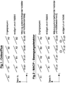
- the processing on the receiver side is shown in Figure 1.
- the incoming sequence (A: first field, B: second field) is delayed by the duration of one field.
- the fields belonging to a frame are now averaged on the basis of the input sequence and the delayed sequence. This averaging is carried out for the chrominance and for the horizontally high-frequency luminance. Due to the properties of the color carrier, this leads to the elimination of the respective crosstalk interference. Subsequent field repetition provides a crosstalk-free sequence with a frame rate of 50 Hz.
- This processing (Color Plus) leads to a transmission of only 25 movement phases for the chrominance and the high-frequency luminance, which is not a limitation with film material.
- the letterbox image is calculated on the transmitter side on a full screen basis.
- the two fields are combined again to form a full picture.
- Subsequent vertical filtering splits the signal into a low-frequency component (16: 9 main image) and a high-frequency component (helper).
- the helper lines are now sorted into the upper and lower letterbox bars.
- In the upper letterbox bars (helper top) of both fields are the helper lines for the upper half of the main image, while those for the lower half of the image can be found in the lower edge lines (helper bottom) of the two fields.
- the ColourPlus process can only be used to a limited extent on sequences that were produced with an electronic camera (50Hz, 2: 1).
- the process-related reduction to 25 movement phases per second in the chrominance and in the horizontally high-frequency Lumianz leads to annoying jerking when moving picture content.
- This procedure can only be carried out when the image content is stationary or moving slowly. In moving image areas, therefore, there is already a horizontal frequency multiplexing of luminance and chrominance on the transmitter side, ie below 3MHz there is only luminance, above only chromiance. This ensures crosstalk-free transmission even for moving image areas.
- a movement-dependent reversal between the two modes must be carried out, which runs synchronously in the transmitter and receiver.
- the motion detection is carried out identically on the basis of the chrominance information in the transmitter and receiver.
- Figure 2 shows the principle. As with the ColorPlus process, two consecutive belongings belonging together are averaged and the result repeated. The resulting picture sequence must now be delayed by the duration of a full picture and the difference between delayed and undelayed picture sequence must be formed. This provides the changeover signal for the method for reducing crosstalk interference. In areas with a large difference there is a lot of movement and horizontal frequency multiplexing of luminance and chrominance has to be carried out. Otherwise ColourPlus can be used.
- helper lines for the upper area of the main image in the first field are in the helper top of the first field, those for the lower half in the helper bottom.
- the helper lines for the second partial image can accordingly be found in the helper areas of the second partial image.
- the helper signal which transmits the vertical height information, must not be visible to the compatible receiver and must still be insensitive to noise. That is why it is subjected to several processing steps.
- the helper signal After the helper signal has been separated from the image signal on the transmitter side, it is subjected to a companding operation which on the one hand limits the amplitude of the helper, and on the other hand amplifies small helper amplitudes more than large ones so that it becomes less sensitive to noise.
- a subsequent horizontal filtering lowers high-frequency helper values slightly and limits the band to around 2.5MHz / -6dB. On the reception side, these steps must be undone.
- a horizontal filter raises high-frequency helper values (inverse spectrum shaping) and a decompanding characteristic compensates for the helper's companding.
- the compander / decompander characteristics of camera and film mode are different, since the helper's amplitudes are usually smaller in film mode than in camera mode, and therefore a lower lowering of the helper makes sense
- helper values in the range of ⁇ 29LSB can occur in the film mode after the decompanding function. These values can be saved with 6 bits.
- the helper values are in the range of ⁇ 87LSB.
- FIG. 4 shows the memory control for the film mode.
- drawing file A1 is composed of the 36 lines of the upper helper (HTA1), the main area (MA1) with 216 lines, and the lower 36 helper lines (HBA1).
- the storage of this data is shown below.
- the first line of HTA1 is stored from block number 2124.
- one line (52us) of the helper occupies 4.5 blocks of the memory.
- Half a block per helper line remains unused. After saving the first helper line, free space is left in the memory for storing the main lines.
- Each main line with 720 samples and 12 bits per sample occupies 18 blocks.
- the areas reserved for this purpose are filled in the memory.
- 5 blocks are left in the memory for the lower helper, which is then sorted.
- the helper lines are now already sorted into the main image in the memory.
- the second field from block number 6372 is now stored in this form.
- the sequential readout of the stored values begins at time t1.
- the main and helper lines of two successive fields (A1 and B1) must be read out simultaneously. This is also possible from a memory module, since they can be read out with 27MHz.
- ColourPlus processing can then be carried out for the main lines and the result made available to the vertical filters for upward conversion.
- the helper lines are fed directly to the vertical filters. Due to the delayed start of reading, the necessary and just received lower helper lines HBB1 are also available to the processing during the second half of the outgoing image.
- both fields are also necessary for the calculation of the second outgoing field (B1 / 16: 9) and must be read out again for this. While reading out these fields, however, the just received field A2 with its helper and main lines must already be saved. A buffer area must be defined so that the still required field A1 is not overwritten. To do this, A1 is saved from block number 0 to number 4247. Write / read conflicts are avoided, because when the last main line from A2 (MA2) is written into blocks 4230 to 4247, the line still required from A1 has just been read out. Field B can always be written to the same memory area since there are no conflicts. To calculate B2 / 16: 9, A2 and B2 can now be read out and calculated. As shown, the space that has just become available is used to save A3. The main area of A3 must be divided into the areas MA3 'and MA3' '.
- Figure 5 shows the memory control for the camera mode including the use of the memory for the motion detector of the Motion Adaptive ColourPlus process.
- the fields A1 and B1 are written in the same way as for the film mode, with the difference that writing begins at block address 3420.
- the range 1296 to 3419 serves as a buffer, as in film mode.
- the motion detector memory is housed in the range 0 to 1295.
- an address offset of 1296 blocks can also be introduced for film mode.
- Reading out begins, as in the film mode at time t1.
- A1 / 16 9 since the splitting was only carried out in the drawing file, only the helper of this drawing file is required.
- the main area of the sub-picture B1 which is now also read out, is necessary for the motion detection and to suppress the crosstalk interference.
- the helper lines from B1 are not yet needed here.
- the memory allocation for the main and helper signals is therefore analogous to that for film mode.
- a memory of 1296 blocks is required for the motion detector.
- MACP 11916 blocks are used for the camera fashion.
- PALplus decoding is possible in both film and camera mode with two memory modules (2.9MBit each).
- the processing modes fully correspond to the PALplus specification Rev. 3.0. This enables a cost-reduced decoder.
- Other circuits for PALplus decoding require four memory modules for the same functions. This not only increases the cost of the memory, it also increases the effort for the PCB and the testing of the module.
Landscapes
- Engineering & Computer Science (AREA)
- Multimedia (AREA)
- Signal Processing (AREA)
- Color Television Image Signal Generators (AREA)
- Color Television Systems (AREA)
Abstract
Description
Zur kompatiblen Übertragung eines Fernsehbildes mit dem Bildseitenverhältnis 16:9 innerhalb eines 4:3-Systems erfolgt entsprechend des PALplus-Systemvorschlags eine Übertragung im Letterboxformat. Dazu wird das 576-zeilige Eingangsbild derart verarbeitet, daß die vertikal niederfrequenten Signalanteile innerhalb der zentralen 432 Zeilen des Bildes übertragen werden. Die vertikal hochfrequenten Signalanteile werden nun in den verbleibenden 144 Zeilen des Bildes übertragen und bilden die Schärfeinformation des Bildes. Diese Information ist der Helper. Der Helper hat eine geringe Amplitude und wird im Schwarzbereich der Bildinformation eingelagert.For the compatible transmission of a television picture with the aspect ratio 16: 9 within a 4: 3 system, a transmission in letterbox format takes place in accordance with the PALplus system proposal. For this purpose, the 576-line input image is processed in such a way that the vertically low-frequency signal components are transmitted within the central 432 lines of the image. The vertically high-frequency signal components are now transmitted in the remaining 144 lines of the image and form the focus information of the image. This information is the helper. The helper has a low amplitude and is stored in the black area of the image information.
Für den kompatiblen 4:3-Empfänger ist der Helper unsichtbar. Für ihn ist nur der zentrale (Main-) bereich des Bildes sichtbar. Jeweils 72 Zeilen oberhalb und unterhalb sind für ihn schwarz (Letterbox-Bild). Der PALplus-Empfänger ist nun in der Lage, auf der Basis der Main- und Helpersignale ein Bild zu rekonstruieren, das die volle Auflösung des ursprünglichen 576-zeiligen Bildes hat. Mit Hilfe von Vertikalfiltern wird dazu die hochfrequente Information des Helpers und die niederfrequente Information des Mainbildes addiert. Außerdem ist der PALplus-Empfänger, bei entsprechender senderseitiger Vorverarbeitung der Signale, in der Lage, Übersprechstörungen von der Helligkeit in die Farbe (Cross Colour) und umgekehrt (Cross Luminanz) zu unterdrücken.The helper is invisible to the compatible 4: 3 receiver. Only the central (main) area of the picture is visible to him. 72 lines above and below are black for him (letterbox image). The PALplus receiver is now able to reconstruct an image based on the main and helper signals that has the full resolution of the original 576-line image. With the help of vertical filters, the high-frequency information of the helper and the low-frequency information of the main image are added. In addition, with appropriate preprocessing of the signals on the transmitter side, the PALplus receiver is able to suppress crosstalk interference from brightness to color (cross color) and vice versa (cross luminance).
Das Verfahren zur Rekonstruktion des Bildes ist abhängig von der Quelle, die das Bild liefert. Liegt ein Film vor, so hat dieser nur 25 Bilder pro Sekunde, so daß beide Teilbilder des Zeilensprungbildes aus der gleichen Bewegungsphase stammen. Dies wird im sogenannten Filmmode ausgenutzt. Die beiden Teilbilder werden wieder zu einem Vollbild zusammengesetzt und die Verarbeitung erfolgt im Vollbild zusammen mit den 144 Helperzeilen des Vollbildes. Für Bildmaterial, das mit einer elektronischen Kamera aufgenommen wurde, stammen beide Halbbilder nicht aus der gleichen Bewegungsphase. Hier erfolgt die Aufspaltung und die Rekonstruktion des Bildes auf der Basis eines Teilbildes incl. der 72 Helperzeilen des Teilbildes.The process of reconstructing the image depends on the source that provides the image. If there is a film, it has only 25 frames per second, so that both fields of the interlaced image originate from the same movement phase. This is used in the so-called film mode. The two partial images are put together again to form a full image and the processing takes place in the full image together with the 144 helper lines of the full image. For images that were recorded with an electronic camera, both fields do not originate from the same movement phase. Here the splitting and reconstruction of the image is carried out on the basis of a partial image including the 72 helper lines of the partial image.
Das Verfahren zur Unterdrückung der Übersprechstörungen hängt ab von der im Bild vorliegenden Bewegung. Für Filmmaterial wird immer das ColourPlus-Verfahren angewendet, das empfängerseitig auf einer Addition der Chrominanz und der hochfrequenten Luminanz der beiden Halbbilder beruht. Für Material einer elektronischen Kamera kommt das Motion Adaptive Colour Plus (MACP) zum Einsatz. In ruhenden Bereichen oder in Bereichen mit wenig Bewegung kommt das gleiche Verfahren wie bei Filmmaterial zum Einsatz. Liegt viel Bewegung im Bild vor, führt die ColourPlus entsprechende Reduktion auf nur 25 Bewegungsphasen zu störendem Rucken im Bild. Deshalb erfolgt für diese Bereiche bereits senderseitig ein horizontaler Frequenzmultiplex von Luminanz und Chrominanz. Dies muß bei der empfängerseitigen Verarbeitung berücksichtigt werden. Dazu ist ein Bewegungsdetektor notwendig, der zwischen beiden Moden umschaltet.The method of suppressing crosstalk interference depends on the movement in the image. The ColourPlus process is always used for film material, which is based on the receiver side on an addition of the chrominance and the high-frequency luminance of the two fields. Motion Adaptive Color Plus (MACP) is used for material from an electronic camera. The same procedure as for film material is used in resting areas or in areas with little movement. If there is a lot of movement in the picture, the ColourPlus reduces it to just 25 movement phases, causing annoying jerking in the picture. For this reason, a horizontal frequency multiplex of luminance and chrominance is already carried out on the transmitter side. This must be taken into account when processing on the receiver side. This requires a motion detector that switches between the two modes.
Sowohl zur Rekonstruktion der vollen Vertikalauflösung, als auch zur bewegungsabhängigen Umsteuerung der Cross-Unterdrückung sind Bildspeicher notwendig. Da sie zu den teuren Komponenten des PALplus-Systems gehören, ist eine optimale Ausnutzung der Speicher angebracht. Hier wird das Konzept eines PALplus-Decoders mit reduziertem Speicheraufwand dargestellt und die Steuerung der Bildspeicher beschrieben.Image memories are necessary both for the reconstruction of the full vertical resolution and for the motion-dependent reversal of the cross suppression. Since they belong to the expensive components of the PALplus system, optimal use of the memory is appropriate. Here the concept of a PALplus decoder with reduced memory requirements is presented and the control of the image memories is described.
Dieser Mode kommt zum Einsatz, wenn das vorliegende Material von einer Filmkamera aufgenommen wurde, und dementsprechend nur 25 Bewegungsphasen pro Sekunde hat. Zur Unterdrückung von Übersprechstörungen wird senderseitig nach der Filmabtastung mit 50Hz im Zeilensprung in der Chrominanz und in der hochfrequenten Luminanz jedes zweite Halbbild weggelassen und das verbleibende je einmal wiederholt. Die nun folgende PAL-Modulation und - Demodulation führt im allgemeinen zu Übersprechstörungen (Cross-Colour und Cross-Luminanz), die empfängerseitig ausgeschlossen werden müssen.This mode is used when the material in question was recorded by a film camera and accordingly has only 25 movement phases per second. In order to suppress crosstalk interference, every second field is omitted in the chrominance and in the high-frequency luminance after the film scanning at 50 Hz in interlaced lines and the remaining field is repeated once. The following PAL modulation and demodulation generally leads to crosstalk interference (cross color and cross luminance), which must be excluded on the receiver side.
Die empfängerseitige Verarbeitung ist in Bild 1 dargestellt. Die eingehende Sequenz (A: erstes Halbbild, B: zweites Halbbild) wird um die Dauer eines Halbbildes verzögert. Auf der Basis der Eingangssequenz und der verzögerten Sequenz erfolgt nun eine Mittelung der zu einem Vollbild gehörigen Halbbilder. Diese Mittelung wird für die Chrominanz und für die horizontal hochfrequente Luminanz ausgeführt. Aufgrund der Eigenschaften des Farbträgers führt dies dazu, daß die jeweiligen Übersprechstörungen elimiert werden. Eine anschließende Halbbildwiederholung liefert eine übersprechfreie Sequenz mit einer Bildfrequenz von 50Hz. Diese Verarbeitung (Colour Plus) führt zu einer Übertragung von nur 25 Bewegungsphasen für die Chrominanz und die hochfrequente Luminanz, was bei Filmmaterial keine Einschränkung darstellt.The processing on the receiver side is shown in Figure 1. The incoming sequence (A: first field, B: second field) is delayed by the duration of one field. The fields belonging to a frame are now averaged on the basis of the input sequence and the delayed sequence. This averaging is carried out for the chrominance and for the horizontally high-frequency luminance. Due to the properties of the color carrier, this leads to the elimination of the respective crosstalk interference. Subsequent field repetition provides a crosstalk-free sequence with a frame rate of 50 Hz. This processing (Color Plus) leads to a transmission of only 25 movement phases for the chrominance and the high-frequency luminance, which is not a limitation with film material.
Die Berechnung des Letterboxbildes erfolgt senderseitig auf Vollbildbasis. Dazu werden die beiden Halbbilder wieder zu einem Vollbild zusammengefaßt. Eine anschließende Vertikalfilterung spaltet das Signal in einen niederfrequenten Anteil (16:9-Mainbild) und einen hochfrequenten Anteil (Helper) auf. Die Helperzeilen werden nun in die oberen und unteren Letterboxbalken einsortiert. In den oberen Letterboxbalken (Helper Top) beider Halbbilder befinden sich die Helperzeilen für die obere Hälfte des Mainbildes, während die für die untere Bildhälfte in den unteren Randzeilen (Helper Bottom) der beiden Halbbilder zu finden sind.The letterbox image is calculated on the transmitter side on a full screen basis. For this purpose, the two fields are combined again to form a full picture. Subsequent vertical filtering splits the signal into a low-frequency component (16: 9 main image) and a high-frequency component (helper). The helper lines are now sorted into the upper and lower letterbox bars. In the upper letterbox bars (helper top) of both fields are the helper lines for the upper half of the main image, while those for the lower half of the image can be found in the lower edge lines (helper bottom) of the two fields.
Im Empfänger müssen zur Rekonstruktion der Auflösung von 576 Zeilen je zwei zusammengehörige Halbbilder wieder zu einem Vollbild zusammengesetzt werden. Mit Hilfe von Vertikalfiltern und der oberen Helperzeilen kann nun die obere Bildhälfte des 16:9- Bildes berechnet werden, während sich die untere Hälfte aus dem unteren Main(Voll-)bild und den unteren Helperzeilen ergibt.To reconstruct the resolution of 576 lines, two fields belonging together must be put together again in the receiver to form a full image. With the help of vertical filters and the upper helper lines, the upper half of the 16: 9 picture can now be calculated, while the lower half results from the lower main (full) picture and the lower helper lines.
Das ColourPlus-Verfahren läßt sich auf Sequenzen, die mit einer elektronischen Kamera (50Hz, 2:1) produziert wurden, nur bedingt anwenden. Die verfahrensbedingte Reduktion auf 25 Bewegungsphasen pro Sekunde in der Chrominanz und in der horizontal hochfrequenten Lumianz führt bei bewegten Bilddinhalten zu störendem Rucken. Dieses Verfahren kann nur bei ruhenden oder langsam bewegten Bildinhalten durchgeführt werden. In bewegten Bildbereichen erfolgt daher bereits senderseitig ein horizontaler Frequenzmultiplex von Luminanz und Chrominanz, d. h. unterhalb von 3MHz befindet sich nur Luminanz, oberhalb nur Chromianz. So ist auch für bewegte Bildbereiche eine übersprechfreie Übertragung sichergestellt. Allerdings muß eine bewegungsabhängige Umsteuerung zwischen beiden Moden durchgeführt werden, die in Sender und Empfänger synchron läuft.The ColourPlus process can only be used to a limited extent on sequences that were produced with an electronic camera (50Hz, 2: 1). The process-related reduction to 25 movement phases per second in the chrominance and in the horizontally high-frequency Lumianz leads to annoying jerking when moving picture content. This procedure can only be carried out when the image content is stationary or moving slowly. In moving image areas, therefore, there is already a horizontal frequency multiplexing of luminance and chrominance on the transmitter side, ie below 3MHz there is only luminance, above only chromiance. This ensures crosstalk-free transmission even for moving image areas. However, a movement-dependent reversal between the two modes must be carried out, which runs synchronously in the transmitter and receiver.
Die Bewegungsdetektion wird auf der Basis der Chrominanzinformation in Sender und Empfänger identisch durchgeführt. Bild 2 zeigt das Prinzip. Wie beim ColorPlus-Verfahren werden je zwei aufeinanderfolgende, zusammengehörige Habbilder gemittelt, und das Ergebnis wiederholt. Die resultierende Bildfolge muß nun um die Dauer eines Vollbildes verzögert werden und die Differenz zwischen verzögerter und unverzögerter Bildfolge gebildet werden. Diese liefert das Umsteuersignal für das Verfahren zur Reduktion der Übersprechstörungen. In Bereichen mit einer großen Differenz liegt viel Bewegung vor und es muß ein horizontaler Frequenzmultiplex von Luminanz und Chrominanz durchgeführt werden. Im anderen Fall kann ColourPlus angewendet werden.The motion detection is carried out identically on the basis of the chrominance information in the transmitter and receiver. Figure 2 shows the principle. As with the ColorPlus process, two consecutive belongings belonging together are averaged and the result repeated. The resulting picture sequence must now be delayed by the duration of a full picture and the difference between delayed and undelayed picture sequence must be formed. This provides the changeover signal for the method for reducing crosstalk interference. In areas with a large difference there is a lot of movement and horizontal frequency multiplexing of luminance and chrominance has to be carried out. Otherwise ColourPlus can be used.
Die Aufspaltung in Main- und Helperbereich erfolgt in diesem Mode auf Teilbildbasis. Die Helperzeilen für den oberen Bereich des Mainbildes des ersten Halbbildes befinden sich im Helper Top des ersten Halbbildes, die für die untere Bildhälfte im Helper Bottom. Die Helperzeilen für das zweite Teilbild sind dementsprechend in den Helperbereichen des zweiten Teilbildes zu finden.In this mode, the division into the main and helper areas takes place on a sub-image basis. The helper lines for the upper area of the main image in the first field are in the helper top of the first field, those for the lower half in the helper bottom. The helper lines for the second partial image can accordingly be found in the helper areas of the second partial image.
Das Helpersignal, welches die vertikalen Höheninformationen überträgt, darf für den kompatiblen Empfänger nicht sichtbar sein und muß totzdem rauschunempfindlich sein. Deshalb wird es mehreren Verarbeitungschritten unterzogen. Nachdem das Helpersignal auf der Senderseite vom Bildsignal abgetrennt worden ist, wird es einer Companding-Operation unterzogen, die zum einen die Amplitude des Helpers begrenzt, und zum anderen kleine Helperamplituden mehr verstärkt als große, so daß es rauschunempfindlicher wird. Eine anschließende Horizontalfilterung senkt hochfrequente Helperwerte leicht ab und führt eine Bandbegrenzung auf etwa 2.5MHz/-6dB durch. Empfangsseitig müssen diese Schritte wieder rückgängig gemacht werden. Ein Horizontalfilter hebt hochfrequente Helperwerte an (Inverse Spectrum Shaping) und eine Decompanding-Kennlinie gleicht die senderseitige Compandierung des Helpers aus. Die Compander/Decompander-Kennlinien von Kamera- und Filmmode sind unterschiedlich, da die Amplituden des Helpers im Filmmode in der Regel kleiner sind, als im Cameramode, und deshalb in diesem Mode eine geringere Absenkung des Helpers sinnvoll ist.The helper signal, which transmits the vertical height information, must not be visible to the compatible receiver and must still be insensitive to noise. That is why it is subjected to several processing steps. After the helper signal has been separated from the image signal on the transmitter side, it is subjected to a companding operation which on the one hand limits the amplitude of the helper, and on the other hand amplifies small helper amplitudes more than large ones so that it becomes less sensitive to noise. A subsequent horizontal filtering lowers high-frequency helper values slightly and limits the band to around 2.5MHz / -6dB. On the reception side, these steps must be undone. A horizontal filter raises high-frequency helper values (inverse spectrum shaping) and a decompanding characteristic compensates for the helper's companding. The compander / decompander characteristics of camera and film mode are different, since the helper's amplitudes are usually smaller in film mode than in camera mode, and therefore a lower lowering of the helper makes sense in this mode.
Bei der vorliegenden Bandbreite des Helpers ist eine Abtastfrequenz von 6.75MHz ausreichend, um ihn im Empfänger ohne Informationsverlust abspeichern zu können. Das Luminanzsignal des Mainbildes mit einer Bandbreite von 5MHz muß allerdings mit 13.5MHz abgetastet und gespeichert werden. Infolge des Compandings und Decompandings des Helpers bei der Übertragung wird der mögliche Wertebereich des Helpers eingeschränkt. Entsprechend der PALplus-Spezifikation können im Filmmode nach der Decompandingfunktion Helperwerte im Bereich von ±29LSB (bezogen auf 8Bit) auftreten. Die Abspeicherung dieser Werte ist mit 6Bit möglich. Im Cameramode liegen die Helperwerte im Bereich ±87LSB. Eine Begrenzung dieses Bereichs auf ±64LSB und Rundung auf gerade Helperwerte führt zu keinen sichtbaren Störungen im Bild. Damit läßt sich auch im Cameramode der Helper mit 6Bit darstellen und abspeichern. Für beide Mode ist damit eine optimierte Abspeicherung des Helpers mit einer Abtastfrequenz von 6.75MHz und einer Amplitudenquantisierung mit 6Bit möglich.Given the bandwidth of the helper, a sampling frequency of 6.75 MHz is sufficient to be able to save it in the receiver without loss of information. The luminance signal of the main image with a bandwidth of 5MHz must be sampled and stored at 13.5MHz. As a result of the helper's companding and decompanding during transmission, the helper's possible range of values is restricted. According to the PALplus specification, helper values in the range of ± 29LSB (based on 8Bit) can occur in the film mode after the decompanding function. These values can be saved with 6 bits. In camera mode, the helper values are in the range of ± 87LSB. Limiting this range to ± 64LSB and rounding to straight helper values does not lead to any visible disturbances in the image. This allows the helper to be displayed and saved in 6-bit mode. For both modes, an optimized storage of the helper with a sampling frequency of 6.75 MHz and an amplitude quantization with 6 bits is possible.
Bild 3 zeigt das Gesamtsystem zur PALplus-Decodierung. Das eingehende Bild soll als bereits digitalisiert angenommen werden (Quantisiert mit 8Bit). Das Luminanzsignal ist mit 13.5MHz abgetastet worden, das Helpersignal mit 6.75MHz. Alternativ kann auch das Helpersignal mit 13.5MHz abgetastet und anschließend einer Anwärtskonversion im Verhältnis 2:1 unterzogen werden. Die Chrominanz sei bereits demoduliert und mit 3.375MHz abgetastet (4:1:1-System) worden. Das Helpersignal wird nun der Horizontalfilterung zur Spektrenformung unterzogen und anschließend der Look-up-Tabelle zwecks Decompanding zugeführt. Nun kann die Amplitudenauflösung für das Helpersignal auf 6Bit reduziert und das Signal gespeichert werden. Das Mainsignal wird an diesen Operationen vorbeigeführt und ebenfalls gespeichert. Das PALplus-Processing führt nun folgende Operationen aus:
- im Filmmode:
- ColourPlus zur Reduktion der Übersprechstörungen
vertikale Formatkonversion im Vollbild unter Nutzung des Helpersignals (nach Aufwärtskonversion auf 13.5MHz) - im Cameramode:
- Motion Adaptive ColourPlus zur Reduktion der Übersprechstörungen
vertikale Formatkonversion im Teilbild unter Nutzung des Helpersignals (nach Aufwärtskonversion auf 13.5MHz)
- in film mode:
- ColourPlus to reduce crosstalk interference
vertical format conversion in full screen using the helper signal (after upconversion to 13.5MHz) - in camera fashion:
- Motion Adaptive ColourPlus to reduce crosstalk interference
vertical format conversion in the partial image using the helper signal (after upward conversion to 13.5MHz)
Für das PALplus-Processing stehen zwei Speicher zur Verfügung. In Speicher 2 kann nur das eingehende Bildsignal geschrieben werden, während in Speicher 1 auch bereits verarbeitete Werte geschrieben werden können. Die Speichersteuerung wird hier beispielhaft für Speicherbausteine mit der Organisation 6144Blocks*40Worte*12Bit beschrieben (TMS4C2971 von Texas Instruments). Jeder Block ist einzeln adressierbar und der Speicher hat einen Schreib- und einen Leseport (Dual Port Memory). Die Blocknummern 1-6144 seien Memory 1 zugeordnet, während sich die Blöcke 6145- 12288 im Memory 2 befinden. Bei den Beschreibungen der Speichersteuerungen sollen folgende Abkürzungen gelten:
- A:
- erstes Halbbild
- B:
- zweites Halbbild
- HT:
- oberer Helper (Helper Top)
- HB:
- unterer Helper (Helper Bottom)
- M:
- zentraler Bildbereich (Main)
- A' (A''):
- erster (zweiter) Teil des ersten Teilbildes
- ______
- Speicher schreiben
- ...........
- Speicher lesen
- A:
- first field
- B:
- second field
- HT:
- upper helper (helper top)
- HB:
- Bottom helper (Helper Bottom)
- M:
- central image area (Main)
- A '(A''):
- first (second) part of the first field
- ______
- Write memory
- ...........
- Read memory
Bild 4 zeigt die Speichersteuerung für den Filmmode. Oben ist das eingehende Bild dargestellt. Dementsprechend setzt sich das Teilbild A1 aus den 36 Zeilen des oberen Helpers (HTA1), dem Mainbereich (MA1) mit 216 Zeilen, sowie den unteren 36 Helperzeilen (HBA1) zusammen. Unten ist die Abspeicherung dieser Daten dargestellt. Die erste Zeile von HTA1 wird ab Blocknummer 2124 abgelegt. Infolge der Quantisierung mit nur 6Bit pro Abtastwert und der Abtastung mit 6.75MHz belegt eine Zeile (52us) des Helpers 4.5 Blöcke des Speichers. Ein halber Block pro Helperzeile bleibt ungenutzt. Nach Abspeicherung der ersten Helperzeile wird im Speicher freier Platz zur Abspeicherung der Mainzeilen gelassen. Jede Mainzeile mit 720 Abtastwerten und 12Bit pro Abtastwert (wegen des 4:1:1-Systems) belegt 18 Blöcke. Auf jede Helperzeile kommen drei Mainzeile, so daß die nächste Helperzeile ab Blocknummer 2183 abgelegt wird. Mit Beginn des Mainbereichs MA1 werden die hierfür freigehaltenen Bereiche im Speicher aufgefüllt. Während der zweiten Hälfte des Mainbildes werden im Speicher jeweils 5 Blöcke für den unteren Helper freigelassen, der abschließend einsortiert wird. Im Speicher sind nun die Helperzeilen bereits in das Mainbild einsortiert. In dieser Form wird nun das zweite Halbbild ab Blocknummer 6372 abgelegt.Figure 4 shows the memory control for the film mode. The incoming picture is shown above. Correspondingly, drawing file A1 is composed of the 36 lines of the upper helper (HTA1), the main area (MA1) with 216 lines, and the lower 36 helper lines (HBA1). The storage of this data is shown below. The first line of HTA1 is stored from block number 2124. As a result of the quantization with only 6 bits per sample and the sampling with 6.75 MHz, one line (52us) of the helper occupies 4.5 blocks of the memory. Half a block per helper line remains unused. After saving the first helper line, free space is left in the memory for storing the main lines. Each main line with 720 samples and 12 bits per sample (because of the 4: 1: 1 system) occupies 18 blocks. There are three main lines on each helper line, so that the next helper line is stored starting with block number 2183. At the beginning of the main area MA1, the areas reserved for this purpose are filled in the memory. During the second half of the main picture, 5 blocks are left in the memory for the lower helper, which is then sorted. The helper lines are now already sorted into the main image in the memory. The second field from block number 6372 is now stored in this form.
Zum Zeitpunkt t1 beginnt das sequentielle Auslesen der gespeicherten Werte. Für die Filmodeverarbeitung müssen die Main- und Helperzeilen von zwei aufeinanderfolgenden Halbbildern (A1 und B1) gleichzeitig ausgelesen werden. Dies ist auch aus einem Speicherbaustein möglich, da sie mit 27MHz ausgelesen werden können. Für die Mainzeilen kann dann die ColourPlus-Verarbeitung durchgeführt und das Result den Vertikalfiltern zur Aufwärtskonversion zur Verfügung gestellt werden. Die Helperzeilen werden den Vertikalfiltern direkt zugeführt. Durch den verzögerten Auslesebeginn stehen der Verarbeitung während der zweiten Hälfte des ausgehenden Bildes auch die notwendigen, und gerade eingegangenen, unteren Helperzeilen HBB1 zur Verfügung.The sequential readout of the stored values begins at time t1. For film code processing, the main and helper lines of two successive fields (A1 and B1) must be read out simultaneously. This is also possible from a memory module, since they can be read out with 27MHz. ColourPlus processing can then be carried out for the main lines and the result made available to the vertical filters for upward conversion. The helper lines are fed directly to the vertical filters. Due to the delayed start of reading, the necessary and just received lower helper lines HBB1 are also available to the processing during the second half of the outgoing image.
Wegen der Vollbildverarbeitung im Filmmode sind auch für die Berechnung des zweiten ausgehenden Halbbildes (B1/16:9) beide Halbbilder (A1 und B1) notwendig und müssen hierfür noch einmal ausgelesen werden. Während des Auslesens dieser Halbbilder muß aber bereits das soeben eingehende Halbbild A2 mit seinen Helper- und Mainzeilen abgespeichert werden. Damit nun nicht das noch benötigte Halbbild A1 überschrieben wird, muß ein Bufferbereich definiert werden. Dazu wird A1 ab der Blocknummer 0 bis zur Nummer 4247 gespeichert. Schreib/Lesekonflikte werden vermieden, denn, wenn die letzte Mainzeile von A2 (MA2) in die Blöcke 4230 bis 4247 geschrieben wird, ist die noch benötigte Zeile von A1 gerade ausgelesen worden. Halbbild B kann immer in den gleichen Speicherbereich geschrieben werden, da keine Konflikte auftreten. Zur Berechnung von B2/16:9 können nun A2 und B2 ausgelesen und verrechnet werden. Zur Abspeicherung von A3 wird, wie dargestellt, der gerade freigewordene Speicherplatz genutzt. Der Mainbereich von A3 muß dazu in die Bereiche MA3' und MA3'' geteilt werden.Because of the full-screen processing in film mode, both fields (A1 and B1) are also necessary for the calculation of the second outgoing field (B1 / 16: 9) and must be read out again for this. While reading out these fields, however, the just received field A2 with its helper and main lines must already be saved. A buffer area must be defined so that the still required field A1 is not overwritten. To do this, A1 is saved from block number 0 to
Es ergibt sich somit eine zyklische Schreib/Lesesteuerung über 6 Halbbilder. Durch die optimierte Abspeicherung des Helpersignals und die Steuerung der Speicher reicht für diesen Mode ein Speicherplatz von 10620 Blöcken (von 12288 verfügbaren) aus.This results in a cyclic write / read control over 6 fields. Due to the optimized storage of the helper signal and the control of the memory, a memory space of 10620 blocks (of 12288 available) is sufficient for this mode.
Bild 5 zeigt die Speichersteuerung für den Cameramode incl. der Nutzung der Speicher für den Bewegungsdetektor des Motion Adaptive ColourPlus-Verfahrens. Das Einschreiben der Halbbilder A1 und B1 erfolgt analog zum Filmmode, mit dem Unterschied, daß ab Blockadresse 3420 eingeschrieben wird. Der Bereich 1296 bis 3419 dient, wie im Filmmode als Buffer. Im Bereich 0 bis 1295 wird der Bewegungsdetektorspeicher untergebracht. Um die Speichersteuerung für Camera- und Filmmode weitgehend identisch auslegen zu können, kann auch für den Filmmode ein Adressoffset von 1296 Blöcken eingeführt werden.Figure 5 shows the memory control for the camera mode including the use of the memory for the motion detector of the Motion Adaptive ColourPlus process. The fields A1 and B1 are written in the same way as for the film mode, with the difference that writing begins at block address 3420. The range 1296 to 3419 serves as a buffer, as in film mode. The motion detector memory is housed in the range 0 to 1295. In order to be able to design the memory control for camera and film mode largely identically, an address offset of 1296 blocks can also be introduced for film mode.
Das Auslesen beginnt, wie im Filmmode zum Zeitpunkt t1. Für das Teilbild A1/16:9 wird, da die Aufspaltung nur im Teilbild ausgeführt wurde, auch nur der Helper dieses Teilbildes benötigt. Allerdings ist für die Bewegungsdetektion und zur Unterdrückung der Übersprechstörungen der Mainbereich des Teilbildes B1 notwendig, der nun ebenfalls ausgelesen wird. Die Helperzeilen von B1 werden hier noch nicht benötigt.Reading out begins, as in the film mode at time t1. For the drawing file A1 / 16: 9, since the splitting was only carried out in the drawing file, only the helper of this drawing file is required. However, the main area of the sub-picture B1, which is now also read out, is necessary for the motion detection and to suppress the crosstalk interference. The helper lines from B1 are not yet needed here.
Im Speicherbereich 0 bis 1295 befindet sich jeweils die gemittelte Chroma des Mainbereichs von zwei zusammengehörigen Halbbildern (![]()
![]()
Die Speicherbelegung für die Main- und Helpersignale erfolgt also analog zu der beim Filmmode. Zusätzlich ist noch ein Speicher von 1296 Blöcken für den Bewegungsdetektor notwendig. Insgesamt werden damit für den Cameramode mit MACP 11916 Blöcke belegt.The memory allocation for the main and helper signals is therefore analogous to that for film mode. In addition, a memory of 1296 blocks is required for the motion detector. Overall, MACP 11916 blocks are used for the camera fashion.
Durch eine optimierte Abspeicherung des Helpersignals und die dargestellte Speichersteuerung ist die PALplus-Decodierung sowohl im Film- als auch im Kameramode mit zwei Speicherbausteinen (je 2.9MBit) möglich. Die Verarbeitungsmoden entsprechen voll der PALplus-Spezifikation Rev. 3.0. Damit ist ein kostenreduzierter Decoder möglich. Andere Schaltungen zur PALplus-Decodierung benötigen für die gleichen Funktionen vier Speicherbausteine. Dadurch sind nicht nur die Kosten für den Speicher höher, sonderen es erhöht sich auch der Aufwand für das PCB und den Test des Moduls.Thanks to an optimized storage of the helper signal and the memory control shown, PALplus decoding is possible in both film and camera mode with two memory modules (2.9MBit each). The processing modes fully correspond to the PALplus specification Rev. 3.0. This enables a cost-reduced decoder. Other circuits for PALplus decoding require four memory modules for the same functions. This not only increases the cost of the memory, it also increases the effort for the PCB and the testing of the module.
Claims (5)
Applications Claiming Priority (2)
| Application Number | Priority Date | Filing Date | Title |
|---|---|---|---|
| DE4426382A DE4426382A1 (en) | 1994-07-26 | 1994-07-26 | Decoder for PALplus signals with a cyclic read / write memory control |
| DE4426382 | 1994-07-26 |
Publications (2)
| Publication Number | Publication Date |
|---|---|
| EP0695090A1 true EP0695090A1 (en) | 1996-01-31 |
| EP0695090B1 EP0695090B1 (en) | 1999-08-25 |
Family
ID=6524133
Family Applications (1)
| Application Number | Title | Priority Date | Filing Date |
|---|---|---|---|
| EP95111192A Expired - Lifetime EP0695090B1 (en) | 1994-07-26 | 1995-07-15 | PALplus-signal decoder with a cyclic write/read memory control |
Country Status (3)
| Country | Link |
|---|---|
| EP (1) | EP0695090B1 (en) |
| DE (2) | DE4426382A1 (en) |
| FI (1) | FI953554A (en) |
Cited By (5)
| Publication number | Priority date | Publication date | Assignee | Title |
|---|---|---|---|---|
| EP0762748A2 (en) * | 1995-08-30 | 1997-03-12 | Sony Corporation | Low-memory line interpolation for a PAL-plus television receiver |
| EP0804041A2 (en) * | 1996-04-26 | 1997-10-29 | Sony Corporation | Video signal processing apparatus for an improved definition television receiver |
| EP0804029A2 (en) * | 1996-04-26 | 1997-10-29 | Sony Corporation | Video signal processing apparatus |
| EP0806877A2 (en) * | 1996-05-08 | 1997-11-12 | Deutsche Thomson-Brandt Gmbh | Method and device for the processing of a composite colour video signal with an optimized memory capacity |
| EP0833510A2 (en) * | 1996-09-27 | 1998-04-01 | SONY DEUTSCHLAND GmbH | Method and device for decoding a television signal in a wide-screen reproduction mode |
Citations (1)
| Publication number | Priority date | Publication date | Assignee | Title |
|---|---|---|---|---|
| DE4243804A1 (en) * | 1992-12-23 | 1994-07-07 | Grundig Emv | Receiver for processing letterbox television signals |
Family Cites Families (1)
| Publication number | Priority date | Publication date | Assignee | Title |
|---|---|---|---|---|
| NL194023C (en) * | 1983-05-06 | 2001-04-03 | Philips Electronics Nv | Color television transmission or information storage system with time-division multiplex encoding and suitable information transmitter and receiver. |
-
1994
- 1994-07-26 DE DE4426382A patent/DE4426382A1/en not_active Withdrawn
-
1995
- 1995-07-15 DE DE59506677T patent/DE59506677D1/en not_active Expired - Fee Related
- 1995-07-15 EP EP95111192A patent/EP0695090B1/en not_active Expired - Lifetime
- 1995-07-25 FI FI953554A patent/FI953554A/en unknown
Patent Citations (1)
| Publication number | Priority date | Publication date | Assignee | Title |
|---|---|---|---|---|
| DE4243804A1 (en) * | 1992-12-23 | 1994-07-07 | Grundig Emv | Receiver for processing letterbox television signals |
Cited By (11)
| Publication number | Priority date | Publication date | Assignee | Title |
|---|---|---|---|---|
| EP0762748A2 (en) * | 1995-08-30 | 1997-03-12 | Sony Corporation | Low-memory line interpolation for a PAL-plus television receiver |
| EP0762748A3 (en) * | 1995-08-30 | 1999-02-03 | Sony Corporation | Low-memory line interpolation for a PAL-plus television receiver |
| EP0804041A2 (en) * | 1996-04-26 | 1997-10-29 | Sony Corporation | Video signal processing apparatus for an improved definition television receiver |
| EP0804029A2 (en) * | 1996-04-26 | 1997-10-29 | Sony Corporation | Video signal processing apparatus |
| EP0804029A3 (en) * | 1996-04-26 | 1999-07-21 | Sony Corporation | Video signal processing apparatus |
| EP0804041A3 (en) * | 1996-04-26 | 1999-07-28 | Sony Corporation | Video signal processing apparatus for an improved definition television receiver |
| EP0806877A2 (en) * | 1996-05-08 | 1997-11-12 | Deutsche Thomson-Brandt Gmbh | Method and device for the processing of a composite colour video signal with an optimized memory capacity |
| EP0806877A3 (en) * | 1996-05-08 | 1997-11-19 | Deutsche Thomson-Brandt Gmbh | Method and device for the processing of a composite colour video signal with an optimized memory capacity |
| US6118487A (en) * | 1996-05-08 | 2000-09-12 | Deutsch Thompson-Brandt Gmbh | Method and circuit arrangement for the memory-optimized processing of a composite video baseband signal CVBS signal |
| EP0833510A2 (en) * | 1996-09-27 | 1998-04-01 | SONY DEUTSCHLAND GmbH | Method and device for decoding a television signal in a wide-screen reproduction mode |
| EP0833510A3 (en) * | 1996-09-27 | 1998-04-29 | SONY DEUTSCHLAND GmbH | Method and device for decoding a television signal in a wide-screen reproduction mode |
Also Published As
| Publication number | Publication date |
|---|---|
| DE59506677D1 (en) | 1999-09-30 |
| FI953554A0 (en) | 1995-07-25 |
| DE4426382A1 (en) | 1996-02-01 |
| FI953554A (en) | 1996-01-27 |
| EP0695090B1 (en) | 1999-08-25 |
Similar Documents
| Publication | Publication Date | Title |
|---|---|---|
| DE3650353T2 (en) | COMPATIBILITY OF TELEVISION BROADCASTING WITH ENLARGED AND NORMAL PICTURE FORMAT. | |
| AT391967B (en) | COLOR TELEVISION PLAYER | |
| DE69220391T2 (en) | Dual-range progressive scan converter with noise reduction | |
| DE69221744T2 (en) | Video noise reduction system using multiple frequency bands | |
| EP0175860B1 (en) | Method to compatibly increase the definition of a colour television transmission system with cross-talk interference reduction by means of picture processing | |
| DD292801A5 (en) | COMPATIBLE TELEVISION TRANSMISSION SYSTEM AND COMPATIBLE RECEIVER AND TRANSMITTER FOR A TV SERIAL SIGNAL | |
| EP0176674B1 (en) | Method to increase the definition of a compatible television system | |
| DE69830471T2 (en) | Interpolator with a weighted median filter | |
| AT395667B (en) | COLOR TELEVISION PLAYER | |
| DD292797A5 (en) | ARRANGEMENT FOR PROCESSING A WIDE PHOTOGRAPHIC SIGNAL WITH AN INTERPOLATOR FOR REDUCING PICTORIAL FACTORS | |
| DE3341393C2 (en) | Method for transmitting a television signal of higher resolution | |
| DE69902962T2 (en) | Method and apparatus for converting interlaced scan video signal to continuous scan video signal | |
| DE3841173C1 (en) | Compatible television transmission system | |
| DE19757748B4 (en) | Automatic picture format converter device for television receivers | |
| DE3344524A1 (en) | METHOD FOR COMPATIBLE RESOLUTION ENHANCEMENT FOR COLOR TELEVISION TRANSMISSION SYSTEMS | |
| DE2319820C3 (en) | Line sequential encoder and decoder for a color television recording system | |
| DE4423226C1 (en) | Digital decoding composite video, blanking and synchronisation signals | |
| EP0806877B1 (en) | Method and device for the processing of a composite colour video signal with an optimized memory capacity | |
| EP0695090B1 (en) | PALplus-signal decoder with a cyclic write/read memory control | |
| DE3782814T2 (en) | TELEVISION IMPROVEMENTS. | |
| DE3686505T2 (en) | METHOD AND SYSTEM FOR DEGREASING NTSC COLOR VIDEO SIGNALS. | |
| EP0432529B1 (en) | Method for transmitting widescreen videosignals to be displayed on television receivers with conventional or wider aspect ratio | |
| DE68922741T2 (en) | TRANSMISSION SYSTEM OF B-MAC TELEVISION SIGNALS WITH HIGH RESOLUTION. | |
| DE69024012T2 (en) | Device for processing a video signal. | |
| DE69015676T2 (en) | Device for converting the frame rate for an HDTV television receiver and method for motion detection in an encoded television picture. |
Legal Events
| Date | Code | Title | Description |
|---|---|---|---|
| PUAI | Public reference made under article 153(3) epc to a published international application that has entered the european phase |
Free format text: ORIGINAL CODE: 0009012 |
|
| AK | Designated contracting states |
Kind code of ref document: A1 Designated state(s): DE DK ES FR GB IT SE |
|
| 17P | Request for examination filed |
Effective date: 19960626 |
|
| 17Q | First examination report despatched |
Effective date: 19980420 |
|
| GRAG | Despatch of communication of intention to grant |
Free format text: ORIGINAL CODE: EPIDOS AGRA |
|
| GRAG | Despatch of communication of intention to grant |
Free format text: ORIGINAL CODE: EPIDOS AGRA |
|
| GRAH | Despatch of communication of intention to grant a patent |
Free format text: ORIGINAL CODE: EPIDOS IGRA |
|
| GRAH | Despatch of communication of intention to grant a patent |
Free format text: ORIGINAL CODE: EPIDOS IGRA |
|
| GRAA | (expected) grant |
Free format text: ORIGINAL CODE: 0009210 |
|
| AK | Designated contracting states |
Kind code of ref document: B1 Designated state(s): DE DK ES FR GB IT SE |
|
| PG25 | Lapsed in a contracting state [announced via postgrant information from national office to epo] |
Ref country code: SE Free format text: THE PATENT HAS BEEN ANNULLED BY A DECISION OF A NATIONAL AUTHORITY Effective date: 19990825 Ref country code: IT Free format text: LAPSE BECAUSE OF FAILURE TO SUBMIT A TRANSLATION OF THE DESCRIPTION OR TO PAY THE FEE WITHIN THE PRESCRIBED TIME-LIMIT;WARNING: LAPSES OF ITALIAN PATENTS WITH EFFECTIVE DATE BEFORE 2007 MAY HAVE OCCURRED AT ANY TIME BEFORE 2007. THE CORRECT EFFECTIVE DATE MAY BE DIFFERENT FROM THE ONE RECORDED. Effective date: 19990825 Ref country code: GB Free format text: LAPSE BECAUSE OF FAILURE TO SUBMIT A TRANSLATION OF THE DESCRIPTION OR TO PAY THE FEE WITHIN THE PRESCRIBED TIME-LIMIT Effective date: 19990825 Ref country code: FR Free format text: LAPSE BECAUSE OF FAILURE TO SUBMIT A TRANSLATION OF THE DESCRIPTION OR TO PAY THE FEE WITHIN THE PRESCRIBED TIME-LIMIT Effective date: 19990825 Ref country code: ES Free format text: THE PATENT HAS BEEN ANNULLED BY A DECISION OF A NATIONAL AUTHORITY Effective date: 19990825 |
|
| REF | Corresponds to: |
Ref document number: 59506677 Country of ref document: DE Date of ref document: 19990930 |
|
| PG25 | Lapsed in a contracting state [announced via postgrant information from national office to epo] |
Ref country code: DK Free format text: LAPSE BECAUSE OF FAILURE TO SUBMIT A TRANSLATION OF THE DESCRIPTION OR TO PAY THE FEE WITHIN THE PRESCRIBED TIME-LIMIT Effective date: 19991125 |
|
| EN | Fr: translation not filed | ||
| GBV | Gb: ep patent (uk) treated as always having been void in accordance with gb section 77(7)/1977 [no translation filed] |
Effective date: 19990825 |
|
| PLBE | No opposition filed within time limit |
Free format text: ORIGINAL CODE: 0009261 |
|
| STAA | Information on the status of an ep patent application or granted ep patent |
Free format text: STATUS: NO OPPOSITION FILED WITHIN TIME LIMIT |
|
| 26N | No opposition filed | ||
| PGFP | Annual fee paid to national office [announced via postgrant information from national office to epo] |
Ref country code: DE Payment date: 20070720 Year of fee payment: 13 |
|
| PG25 | Lapsed in a contracting state [announced via postgrant information from national office to epo] |
Ref country code: DE Free format text: LAPSE BECAUSE OF NON-PAYMENT OF DUE FEES Effective date: 20090203 |