EP0694847A2 - Datenströmung in einem Rechnersystem - Google Patents
Datenströmung in einem Rechnersystem Download PDFInfo
- Publication number
- EP0694847A2 EP0694847A2 EP95305073A EP95305073A EP0694847A2 EP 0694847 A2 EP0694847 A2 EP 0694847A2 EP 95305073 A EP95305073 A EP 95305073A EP 95305073 A EP95305073 A EP 95305073A EP 0694847 A2 EP0694847 A2 EP 0694847A2
- Authority
- EP
- European Patent Office
- Prior art keywords
- data
- control unit
- devices
- data stream
- control units
- Prior art date
- Legal status (The legal status is an assumption and is not a legal conclusion. Google has not performed a legal analysis and makes no representation as to the accuracy of the status listed.)
- Withdrawn
Links
- 239000000872 buffer Substances 0.000 claims abstract description 285
- 238000012545 processing Methods 0.000 claims abstract description 68
- 230000006870 function Effects 0.000 claims abstract description 55
- 238000004891 communication Methods 0.000 claims abstract description 49
- 230000000977 initiatory effect Effects 0.000 claims abstract description 21
- 238000002360 preparation method Methods 0.000 claims abstract description 13
- 230000011664 signaling Effects 0.000 claims abstract description 10
- 238000000034 method Methods 0.000 claims description 80
- 230000008569 process Effects 0.000 claims description 79
- 230000009471 action Effects 0.000 claims description 46
- 230000002093 peripheral effect Effects 0.000 claims description 22
- 238000012546 transfer Methods 0.000 claims description 9
- 230000004044 response Effects 0.000 claims description 3
- 230000001143 conditioned effect Effects 0.000 claims description 2
- 238000013501 data transformation Methods 0.000 claims 1
- 230000033001 locomotion Effects 0.000 abstract description 10
- 230000001360 synchronised effect Effects 0.000 abstract description 3
- 238000010586 diagram Methods 0.000 description 11
- 238000011144 upstream manufacturing Methods 0.000 description 7
- 230000001934 delay Effects 0.000 description 4
- 238000007726 management method Methods 0.000 description 4
- 230000009466 transformation Effects 0.000 description 4
- 230000001419 dependent effect Effects 0.000 description 3
- 230000007246 mechanism Effects 0.000 description 3
- 230000008520 organization Effects 0.000 description 3
- 230000001186 cumulative effect Effects 0.000 description 2
- 230000000694 effects Effects 0.000 description 2
- 230000006978 adaptation Effects 0.000 description 1
- 230000002411 adverse Effects 0.000 description 1
- 230000008901 benefit Effects 0.000 description 1
- 230000008859 change Effects 0.000 description 1
- 230000005465 channeling Effects 0.000 description 1
- 238000006243 chemical reaction Methods 0.000 description 1
- 230000003750 conditioning effect Effects 0.000 description 1
- 238000010276 construction Methods 0.000 description 1
- 230000006837 decompression Effects 0.000 description 1
- 238000005516 engineering process Methods 0.000 description 1
- 230000006872 improvement Effects 0.000 description 1
- 238000002789 length control Methods 0.000 description 1
- 238000012544 monitoring process Methods 0.000 description 1
- 238000005192 partition Methods 0.000 description 1
- 238000011084 recovery Methods 0.000 description 1
- 239000013589 supplement Substances 0.000 description 1
- 239000000725 suspension Substances 0.000 description 1
- 238000012360 testing method Methods 0.000 description 1
- 230000001131 transforming effect Effects 0.000 description 1
Images


Classifications
-
- G—PHYSICS
- G06—COMPUTING; CALCULATING OR COUNTING
- G06F—ELECTRIC DIGITAL DATA PROCESSING
- G06F9/00—Arrangements for program control, e.g. control units
- G06F9/06—Arrangements for program control, e.g. control units using stored programs, i.e. using an internal store of processing equipment to receive or retain programs
- G06F9/46—Multiprogramming arrangements
- G06F9/54—Interprogram communication
- G06F9/542—Event management; Broadcasting; Multicasting; Notifications
-
- G—PHYSICS
- G06—COMPUTING; CALCULATING OR COUNTING
- G06F—ELECTRIC DIGITAL DATA PROCESSING
- G06F13/00—Interconnection of, or transfer of information or other signals between, memories, input/output devices or central processing units
- G06F13/14—Handling requests for interconnection or transfer
- G06F13/20—Handling requests for interconnection or transfer for access to input/output bus
- G06F13/28—Handling requests for interconnection or transfer for access to input/output bus using burst mode transfer, e.g. direct memory access DMA, cycle steal
-
- G—PHYSICS
- G06—COMPUTING; CALCULATING OR COUNTING
- G06F—ELECTRIC DIGITAL DATA PROCESSING
- G06F9/00—Arrangements for program control, e.g. control units
- G06F9/06—Arrangements for program control, e.g. control units using stored programs, i.e. using an internal store of processing equipment to receive or retain programs
- G06F9/46—Multiprogramming arrangements
- G06F9/54—Interprogram communication
- G06F9/544—Buffers; Shared memory; Pipes
-
- H—ELECTRICITY
- H04—ELECTRIC COMMUNICATION TECHNIQUE
- H04N—PICTORIAL COMMUNICATION, e.g. TELEVISION
- H04N19/00—Methods or arrangements for coding, decoding, compressing or decompressing digital video signals
- H04N19/42—Methods or arrangements for coding, decoding, compressing or decompressing digital video signals characterised by implementation details or hardware specially adapted for video compression or decompression, e.g. dedicated software implementation
- H04N19/423—Methods or arrangements for coding, decoding, compressing or decompressing digital video signals characterised by implementation details or hardware specially adapted for video compression or decompression, e.g. dedicated software implementation characterised by memory arrangements
-
- H—ELECTRICITY
- H04—ELECTRIC COMMUNICATION TECHNIQUE
- H04N—PICTORIAL COMMUNICATION, e.g. TELEVISION
- H04N19/00—Methods or arrangements for coding, decoding, compressing or decompressing digital video signals
- H04N19/60—Methods or arrangements for coding, decoding, compressing or decompressing digital video signals using transform coding
- H04N19/61—Methods or arrangements for coding, decoding, compressing or decompressing digital video signals using transform coding in combination with predictive coding
-
- H—ELECTRICITY
- H04—ELECTRIC COMMUNICATION TECHNIQUE
- H04N—PICTORIAL COMMUNICATION, e.g. TELEVISION
- H04N21/00—Selective content distribution, e.g. interactive television or video on demand [VOD]
- H04N21/40—Client devices specifically adapted for the reception of or interaction with content, e.g. set-top-box [STB]; Operations thereof
- H04N21/41—Structure of client; Structure of client peripherals
- H04N21/414—Specialised client platforms, e.g. receiver in car or embedded in a mobile appliance
- H04N21/4143—Specialised client platforms, e.g. receiver in car or embedded in a mobile appliance embedded in a Personal Computer [PC]
-
- H—ELECTRICITY
- H04—ELECTRIC COMMUNICATION TECHNIQUE
- H04N—PICTORIAL COMMUNICATION, e.g. TELEVISION
- H04N21/00—Selective content distribution, e.g. interactive television or video on demand [VOD]
- H04N21/40—Client devices specifically adapted for the reception of or interaction with content, e.g. set-top-box [STB]; Operations thereof
- H04N21/43—Processing of content or additional data, e.g. demultiplexing additional data from a digital video stream; Elementary client operations, e.g. monitoring of home network or synchronising decoder's clock; Client middleware
- H04N21/4302—Content synchronisation processes, e.g. decoder synchronisation
-
- H—ELECTRICITY
- H04—ELECTRIC COMMUNICATION TECHNIQUE
- H04N—PICTORIAL COMMUNICATION, e.g. TELEVISION
- H04N21/00—Selective content distribution, e.g. interactive television or video on demand [VOD]
- H04N21/40—Client devices specifically adapted for the reception of or interaction with content, e.g. set-top-box [STB]; Operations thereof
- H04N21/43—Processing of content or additional data, e.g. demultiplexing additional data from a digital video stream; Elementary client operations, e.g. monitoring of home network or synchronising decoder's clock; Client middleware
- H04N21/443—OS processes, e.g. booting an STB, implementing a Java virtual machine in an STB or power management in an STB
- H04N21/4435—Memory management
Definitions
- This invention relates to the handling of data transfers between components of a computer system, and has particular though not exclusive application for improvement of contemporary multimedia functions.
- each peripheral device receives a command block from the processor subsystem initiating a single data transfer operation between the device and a predefined part of the memory subsystem, performs the operation, interrupts the processor subsystem to report the concluding status of the operation, and then waits for another command from the processor subsystem.
- a problem in this respect is that operations requiring movement of large volumes of data (hereafter "data streams” encompassing multiple block lengths) between buffer spaces in the memory subsystem and multiple peripheral devices, interruption handling operations of the processor tend to degrade efficiency (reduce the rate of data throughput).
- data streams encompassing multiple block lengths
- interruption handling operations of the processor tend to degrade efficiency (reduce the rate of data throughput).
- This effect is especially pronounced in multimedia systems wherein for example audio and video components of a "long" motion picture (e.g. one taking over an hour to present) are stored electronically on a mass medium (e.g. CD-ROM) in a compressed and possibly encrypted form, and processed by peripheral devices (for decompression and/or decryption) before being applied to speaker and display monitor components of the system.
- a mass medium e.g. CD-ROM
- the processor would segment the process relative to each device into many commands individually defining the handling of small blocks of data (blocks whose lengths are orders of magnitude shorter than the length of the aggregate data stream that is to be processed), and monitor status of each block operation (via interrupt handling) before advancing the process. Assuming that the memory buffer spaces allocated for individual block transfers are of reasonable size, the latency/delay introduced by such status monitoring actions is difficult to accommodate.
- the difficulty is compounded when the block handling processes have synchronism restrictions; e.g. restrictions requiring sound and picture data of blocks to be applied synchronously at respective speaker and display destinations. It is further compounded by the number of devices sequentially handling the data. Thus, for example, data that is processed successively by four devices (e.g. loaded into memory buffers by a first device, decompressed by a second device, decrypted by a third device, and routed to a destination by a fourth device) would encounter much more delays in processor interrupt handling than data that is handled successively by only one or two devices.
- synchronism restrictions e.g. restrictions requiring sound and picture data of blocks to be applied synchronously at respective speaker and display destinations. It is further compounded by the number of devices sequentially handling the data.
- data that is processed successively by four devices e.g. loaded into memory buffers by a first device, decompressed by a second device, decrypted by a third device, and routed to a destination by a
- the present invention seeks to provide a more efficient mechanism for handling such data stream functions; i.e. a mechanism which has less latencies associated with processor interrupt handling than contemporary systems and therefore can use smaller memory buffers between units.
- This objective is achieved by providing a bus system between the processor and the peripheral devices which allows for devices to act as bus masters, and directly communicate with other devices, without channeling their communications through a central processor, and adapting devices that attach to such bus system to autonomously perform data stream handling operations without interrupting the central processor system which initiates respective operations.
- an apparatus for handling data transfers in a computer system that contains a processor subsystem, a memory subsystem, peripheral devices, device control units controlling said peripheral devices in response to commands received from said processor subsystem, and a channel linking said device control units to said processor and memory subsystems, said channel having a peer communication feature enabling said control units to communicate directly with each other without intervention of said processor subsystem and without intermediate buffer storage in said memory subsystem of information being communicated between said control units, said apparatus being arranged to enable one of said control units to direct processing of a data stream of arbitrary length, by a device controlled by said one control unit, in cooperation with first and second other said control units respectively controlling first and second other devices, said apparatus comprising: means in said one control unit for receiving setup command information defining: (1) input and output buffer storage spaces in said memory subsystem that are to be managed by said one control unit in cooperation respectively with said first and second other control units; (2) a notification protocol, defining signals to be directly transferred between said one control unit and said first and second
- the invention provides a device adapter for controlling a device performing operations requiring processing of arbitrarily long data streams in a computer system, said adapter comprising: means enabling said adapter to communicate directly with other device adapters through a channel of said computer system having a peer communication feature permitting such direct communication; means for receiving setup command information from said computer system defining: (1) an output buffer store having dimensions chosen by said computer system; (2) a source of data to be supplied sequentially to said device controlled by said adapter, said data constituting a data stream of arbitrary length; (3) a process to be conducted by said device controlled by said adapter, on all of the data in said data stream, with data resulting from said process to be written into said output buffer for further process handling by another device controlled by another adapter; and (4) a protocol for communications to be conducted between said adapter and said another adapter, during the performance of said process on said data stream, to coordinate the use of said output buffer by said device and said another device; wherein the length of said data stream exceeds the capacity of said output buffer,
- bus systems allowing for alternate bus mastership by central processors and peripheral devices are well known -- an example being the Micro Channel bus system
- the present invention provides adaptation of devices to autonomously conduct data streaming operations via such bus systems (Micro Channel is a trademark of the International Business Machines Corporation).
- central processor systems are adapted to concurrently prepare plural such devices (i.e. devices that are adapted for "data streaming"), or respective device control units, in advance of the actual handling of a data stream, and to verify that all of the devices involved are properly prepared before initiating a data streaming operation between the devices.
- the preparation leaves all of the devices, or respective device control units, with all of the control information needed to perform respective data streaming functions.
- the control information prepares the control units and associated devices to cooperatively process the entire stream without further assistance from the processor (i.e. without timing dependencies associated with interruptions of and interventions by the processor and associated layers of software in the processor which are concerned with management of stream processing functions).
- the control units and associated devices may be attached to the processor as peripherals or they may be virtual components simulated in the processor subsystem.
- a go-ahead signal is given to a device control unit which is the first one scheduled to handle the stream of data (retrieving it from a source device designated by the control information, and performing a transforming process on it if instructed to do so).
- the units are further provided with logical capabilities to accomplish their respective data stream processing functions through logical interpretation of the control information furnished by the processor, and predetermined reactions to signals received from other units during stream processing (which signals are defined in advance by the control information).
- control units After the go-ahead signal is given the control units proceed to perform a "data stream” processing (“data streaming”) operation defined by the control information.
- the data so processed which may consist of many blocks of data, is passed through "block sized” memory buffers shared by communicating pairs of control units. Each buffer may be filled and emptied many times during the execution of a single streaming process.
- the buffers are pre-allocated by the processor, but it is up to the device control units to properly manage their use.
- Functions defined by the control information which prepares these device control units for a data streaming process include: 1) the source of the respective device control unit's input data; 2) if the source is one or more input (memory) buffers shared with a prior unit (i.e. assigned as output buffers to the prior unit), the policy for managing such input buffers (e.g.
- Each unit is architected logically to be able to interpret the control information furnished to it by the processor, perform defined stream processing functions, react to defined signals from other units and generate defined signals to other units.
- logical functions for such architecture can be easily implemented in otherwise conventional units; and they will understand also the performance tradeoffs associated with implementing such functions via dedicated special purpose logic (e.g. state machines) and general purpose logic designed for interpreting microprogram type firmware.
- Figure 1 is a schematic block diagram of a computer system that is used for explaining prior art practice in regard to functions performed by the central processor and peripherals in processing large volumes of data.
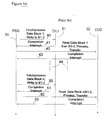
- Figure 1a is a schematic timing diagram used to explain the sequence of operations conducted by the central processor and peripherals in the scheme depicted in Figure 1.
- FIG 1B is used to illustrate that the shared memory data buffer B1-2 of Figure 1 can have plural partitions or sections.
- Figure 2 is a schematic block diagram, similar in format to that in Figure 1 but illustrating the signalling functions of central processor and peripherals in the handling of a data streaming operation in accordance with an embodiment of the present invention.
- Figure 2a is a timing diagram used to explain the sequence of operations performed by processor and peripherals in conducting a data streaming operation in accordance with an embodiment of the present invention.
- Figure 3 is a schematic block diagram illustrating use of a surrogate (or virtual) control unit, emulated in a central processor subsystem, to interface to control units that are not architected for interpreting control information in accordance with the invention (e.g. pre-existing control units); so that a surrogate unit acting in combination with an "unarchitected" control unit appears to function as properly architected control unit (relative to other control units involved in a streaming operation).
- a surrogate (or virtual) control unit emulated in a central processor subsystem, to interface to control units that are not architected for interpreting control information in accordance with the invention (e.g. pre-existing control units); so that a surrogate unit acting in combination with an "unarchitected" control unit appears to function as properly architected control unit (relative to other control units involved in a streaming operation).
- Figure 4 is a schematic block diagram illustrating the functional shifting of a stream processing function from a peripheral device into a virtual device emulated in the central processor subsystem, to have both surrogate control and selected stream processing functions performed in the processor subsystem. This type of arrangement is useful to provide stream processing functions to users of a computer system at potentially less cost (but slower) than could be obtained from devices external to their systems, or to provide stream processing functions that are not implemented in stand-alone devices.
- Figure 5 provides a schematic overview of control information movement and stream data movement, as viewed by a device, and also shows that a single device may concurrently support processing of multiple data streams. This figure is also used to describe how a single data stream may be partitioned into multiple streams or how multiple streams could be merged into a single stream under appropriate circumstances.
- Figure 6 is used to explain how multiple data buffers shared between a communicating pair of stream processing units could be replaced by a single FIFO (first in first out) buffer.
- Figure 7 is used to explain how directly communicating stream processing devices can be adapted to use a private buffer policy to manage storage of stream data passing between them, which can be particularly effective when such devices and their shared buffer reside physically in a single unit.
- FIG 8 summarizes all possible inputs and outputs associated with stream processing in accordance with this invention.
- Figure 9 illustrates the format of an Open Stream Request block that is an element of control information furnished in accordance with this invention.
- Figure 9a shows details of an "open stream parameters" field contained in the Open Stream Request element.
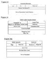
- Figures 10-15 show formats of various descriptor sub-fields that can be contained in an "open stream parameters" field.
- Figure 10 shows a "buffer group descriptor” subfield.
- Figure 11 shows a “buffer descriptor” subfield.
- Figure 12 shows a “buffer notification descriptor” subfield.
- Figure 13 shows an "input signal code descriptor” subfield.
- Figure 14 shows a "synchronization descriptor” subfield.
- Figure 15 shows a "transform descriptor” subfield. Parts and functions of these subfields are given in the detailed description.
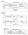
- Figure 16 shows the format of a buffer control request element that is part of the control information furnished in accordance with the invention.
- Figure 16a shows the format of a buffer control parameters field contained in the buffer control request element.
- Figure 17 shows the format of a buffer synchronization control request element that is part of the control information of the invention.
- Figure 17a shows a "synch control parameters" field that is contained in the control element of Figure 17.
- Figure 18 shows the format of a stream control request element in accordance with the invention.
- Figure 18a shows details of the stream control parameters field contained in the request element of Figure 18.
- Figures 19a, 19b, and 19c contain a flow diagram describing the operations and logical organization of a control unit adapted for data streaming in accordance with the present invention.
- Figure 20 is a schematic block diagram illustrating logical components of a control unit operating in accordance with the flow diagram of Figures 19a, 19b, 19c.
- FIG. 1 a schematic of a conventional computer system with multimedia capability -- is used to explain the "interrupt latency" problem solved by the present invention.
- Processor and memory subsystems are shown collectively at 1, and designated Processor/Memory Subsystem (PSS).
- PSS Processor/Memory Subsystem
- a hierarchy of programming entities is used to control movement of data between peripheral devices. These entities may include a device manager subsystem 2, a stream manager subsystem 3, an operating system 4, device drivers 5, 6 associated with specific devices, and “routers” 7 - 8, for routing signals between the PSS subsystem and devices.
- Routers 7 - 8 are useful for routing formatted control information, between subsystems of a computer system, in accordance with Subsystem Control Block (SCB) architecture concepts described in publication "SCB Architecture supplement to the IBM Personal System/2 Hardware Interface Technical Reference Architectures" (Copyright 1991, International Business Machines Corporation) and also in US patent 5325492 by Bonavento et al. US 5325492 describes a command delivery mechanism which may be used as a component of this embodiment.
- SCB architecture varied length control elements with predetermined formats are passed between client and server entities, for defining units of work to be conducted by the server entities.
- the control elements are routed to pipe configurations of enqueued elements, and routers such as those shown here decode destination codes in each element to route the information to appropriate "pipes".
- routers actually may be implemented as a single entity (program module) within a processor subsystem such as PSS.
- An input-output channel links the PSS subsystem to device control units shown generally at 12 which control respective devices.
- Two such control units, 13 and 14, are shown in this figure, along with devices 15 and 16 controlled respectively by unit 13 (CU1) and unit 14 (CU2).
- Channel 10 has a peer communication feature enabling control units such as 13 and 14 to communicate with each other directly (i.e. without intervention of parts of PSS).
- a suitable channel facility with a feature of this kind is the IBM Micro Channel.
- CU1 has an associated router 13a which, when CU1 is sending control elements to pipes in other parts of the system, serves to route such elements to appropriate pipe destinations (e.g. parts of PSS and/or other control units like CU2).
- CU2 has an associated router 14a directing its control element communications to pipes in PSS and in other control units like CU1.
- Devices 15 and 16 are assumed to be involved in an operation involving successive processing of large amounts of data; first by device 15 and then by device 16.
- Data buffer 17 (designated B1-2), shared by these devices, receives data processed by device 15 and supplies the data to device 16.
- buffer B1-2 is contained in the memory subsystem of PSS, but is shown separately in the present drawings for simplicity (B1-2 also could be a dedicated memory buffer,used only by the devices 15 and 16, without necessarily affecting the operation of the present invention).
- channel 10 allows control units and other peripheral equipment to inter-communicate directly.
- bus mastership is assumed alternately by central processor, memory and peripheral subsystems of the computer system.
- peripherals When peripherals have master control of the bus they communicate directly with either the memory subsystem, the processor subsystem or other peripherals.
- the processor controls the bus it communicates usually with peripherals and outlying portions of the memory subsystem.
- the memory subsystem controls the bus, it acts through either a Direct Memory Access (DMA) controller to communicate with devices or through a Memory Controller to communicate with outlying components of the memory subsystem.
- DMA Direct Memory Access
- Figure 1A illustrates conventional handling of data transfer processes involving movement of a large amount of data from device 15/CU1 to B1-2, and from B1-2 to device 16/CU2.
- a large amount of data in the present context is an amount which could exceed the capacity of B1-2 by several orders of magnitude.
- vertical lines 30-32 represent time, increasing progressively in the downward direction, and horizontal lines depict specific actions.
- Horizontal lines emanating from vertical line 30 depict actions originated by PSS.
- Horizontal lines emanating from vertical line 31 depict actions originated by CU1 or device 15.
- Horizontal lines emanating from vertical line 32 depict actions controlled by CU2 or device 16.
- the operation is started by a command from PSS to CU1 and device 15 directing them to fetch a first of n blocks of data from a source designated by the command (which could be in the memory subsystem or in another device such as a CD-ROM), process the block and write the result to shared buffer B1-2.
- a source designated by the command which could be in the memory subsystem or in another device such as a CD-ROM
- CU1 presents a completion interrupt signal to PSS.
- PSS controls the channel to retrieve status information from CU1 and device 15.
- PSS acts at 42 to command CU2 and device 16 to process the data block placed in B1-2. Then CU2 and device 16 perform a respective process and conclude with another completion interrupt signal from CU2 to PSS shown at 43.
- data is read from B1-2, processed, and sent to a destination specified in the command given at 42 (either to another block of shared memory, to a block of unshared memory, or to a specific output device such as a display monitor or loudspeaker).
- PSS recovers associated status information from CU2 and device 16.
- n can be an unknown and very large number, and that the cumulative delays associated with the handling of the (2 times n) completion interrupts in PSS can be very long.
- FIG. 1B shows that B1-2 can have two or more sections.
- CUl's device 15 could be separately filled by CUl's device 15 and emptied by CU2's device 16.
- CUl's device 15 could be separately filled by CUl's device 15 and emptied by CU2's device 16.
- partitioned buffers are subject to concurrent (although not necessarily instantaneously simultaneous) access, for enabling devices such as 15 and 16 realize higher data throughput; i.e. PSS could initiate an action by CU1 relative to B1-2A while CU2 is performing an operation relative to data previously placed in B1-2B. Accordingly, PSS might not have to wait for completion interrupts and status from CU2 before starting the handling of a next data block by CU1.
- the present embodiment seeks to eliminate the delays associated with PSS handling of block completion interrupts, as well as to offload from PSS much of the processing burden associated with its handling of block completion interrupts.
- Figure 2 illustrates a system like that in Figure 1, but which is adapted for handling data streams (large volumes of data) through plural devices more efficiently than the system of Figure 1.
- the signalling paths 56 and 57 which respectively link the host system PSS to device control units CU1 and CU2, are used only to initially prepare the control units for a data streaming operation that they are to handle in coordination, and "autonomously" (i.e. without interrupting or interacting with PSS after the operation is initiated).
- CU1 and CU2 direct operations of respective devices relative to a stream of data with arbitrary length, that data passing "piecemeal" through a shared buffer B1-2 which could not simultaneously hold all of the data.
- the data is processed to conclusion, first by CU1's device 15 and then by CU2's device 16, without interruption of PSS. At the conclusion of the streaming operation, that event and its status are communicated to PSS via an interrupt.
- CU1 and CU2 use the direct/peer communication feature of channel 10 to notify each other of events pertaining to buffer B1-2 (e.g. a section having data available for further processing by device 16, or a section becoming available to received data from device 15, since its previous data has been read and processed by device 16).
- These notification communications can take the form of either formatted control elements transferring from a pipe in CU1 to a pipe in CU 2, or signals which are directed to a specific register in CU2.
- the communications are directed to pipes, they are handled through the routers 13a and 14a. When the communications are signals to registers, these routers may be bypassed.
- CU1 When forwarding control signals to CU2, to indicate filling of portions of B1-2 with data, CU1 (or router 13a) assumes master control of the bus containing channel 10 and either directly writes control signals to a register in CU2 or routes a formatted control element to a pipe in CU2 via router 14a.
- Figure 2A like Figure 1A, uses vertical lines to represent time and horizontal lines emanating from the vertical lines to indicate actions performed by PSS and each of the control units.
- PSS provides one or more commands to CU1 to prepare the latter for a streaming operation and to define the operation (buffer spaces to be used in the memory subsystem as a shared data buffer), source of data to be retrieved and processed by device 15, etc.
- PSS receives interruption status from CU1 indicating either that CU1 is ready to begin the streaming operation or was unable to complete its preparation.
- PSS directs one or more commands to CU2 to prepare it for the same streaming operation and to define the operation (buffer space to be used as B1-2, destination of data processed by device 16, etc.).
- PSS receives interruption status from CU2 indicating the latter's status (ready or unprepared).
- control units If other control units are involved in the streaming operation, they too will receive setup instructions from PSS and signal readiness status via interrupts to PSS. If any interruption status returned to PSS indicates that a control unit is unable to complete preparation for the streaming operation, the setup process is aborted and the streaming operation is not started.
- the commands used to set up each control unit may be provided to the control units via the pipe signalling technology disclosed in the application by F. Bonavento et al cross-referenced earlier.
- PSS provides a GO signal at 74 to initiate the streaming operation.
- This signal is provided only to the control unit or units which are required to perform the first actions in the streaming operation; in this case, the signal is given to CU1 whose device 15 will be required to begin fetching data blocks from a designated source, process the data and write result data to B1-2 for further handling by device 16 associated with CU2.
- Actions occurring successively, in processing the first 6 blocks of data in the streaming operation are suggested by horizontal lines 80 through 85; and subsequent actions relative to additional data blocks are suggested by broken vertical line 86.
- shared memory buffer B1-2 contains plural block storage sections B1-2A, B1-2B, etc. (see Figure 1B).
- CU1 signals CU2 to indicate availability of a first block of data in portion B1-2A of shared memory buffer B1-2 (it being understood that prior to this signal device 15 associated with CU1 has processed a corresponding first block of data and written the result block to B1-2A)
- CU1 signals availability of a second block of data in portion B1-2B of B1-2 (with the implication that prior to this signal such data has been written to B1-2B by device 15).
- CU1 signals availability of third, fourth, ..., blocks of data alternately in B1-2A and B1-2B.
- the signals given at 80-86 may be conveyed either in the pipe form taught in the cross-referenced application by F. Bonavento et al or as direct signals( instantly decoded by CU2), depending upon time constraints on the actions required to be performed by CU2 and its device 16.
- CU2 is responsible for controlling device 16 to read the associated block of data from the designated portion of B1-2, process it and transmit the result data to a destination defined in the initial preparation of CU2.
- CU2 may be required to return signals to CU1 as each portion of B1-2 is emptied by actions of device 16.
- CU1, CU2 and respective devices act autonomously (without interrupting PSS or receiving further guidance or control from that system).
- CU After a last data block has been processed by device 15 (which may be determined by that device from signals appended to the end of that block at the source or from a count function provided at initial preparation of CU1, etc.) CU provides a completion interrupt signal to PSS (action 87), enabling PSS to subsequently recover completion status from CU1 and device 15 as well as from CU2 and device 16.
- CU2 may be required to provide a separate completion interrupt to PSS when its device 16 concludes its assigned operations.
- control units participating in the streaming actions described must be logically equipped to be set up by a host system PSS, and, after initiation of at least a first device by that system, such units must be adapted to carry out the signalling functions required relative to other control units cooperating in the streaming process without further input from the host system.
- PSS host system
- users lacking such device control units may desire to have their functions emulated in the host system.
- Figure 3 illustrates this point.
- Device control units 90, 91, and 92, along with respective routers 90a, 91a and 92a, and devices 90b, 91b and 92b, are supposed to be sequentially involved in a streaming operation.
- devices 90b and 91b will share memory data buffer 93 (B1-2)
- devices 91b and 92ba will share memory data buffer 94 (B2-3).
- control unit 91 lacks the logical capabilities for interpreting setup commands furnished by PSS, and of acting autonomously relative to the other two control units in respect to the streaming process per se.
- a simulated or surrogate control unit 95 provided as a program module in PSS, would receive initial setup commands from PSS, and cooperate with control units 90, 91 and 92 to carry out the autonomous control aspects of the streaming operation that control unit 91 itself is unable to perform.
- control units 90 and 92 receive appropriate setup commands and return readiness indications via respective signal paths 96 and 97; and surrogate control unit 95 receives its commands and returns a readiness indication via the path 98.
- surrogate control unit 95 receives its commands by a process that is wholly internal to the PSS complex, determines its "readiness" by communicating with control unit 91, router 91a, and device 91b through the channel, and then reports its readiness status by an interruption process wholly internal to the PSS complex. In determining readiness, surrogate unit 95 communicates with control unit 91 via signal path 99 and channel 10.
- PSS initiates the streaming operation by means of a GO signal to the first control unit 90 (CU1) and device 90b begins processing blocks of data fetched from a designated source and writing result data to portions of buffer B1-2.
- control unit 90 issues a DATA AVAILABLE communication (see Figure 2A) to notify surrogate control unit 95 of this event.
- the notification is in the form of a formatted SCB element that is directed by router 90a to a pipe in PSS which is assigned to surrogate control unit 95; i.e. the information in this notification is conveyed over signal path 100 to surrogate control unit 95.
- surrogate control unit 95 communicates with control unit 91 to set up a conventional command in the latter for having device 91b process a block of data in a specified respective portion of buffer 93, and transfer result data to a specific portion of buffer 94 that is shared by devices 91b and 92ba.
- control unit 95 receives a completion indication from control unit 91 via path 99 (via an interrupt or direct signalling process), and immediately presents a DATA AVAILABLE signal to control unit 92, via path 101 through channel 10.
- the last mentioned signal causes control unit 92 to initiate processing of the respective data block in the autonomous manner described previously.
- Figure 4 illustrates how the arrangement of Figure 3 can be further modified to shift all device and device control functions associated with one device into a virtual device/control unit program element of PSS.
- control unit 91 is wholly integrated into the surrogate controller shown as element 95 in Figure 3 (i.e. in Figure 4, the entire control unit 91 is implemented as software routines executable in PSS), and device 91a in Figure 4 is also implemented entirely by routines executable in PSS.
- control unit 91 and device 91a are conducted as internal functions of PSS (they do not go through the channel 10) and the program modules representing unit 91 can be organized for fully autonomous streaming operation (i.e. it communicates only with units 90 and 92 during a streaming operation and need not furnish status to e.g. the streaming manager in PSS until the entire operation is completed (or aborted).
- Figure 5 provides an overview of control signal and data movement as viewed by a single device and device control unit.
- this figure shows that one control unit and device can be used to sustain multiple streaming operations concurrently.
- several streams could be combined into one stream, or one stream could be broken up into several streams depending upon the processing functions performed by the device relative to such streams.
- Device controller 120 interacts with data buffer management facility 121 to control one or more devices 122 for processing three data streams identified as streams 1-3 in the figure. Data contained in these streams is transferred to the device 122 from input buffers 124-126 that may be part of PSS memory, and that may be shared between device 122 and an "upstream” device that writes the data to the buffers. Data resulting from operations of device 122 are written to output buffers 127-129 that may be shared with a "downstream" device required to handle the data generated by device 122.
- stream 1 passes through input buffer 124 and output buffer 127; stream 2 passes through input buffer 125 and output buffer 128; and stream 3 passes through input buffer 126 and output buffer 129.
- controller 120 is of course prepared by setup command information received from PSS. Controller 120 also receives input control functions at 130, from not-shown upstream control unit(s), and supplies output control functions at 131 to not-shown downstream control unit(s).
- the set up commands may be formatted in accordance with the now-published subsystem control block (SCB) architecture mentioned earlier; and these commands typically would include at least commands to "open” a stream (i.e. prepare for a new streaming operation), commands to "suspend” or “stop” a stream (e.g. to allow for a user to interject a pause in or completely halt a motion picture presentation), and commands to "resume” a previously suspended or stopped stream operation.
- SCB subsystem control block
- the controller 120 and facility 121 may be integral parts of a single control unit or device adapter entity.
- Communications between the illustrated arrangement and control units upstream and downstream of that arrangement are carried out in a manner such that the upstream and downstream units are unaware that they may be communicating with virtual devices implemented in host system routines.
- Figure 6 shows that the buffer shared by two devices, devices A and B respectively shown at 138 and 139, may be a FIFO (first in first out) memory arrangement as suggested at 140.
- An advantage of this type of arrangement is that it eliminates the need for passage of control information between the controller of source device A and the controller of destination device B; inasmuch as control is implicit in this kind of arrangement (i.e. it is assumed that the buffer is always capable of receiving data, and therefore device B is required to process data (in first in first out sequence) whenever the buffer is not explicitly empty.
- a disadvantage is that the buffer could be overrun without the source device or its controller receiving any indication of that occurrence.
- the FIFO arrangement could be viewed as a species of the buffers described in earlier figures, wherein the buffer is one unit in length (the width of the FIFO) and effectively wraps to itself. If the data transfers to the FIFO occur in bursts with automatic address incrementing, special care must be taken to ensure that enough capacity and continuity of addressing is provided in the FIFO to avoid the possibility of addressing memory not part of the shared buffer.
- Figure 7 shows source and destination devices A and B, at 144 and 145 respectively, sharing a private buffer 146; typically a buffer not allocatable to other devices and preferably a buffer so situated that data is communicated between it and the devices without crossing the channel (reference channel 10, Fig. 2).
- the devices have a "private" permanent understanding or protocol in regard to the order in which segments or block portions of the buffer are filled and emptied, so that there is no need for passage of control information from source to destination in order to indicate the location of the portion most recently filled.
- Figure 8 provides a summary view of all possible inputs and outputs (control and data) described in previous sections. Types of possible input and output buffers are indicated respectively at 148 and 149. In order to ensure proper movement of data between devices sharing a buffer a "lowest common denominator" must be agreed to and architected for all devices and associated control units.
- a likely choice for buffer configuration would be a simple buffer, in shared system memory, having two portions that are utilized in a "ping pong” fashion (i.e. the source filling the sections alternately and the destination reading them in the same sequence).
- the decision as to which type of buffer to use and the type of control information that should be passed between source and destination should be made by the Stream Manager using information available to the system when devices are attached to it as to the capabilities of the devices and their control units.
- Request control elements are one species of SCB architected forms. Other control elements are reply type elements, event type elements and error type elements. Requests are sent from a client/source to a server/destination defining performance of a unit of work. Replies are returned by servers in response to certain types of requests. Event (notification) elements furnish information about the progress of requested work, the state of a request, or the status of a client or server. Error type elements provide error information about requests or about status of a server.
- Request elements are used presently to set up streaming operations, and event elements may be used presently in notification communications that pass between control units during the performance of streaming operations.
- the requests employed presently to set up streaming are labelled: OPEN STREAM, CONTROL, BUFFER CONTROL, and BUFFER SYNCHRONIZATION CONTROL.
- the OPEN STREAM request format is shown in Figures 9 and 9a, and formats of descriptor information furnished with this request are shown in Figures 10-15.
- the BUFFER CONTROL request format is shown in Figures 16 and 16a.
- the BUFFER SYNCHRONIZATION CONTROL request format is shown in Figures 17 and 17a.
- the STREAM CONTROL request format is shown in Figures 18 and 18a.
- FIG. 9 The format of an OPEN STREAM request control element is shown in Figures 9 and 9a.
- This request contains a number of information fields 160-167 described below.
- Field 160 - contains format identity (Format ID) information serving to identify the type of control element.
- Field 161 - contains length information defining the length of the request in bytes.
- Field 162 - contains eight discrete subfields: REQ (Request) - defines the type of control element (in this case, a request type); S ("suppress reply") - is a bit indicating whether the client wants the server to return a reply at successful completion of requested work; C (“chaining") - a bit indicating a chaining linkage between two or more control elements which represent a single unit of work to be processed in the order of their appearance; I (“indirect”) - a bit (valid only in request type control elements) for indicating whether the parameters (or value) field discussed below contains a direct representation of information to be interpreted or pointers to memory locations of such information; N (“notification bit”) - (valid only in request elements) indicating whether the client has or has not requested notification by the server when processing of the respective request element begins; W (“wait”) - bit (valid only in request type elements) indicating if the server is to wait, before processing the respective control element, until the client furnishes a specific "resume” notification; E (“ex
- Field 164 - defines the source of the command associated with this request (e.g. the client).
- Field 165 - defines the destination of the request (i.e. the pipe or other server entity to which the request is to be routed).
- Field 166 - contains a correlation field used for correlating request and reply control elements.
- Field 167 - is a variable length parameters (also called "values") field, containing a variable number of descriptors. The descriptors are used presently to define:
- Each descriptor contains sub-fields 169-172 used as follows: Subfield 169 - contains information defining the descriptor type (see discussions of Figures 10-15 to follow); Subfield 170 - contains information defining the length of the respective descriptor (e.g. in bytes); Subfield 171 - is reserved; Subfield 172 - contains the descriptor information (the information specific to and dependent on the respective descriptor).
- the type and length subfields are unique for different types of descriptors.
- the number of descriptors in any OPEN STREAM request is variable (depends on the number of buffers defined, the number of notifications required for each buffer fill/empty event, and the type of signalling to be used for notification).
- a Buffer Group descriptor shown in Figure 10
- a Buffer descriptor Figure 11
- a Buffer Notification descriptor Figure 12
- an Input Signal Code descriptor Figure 13
- a Synchronization descriptor Figure 14
- a Transform descriptor Figure 15
- the Buffer Group descriptor ( Figure 10) is used to define a group of buffers which are to be used and managed collectively as a shared input or output buffer (each single buffer or group component part serving e.g. to hold a block of data, and the parts collectively being filled or emptied in some predetermined order).
- the information fields contained in this type of descriptor are: Byte 0-1: x'010C' (the code identifying this type of descriptor); Byte 2-3: reserved; Byte 4-5: identity (ID) of a respective Buffer Group; Byte 6-7: reserved; Byte 8: number of buffers in the group; Byte 9: flags for: Input/Output control Buffer Management Policy (Circular, FIFO, private, etc.) error reporting policies; error recovery policies; Byte 10: Relative Stream Priority (the processing priority of a stream flowing through this buffer group over other streams); Byte 11: Reserved.
- the Buffer descriptor ( Figure 11) is used to define a Buffer that is a component part of a Buffer Group.
- This descriptor contains: Byte 0-1: x'0214' (the code value specific to this type descriptor); Byte 2-3: reserved Byte 4-5: Buffer Group ID (see above); Byte 6-7: Buffer ID (identity of the particular buffer described in this descriptor); Byte 8-11: buffer address (32 bits defining an initial location for this buffer in the memory address space of the system); Byte 12-15: buffer length (in bytes); Byte 16: Flags for: Input/Output control; Notification buffer full (output buffer only); Wait for buffer to empty (output buffer only); Notification buffer empty (input only); Wait for buffer to fill (input only); Byte 17-19: reserved
- the Buffer Notification descriptor ( Figure 12) defines which devices to notify when a buffer reaches a boundary condition (full, representing data available to be processed, or empty, representing that all data in the buffer has been processed). Elements of this descriptor are: Byte 0-1: x'030C' (the code uniquely identifying this type of descriptor); Byte 2-3: reserved; Byte 4-5: Buffer Group ID; Byte 6-7: Buffer ID; Byte 8-9: Flags for: Bit 0 - all buffers/Buff ID only (indication that notification should occur for all buffers in the group as opposed to only a single particular buffer in a group); Bit 1 - Signal/Event (indicates if notification should be in the form of a signal (e.g.
- Bit 10 indicates a Signal Code to be used when notifying the other unit via a directed signal; or, the unit address (destination) to use to send an event if Bit 1 is set to "event".
- I/O Port Address the address in system I/O space of the specific register or other entity to which a notification signal is to be directed, when such signalling is applicable
- entity address destination
- the Input Signal Code descriptor ( Figure 13) defines the signal codes that are to be received by the device to which the descriptor is directed.
- the contents of this descriptor are: Byte 0-1: x'040C' (the code value uniquely identifying this type of descriptor); Byte 2-3: reserved; Byte 4-5: Buffer Group ID; Byte 6-7: Buffer ID; Byte 8: Flags for: Bit 0 - all buffers ID only (see previous definition of this); Bit 1 - to indicate Output Buffer empty; Bit 2 - to indicate Input Buffer full; Byte 9: reserved; Byte 10: Signal Code (for indicating a signal code to be used for direct signalling notification, when applicable); Byte 11: I/O Port Address( in system I/O address space of register or other entity to receive a signal notification, when applicable).
- the Synchronization descriptor ( Figure 14) defines how the respective Buffer Group of the targeted device is to be synchronized with other streams (e.g. how a Buffer Group processing a video stream is to be synchronized with the separate handling of an audio stream) or timers.
- the Transform descriptor ( Figure 15) defines the relationship between input and output data to be handled by the device to which the descriptor is directed (i.e. the process, if any, to be performed by the device on the input data it receives).
- the change relative to similarly formatted control elements of other descriptors is to allow source and destination addresses in this area to specify a Buffer Group ID, rather than a memory address representing the physical location of a shared buffer.
- the Buffer Control Request element ( Figures 16 and 16a) is used in request, reply and error control. It contains the parameters needed to control filling and emptying of buffers within a Buffer Group. Component fields of this request are indicated in Figure 16, and component subfields of the "Parameters" field of this request are shown in Figure 16a.
- the fields other than the "BufferControl” and “Parameters” field in this request have functions, and Positions within the request that are substantially identical to those of correspondingly labelled fields in the OPEN STREAM request ( Figure 9).
- the "Buffer Control” field contains a code which distinguishes the request as being a Buffer Control type request.
- the "Parameters" field in the Buffer Control Request contains the following information: Byte 0-1: Buffer Group ID; Byte 2-3: Buffer ID; Byte 4: Flags: Bit 0 - indicating Output Buffer empty; Bit 1 - indicating Input Buffer full; Bit 2 - indicating Output Buffer error (recoverable); Bit 3 - indicating Output Buffer error (non-recoverable); Bit 4 - indicating Input Buffer error (recoverable); Bit 5 - indicating Input Buffer error (nonrecoverable); Byte 5-7: reserved; Byte 8-11: Error Code (Bit 0 distinguishing between recoverable and non- recoverable errors); Byte 12-15: Residual Byte Count (for indicating the amount of data yet to be processed as a result of an error); only valid in error conditions and should have a zero value during normal operations; Byte 16: device dependent (for indicating e.g., additional status, error or other).
- the Buffer Sychronisation Control request element (shown in Figures 17 and 17a), like the Buffer Control request element described in the preceding section, is used in request, reply and error control situations. It contains all information needed to control synchronization of buffers within a Buffer Group. Component fields of this request are shown in Figure 17, and subfields of the respective Parameters component field are shown in Figure 17a. Except for the fields labelled "SyncControl” and "Parameters", all other component fields of the Buffer Synchronization Control Request, are essentially identical to correspondingly labelled (and positioned) fields in the OPEN STREAM and Buffer Control requests. The field labelled "SyncControl" contains a code distinguishing this request as a Buffer Synchronization Control type request.
- the component subfields of the Parameters field, in the Buffer Synchronization Control Request are: Byte 0-1: Buffer Group ID; Byte 2-3: reserved; Byte 4: Flags for: indicating sync to timer; indicating sync to stream per se; indicating sync to consumption/delivery rate specified in byte 5; Byte 5: consumption/delivery rate; Byte 6-7: reserved; Byte 8-11: Timer address or Stream Correlation ID.
- the Stream Control Request is also used in request, reply and error control situations. It contains information needed to control stream processing. Component fields of this request ( Figure 18), other than the respective fields labelled “StreamControl” and “Parameters”, are identical to correspondingly labelled fields in the other requests described above.
- the field labelled "StreamControl” contains a code distinguishing the request as a Stream Control type request.
- Figures 19a, 19b, and 19c contain parts of a flow diagram intended to describe the logical organization of device control units that are adapted in accordance with the invention for carrying out streaming processes.
- Figure 20 is a block diagram intended to show logical elements needed for streaming in a broad "means plus function" context.
- the setup phase of the streaming process is shown in Figure 19a.
- the control unit receives requests and descriptors of the type described above, and sets itself to a working configuration defined by these functions.
- the working configuration includes parameters defining the buffer policies required relative to input data and output data, synchronization policies if required, and notification policies; and conditioning of logic in the control unit to conform to policies defined by these parameters.
- the control unit conditions its logic to operate with an input buffer group having a variable number of buffers defined by value P max , and with an output buffer group having a variable number of buffers defined by value Q max .
- the number of buffers in each group i.e., the values of P max and Q max ), and sizes of individual buffers in each group, are defined by information contained in the descriptors received at stage 240.
- the subscript "max” is a value defining the number of buffers allocated by PSS for each group. It is not meant to connote a "maximum” in the context of for instance defining an upper limit on the number of buffers which could be allocated to a group (although practical circumstances may impose such a limitation on PSS).
- control unit sets values of counting functions P and Q, which respectively point to the next input buffer to be processed and the next output buffer to be filled, to initial values 1 (effectively pointing to specific "first" buffers in the input and output buffer groups).
- the control unit Before advancing to the decision function shown at 243, the control unit signals its status to the processor system (PSS) via interruption. If this status indicates that the control unit is unable to proceed due to error, the process of preparing and initiating the streaming operation is discontinued by PSS (see earlier comments, in the description of Figure 2A, regarding how status interruptions affect initiation of the streaming operation).
- PSS processor system
- the control unit determines if the signal to begin stream processing has been received from its host system PSS (e.g. the GO signal from PSS mentioned earlier, or its equivalent in a request calling for immediate resumption of a suspended stream processing operation). When that signal is received, the process advances to the segment shown in Figure 19b (via link "circled a"); and if the signal has not been received the unit waits a Predetermined time (step 244) and repeats determination 243.
- PSS host system
- control unit determines first, at 245, if the source of input data for its device is an Input Buffer shared with another (upstream) device or a specific other device (such as CD-ROM, tape, hard disk, network port, etc.).
- the respective device is prompted, at 246, to read data from the specific source device.
- the determination at 245 is that the source of input data is an input buffer (i.e. a buffer shared with an upstream device)
- determination 250 If the input buffer is not available at determination 250, that determination is repeated after a predetermined wait time. If the input buffer contains available data, determination 251 is made to determine if the data in the buffer needs process/transformation handling or simple buffered handling.
- the device is prompted to perform a respective process (defined in the set up requests) at 252, and the segment continues with further actions 253 and 254. If the determination at 251 is that no transformational processing is needed, action 252 is skipped and the segment advances directly to actions 253 and 254.
- the current state of the input buffer e.g. buffer "empty” or available for refilling
- determination 260 is made to determine the destination of data produced in the segment of Figure 19b; as either a (shared) Output Buffer or a specific device (monitor, loudspeaker, etc.).
- action 261 is taken, to forward the data to that device, followed by selected parts of an action routine indicated at 262 to 267 (explained below), and, when all of the output data has been handled in this manner, followed by re-entry to action stage 243 in the setup segment of Figure 19a, via the "circled b" linkage.
- action 270 is performed to write the data to that buffer. This is followed by actions 271 and 272 leading to the actions 262 to 267 mentioned above.
- action 271 a determination is made as to whether any parties require notification. If notification is required, action 272 is performed to accomplish the notification. If notification is not required action 272 is skipped and the segment advances directly to action set 262 to 267.
- the value of the count function P. designating the Input Buffer from which data is currently being read is compared to the maximum value P max established in actions 241 (Fig. 19a). If the value of P is less than that of P max , the value of P is incremented by 1 (action 263). If the value of P is equal to P max , the value of P is reset to 1 (action 264) to begin reading data from the first input buffer again.
- the value of Q designating the Output Buffer currently being filled, is compared to the value Q max defining the total number of output buffers currently being used. If Q is less than Q max , Q is incremented by 1 (action 266). if Q is equal to Q max , Q is reset to the value 1 to begin the refilling of the first output buffer.
- Actions requiring notification of other parties are conducted through the channel 10 ( Figure 1).
- the notification information may be formed as directly interpreted signals placed in an addressable register (in the control unit being notified), via the peer communication feature of the channel, or it may be formed as an SCB event control element (recall earlier discussion) which is sent to a pipe feeding another control unit.
- the pipe itself can be located in a buffer (separate from the shared data buffers) in system/PSS memory or in a buffer memory integral to the other control unit that it feeds.
- the router in (or associated with) the control unit initiating the action and determines the physical route for the communication (system memory route or peer communication route to an address in an integral buffer).
- Figure 20 indicates the logical organization of a control unit (for autonomous stream processing in accordance with this invention) in terms of means provided for accomplishing the functions effectively described in Figures 19a-19c.
- control unit requires means to receive from PSS the request elements defining the streaming process.
- control unit requires means responsive to the request elements furnished during setup to prepare the respective unit for the streaming operation (establish register conditions needed for the operation, test availability of paths to specified input and output buffers, etc.).
- Means shown at 292 enables the control unit to indicate its readiness or error state to PSS.
- Means shown at 293 is conditioned logically by the initiating signal from the host (GO signal or stream control request with immediate resume function), and the conditions established during setup, to start and continue the streaming process in an autonomous manner (i.e. potentially without further input from the host system PSS until all of the data to be processed has been processed).
- this last means includes means for carrying out notification functions specified in Notification type descriptors.
Applications Claiming Priority (2)
| Application Number | Priority Date | Filing Date | Title |
|---|---|---|---|
| US282993 | 1994-07-29 | ||
| US08/282,993 US5568614A (en) | 1994-07-29 | 1994-07-29 | Data streaming between peer subsystems of a computer system |
Publications (2)
| Publication Number | Publication Date |
|---|---|
| EP0694847A2 true EP0694847A2 (de) | 1996-01-31 |
| EP0694847A3 EP0694847A3 (de) | 1999-08-04 |
Family
ID=23084023
Family Applications (1)
| Application Number | Title | Priority Date | Filing Date |
|---|---|---|---|
| EP95305073A Withdrawn EP0694847A3 (de) | 1994-07-29 | 1995-07-20 | Datenströmung in einem Rechnersystem |
Country Status (5)
| Country | Link |
|---|---|
| US (1) | US5568614A (de) |
| EP (1) | EP0694847A3 (de) |
| JP (1) | JP3251815B2 (de) |
| KR (1) | KR0163234B1 (de) |
| CA (1) | CA2152984A1 (de) |
Cited By (8)
| Publication number | Priority date | Publication date | Assignee | Title |
|---|---|---|---|---|
| WO2003052586A2 (en) * | 2001-12-14 | 2003-06-26 | Koninklijke Philips Electronics N.V. | Data processing system having multiple processors |
| WO2003052587A2 (en) * | 2001-12-14 | 2003-06-26 | Koninklijke Philips Electronics N.V. | Data processing system |
| WO2004042574A2 (en) * | 2002-10-31 | 2004-05-21 | Lockheed Martin Corporation | Computing machine having improved computing architecture and related system and method |
| GB2410578A (en) * | 2004-02-02 | 2005-08-03 | Surfkitchen Inc | Routing system for routing data and commands in a mobile phone |
| FR2866729A1 (fr) * | 2004-02-25 | 2005-08-26 | Opencube | Dispositif a memoire virtuelle partagee auto-administree apte a gerer au moins un flux de donnees multipiste |
| WO2005093570A1 (fr) * | 2004-02-25 | 2005-10-06 | Opencube Technologies | Dispositif a memoire virtuelle partagee auto-administree apte a gerer au moins un flux de donnees multipiste |
| US7373432B2 (en) | 2002-10-31 | 2008-05-13 | Lockheed Martin | Programmable circuit and related computing machine and method |
| US7487302B2 (en) | 2004-10-01 | 2009-02-03 | Lockheed Martin Corporation | Service layer architecture for memory access system and method |
Families Citing this family (106)
| Publication number | Priority date | Publication date | Assignee | Title |
|---|---|---|---|---|
| US7349976B1 (en) * | 1994-11-30 | 2008-03-25 | Realnetworks, Inc. | Audio-on-demand communication system |
| US5793980A (en) | 1994-11-30 | 1998-08-11 | Realnetworks, Inc. | Audio-on-demand communication system |
| US6311265B1 (en) | 1996-03-25 | 2001-10-30 | Torrent Systems, Inc. | Apparatuses and methods for programming parallel computers |
| US6199152B1 (en) | 1996-08-22 | 2001-03-06 | Transmeta Corporation | Translated memory protection apparatus for an advanced microprocessor |
| US5848367A (en) * | 1996-09-13 | 1998-12-08 | Sony Corporation | System and method for sharing a non-volatile memory element as a boot device |
| US6330008B1 (en) * | 1997-02-24 | 2001-12-11 | Torrent Systems, Inc. | Apparatuses and methods for monitoring performance of parallel computing |
| US6020900A (en) * | 1997-04-14 | 2000-02-01 | International Business Machines Corporation | Video capture method |
| US6088716A (en) * | 1997-04-28 | 2000-07-11 | Ab Initio Software Corporation | Method for preventing buffer deadlock in dataflow computations |
| US8621101B1 (en) | 2000-09-29 | 2013-12-31 | Alacritech, Inc. | Intelligent network storage interface device |
| WO1999023762A1 (en) * | 1997-11-03 | 1999-05-14 | Harris Corporation | Reconfigurable radio system architecture |
| US6430652B1 (en) | 1997-12-30 | 2002-08-06 | Lsi Logic Corporation | Method and apparatus for streaming data in a data processing system |
| US6298409B1 (en) * | 1998-03-26 | 2001-10-02 | Micron Technology, Inc. | System for data and interrupt posting for computer devices |
| US20030120775A1 (en) * | 1998-06-15 | 2003-06-26 | Compaq Computer Corporation | Method and apparatus for sending address in the message for an e-mail notification action to facilitate remote management of network devices |
| US6219730B1 (en) * | 1998-06-20 | 2001-04-17 | Nghi Nho Nguyen | Method and apparatus for producing a combined data stream and recovering therefrom the respective user input stream and at least one additional input signal |
| CN1867068A (zh) | 1998-07-14 | 2006-11-22 | 联合视频制品公司 | 交互式电视节目导视系统及其方法 |
| US6132520A (en) | 1998-07-30 | 2000-10-17 | Howmet Research Corporation | Removal of thermal barrier coatings |
| US6307487B1 (en) | 1998-09-23 | 2001-10-23 | Digital Fountain, Inc. | Information additive code generator and decoder for communication systems |
| US7068729B2 (en) | 2001-12-21 | 2006-06-27 | Digital Fountain, Inc. | Multi-stage code generator and decoder for communication systems |
| US6651074B1 (en) * | 1999-12-20 | 2003-11-18 | Emc Corporation | Method and apparatus for storage and retrieval of very large databases using a direct pipe |
| US6968469B1 (en) | 2000-06-16 | 2005-11-22 | Transmeta Corporation | System and method for preserving internal processor context when the processor is powered down and restoring the internal processor context when processor is restored |
| US7103906B1 (en) | 2000-09-29 | 2006-09-05 | International Business Machines Corporation | User controlled multi-device media-on-demand system |
| US8019901B2 (en) | 2000-09-29 | 2011-09-13 | Alacritech, Inc. | Intelligent network storage interface system |
| KR20190096450A (ko) | 2000-10-11 | 2019-08-19 | 로비 가이드스, 인크. | 매체 콘텐츠 배달 시스템 및 방법 |
| US20020073238A1 (en) * | 2000-11-28 | 2002-06-13 | Eli Doron | System and method for media stream adaptation |
| US6622222B2 (en) * | 2001-04-26 | 2003-09-16 | International Business Machines Corporation | Sequencing data on a shared data bus via a memory buffer to prevent data overlap during multiple memory read operations |
| KR100593320B1 (ko) * | 2001-06-19 | 2006-06-26 | 박장현 | 스트리밍 버퍼를 이용한 인터넷 원격조작 시스템 |
| KR20030018141A (ko) * | 2001-08-27 | 2003-03-06 | 주식회사 엘지이아이 | 스트림 데이터 처리시스템 및 그 방법 |
| US7249291B2 (en) * | 2002-02-15 | 2007-07-24 | Digital Fountain, Inc. | System and method for reliably communicating the content of a live data stream |
| US9240810B2 (en) | 2002-06-11 | 2016-01-19 | Digital Fountain, Inc. | Systems and processes for decoding chain reaction codes through inactivation |
| US7154886B2 (en) | 2002-07-22 | 2006-12-26 | Qlogic Corporation | Method and system for primary blade selection in a multi-module fiber channel switch |
| US7397768B1 (en) | 2002-09-11 | 2008-07-08 | Qlogic, Corporation | Zone management in a multi-module fibre channel switch |
| KR101143282B1 (ko) | 2002-10-05 | 2012-05-08 | 디지털 파운튼, 인크. | 연쇄 반응 코드의 체계적 인코딩 및 디코딩 |
| US7319669B1 (en) | 2002-11-22 | 2008-01-15 | Qlogic, Corporation | Method and system for controlling packet flow in networks |
| JP2004180092A (ja) * | 2002-11-28 | 2004-06-24 | Sony Corp | 情報処理装置および情報処理方法、並びにコンピュータ・プログラム |
| US7493646B2 (en) | 2003-01-30 | 2009-02-17 | United Video Properties, Inc. | Interactive television systems with digital video recording and adjustable reminders |
| US6961784B1 (en) * | 2003-04-17 | 2005-11-01 | Qlogic Corporation | Method and system for processing non-data frames in host bus adapters |
| US7471635B2 (en) | 2003-07-16 | 2008-12-30 | Qlogic, Corporation | Method and apparatus for test pattern generation |
| US7388843B2 (en) | 2003-07-16 | 2008-06-17 | Qlogic, Corporation | Method and apparatus for testing loop pathway integrity in a fibre channel arbitrated loop |
| US7453802B2 (en) | 2003-07-16 | 2008-11-18 | Qlogic, Corporation | Method and apparatus for detecting and removing orphaned primitives in a fibre channel network |
| US7463646B2 (en) | 2003-07-16 | 2008-12-09 | Qlogic Corporation | Method and system for fibre channel arbitrated loop acceleration |
| US7152132B2 (en) * | 2003-07-16 | 2006-12-19 | Qlogic Corporation | Method and apparatus for improving buffer utilization in communication networks |
| US7522522B2 (en) | 2003-07-21 | 2009-04-21 | Qlogic, Corporation | Method and system for reducing latency and congestion in fibre channel switches |
| US7894348B2 (en) | 2003-07-21 | 2011-02-22 | Qlogic, Corporation | Method and system for congestion control in a fibre channel switch |
| US7684401B2 (en) | 2003-07-21 | 2010-03-23 | Qlogic, Corporation | Method and system for using extended fabric features with fibre channel switch elements |
| US7646767B2 (en) | 2003-07-21 | 2010-01-12 | Qlogic, Corporation | Method and system for programmable data dependant network routing |
| US7630384B2 (en) | 2003-07-21 | 2009-12-08 | Qlogic, Corporation | Method and system for distributing credit in fibre channel systems |
| US7234101B1 (en) | 2003-08-27 | 2007-06-19 | Qlogic, Corporation | Method and system for providing data integrity in storage systems |
| CN101834610B (zh) | 2003-10-06 | 2013-01-30 | 数字方敦股份有限公司 | 通过通信信道接收从源发射的数据的方法和装置 |
| US7219263B1 (en) | 2003-10-29 | 2007-05-15 | Qlogic, Corporation | Method and system for minimizing memory corruption |
| US7930377B2 (en) | 2004-04-23 | 2011-04-19 | Qlogic, Corporation | Method and system for using boot servers in networks |
| KR101205758B1 (ko) | 2004-05-07 | 2012-12-03 | 디지털 파운튼, 인크. | 파일 다운로드 및 스트리밍 시스템 |
| US7669190B2 (en) | 2004-05-18 | 2010-02-23 | Qlogic, Corporation | Method and system for efficiently recording processor events in host bus adapters |
| US7577772B2 (en) * | 2004-09-08 | 2009-08-18 | Qlogic, Corporation | Method and system for optimizing DMA channel selection |
| US20060064531A1 (en) * | 2004-09-23 | 2006-03-23 | Alston Jerald K | Method and system for optimizing data transfer in networks |
| US7380030B2 (en) | 2004-10-01 | 2008-05-27 | Qlogic, Corp. | Method and system for using an in-line credit extender with a host bus adapter |
| US7676611B2 (en) | 2004-10-01 | 2010-03-09 | Qlogic, Corporation | Method and system for processing out of orders frames |
| US7398335B2 (en) * | 2004-11-22 | 2008-07-08 | Qlogic, Corporation | Method and system for DMA optimization in host bus adapters |
| US7164425B2 (en) * | 2004-12-21 | 2007-01-16 | Qlogic Corporation | Method and system for high speed network application |
| US8015306B2 (en) * | 2005-01-05 | 2011-09-06 | Control4 Corporation | Method and apparatus for synchronizing playback of streaming media in multiple output devices |
| US7392437B2 (en) | 2005-01-20 | 2008-06-24 | Qlogic, Corporation | Method and system for testing host bus adapters |
| US7231480B2 (en) * | 2005-04-06 | 2007-06-12 | Qlogic, Corporation | Method and system for receiver detection in PCI-Express devices |
| US7281077B2 (en) * | 2005-04-06 | 2007-10-09 | Qlogic, Corporation | Elastic buffer module for PCI express devices |
| US7716359B2 (en) * | 2005-05-09 | 2010-05-11 | Microsoft Corporation | Method and system for providing an interface through which an application can access a media stack |
| US20070011287A1 (en) * | 2005-05-16 | 2007-01-11 | Charbel Khawand | Systems and methods for seamless handover in a streaming data application |
| US20070073965A1 (en) * | 2005-09-28 | 2007-03-29 | Rajakarunanayake Yasantha N | Direct storage and retrieval of multimedia data using a data storage device |
| US9681105B2 (en) | 2005-12-29 | 2017-06-13 | Rovi Guides, Inc. | Interactive media guidance system having multiple devices |
| CN101686107B (zh) | 2006-02-13 | 2014-08-13 | 数字方敦股份有限公司 | 使用可变fec开销和保护周期的流送和缓冲 |
| US9270414B2 (en) | 2006-02-21 | 2016-02-23 | Digital Fountain, Inc. | Multiple-field based code generator and decoder for communications systems |
| US7461195B1 (en) | 2006-03-17 | 2008-12-02 | Qlogic, Corporation | Method and system for dynamically adjusting data transfer rates in PCI-express devices |
| WO2007134196A2 (en) | 2006-05-10 | 2007-11-22 | Digital Fountain, Inc. | Code generator and decoder using hybrid codes |
| US9380096B2 (en) | 2006-06-09 | 2016-06-28 | Qualcomm Incorporated | Enhanced block-request streaming system for handling low-latency streaming |
| US9419749B2 (en) | 2009-08-19 | 2016-08-16 | Qualcomm Incorporated | Methods and apparatus employing FEC codes with permanent inactivation of symbols for encoding and decoding processes |
| US9209934B2 (en) | 2006-06-09 | 2015-12-08 | Qualcomm Incorporated | Enhanced block-request streaming using cooperative parallel HTTP and forward error correction |
| US9178535B2 (en) | 2006-06-09 | 2015-11-03 | Digital Fountain, Inc. | Dynamic stream interleaving and sub-stream based delivery |
| US9432433B2 (en) | 2006-06-09 | 2016-08-30 | Qualcomm Incorporated | Enhanced block-request streaming system using signaling or block creation |
| US9386064B2 (en) | 2006-06-09 | 2016-07-05 | Qualcomm Incorporated | Enhanced block-request streaming using URL templates and construction rules |
| US7876768B2 (en) * | 2006-06-30 | 2011-01-25 | Ver Steeg William C | Systems and methods of assembling an elementary stream from an encapsulated multimedia transport stream |
| US7895635B2 (en) * | 2006-06-30 | 2011-02-22 | Versteeg William C | Systems and methods of assembling an elementary stream from an encapsulated multimedia transport stream |
| JP5405716B2 (ja) | 2006-09-29 | 2014-02-05 | 富士通株式会社 | 光送信機 |
| JP5055968B2 (ja) | 2006-11-14 | 2012-10-24 | 富士通株式会社 | 差動4位相偏移変調器 |
| US7433977B2 (en) * | 2006-11-28 | 2008-10-07 | Telefonaktiebolaget Lm Ericsson (Publ) | DMAC to handle transfers of unknown lengths |
| US20080205229A1 (en) * | 2007-02-26 | 2008-08-28 | Yung-Chih Li | Method of identifying optical disc |
| JP5211528B2 (ja) | 2007-03-29 | 2013-06-12 | 富士通株式会社 | 光変調装置および光変調方式切替方法 |
| US20090019492A1 (en) | 2007-07-11 | 2009-01-15 | United Video Properties, Inc. | Systems and methods for mirroring and transcoding media content |
| JP5027305B2 (ja) | 2007-09-12 | 2012-09-19 | デジタル ファウンテン, インコーポレイテッド | 信頼できる通信を可能にするためのソース識別情報の生成および伝達 |
| US8639830B2 (en) * | 2008-07-22 | 2014-01-28 | Control4 Corporation | System and method for streaming audio |
| US10063934B2 (en) | 2008-11-25 | 2018-08-28 | Rovi Technologies Corporation | Reducing unicast session duration with restart TV |
| US9281847B2 (en) | 2009-02-27 | 2016-03-08 | Qualcomm Incorporated | Mobile reception of digital video broadcasting—terrestrial services |
| US9288010B2 (en) | 2009-08-19 | 2016-03-15 | Qualcomm Incorporated | Universal file delivery methods for providing unequal error protection and bundled file delivery services |
| US9917874B2 (en) | 2009-09-22 | 2018-03-13 | Qualcomm Incorporated | Enhanced block-request streaming using block partitioning or request controls for improved client-side handling |
| KR101267621B1 (ko) * | 2009-11-20 | 2013-05-23 | 한국전자통신연구원 | 다중 스트림으로 구성된 그룹 미디어 전송 응용 서비스를 위한 오버레이 멀티캐스트 시스템 및 방법 |
| US9225961B2 (en) | 2010-05-13 | 2015-12-29 | Qualcomm Incorporated | Frame packing for asymmetric stereo video |
| US9596447B2 (en) | 2010-07-21 | 2017-03-14 | Qualcomm Incorporated | Providing frame packing type information for video coding |
| US8806050B2 (en) | 2010-08-10 | 2014-08-12 | Qualcomm Incorporated | Manifest file updates for network streaming of coded multimedia data |
| US9270299B2 (en) | 2011-02-11 | 2016-02-23 | Qualcomm Incorporated | Encoding and decoding using elastic codes with flexible source block mapping |
| US8958375B2 (en) | 2011-02-11 | 2015-02-17 | Qualcomm Incorporated | Framing for an improved radio link protocol including FEC |
| US9253233B2 (en) | 2011-08-31 | 2016-02-02 | Qualcomm Incorporated | Switch signaling methods providing improved switching between representations for adaptive HTTP streaming |
| US9843844B2 (en) | 2011-10-05 | 2017-12-12 | Qualcomm Incorporated | Network streaming of media data |
| US8805418B2 (en) | 2011-12-23 | 2014-08-12 | United Video Properties, Inc. | Methods and systems for performing actions based on location-based rules |
| US9294226B2 (en) | 2012-03-26 | 2016-03-22 | Qualcomm Incorporated | Universal object delivery and template-based file delivery |
| FR3011704A1 (fr) * | 2013-10-07 | 2015-04-10 | Orange | Procede de mise en œuvre d'une session de communication entre une pluralite de terminaux |
| US9747167B2 (en) * | 2014-02-27 | 2017-08-29 | Nice Ltd. | Persistency free architecture |
| US10744407B2 (en) | 2015-09-08 | 2020-08-18 | Sony Interactive Entertainment LLC | Dynamic network storage for cloud console server |
| GB2562520A (en) * | 2017-05-17 | 2018-11-21 | John Hamlin Derrick | Digital processing connectivity |
| US11501142B1 (en) * | 2019-04-03 | 2022-11-15 | Xilinx, Inc. | Tiling control circuit for downloading and processing an input tile based on source and destination buffer availability |
| CN113742753B (zh) * | 2021-09-15 | 2023-09-29 | 北京宏思电子技术有限责任公司 | 一种数据流加解密的方法、电子设备及芯片系统 |
Citations (1)
| Publication number | Priority date | Publication date | Assignee | Title |
|---|---|---|---|---|
| US5339413A (en) * | 1992-08-21 | 1994-08-16 | International Business Machines Corporation | Data stream protocol for multimedia data streaming data processing system |
Family Cites Families (4)
| Publication number | Priority date | Publication date | Assignee | Title |
|---|---|---|---|---|
| US5185877A (en) * | 1987-09-04 | 1993-02-09 | Digital Equipment Corporation | Protocol for transfer of DMA data |
| JPH0810445B2 (ja) * | 1990-09-21 | 1996-01-31 | インターナショナル・ビジネス・マシーンズ・コーポレイション | 動的バス調停方法及び装置 |
| US5263139A (en) * | 1992-05-19 | 1993-11-16 | Sun Microsystems, Inc. | Multiple bus architecture for flexible communication among processor modules and memory subsystems and specialized subsystems |
| US5513368A (en) * | 1993-07-16 | 1996-04-30 | International Business Machines Corporation | Computer I/O adapters for programmably varying states of peripheral devices without interfering with central processor operations |
-
1994
- 1994-07-29 US US08/282,993 patent/US5568614A/en not_active Expired - Fee Related
-
1995
- 1995-06-29 CA CA002152984A patent/CA2152984A1/en not_active Abandoned
- 1995-07-20 EP EP95305073A patent/EP0694847A3/de not_active Withdrawn
- 1995-07-26 JP JP18965095A patent/JP3251815B2/ja not_active Expired - Fee Related
- 1995-07-27 KR KR1019950022603A patent/KR0163234B1/ko not_active IP Right Cessation
Patent Citations (1)
| Publication number | Priority date | Publication date | Assignee | Title |
|---|---|---|---|---|
| US5339413A (en) * | 1992-08-21 | 1994-08-16 | International Business Machines Corporation | Data stream protocol for multimedia data streaming data processing system |
Non-Patent Citations (3)
| Title |
|---|
| SRINIVAS RAMANATHAN ET AL: "ADAPTIVE FEEDBACK TECHNIQUES FOR SYNCHRONIZED MULTIMEDIA RETRIEVAL OVER INTEGRATED NETWORKS" IEEE / ACM TRANSACTIONS ON NETWORKING, vol. 1, no. 2, 1 April 1993, pages 246-259, XP000385474 * |
| VENKAT RANGAN P ET AL: "DESIGNING AN ON-DEMAND MULTIMEDIA SERVICE" IEEE COMMUNICATIONS MAGAZINE,1 July 1992, pages 56-64, XP000749667 * |
| VIN H M ET AL: "SYSTEM SUPPORT FOR COMPUTER MEDIATED MULTIMEDIA COLLABORATIONS" SHARING PERSPECTIVES, TORONTO, OCT. 31 - NOV. 4, 1992,31 October 1992, pages 203-209, XP000337580 TURNER J;KRAUT J * |
Cited By (24)
| Publication number | Priority date | Publication date | Assignee | Title |
|---|---|---|---|---|
| CN1295609C (zh) * | 2001-12-14 | 2007-01-17 | 皇家飞利浦电子股份有限公司 | 数据处理系统、通信装置和处理数据的方法 |
| WO2003052587A2 (en) * | 2001-12-14 | 2003-06-26 | Koninklijke Philips Electronics N.V. | Data processing system |
| WO2003052587A3 (en) * | 2001-12-14 | 2004-03-25 | Koninkl Philips Electronics Nv | Data processing system |
| KR100960413B1 (ko) * | 2001-12-14 | 2010-05-28 | 엔엑스피 비 브이 | 데이터 처리 시스템, 통신 수단 및 데이터 처리 방법 |
| WO2003052586A3 (en) * | 2001-12-14 | 2004-06-03 | Koninkl Philips Electronics Nv | Data processing system having multiple processors |
| WO2003052586A2 (en) * | 2001-12-14 | 2003-06-26 | Koninklijke Philips Electronics N.V. | Data processing system having multiple processors |
| CN1311348C (zh) * | 2001-12-14 | 2007-04-18 | 皇家飞利浦电子股份有限公司 | 数据处理系统 |
| US7373432B2 (en) | 2002-10-31 | 2008-05-13 | Lockheed Martin | Programmable circuit and related computing machine and method |
| WO2004042574A2 (en) * | 2002-10-31 | 2004-05-21 | Lockheed Martin Corporation | Computing machine having improved computing architecture and related system and method |
| US8250341B2 (en) | 2002-10-31 | 2012-08-21 | Lockheed Martin Corporation | Pipeline accelerator having multiple pipeline units and related computing machine and method |
| US7987341B2 (en) | 2002-10-31 | 2011-07-26 | Lockheed Martin Corporation | Computing machine using software objects for transferring data that includes no destination information |
| AU2003287321B2 (en) * | 2002-10-31 | 2010-11-18 | Lockheed Martin Corporation | Computing machine having improved computing architecture and related system and method |
| WO2004042574A3 (en) * | 2002-10-31 | 2005-03-10 | Lockheed Corp | Computing machine having improved computing architecture and related system and method |
| US7386704B2 (en) | 2002-10-31 | 2008-06-10 | Lockheed Martin Corporation | Pipeline accelerator including pipeline circuits in communication via a bus, and related system and method |
| US7418574B2 (en) | 2002-10-31 | 2008-08-26 | Lockheed Martin Corporation | Configuring a portion of a pipeline accelerator to generate pipeline date without a program instruction |
| US7818451B2 (en) | 2004-02-02 | 2010-10-19 | Surfkitchen, Inc. | Routing system |
| GB2410578B (en) * | 2004-02-02 | 2008-04-16 | Surfkitchen Inc | Routing system |
| GB2410578A (en) * | 2004-02-02 | 2005-08-03 | Surfkitchen Inc | Routing system for routing data and commands in a mobile phone |
| WO2005093570A1 (fr) * | 2004-02-25 | 2005-10-06 | Opencube Technologies | Dispositif a memoire virtuelle partagee auto-administree apte a gerer au moins un flux de donnees multipiste |
| FR2866729A1 (fr) * | 2004-02-25 | 2005-08-26 | Opencube | Dispositif a memoire virtuelle partagee auto-administree apte a gerer au moins un flux de donnees multipiste |
| US7619541B2 (en) | 2004-10-01 | 2009-11-17 | Lockheed Martin Corporation | Remote sensor processing system and method |
| US7676649B2 (en) | 2004-10-01 | 2010-03-09 | Lockheed Martin Corporation | Computing machine with redundancy and related systems and methods |
| US7487302B2 (en) | 2004-10-01 | 2009-02-03 | Lockheed Martin Corporation | Service layer architecture for memory access system and method |
| US7809982B2 (en) | 2004-10-01 | 2010-10-05 | Lockheed Martin Corporation | Reconfigurable computing machine and related systems and methods |
Also Published As
| Publication number | Publication date |
|---|---|
| JPH0855075A (ja) | 1996-02-27 |
| EP0694847A3 (de) | 1999-08-04 |
| KR0163234B1 (ko) | 1999-01-15 |
| CA2152984A1 (en) | 1996-01-30 |
| US5568614A (en) | 1996-10-22 |
| JP3251815B2 (ja) | 2002-01-28 |
Similar Documents
| Publication | Publication Date | Title |
|---|---|---|
| US5568614A (en) | Data streaming between peer subsystems of a computer system | |
| US5337410A (en) | Data stream concentrator providing attribute data storage and graphics pipeline access | |
| US9807025B2 (en) | System and method for ordering of data transferred over multiple channels | |
| US5325493A (en) | System for distributing command/data packets tagged by their unit identifier for parallel processing by a ready processing unit and recombination | |
| USRE38134E1 (en) | System for communications where first priority data transfer is not disturbed by second priority data transfer and where allocated bandwidth is removed when process terminates abnormally | |
| EP0619036B1 (de) | Verfahren und anordnung zur datenverarbeitung in nachrichtennetzwerkstationen | |
| US6862608B2 (en) | System and method for a distributed shared memory | |
| JP2539614B2 (ja) | ポインタアドレスを発生するための装置および方法 | |
| US5910178A (en) | Method for controlling a message send in a packet-switched interconnection network | |
| US6381664B1 (en) | System for multisized bus coupling in a packet-switched computer system | |
| JPH08297628A (ja) | 同次プログラミング環境において(n)のデータマネージャで(n+1)のI/Oチャネルを制御する方法及び装置 | |
| PL170083B1 (pl) | Sposób przetwarzania danych w multimedialnym urzadzeniu komputerowym i multimedialne urzadzenie komputerowe PL PL | |
| JPH05502525A (ja) | 並列入出力ネットワーク・ファイル・サーバ・アーキテクチャ | |
| EP2446606B1 (de) | Verfahren und system zur datenübertragung zwischen datenspeichern mittels remote-direktspeicherzugriff | |
| JPH06266649A (ja) | 複数のデータチャネルを介してデータを転送する方法及びその回路アーキテクチャ | |
| JPH09223089A (ja) | 複数バス・ターゲットへのパケット・データの分割を可能にする方法および装置 | |
| EP0524936A1 (de) | Datenübertragung innerhalb eines datenspeicheruntersystems | |
| CN103562895B (zh) | 通过选择性聚合相邻数据单元来便于路由 | |
| JPH08147234A (ja) | ストリーム処理装置及び方法 | |
| US6687905B1 (en) | Multiple port input/output job scheduling | |
| US5613141A (en) | Data storage subsystem having dedicated links connecting a host adapter, controller and direct access storage devices | |
| JP3288213B2 (ja) | サーバ | |
| US7228375B1 (en) | System and method for efficient input/output of a computer system | |
| EP4167099A1 (de) | Hardwaresystem zur automatischen formatierung von direktspeicherzugriffsdaten | |
| US7840643B2 (en) | System and method for movement of non-aligned data in network buffer model |
Legal Events
| Date | Code | Title | Description |
|---|---|---|---|
| PUAI | Public reference made under article 153(3) epc to a published international application that has entered the european phase |
Free format text: ORIGINAL CODE: 0009012 |
|
| AK | Designated contracting states |
Kind code of ref document: A2 Designated state(s): DE FR GB |
|
| 17P | Request for examination filed |
Effective date: 19960528 |
|
| PUAL | Search report despatched |
Free format text: ORIGINAL CODE: 0009013 |
|
| AK | Designated contracting states |
Kind code of ref document: A3 Designated state(s): DE FR GB |
|
| STAA | Information on the status of an ep patent application or granted ep patent |
Free format text: STATUS: THE APPLICATION HAS BEEN WITHDRAWN |
|
| 18W | Application withdrawn |
Effective date: 20040726 |