EP0694802B1 - Optical scanner - Google Patents
Optical scanner Download PDFInfo
- Publication number
- EP0694802B1 EP0694802B1 EP95111758A EP95111758A EP0694802B1 EP 0694802 B1 EP0694802 B1 EP 0694802B1 EP 95111758 A EP95111758 A EP 95111758A EP 95111758 A EP95111758 A EP 95111758A EP 0694802 B1 EP0694802 B1 EP 0694802B1
- Authority
- EP
- European Patent Office
- Prior art keywords
- scanning direction
- optical
- curved mirror
- image formation
- correction lens
- Prior art date
- Legal status (The legal status is an assumption and is not a legal conclusion. Google has not performed a legal analysis and makes no representation as to the accuracy of the status listed.)
- Expired - Lifetime
Links
Images


Classifications
-
- G—PHYSICS
- G02—OPTICS
- G02B—OPTICAL ELEMENTS, SYSTEMS OR APPARATUS
- G02B26/00—Optical devices or arrangements for the control of light using movable or deformable optical elements
- G02B26/08—Optical devices or arrangements for the control of light using movable or deformable optical elements for controlling the direction of light
- G02B26/10—Scanning systems
- G02B26/12—Scanning systems using multifaceted mirrors
- G02B26/125—Details of the optical system between the polygonal mirror and the image plane
- G02B26/126—Details of the optical system between the polygonal mirror and the image plane including curved mirrors
Definitions
- the present invention relates to an optical scanner used for laser beam printers, laser facsimiles, digital copying machines, and the like.
- optical scanner used for laser beam printers and the like include a semiconductor laser as a light source, a first image formation optical system for converging a light flux from the light source onto an optical deflector linearly for correcting a tilt of a deflection surface of the light deflector, a polygon mirror as the optical deflector, and a second image formation optical system for forming uniform spots on a surface to be scanned at a constant velocity.
- the second image formation optical system is conventionally composed of a plurality of large-size glass lenses called a f ⁇ lens.
- the f ⁇ lens is disadvantageous in that it is expensive and the size reduction thereof is difficult.
- optical scanners which use a cylindrical mirror and a cylindrical lens (Japanese Laid-Open Patent Publication No. 1-300218), a spherical mirror and a cylindrical lens (Japanese Laid-Open Patent Publication No. 1-300217), and an aspherical mirror and a long cylinder optical element (e.g., a long toric lens) (USP 5,408,095 or USP 5,173,798) for the second image formation optical system.
- the optical scanner of this invention includes a light source, an optical deflector for scanning a light flux from the light source, a first image formation optical system disposed between the light source and the optical deflector, and a second image formation optical system disposed between the optical deflector and a surface to be scanned, wherein the second image formation optical system includes a curved mirror for reflecting a light flux from the optical deflector and a correction lens for converging the light flux from the curved mirror on the surface to be scanned, a refractive power in a sub-scanning direction at a center of the correction lens in a scanning direction being different from a refractive power in a sub-scanning direction at a periphery of the correction lens, wherein, when a distance between a reflection point of the optical deflector and a reflection point of the curved mirror is L (mm), a distance between the reflection point of the curved mirror and an incident surface of the correction lens is M (mm), and the focal length of the second image formation optical system in the scanning
- an emergent surface of the correction lens is a cylindrical surface having a refractive power only in the scanning direction.
- an emergent surface of the correction lens is a aspherical cylindrical surface which has a refractive power only in the scanning direction and the section of the surface in the scanning direction has fourth or higher order development terms.
- the curved mirror has an axial-symmetric aspherical surface.
- conditional formula (2) when a displacement of a vertex of the curved mirror from an optical axis is x m (mm), conditional formula (2) below is satisfied: 0.5 ⁇ x m ⁇ 5.0
- an angle formed by a plane vertical to a reflection surface of the optical deflector and parallel to the scanning direction and an optical axis of the first image formation optical system is ⁇ P (deg.), a distance between a reflection point of the optical deflector and a reflection point of the curved mirror is L (mm), a distance between the reflection point of the curved mirror and the incident surface of the correction lens is M (mm), a focal length of the second image formation optical system in the scanning direction is f m (mm), and a displacement of a center of the incident surface of the correction lens from the optical axis in the sub-scanning direction is x L (mm), conditional formula (4) below is satisfied: 0.11( L f m -0.043 M f m +0.0007 ⁇ 5•X L f m • ⁇ ⁇ ⁇ 0.11 L f m -0.043 M f m +0.0155
- an angle formed by a plane vertical to a reflection surface of the optical deflector and parallel to the scanning direction and an optical axis of the first image formation optical system is ⁇ P (deg.)
- a distance between a reflection point of the optical deflector and a reflection point of the curved mirror is L (mm)
- a distance between the reflection point of the curved mirror and an incident surface of the correction lens is M (mm)
- a focal length of the second image formation optical system in the scanning direction is f m (mm)
- an angle formed by a normal to a vertex of the curved mirror and the optical axis is ⁇ m (deg.)
- conditional formula (5) below is satisfied: 0.31 L f m -0.162 - ( M f m -0.738) 2 0.42( L f m ) 2 +0.00272 +1.5 ⁇ m ⁇ 5 ⁇ ⁇ ⁇ 0.31 L f m -0.162 - ( M f m -0.738)
- a focal length of the second image formation optical system in the scanning direction is f m (mm)
- an effective scanning width of the surface to be scanned is W (mm)
- the optical scanner comprises a light source, an optical deflector for scanning a light flux from the light source, a first image formation optical system disposed between the light source and the optical deflector, and a second image formation optical system disposed between the optical deflector and a surface to be scanned
- the second image formation optical system includes a curved mirror for reflecting a light flux from the optical deflector and a correction lens for correcting the light flux from the curved mirror on the surface to be scanned, a refractive power in a sub-scanning direction at a center of the correction lens in a scanning direction being different from a refractive power in a subscanning direction at a periphery of the correction lens, characterized in that the incident surface of the correction lens is a saddle toroidal surface having a profile defined by a curve having fourth or higher order development terms which is present in the plane comprising the scanning direction and the optical axis of the optical system, and is rotated around a rotational symmetric axis
- an emergent surface of the correction lens is a cylindrical surface having a refractive power only in the scanning direction.
- an emergent surface of the correction lens is a aspherical cylindrical surface which has a refractive power only in the scanning direction and the section of the surface in the scanning direction has fourth or higher order development terms.
- conditional formula (2) when a displacement of a vertex of the curved mirror from an optical axis is x m (mm), conditional formula (2) below is satisfied: 0.5 ⁇ X m ⁇ 5.0
- conditional formula (3) when a distance between a reflection point of the optical deflector and a reflection point of the curved mirror is L (mm), a distance between the reflection point of the curved mirror and an incident surface of the correction lens is M (mm), and the focal length of the second image formation optical system in the scanning direction is f m (mm), conditional formula (3) below is satisfied: 0.43(1- L f m ) ⁇ M f m ⁇ 0.75
- an angle formed by a plane vertical to a reflection surface of the optical deflector and parallel to the scanning direction and an optical axis of the first image formation optical system is ⁇ P (deg.), a distance between a reflection point of the optical deflector and a reflection point of the curved mirror is L (mm), a distance between the reflection point of the curved mirror and the incident surface of the correction lens is M (mm), a focal length of the second image formation optical system in the scanning direction is f m (mm), and a displacement of a center of the incident surface of the correction lens from the optical axis in the sub-scanning direction is x L (mm), conditional formula (4) below is satisfied: 0.11 L f m -0.043 M f m +0.0007 ⁇ 5•X L f m • ⁇ ⁇ ⁇ 0.11 L f m -0.043 M f m +0.0155
- an angle formed by a plane vertical to a reflection surface of the optical deflector and parallel to the scanning direction and an optical axis of the first image formation optical system is ⁇ P (deg.)
- a distance between a reflection point of the optical deflector and a reflection point of the curved mirror is L (mm)
- a distance between the reflection point of the curved mirror and an incident surface of the correction lens is M (mm)
- a focal length of the second image formation optical system in the scanning direction is f m (mm)
- an angle formed by a normal to a vertex of the curved mirror and the optical axis is ⁇ m (deg.)
- conditional formula (5) below is satisfied: 0.31 L f m -0.162 - ( M f m -0.738) 2 0.42( L f m ) 2 +0.00272 +1.5 ⁇ m ⁇ 5 ⁇ ⁇ ⁇ 0.31 L f m -0.162 - ( M f m -0.738)
- a focal length of the second image formation optical system in the scanning direction is f m (mm)
- an effective scanning width of the surface to be scanned is W (mm)
- an image formation apparatus using the optical scanner is provided.
- the invention described herein makes possible the advantages of (1) providing an optical scanner where high resolution can be realized with a reduction in size and cost and (2) providing a small-size and inexpensive image formation apparatus with high resolution by use of the above optical scanner.
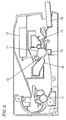
- Figure 1 shows a configuration of an optical scanner according to the present invention in a scanning plane.
- Figure 2 is a sectional view of the optical scanner taken along a plane parallel to a sub-scanning direction including a scanning center axis.
- the optical scanner of the present invention includes a semiconductor laser 1 , a collimator lens 2 , a cylindrical lens 3 having a refractive power only in the sub-scanning direction, a reflex mirror 4 , a polygon mirror 5 having a rotation center axis 6 , an axial-symmetric aspherical mirror 7 , and a correction lens 8 with a saddle toroidal incident surface and an aspherical cylindrical emergent surface.
- the reference numeral 9 denotes a photosensitive drum, and W (mm) denotes an effective scanning width.
- a light flux from the semiconductor laser 1 is made parallel by the collimator lens 2 , and then converged in the sub-scanning direction by the cylindrical lens 3 .
- the light is then reflexed by the reflex mirror 4 to be converged on a reflection surface of the polygon mirror 5 as a linear image.
- the light is scanned as the polygon mirror 5 rotates around the rotation center axis 6 , and is converged on the photosensitive drum 9 via the aspherical mirror 7 and the correction lens 8 to form an image on the photosensitive drum 9 .
- the curvature of field in the scanning direction and the f ⁇ characteristics are effectively corrected mainly by the aspherical mirror 7 and the emergent surface of the correction lens 8 , while the curvature of field in the sub-scanning direction is effectively corrected by the incident surface of the correction lens 8 .
- An example of an incident surface of a correction lens 8 not forming part of the invention as claimed is a saddle toroidal surface which is expressed by formula (8) below when z (mm) is the sag at a position of x (mm) in the sub-scanning direction and y (mm) in the scanning direction in a coordinate having the vertex of the surface as the origin from the tangent plane of the vertex where the direction toward the photosensitive drum 9 is positive: wherein R 1H (mm) is the radius of curvature in the scanning direction, R 1V (mm) is the radius of curvature in the sub-scanning direction, K 1 is the conical constant relating to the scanning direction, and D 1 , E 1 , F 1 , and G 1 are the higher-order constants relating to the scanning direction.
- the emergent surface of the correction lens 8 is an aspherical cylindrical surface or a barrel toroidal surface which is expressed by formula (9) below when z (mm) is the sag at a position of x (mm) in the sub-scanning direction and y (mm) in the scanning direction in a coordinate having the vertex of the surface as the origin where the direction toward the photosensitive drum 9 is positive: wherein R 2H (mm) is the radius of curvature in the scanning direction, R 2V (mm) is the radius of curvature in the sub-scanning direction, K 2 is the conical constant relating to the scanning direction, and D 2 , E 2 , F 2 , and G 2 are the higher-order constants relating to the scanning direction.
- f m (mm) denotes the focal length of a second image formation optical system in the scanning direction
- n denotes the refractive index of the lens material for the correction lens 5 at the wavelength of 780 nm.
- z e +y is equivalent to z ⁇ 10 +y .
- 1.2e+02 is equivalent to 1.2 X 10 2 , that is 120.
- a light flux from a light source is incident to a reflection surface of an optical deflector via a first image formation optical system.
- the light flux is scanned by the rotating optical deflector, and converged on a surface to be scanned via a second image formation optical system to form an image on the surface to be scanned.
- the curvature of field and the f ⁇ characteristics are effectively corrected by the second image formation optical system composed of a curved mirror and a correction lens where the refractive power in the sub-scanning direction at the center thereof in the scanning direction is different from that at the periphery thereof.
- the incident surface of the correction lens is a saddle toroidal surface where a circular arc or a curve having fourth or higher order development terms which is present in a plane parallel to the scanning direction and including the optical axis is rotated around a rotational symmetric axis which is parallel to the scanning direction and is present in the plane including the optical axis.
- the emergent surface of the correction lens is a cylindrical surface having a refracting force only in the scanning direction; an aspherical cylindrical surface having a refracting force only in the scanning direction where the section in the scanning direction has fourth or higher order development terms; or a barrel toroidal surface where a curve having fourth or higher order development terms, which is parallel to the scanning direction, and present in a place including the optical axis is rotated around a rotational symmetric axis which is parallel to the scanning direction and present in the place including the optical axis.
- the f ⁇ characteristics can be effectively corrected.
- conditional formula (1) below is satisfied: 0.159( L f m +C 1 ) 2 +C 2 -0.267 ⁇ Zm f m ⁇ 0.159( L f m +C 1 ) 2 +C 2 -0.257
- C 1 0.388( W f m ) 2 -0.416 W f m -0.217
- C 2 0.153( W f m ) 2 -0.404 W f m
- the curvature of field and the f ⁇ characteristics are effectively corrected.
- the curved mirror is an axial-symmetric aspherical surface, so as to realize the precision processing easily.
- conditional formula (2) when the displacement of the vertex of the curved mirror from the optical axis in the sub-scanning direction is x m (mm), conditional formula (2) below is satisfied. If the value exceeds the upper limit of formula (2), the corrections of the curvature of field and the f ⁇ characteristics are difficult. If the value is less than the lower limit of formula (2), the center of the curved mirror where an error in the shape tends to occur at the processing of the mirror is within an effective practical range. This requires a fabrication process with higher precision, resulting in an increase in cost. 0.5 ⁇ x m ⁇ 5.0
- conditional formula (3) when the distance between the reflection point of the curved mirror and the incident surface of the correction lens is M (mm), conditional formula (3) below is satisfied. If the value exceeds the upper limit of formula (3), the variation in the thickness of the correction lens becomes large, making it difficult to process the correction lens. If the value is less than the lower limit thereof, the corrections of the curvature of field and the f ⁇ characteristics become difficult. 0.43(1- L f m ) ⁇ M f m ⁇ 0.75
- conditional formula (4) when the angle formed by the plane vertical to the reflection surface of the optical deflector and parallel to the scanning direction and the optical axis of the first image formation optical system is ⁇ P (deg.), and the displacement of the center of the incident surface of the correction lens from the optical axis in the sub-scanning direction is x L (mm), conditional formula (4) below is satisfied. If formula (4) is not satisfied, an aberration is generated in a light ray in an oblique direction across the pupil of the lens. 0.11( L f m -0.043 M f m +0.007 ⁇ 5•X L f m • ⁇ ⁇ ⁇ 0.11 L f m -0.043 M f m +0.0155
- conditional formula (5) below is satisfied. If formula (5) is not satisfied, the scanning lines on the surface to be scanned curve in the sub-scanning direction. 0.31 L f m -0.162 - ( M f m -0.738) 2 0.42( L f m ) 2 +0.00272 +1.5 ⁇ m ⁇ 5 ⁇ ⁇ ⁇ 0.31 L f m -0.162 - ( M f m -0.738) 2 0.42( L f m ) 2 +0.00272 +4.5
- FIG 3 shows the configuration of an image formation apparatus using the scanning optics of the present invention.
- the image formation apparatus includes a photosensitive drum 11 covered with a photosensitive body whose electric charges change when irradiated with light, a primary electrifier 12 for attaching electrostatic ions to the surface of the photosensitive body to electrify the photosensitive body, an optical scanner 13 of the present invention for writing printing information on the photosensitive drum 11, a developer 14 for attaching electrified toner to printing portions, a transfer electrifier 15 for transferring the attached toner to a sheet, a cleaner 16 for removing remaining toner, a fixing device 17 for fixing the transferred toner to the sheet, and a feed cassette 18 .
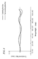
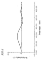
- Figures 4 and 5 show the remaining curvature of field and the f ⁇ characteristics, respectively, obtained in the scanning optics according to the present invention.
Description
- The present invention relates to an optical scanner used for laser beam printers, laser facsimiles, digital copying machines, and the like.
- Many types of optical scanner used for laser beam printers and the like include a semiconductor laser as a light source, a first image formation optical system for converging a light flux from the light source onto an optical deflector linearly for correcting a tilt of a deflection surface of the light deflector, a polygon mirror as the optical deflector, and a second image formation optical system for forming uniform spots on a surface to be scanned at a constant velocity.
- The second image formation optical system is conventionally composed of a plurality of large-size glass lenses called a f lens. The f lens is disadvantageous in that it is expensive and the size reduction thereof is difficult. In order to overcome these problems and realize a small-size, inexpensive optical scanner; there have been proposed, for example, optical scanners which use a cylindrical mirror and a cylindrical lens (Japanese Laid-Open Patent Publication No. 1-300218), a spherical mirror and a cylindrical lens (Japanese Laid-Open Patent Publication No. 1-300217), and an aspherical mirror and a long cylinder optical element (e.g., a long toric lens) (USP 5,408,095 or USP 5,173,798) for the second image formation optical system.
- However, in any of the above proposed optical systems, the correction of the curvature of field and the f correction are not sufficient and thus it is difficult to obtain an optical scanner with high resolution.
- The optical scanner of this invention includes a light source, an optical deflector for scanning a light flux from the light source, a first image formation optical system disposed between the light source and the optical deflector, and a second image formation optical system disposed between the optical deflector and a surface to be scanned, wherein the second image formation optical system includes a curved mirror for reflecting a light flux from the optical deflector and a correction lens for converging the light flux from the curved mirror on the surface to be scanned, a refractive power in a sub-scanning direction at a center of the correction lens in a scanning direction being different from a refractive power in a sub-scanning direction at a periphery of the correction lens, wherein, when a distance between a reflection point of the optical deflector and a reflection point of the curved mirror is L (mm), a distance between the reflection point of the curved mirror and an incident surface of the correction lens is M (mm), and the focal length of the second image formation optical system in the scanning direction is fm (mm), conditional formula (3) below is satisfied:
- In one embodiment of the invention, an emergent surface of the correction lens is a cylindrical surface having a refractive power only in the scanning direction.
- In another embodiment of the invention, an emergent surface of the correction lens is a aspherical cylindrical surface which has a refractive power only in the scanning direction and the section of the surface in the scanning direction has fourth or higher order development terms.
- In still another embodiment of the invention, when a focal length of the second image formation optical system in the scanning direction is fm (mm), an effective scanning width of the surface to be scanned is W (mm), a distance between a deflection point of the optical deflector and a reflection point of the curved mirror is L (mm), and a distance between an effective outermost position of the curved mirror in the scanning direction and a tangent plane of a vertex of the mirror surface is zm (mm), conditional formula (1) below is satisfied:
- In still another embodiment of'the invention, the curved mirror has an axial-symmetric aspherical surface.
- In still another embodiment of the invention, when a displacement of a vertex of the curved mirror from an optical axis is xm (mm), conditional formula (2) below is satisfied:
- In still another embodiment of the invention, an angle formed by a plane vertical to a reflection surface of the optical deflector and parallel to the scanning direction and an optical axis of the first image formation optical system is βP (deg.), a distance between a reflection point of the optical deflector and a reflection point of the curved mirror is L (mm), a distance between the reflection point of the curved mirror and the incident surface of the correction lens is M (mm), a focal length of the second image formation optical system in the scanning direction is fm (mm), and a displacement of a center of the incident surface of the correction lens from the optical axis in the sub-scanning direction is xL (mm), conditional formula (4) below is satisfied:
- In still another embodiment of the invention, an angle formed by a plane vertical to a reflection surface of the optical deflector and parallel to the scanning direction and an optical axis of the first image formation optical system is βP (deg.), a distance between a reflection point of the optical deflector and a reflection point of the curved mirror is L (mm), a distance between the reflection point of the curved mirror and an incident surface of the correction lens is M (mm), a focal length of the second image formation optical system in the scanning direction is fm (mm), and an angle formed by a normal to a vertex of the curved mirror and the optical axis is βm (deg.), conditional formula (5) below is satisfied:
- In still another embodiment of the invention, a focal length of the second image formation optical system in the scanning direction is fm (mm), and an effective scanning width of the surface to be scanned is W (mm), conditional formula (6) below is satisfied:
- In another aspect of the invention, the optical scanner comprises a light source, an optical deflector for scanning a light flux from the light source, a first image formation optical system disposed between the light source and the optical deflector, and a second image formation optical system disposed between the optical deflector and a surface to be scanned, wherein the second image formation optical system includes a curved mirror for reflecting a light flux from the optical deflector and a correction lens for correcting the light flux from the curved mirror on the surface to be scanned, a refractive power in a sub-scanning direction at a center of the correction lens in a scanning direction being different from a refractive power in a subscanning direction at a periphery of the correction lens,
characterized in that the incident surface of the correction lens is a saddle toroidal surface having a profile defined by a curve having fourth or higher order development terms which is present in the plane comprising the scanning direction and the optical axis of the optical system, and is rotated around a rotational symmetric axis which is parallel to the scanning direction and is present in the plane including the optical axis. - In one embodiment of the invention, an emergent surface of the correction lens is a cylindrical surface having a refractive power only in the scanning direction.
- In another embodiment of the invention, an emergent surface of the correction lens is a aspherical cylindrical surface which has a refractive power only in the scanning direction and the section of the surface in the scanning direction has fourth or higher order development terms.
- In still another embodiment of the invention, when a focal length of the second image formation optical system in the scanning direction is fm (mm), an effective scanning width of the surface to be scanned is W (mm), a distance between a deflection point of the optical deflector and a reflection point of the curved mirror is L (mm), and a distance between an effective outermost position of the curved mirror in the scanning direction and a tangent plane of a vertex of the mirror surface is zm (mm), conditional formula (1) below is satisfied:
- In still another embodiment of the invention, when a displacement of a vertex of the curved mirror from an optical axis is xm (mm), conditional formula (2) below is satisfied:
- In still another embodiment of the invention, when a distance between a reflection point of the optical deflector and a reflection point of the curved mirror is L (mm), a distance between the reflection point of the curved mirror and an incident surface of the correction lens is M (mm), and the focal length of the second image formation optical system in the scanning direction is fm (mm), conditional formula (3) below is satisfied:
- In still another embodiment of the invention, an angle formed by a plane vertical to a reflection surface of the optical deflector and parallel to the scanning direction and an optical axis of the first image formation optical system is βP (deg.), a distance between a reflection point of the optical deflector and a reflection point of the curved mirror is L (mm), a distance between the reflection point of the curved mirror and the incident surface of the correction lens is M (mm), a focal length of the second image formation optical system in the scanning direction is fm (mm), and a displacement of a center of the incident surface of the correction lens from the optical axis in the sub-scanning direction is xL (mm), conditional formula (4) below is satisfied:
- In still another embodiment of the invention, an angle formed by a plane vertical to a reflection surface of the optical deflector and parallel to the scanning direction and an optical axis of the first image formation optical system is βP (deg.), a distance between a reflection point of the optical deflector and a reflection point of the curved mirror is L (mm), a distance between the reflection point of the curved mirror and an incident surface of the correction lens is M (mm), a focal length of the second image formation optical system in the scanning direction is fm (mm), and an angle formed by a normal to a vertex of the curved mirror and the optical axis is βm (deg.), conditional formula (5) below is satisfied:
- In still another embodiment of the invention, a focal length of the second image formation optical system in the scanning direction is fm (mm), and an effective scanning width of the surface to be scanned is W (mm), conditional formula (6) below is satisfied:
- Alternatively, an image formation apparatus using the optical scanner is provided.
- Thus, the invention described herein makes possible the advantages of (1) providing an optical scanner where high resolution can be realized with a reduction in size and cost and (2) providing a small-size and inexpensive image formation apparatus with high resolution by use of the above optical scanner.
- These and other advantages of the present invention will become apparent to those skilled in the art upon reading and understanding the following detailed description with reference to the accompanying figures.
-
- Figure 1 shows a configuration of an optical scanner according to the present invention in a scanning plane.
- Figure 2 is a sectional view of the optical scanner according to the present invention taken along a sub-scanning direction.
- Figure 3 shows a configuration of an image formation apparatus according to the present invention.
- Figure 4 shows the curvature of field of a scanning optics according to the present invention.
- Figure 5 shows the f characteristics of a scanning optics according to the present invention.
-
- The present invention will be described by way of examples with reference to the accompanying drawings.
- Figure 1 shows a configuration of an optical scanner according to the present invention in a scanning plane. Figure 2 is a sectional view of the optical scanner taken along a plane parallel to a sub-scanning direction including a scanning center axis. Referring to Figure 1, the optical scanner of the present invention includes a semiconductor laser 1, a collimator lens 2, a cylindrical lens 3 having a refractive power only in the sub-scanning direction, a reflex mirror 4, a polygon mirror 5 having a rotation center axis 6, an axial-symmetric aspherical mirror 7, and a correction lens 8 with a saddle toroidal incident surface and an aspherical cylindrical emergent surface. The reference numeral 9 denotes a photosensitive drum, and W (mm) denotes an effective scanning width.
- The operation of the scanning optics with the above configuration will be described with reference to Figures 1 and 2.
- A light flux from the semiconductor laser 1 is made parallel by the collimator lens 2, and then converged in the sub-scanning direction by the cylindrical lens 3. The light is then reflexed by the reflex mirror 4 to be converged on a reflection surface of the polygon mirror 5 as a linear image. The light is scanned as the polygon mirror 5 rotates around the rotation center axis 6, and is converged on the photosensitive drum 9 via the aspherical mirror 7 and the correction lens 8 to form an image on the photosensitive drum 9. During the above process, the curvature of field in the scanning direction and the f characteristics are effectively corrected mainly by the aspherical mirror 7 and the emergent surface of the correction lens 8, while the curvature of field in the sub-scanning direction is effectively corrected by the incident surface of the correction lens 8.
- The shape of the axial-symmetric aspherical mirror 7 is expressed by formula (7) below when z (mm) is the sag at a coordinate p (mm) with regard to the symmetric axis from the tangent plane of the vortex of the surface, i.e., the distance between the coordinate p and the tangent plane of the vertex of the plane, where the direction toward the photosensitive drum 9 is positive:
- An example of an incident surface of a correction lens 8 not forming part of the invention as claimed is a saddle toroidal surface which is expressed by formula (8) below when z (mm) is the sag at a position of x (mm) in the sub-scanning direction and y (mm) in the scanning direction in a coordinate having the vertex of the surface as the origin from the tangent plane of the vertex where the direction toward the photosensitive drum 9 is positive:wherein R1H (mm) is the radius of curvature in the scanning direction, R1V (mm) is the radius of curvature in the sub-scanning direction, K1 is the conical constant relating to the scanning direction, and D1, E1, F1, and G1 are the higher-order constants relating to the scanning direction.

- The emergent surface of the correction lens 8 is an aspherical cylindrical surface or a barrel toroidal surface which is expressed by formula (9) below when z (mm) is the sag at a position of x (mm) in the sub-scanning direction and y (mm) in the scanning direction in a coordinate having the vertex of the surface as the origin where the direction toward the photosensitive drum 9 is positive:wherein R2H (mm) is the radius of curvature in the scanning direction, R2V (mm) is the radius of curvature in the sub-scanning direction, K2 is the conical constant relating to the scanning direction, and D2, E2, F2, and G2 are the higher-order constants relating to the scanning direction.

- The reference codes in Figure 2 denote the following:
- L (mm): distance between the deflection point of the polygon mirror 5 and the reflection point of the aspherical mirror 7;
- M (mm): distance between the reflection point of the aspherical mirror 7 and the incident surface of the correction lens 8;
- th (mm): center thickness of the correction lens 8;
- r (mm): distance between the reflection surface of the polygon mirror 5 and the rotation center axis 6 thereof;
- xm (mm): displacement of the vertex of the aspherical mirror 7 from the optical axis in the sub-scanning direction, i.e., distance between the normal to the vertex of the aspherical mirror 7 and the reflection point of the polygon mirror 5;
- xL (mm): displacement of the center of the incident surface of the correction lens 8 from the optical axis in the sub-scanning direction, i.e., distance between the incident point of the optical axis to the correction lens 8 and the normal to the vertex of the incident surface of the correction lens 8;
- βp (deg.): angle formed by the plane vertical to the reflection surface of the polygon mirror 5 and parallel to the scanning direction and the optical axis of the reflex mirror 4; and
- βm (deg.): angle formed by the normal to the vertex of the aspherical mirror 7 and the optical axis.
-
- Next, examples of the parameters of an optical scanner are shown in the following tables as Examples 1 to 22. In the tables, fm (mm) denotes the focal length of a second image formation optical system in the scanning direction, and n denotes the refractive index of the lens material for the correction lens 5 at the wavelength of 780 nm. In the following tables, the expression "z e +y" is equivalent to z × 10+y. For example, "1.2e+02" is equivalent to 1.2 X 10², that is 120.
-
W 220 L 36.0 M 62.5 r 17.32 Xm 1.0 XL 2.00 βp 4.2 βm 3.75 fm 135.471 Rm 246.2630 th 10 R1H -500.110 R2H 1004.954 Km -1.59656e+01 n 1.51922 R1V 19.769 R2V 133.475 Dm -1.63932e-07 K1 0.00000 K2 0.00000 Em 8.48113e-11 D1 3.63763e-08 D2 -3.85296e-07 Fm -2.46270e-14 E1 -5.89551e-12 E2 3.56933e-11 Gm 2.88553e-18 F1 -5.28400e-16 F2 -3.29169e-15 G1 9.29471e-21 G2 1.39801e-19 -
W 220 L 36.0 M 62.5 r 17.32 Xm 1.0 xL 2.60 β p 4.8 β m 3.75 fm 135.461 Rm 245.538 th 6 R1H -420.802 R2H 1520.693 Km -2.03787e+01 n 1.51922 R1V 22.492 R2V ∞ Dm -1.50852e-07 K1 0.00000 K2 0.00000 Em 9.86386e-11 D1 1.01764e-08 D2 -4.37046e-07 Fm -3.99974e-14 E1 2.01354e-13 E2 4.26431e-11 Gm 7.61824e-18 F1 8.58569e-16 F2 2.92046e-15 G1 -1.18174e-19 G2 3.09542e-20 -
W 220 L 36.0 M 45.0 r 17.32 xm 1.5 xL 3.25 β p 5.0 β m 1.0 fm 135.666 Rm 231.271 th 10 R1H -330.159 R2H 919.966 Km -3.32353e+01 n 1.51922 R1V 24.272 R2V ∞ Dm -9.14563e-08 K1 0.00000 K2 0.00000 Em 7.22560e-11 D1 3.71320e-08 D2 -6.46412e-07 Fm -2.76691e-14 E1 -2.70826e-12 E2 9.45474e-11 Gm 4.29321e-18 F1 -3.07221e-16 F2 -1.22253e-14 G1 9.62415e-20 G2 6.94307e-19 -
W 220 L 36.0 M 55.0 r 17.32 xm 1.5 xL 3.00 β p 5.0 β m 3.0 fm 135.506 Rm 239.737 th 10 R1H -370.703 R2H 1245.574 Km -2.72444e+01 n 1.51922 R1V 23.526 R2V ∞ Dm -1.05916e-07 K1 0.00000 K2 0.00000 Em 8.57296e-11 D1 4.43867e-08 D2 -4.75137e-07 Fm -3.76883e-14 E1 -5.56782e-12 E2 5.72248e-11 Gm 7.50089e-18 F1 5.29870e-16 F2 -6.55023e-15 G1 -1.45599e-20 G2 3.30934e-19 -
W 220 L 36.0 M 62.5 r 17.32 xm 1.5 XL 2.60 β p 5.0 β m 3.75 fm 135.400 Rm 244.281 th 10 R1H -413.180 R2H 1209.886 Km -1.94544e+01 n 1.51922 R1V 22.557 R2V ∞ Dm -1.46423e-07 K1 0.00000 K2 0.00000 Em 9.83633e-11 D1 3.05549e-08 D2 -4.04940e-07 Fm -4.08015e-14 E1 -3.20937e-12 E2 3.95771e-11 Gm 7.92061e-18 F1 7.11185e-16 F2 -3.31930e-15 G1 -6.99536e-20 G2 1.02164e-19 -
W 220 L 36.0 M 75.0 r 17.32 xm 1.5 xL 2.00 β p 5.0 β m 5.25 fm 135.055 Rm 248.615 th 10 R1H -491.670 R2H 813.007 Km -1.46706e+01 n 1.51922 R1V 20.277 R2V ∞ Dm -1.52865e-07 K1 0.00000 K2 0.00000 Em 1.02675e-10 D1 3.94670e-08 D2 -3.36010e-07 Fm -4.55279e-14 E1 -2.60797e-12 E2 3.08420e-11 Gm 9.22406e-18 F1 -2.114404-16 F2 -3.03034e-15 G1 3.06827e-20 G2 1.26506e-19 -
W 220 L 36.0 H 90.0 r 17.32 xm 1.5 xL 1.50 β p 5.0 β m 6.25 fm 134.835 Rm 251.998 th 10 R1H -709.362 R2H 392.109 Km -1.05614e+01 n 1.51922 R1V 16.417 R2V ∞ Dm -1.41582e-07 K1 0.00000 K2 0.00000 Em 7.54551e-11 D1 1.63683e-08 D2 -3.23877e-07 Fm -2.43957e-14 E1 6.38129e-12 E2 2.97499e-11 Gm 2.81184e-18 F1 -1.67552e-15 F2 -3.26806e-15 G1 1.00364e-19 G2 1.36524e-19 -
W 220 L 36.0 M 100.0 r 17.32 xm 1.5 xL 0.00 β p 5.0 β m 6.0 fm 134.942 Rm 255.010 th 10 R1H -1502.287 R2H 238.937 Km -7.80814e+00 n 1.51922 R1V 13.026 R2V ∞ Dm -1.36071e-07 K1 0.00000 K2 0.00000 Em 6.46895e-11 D1 -3.56089e-08 D2 -3.53823e-07 Fm -1.85439e-14 E1 1.48866e-11 E2 3.29342e-11 Gm 1.07796e-18 F1 -2.18320e-15 F2 -3.80356e-15 G1 9.55852e-20 G2 1.43061e-19 -
W 220 L 50.0 M 60.0 r 17.32 xm 1.5 xL 3.75 β p 5.0 β m 2.5 fm 135.735 Rm 251.692 th 10 R1H -530.316 R2H 3696.546 Km 9.64148e-01 n 1.51922 R1V 25.770 R2V ∞ Dm -1.23714e-07 K1 0.00000 K2 0.00000 Em 1.63463e-11 D1 2.28444e-08 D2 -2.17034e-07 Fm -1.64810e-15 E1 -2.43966e-12 E2 1.17745e-11 Gm 0.00000 F1 1.44160e-16 F2 -4.75011e-16 G1 0.00000 G2 0.00000 -
W 220 L 50.0 M 100.0 r 17.32 xm 1.5 xL 2.00 β p 5.0 β m 4.5 fm 135.478 Rm 260.082 th 10 R1H -1588.665 R2H 402.961 Km 7.00774e+00 n 1.51922 R1V 14.644 R2V ∞ Dm -1.24741e-07 K1 0.00000 K2 0.00000 Em 7.18887e-12 D1 5.64607e-09 D2 -1.72211e-07 Fm -1.56599e-15 E1 -1.59469e-12 E2 9.13411e-13 Gm 0.00000 F1 4.67380e-17 F2 -4.68695e-18 G1 0.00000 G2 0.00000 -
W 220 L 60.0 M 35.0 r 17.32 xm 1.5 xL 5.75 β p 5.0 β m 0.75 fm 135.833 Rm 244.537 th 10 R1H -606.287 R2H 1667.512 Km 8.51804e-01 n 1.51922 R1V 32.518 R2V ∞ Dm -1.01091e-07 K1 0.00000 K2 0.00000 Em 9.04368e-12 D1 -3.68083e-08 D2 -2.84790e-07 Fm -6.34970e-16 E1 9.34622e-12 E2 2.61246e-11 Gm 0.00000 F1 8.01597e-16 F2 -1.50801e-15 G1 0.00000 G2 0.00000 -
W 220 L 70.0 M 35.0 r 17.32 Xm 1.5 XL 7.00 β p 5.0 β m 1.5 fm 135.796 Rm 253.930 th 10 B1H -747.578 R2H 38572.78 Km 4.04873e+00 n 1.51922 R1V 35.811 R2V ∞ Dm -7.74599e-08 K1 0.00000 K2 0.00000 Em 1.94745e-12 D1 -3.80465e-08 D2 -1.62724e-07 Fm -3.03958e-16 E1 8.97492e-12 E2 1.55766e-11 Gm 0.00000 F1 -6.72123e-16 F2 -8.41019e-16 G1 0.00000 G2 0.00000 -
W 220 L 80.0 M 35.0 r 17.32 xm 1.5 xL 8.00 β p 5.0 β m 2.25 fm 135.731 Rm 263.487 th 10 R1H -894.161 R2H -1754.17 Km 3.30594e+00 n 1.51922 R1V 38.920 R2V ∞ Dm -4.33704e-08 K1 0.00000 K2 0.00000 Em 4.46328e-13 D1 -3.61652e-08 D2 -8.41032e-08 Fm -1.06606e-16 E1 -7.04205e-12 E2 9.86436e-12 Gm 0.00000 F1 -4.72947e-16 F2 -4.94179e-16 G1 0.00000 G2 0.00000 -
W 220 L 80.0 M 25.0 r 17.32 xm 1.5 xL 9.00 β p 5.0 β m 2.25 fm 135.708 Rm 262.705 th 10 R1H -856.991 R2H -1608.667 Km -3.15765e+00 n 1.51922 R1V 41.394 R2V ∞ Dm -4.60391e-08 K1 0.00000 K2 0.00000 Em 7.88534e-13 D1 -3.50227e-08 D2 -9.48573e-08 Fm -1.06984e-16 E1 5.92193e-12 E2 9.82103e-12 Gm 0.00000 F1 -4.14847e-16 F2 -4.57249e-16 G1 0.00000 G2 0.00000 -
W 220 L 80.0 M 75.0 r 17.32 xm 1.5 XL 6.00 β p 5.0 β m 3.0 fm 135.724 Rm 268.115 th 10 R1H -1257.495 R2H -2257.703 Km 2.38284e+00 n 1.51922 R1V 27.353 R2V ∞ Dm -2.99461e-08 K1 0.00000 K2 0.00000 Em 1.38238e-13 D1 -3.35062e-10 D2 -3.10692e-08 Fm -4.11335e-17 E1 1.66667e-13 E2 1.47339e-12 Gm 0.00000 F1 -7.07430e-18 F2 -1.80438e-17 G1 0.00000 G2 0.00000 -
W 220 L 80.0 M 75.0 r 17.32 xm 1.5 xL 3.00 β p 2.5 β m 1.5 fm 135.530 Rm 269.986 th 10 R1H -1358.679 R2H -2535.109 Km 2.14515e+00 n 1.51922 R1V 26.200 R2V ∞ Dm -2.79445e-08 K1 0.00000 K2 0.00000 Em 1.59213e-13 D1 -4.01994e-10 D2 -2.93461e-08 Fm -3.33182e-17 E1 3.17189e-13 E2 1.55062e-12 Gm 0.00000 F1 -1.55018e-17 F2 -2.28660e-17 G1 0.00000 G2 0.00000 -
W 220 L 36.0 M 62.5 r 17.32 xm 1.5 xL 2.60 β p 5.0 β m 3.75 fm 131.6983 Rm 242.079 th 10 R1H -420.617 R2H 3140.212 Km -1.76081e+01 n 1.51922 R1V 22.098 R2V ∞ Dm -1.43480e-07 K1 0.00000 K2 0.00000 Em 9.50088e-11 D1 3.25198e-08 D2 -3.85403e-07 Fm -4.03494e-14 E1 -4.67309e-12 E2 3.56563e-11 Gm 7.92061e-18 F1 8.83310e-16 F2 -3.09489e-15 G1 -6.99536e-20 G2 1.02164e-19 -
W 220 L 60.0 M 35.0 r 17.32 xm 1.5 xL 5.75 β p 5.0 β m 0.75 fm 132.127 Rm 240.626 th 10 R1H -573.848 R2H 3365.851 Km 1.17583e+00 n 1.51922 R1V 32.014 R2V ∞ Dm -9.82525e-08 K1 0.00000 K2 0.00000 Em 8.01295e-12 D1 1.24037e-09 D2 -2.31664e-07 Fm -5.65937e-16 E1 -7.60029e-13 E2 1.55087e-11 Gm 0.00000 F1 9.79549e-17 F2 -6.77801e-16 G1 0.00000 G2 0.00000 -
W 220 L 80.0 M 75.0 r 17.32 xm 1.5 xL 6.00 β p 5.0 β m 3.0 fm 131.996 Rm 263.704 th 10 R1H -1302.421 R2H -1213.420 Km 2.25434e+00 n 1.51922 R1V 26.466 R2V ∞ Dm -2.86539e-08 K1 0.00000 K2 0.00000 Em 6.15671e-14 D1 -7.59746e-09 D2 -3.33379e-08 Fm -3.66942e-17 E1 1.36110e-12 E2 2.61977e-12 Gm 0.00000 F1 -6.94622e-17 F2 -7.43665e-17 G1 0.00000 G2 0.00000 -
W 220 L 36.0 M 62.5 r 17.32 Xm 1.5 XL 2.60 β p 5.0 β m 3.75 fm 120.167 Rm 232.407 th 10 R1H -450.127 R2H -851.987 Km -9.34985e+00 n 1.51922 R1V 20.441 R2V ∞ Dm -1.80751e-07 K1 0.00000 K2 0.00000 Em 1.03536e-10 D1 3.13383e-08 D2 -3.63835e-07 Fm -4.37516e-14 E1 -6.82411e-12 E2 3.08486e-11 Gm 7.92061e-18 F1 1.15113e-15 F2 -2.97136e-15 G1 -6.99536e-20 G2 1.02164e-19. -
W 220 L 60.0 M 35.0 r 17.32 xm 1.5 XL 5.75 β p 5.0 β m 0.75 fm 120.639 Rm 229.793 th 10 R1H -581.002 R2H -1609.465 Km 2.25008e+00 n 1.51922 R1V 30.395 R2V ∞ Dm -8.94697e-08 K1 0.00000 K2 0.00000 Em 3.86453e-12 D1 -7.06742e-09 D2 -1.75970e-07 Fm -2.88035e-16 E1 2.47273e-12 E2 1.12020e-11 Gm 0.00000 F1 -2.00818e-16 F2 -4.42406e-16 G1 0.00000 G2 0.00000 -
W 220 L 80.0 M 75.0 r 17.32 xm 1.5 xL 6.00 β p 5.0 β m 3.0 fm 120.491 Rm 248.140 th 10 R1H -1316.457 R2H -450.985 Km 1.74984e+00 n 1.51922 R1V 23.482 R2V ∞ Dm -2.58401e-08 K1 0.00000 K2 0.00000 Em 6.60495e-14 D1 -1.86170e-08 D2 -2.95194e-08 Fm -3.13230e-17 E1 2.86204e-12 E2 4.58838e-12 Gm 0.00000 F1 -1.31398e-16 F2 -1.41288e-16 G1 0.00000 G2 0.00000 - Hereinbelow, the conditions satisfied by examplary scanning optics will be described, together with the effects obtained when the conditions are satisfied.
- In examples not forming part of the invention as claimed, a light flux from a light source is incident to a reflection surface of an optical deflector via a first image formation optical system. The light flux is scanned by the rotating optical deflector, and converged on a surface to be scanned via a second image formation optical system to form an image on the surface to be scanned. The curvature of field and the f characteristics are effectively corrected by the second image formation optical system composed of a curved mirror and a correction lens where the refractive power in the sub-scanning direction at the center thereof in the scanning direction is different from that at the periphery thereof. Thus, a small-size, inexpensive optical scanner with high resolution can be realized.
- In examples not forming part of the invention as claimed, the incident surface of the correction lens is a saddle toroidal surface where a circular arc or a curve having fourth or higher order development terms which is present in a plane parallel to the scanning direction and including the optical axis is rotated around a rotational symmetric axis which is parallel to the scanning direction and is present in the plane including the optical axis. Thus, the refractive power in the sub-scanning direction at the center of the correction lens in the scanning direction can be made different from that at the periphery thereof at low cost.
- In examples not forming part of the invention as claimed, the emergent surface of the correction lens is a cylindrical surface having a refracting force only in the scanning direction; an aspherical cylindrical surface having a refracting force only in the scanning direction where the section in the scanning direction has fourth or higher order development terms; or a barrel toroidal surface where a curve having fourth or higher order development terms, which is parallel to the scanning direction, and present in a place including the optical axis is rotated around a rotational symmetric axis which is parallel to the scanning direction and present in the place including the optical axis. Thus, the f characteristics can be effectively corrected.
- In examples not forming part of the invention as claimed, when the focal length of the second image formation optical system in the scanning direction is fm (mm), the effective scanning width of the surface to be scanned is W (mm), the distance between the deflection point of the optical deflector and the reflection point of the curved mirror is L (mm), and the distance between the effective outermost position of the curved mirror in the scanning direction and the tangent plane of the vertex of the mirror surface is zm (mm), conditional formula (1) below is satisfied:
- In examples not forming part of the invention as claimed, the curved mirror is an axial-symmetric aspherical surface, so as to realize the precision processing easily.
- In examples not forming part of the invention as claimed, when the displacement of the vertex of the curved mirror from the optical axis in the sub-scanning direction is xm (mm), conditional formula (2) below is satisfied. If the value exceeds the upper limit of formula (2), the corrections of the curvature of field and the f characteristics are difficult. If the value is less than the lower limit of formula (2), the center of the curved mirror where an error in the shape tends to occur at the processing of the mirror is within an effective practical range. This requires a fabrication process with higher precision, resulting in an increase in cost.
- In examples not forming part of the invention as claimed, when the distance between the reflection point of the curved mirror and the incident surface of the correction lens is M (mm), conditional formula (3) below is satisfied. If the value exceeds the upper limit of formula (3), the variation in the thickness of the correction lens becomes large, making it difficult to process the correction lens. If the value is less than the lower limit thereof, the corrections of the curvature of field and the f characteristics become difficult.
- In examples not forming part of the invention as claimed, when the angle formed by the plane vertical to the reflection surface of the optical deflector and parallel to the scanning direction and the optical axis of the first image formation optical system is βP (deg.), and the displacement of the center of the incident surface of the correction lens from the optical axis in the sub-scanning direction is xL (mm), conditional formula (4) below is satisfied. If formula (4) is not satisfied, an aberration is generated in a light ray in an oblique direction across the pupil of the lens.
- In examples not forming part of the invention as claimed,when the angle formed by the normal to the vertex of the curved mirror and the optical axis is βm (deg.), conditional formula (5) below is satisfied. If formula (5) is not satisfied, the scanning lines on the surface to be scanned curve in the sub-scanning direction.
- In examples not forming part of the invention as claimed, if the value exceeds the upper limit of conditional formula (6) below, the corrections of the curvature of field and the f characteristics become difficult. If the value is less than the lower limit thereof, it is difficult to reduce the size of the scanning optics.
- Figure 3 shows the configuration of an image formation apparatus using the scanning optics of the present invention. Referring to Figure 3, the image formation apparatus includes a photosensitive drum 11 covered with a photosensitive body whose electric charges change when irradiated with light, a primary electrifier 12 for attaching electrostatic ions to the surface of the photosensitive body to electrify the photosensitive body, an optical scanner 13 of the present invention for writing printing information on the photosensitive drum 11, a developer 14 for attaching electrified toner to printing portions, a transfer electrifier 15 for transferring the attached toner to a sheet, a cleaner 16 for removing remaining toner, a fixing device 17 for fixing the transferred toner to the sheet, and a feed cassette 18.
- Figures 4 and 5 show the remaining curvature of field and the f characteristics, respectively, obtained in the scanning optics according to the present invention.
- As described above, a small-size, inexpensive image formation apparatus can be realized by using the scanning optics of the present invention.
Claims (19)
- An optical scanner comprising a light source (1), an optical deflector (5) for scanning a light flux from the light source, a first image formation optical system (2, 3, 4) disposed between the light source and the optical deflector, and a second image formation optical system (7,8) disposed between the optical deflector and a surface to be scanned (9), wherein the second image formation optical system includes a curved mirror (7) for reflecting a light flux from the optical deflector (5) and a correction lens (8) for converging the light flux from the curved mirror on the surface to be scanned, the refractive power in the sub-scanning direction (x) at the centre of the correction lens (8) in the scanning direction (y) being different from the refractive power in the sub-scanning direction at a periphery of the correction lens, wherein, when a distance between a reflection point of the optical deflector and a reflection point of the curved mirror is L (mm), a distance between the reflection point of the curved mirror and an incident surface of the correction lens is M (mm), and the focal length of the second image formation optical system in the scanning direction is fm (mm), conditional formula (3) below is satisfied:
- An optical scanner according to claim 1, wherein an emergent surface of the correction lens (8) is a cylindrical surface having a refractive power only in the scanning direction.
- An optical scanner according to claim 1, wherein an emergent surface of the correction lens (8) is a aspherical cylindrical surface which has a refractive power only in the scanning direction and the section of the surface in the scanning direction has fourth or higher order development terms.
- An optical scanner according to claim 1, wherein, when a focal length of the second image formation optical system (7, 8) in the scanning direction is fm (mm), an effective scanning width of the surface to be scanned is W (mm), a distance between a deflection point of the optical deflector (5) and a reflection point of the curved mirror (7) is L (mm), and a distance between an effective outermost position of the curved mirror (7) in the scanning direction and a tangent plane of a vertex of the mirror surface is zm (mm), conditional formula (1) below is satisfied:
- An optical scanner according to claim 1, wherein the curved mirror (7) has an axial-symmetric aspherical surface.
- An optical scanner according to claim 1, wherein, when a displacement of a vertex of the curved mirror (7) from an optical axis is xm(mm), conditional formula (2) below is satisfied:
- An optical scanner according to claim 1, wherein an angle formed by a plane vertical to a reflection surface of the optical deflector and parallel to the scanning direction and an optical axis of the first image formation optical system is βP (deg.), a distance between a reflection point of the optical deflector and a reflection point of the curved mirror is L (mm), a distance between the reflection point of the curved mirror and the incident surface of the correction lens is M (mm), a focal length of the second image formation optical system in the scanning direction is fm (mm), and a displacement of a center of the incident surface of the correction lens from the optical axis in the sub-scanning direction is xL (mm), conditional formula (4) below is satisfied:
- An optical scanner according to claim 1, wherein an angle formed by a plane vertical to a reflection surface of the optical deflector and parallel to the scanning direction and an optical axis of the first image formation optical system is βP (deg.), a distance between a reflection point of the optical deflector and a reflection point of the curved mirror is L (mm), a distance between the reflection point of the curved mirror and an incident surface of the correction lens is M (mm), a focal length of the second image formation optical system in the scanning direction is fm (mm), and an angle formed by a normal to a vertex of the curved mirror and the optical axis is βm (deg.), conditional formula (5) below is satisfied:
- An optical scanner according to claim 1, wherein a focal length of the second image formation optical system in the scanning direction is fm (mm), and an effective scanning width of the surface to be scanned is W (mm), conditional formula (6) below is satisfied:
- An optical scanner comprising a light source (1), an optical deflector (5) for scanning a light flux from the light source, a first image formation optical system (2, 3, 4) disposed between the light source (1) and the optical deflector, and a second image formation optical system (7, 8) disposed between the optical deflector and a surface to be scanned (9), wherein the second image formation optical system includes a curved mirror (7) for reflecting a light flux from the optical deflector (5) and a correction lens (8) for correcting the light flux from the curved mirror on the surface to be scanned, the refractive power in the sub-scanning direction (x) at the center of the correction lens in the scanning direction (y) being different from the refractive power in the sub-scanning direction at the periphery of the correction lens, characterized in that the incident surface of the correction lens (8) is a saddle toroidal surface having a profile defined by a curve having fourth or higher order development terms which is present in the plane comprising the scanning direction and the optical axis of the optical system, and is rotated around a rotational symmetric axis which is parallel to the scanning direction and is present in the plane including the optical axis.
- An optical scanner according to claim 10, wherein an emergent surface of the correction lens is a cylindrical surface having a refractive power only in the scanning direction.
- An optical scanner according to claim 11, wherein an emergent surface of the correction lens is a aspherical cylindrical surface which has a refractive power only in the scanning direction and the section of the surface in the scanning direction has fourth or higher order development terms.
- An optical scanner according to claim 12, wherein, when a focal length of the second image formation optical system in the scanning direction is fm (mm), an effective scanning width of the surface to be scanned is W (mm), a distance between a deflection point of the optical deflector and a reflection point of the curved mirror is L (mm), and a distance between an effective outermost position of the curved mirror in the scanning direction and a tangent plane of a vertex of the mirror surface is zm (mm), conditional formula (1) below is satisfied:
- An optical scanner according to claim 13, wherein, when a displacement of a vertex of the curved mirror from an optical axis is xm (mm), conditional formula (2) below is satisfied:
- An optical scanner according to claim 14, wherein, when a distance between a reflection point of the optical deflector and a reflection point of the curved mirror is L (mm), a distance between the reflection point of the curved mirror and an incident surface of the correction lens is M (mm), and the focal length of the second image formation optical system in the scanning direction is fm (mm), conditional formula (3) below is satisfied:
- An optical scanner according to claim 15, wherein an angle formed by a plane vertical to a reflection surface of the optical deflector and parallel to the scanning direction and an optical axis of the first image formation optical system is βP (deg.), a distance between a reflection point of the optical deflector and a reflection point of the curved mirror is L (mm), a distance between the reflection point of the curved mirror and the incident surface of the correction lens is M (mm), a focal length of the second image formation optical system in the scanning direction is fm (mm), and a displacement of a center of the incident surface of the correction lens from the optical axis in the sub-scanning direction is xL (mm), conditional formula (4) below is satisfied:
- An optical scanner according to claim 16, wherein an angle formed by a plane vertical to a reflection surface of the optical deflector and parallel to the scanning direction and an optical axis of the first image formation optical system is βP (deg.), a distance between a reflection point of the optical deflector and a reflection point of the curved mirror is L (mm), a distance between the reflection point of the curved mirror and an incident surface of the correction lens is M (mm), a focal length of the second image formation optical system in the scanning direction is fm (mm), and an angle formed by a normal to a vertex of the curved mirror and the optical axis is βm (deg.), conditional formula (5) below is satisfied:
- An optical scanner according to claim 17, wherein a focal length of the second image formation optical system in the scanning direction is fm (mm), and an effective scanning width of the surface to be scanned is W (mm), conditional formula (6) below is satisfied:
- An image formation apparatus using the optical scanner according to claim 1.
Applications Claiming Priority (3)
| Application Number | Priority Date | Filing Date | Title |
|---|---|---|---|
| JP176847/94 | 1994-07-28 | ||
| JP17684794 | 1994-07-28 | ||
| JP17684794A JP3275548B2 (en) | 1994-07-28 | 1994-07-28 | Optical scanning device |
Publications (3)
| Publication Number | Publication Date |
|---|---|
| EP0694802A2 EP0694802A2 (en) | 1996-01-31 |
| EP0694802A3 EP0694802A3 (en) | 1998-01-14 |
| EP0694802B1 true EP0694802B1 (en) | 2001-12-12 |
Family
ID=16020876
Family Applications (1)
| Application Number | Title | Priority Date | Filing Date |
|---|---|---|---|
| EP95111758A Expired - Lifetime EP0694802B1 (en) | 1994-07-28 | 1995-07-26 | Optical scanner |
Country Status (4)
| Country | Link |
|---|---|
| US (1) | US5657147A (en) |
| EP (1) | EP0694802B1 (en) |
| JP (1) | JP3275548B2 (en) |
| DE (1) | DE69524492T2 (en) |
Families Citing this family (6)
| Publication number | Priority date | Publication date | Assignee | Title |
|---|---|---|---|---|
| US6400442B1 (en) | 1996-08-28 | 2002-06-04 | Polaroid Corporation | Optical system for use in a photographic printer |
| WO1999003012A1 (en) * | 1997-07-08 | 1999-01-21 | Etec Systems, Inc. | Anamorphic scan lens for laser scanner |
| IL133243A0 (en) | 1999-03-30 | 2001-03-19 | Univ Ramot | A method and system for super resolution |
| JP2001318331A (en) * | 2000-05-09 | 2001-11-16 | Asahi Optical Co Ltd | Reflection type scanning optical system |
| US6344893B1 (en) | 2000-06-19 | 2002-02-05 | Ramot University Authority For Applied Research And Industrial Development Ltd. | Super-resolving imaging system |
| CN112114425B (en) * | 2020-09-14 | 2022-06-07 | 福建福光股份有限公司 | Scanning type medium wave infrared optical system |
Citations (1)
| Publication number | Priority date | Publication date | Assignee | Title |
|---|---|---|---|---|
| US5408095A (en) * | 1992-07-22 | 1995-04-18 | Ricoh Company, Ltd. | Optical scanner having an image forming mirror and means for reducing scanning line pitch irregularities |
Family Cites Families (11)
| Publication number | Priority date | Publication date | Assignee | Title |
|---|---|---|---|---|
| JPS58500262A (en) * | 1981-02-23 | 1983-02-17 | ジエネラル オプトロニクス コ−ポレイシヨン | Improved grating scanner with anamorphic correction of scan curvature |
| JPS62127819A (en) * | 1985-11-29 | 1987-06-10 | Konishiroku Photo Ind Co Ltd | Scanning optical system |
| JPH01300218A (en) * | 1988-05-27 | 1989-12-04 | Minolta Camera Co Ltd | Light beam scanning optical system |
| JP2615850B2 (en) * | 1988-05-27 | 1997-06-04 | ミノルタ株式会社 | Light beam scanning optical system |
| JPH0215231A (en) * | 1988-07-04 | 1990-01-18 | Sankyo Seiki Mfg Co Ltd | Scanning optical system |
| JPH0769521B2 (en) * | 1988-07-13 | 1995-07-31 | 株式会社日立製作所 | Optical scanning device and scanning lens |
| JP2598473B2 (en) * | 1988-08-01 | 1997-04-09 | 株式会社リコー | Scanning optical system |
| JP2682675B2 (en) * | 1988-11-07 | 1997-11-26 | 株式会社リコー | Scanning optical system |
| JP2964629B2 (en) * | 1990-11-22 | 1999-10-18 | ミノルタ株式会社 | Laser beam scanning optical device |
| US5426298A (en) * | 1992-03-17 | 1995-06-20 | Ricoh Company, Ltd. | Optical scanner |
| JP3266725B2 (en) * | 1993-12-29 | 2002-03-18 | 旭光学工業株式会社 | Scanning optical system |
-
1994
- 1994-07-28 JP JP17684794A patent/JP3275548B2/en not_active Expired - Fee Related
-
1995
- 1995-07-24 US US08/505,974 patent/US5657147A/en not_active Expired - Lifetime
- 1995-07-26 EP EP95111758A patent/EP0694802B1/en not_active Expired - Lifetime
- 1995-07-26 DE DE69524492T patent/DE69524492T2/en not_active Expired - Fee Related
Patent Citations (1)
| Publication number | Priority date | Publication date | Assignee | Title |
|---|---|---|---|---|
| US5408095A (en) * | 1992-07-22 | 1995-04-18 | Ricoh Company, Ltd. | Optical scanner having an image forming mirror and means for reducing scanning line pitch irregularities |
Also Published As
| Publication number | Publication date |
|---|---|
| EP0694802A3 (en) | 1998-01-14 |
| DE69524492D1 (en) | 2002-01-24 |
| JPH0843753A (en) | 1996-02-16 |
| JP3275548B2 (en) | 2002-04-15 |
| DE69524492T2 (en) | 2002-07-18 |
| EP0694802A2 (en) | 1996-01-31 |
| US5657147A (en) | 1997-08-12 |
Similar Documents
| Publication | Publication Date | Title |
|---|---|---|
| US6388792B1 (en) | Optical scanning device and image forming apparatus | |
| JP4717285B2 (en) | Scanning optical device and image forming apparatus using the same | |
| JP3330248B2 (en) | Optical scanning device, image forming device, and image reading device | |
| EP0853253B1 (en) | Optical scanning apparatus | |
| KR20010107742A (en) | Optical scanning apparatus and image forming apparatus using the same | |
| JP5116559B2 (en) | Optical scanning device and image forming apparatus using the same | |
| JP4684470B2 (en) | Optical scanning device and image forming apparatus using the same | |
| US8400699B2 (en) | Optical scanning device and image forming apparatus using the same | |
| US20030043442A1 (en) | Scanning optical apparatus and image forming apparatus using the same | |
| JP4659277B2 (en) | Optical scanning device and image forming apparatus using the same | |
| JP3420956B2 (en) | Optical scanning device, image reading device and image forming device using the same | |
| JPH07113950A (en) | Light beam scanning device and image forming lens | |
| JP3943820B2 (en) | Optical scanning device, multi-beam optical scanning device, and image forming apparatus | |
| EP0694802B1 (en) | Optical scanner | |
| US20040109212A1 (en) | Optical scanning apparatus and image forming apparatus using the same | |
| JPH07318832A (en) | Scanning optical system and image forming device using the same | |
| JP2008170487A (en) | Optical scanner and image forming apparatus using the same | |
| JP2001296491A (en) | Optical scanner and image forming device using the same | |
| JPH07174998A (en) | Scanning lens and optical scanner | |
| JP2956169B2 (en) | Scanning optical device | |
| JP2003156704A (en) | Optical scanner and image forming device using the same | |
| JP4817526B2 (en) | Optical scanning device and image forming apparatus using the same | |
| JP2773593B2 (en) | Light beam scanning optical system | |
| JP3390118B2 (en) | Optical scanning device, image reading device and image forming device using the same | |
| JP4584827B2 (en) | Scanning imaging lens, optical scanning device, and image forming apparatus |
Legal Events
| Date | Code | Title | Description |
|---|---|---|---|
| PUAI | Public reference made under article 153(3) epc to a published international application that has entered the european phase |
Free format text: ORIGINAL CODE: 0009012 |
|
| 17P | Request for examination filed |
Effective date: 19950726 |
|
| AK | Designated contracting states |
Kind code of ref document: A2 Designated state(s): DE FR GB IT NL |
|
| PUAL | Search report despatched |
Free format text: ORIGINAL CODE: 0009013 |
|
| AK | Designated contracting states |
Kind code of ref document: A3 Designated state(s): DE FR GB IT NL |
|
| 17Q | First examination report despatched |
Effective date: 19980828 |
|
| GRAG | Despatch of communication of intention to grant |
Free format text: ORIGINAL CODE: EPIDOS AGRA |
|
| GRAG | Despatch of communication of intention to grant |
Free format text: ORIGINAL CODE: EPIDOS AGRA |
|
| GRAH | Despatch of communication of intention to grant a patent |
Free format text: ORIGINAL CODE: EPIDOS IGRA |
|
| GRAH | Despatch of communication of intention to grant a patent |
Free format text: ORIGINAL CODE: EPIDOS IGRA |
|
| GRAA | (expected) grant |
Free format text: ORIGINAL CODE: 0009210 |
|
| AK | Designated contracting states |
Kind code of ref document: B1 Designated state(s): DE FR GB IT NL |
|
| REG | Reference to a national code |
Ref country code: GB Ref legal event code: IF02 |
|
| REF | Corresponds to: |
Ref document number: 69524492 Country of ref document: DE Date of ref document: 20020124 |
|
| ET | Fr: translation filed | ||
| PLBE | No opposition filed within time limit |
Free format text: ORIGINAL CODE: 0009261 |
|
| STAA | Information on the status of an ep patent application or granted ep patent |
Free format text: STATUS: NO OPPOSITION FILED WITHIN TIME LIMIT |
|
| 26N | No opposition filed | ||
| PGFP | Annual fee paid to national office [announced via postgrant information from national office to epo] |
Ref country code: NL Payment date: 20060716 Year of fee payment: 12 |
|
| PGFP | Annual fee paid to national office [announced via postgrant information from national office to epo] |
Ref country code: FR Payment date: 20060719 Year of fee payment: 12 |
|
| PGFP | Annual fee paid to national office [announced via postgrant information from national office to epo] |
Ref country code: DE Payment date: 20060720 Year of fee payment: 12 |
|
| PGFP | Annual fee paid to national office [announced via postgrant information from national office to epo] |
Ref country code: GB Payment date: 20060726 Year of fee payment: 12 |
|
| PGFP | Annual fee paid to national office [announced via postgrant information from national office to epo] |
Ref country code: IT Payment date: 20060731 Year of fee payment: 12 |
|
| GBPC | Gb: european patent ceased through non-payment of renewal fee |
Effective date: 20070726 |
|
| NLV4 | Nl: lapsed or anulled due to non-payment of the annual fee |
Effective date: 20080201 |
|
| PG25 | Lapsed in a contracting state [announced via postgrant information from national office to epo] |
Ref country code: NL Free format text: LAPSE BECAUSE OF NON-PAYMENT OF DUE FEES Effective date: 20080201 Ref country code: DE Free format text: LAPSE BECAUSE OF NON-PAYMENT OF DUE FEES Effective date: 20080201 |
|
| PG25 | Lapsed in a contracting state [announced via postgrant information from national office to epo] |
Ref country code: GB Free format text: LAPSE BECAUSE OF NON-PAYMENT OF DUE FEES Effective date: 20070726 |
|
| REG | Reference to a national code |
Ref country code: FR Ref legal event code: ST Effective date: 20080331 |
|
| PG25 | Lapsed in a contracting state [announced via postgrant information from national office to epo] |
Ref country code: FR Free format text: LAPSE BECAUSE OF NON-PAYMENT OF DUE FEES Effective date: 20070731 |
|
| PG25 | Lapsed in a contracting state [announced via postgrant information from national office to epo] |
Ref country code: IT Free format text: LAPSE BECAUSE OF NON-PAYMENT OF DUE FEES Effective date: 20070726 |