EP0694347A1 - Turret punch press - Google Patents
Turret punch press Download PDFInfo
- Publication number
- EP0694347A1 EP0694347A1 EP95114957A EP95114957A EP0694347A1 EP 0694347 A1 EP0694347 A1 EP 0694347A1 EP 95114957 A EP95114957 A EP 95114957A EP 95114957 A EP95114957 A EP 95114957A EP 0694347 A1 EP0694347 A1 EP 0694347A1
- Authority
- EP
- European Patent Office
- Prior art keywords
- die
- drive means
- striker
- ram
- piston rod
- Prior art date
- Legal status (The legal status is an assumption and is not a legal conclusion. Google has not performed a legal analysis and makes no representation as to the accuracy of the status listed.)
- Granted
Links
Images


Classifications
-
- B—PERFORMING OPERATIONS; TRANSPORTING
- B21—MECHANICAL METAL-WORKING WITHOUT ESSENTIALLY REMOVING MATERIAL; PUNCHING METAL
- B21D—WORKING OR PROCESSING OF SHEET METAL OR METAL TUBES, RODS OR PROFILES WITHOUT ESSENTIALLY REMOVING MATERIAL; PUNCHING METAL
- B21D28/00—Shaping by press-cutting; Perforating
- B21D28/02—Punching blanks or articles with or without obtaining scrap; Notching
- B21D28/12—Punching using rotatable carriers
Definitions
- the present invention relates to a turret punch press, and, in particular, to a mechanical turret punch press in which an upper tool is actuated jointly by both a mechanical striker and a hydraulic striker.
- a commonly known turret punch press comprises a freely rotatable upper turret equipped with a plurality of freely detachable upper tools, a freely rotatable lower turret in opposition to the upper turret, and a freely vertically mobile striker which strikes the upper tool in the working area.
- a disk support which supports the lower turret is provided on the lower side of the lower turret in the working area for resisting the impact from a striker.
- the upper turret and the lower turret are rotated in synchronism and a pair of dies for specific forming is positioned in the working area, a workpiece is positioned between the two dies, and the forming process is performed by pressing the upper and lower dies together using a mechanical or a hydraulic device.
- An object of the present invention is to provide, with due consideration to the drawbacks of such conventional devices, a turret punch press wherein, even when the height of the die is not adjusted with scrupulous care, there is no damage to the die or the turret.
- Another object of the present invention is to provide a turret punch press which can selectively perform both a punching process and an upward-forming process.
- WO 90/05601 discloses a turret punch press comprising: a frame; upper and lower dies mounted on the frame in such a way to oppose each other and to perform processing on a workpiece provided therebetween; a striker mounted on the frame so as to move in the vertical direction and adapted to be in contact with the head of the upper die; and upper drive means mounted on the frame for causing the striker to move in the vertical direction, the upper drive means including a vertically movable ram.
- a lower drive means is mounted on the frame is adapted to cause the lower die to move downward and upward and is also adapted to be, in its retracted downward position, horizontally movable so that the lower drive means can be positioned horizontally away from the processing position under the ram.
- the upper drive means is adapted to stop the striker at a selectable vertical position.
- the upper and lower turrets are rotated, and an upper die of a plurality of dies, positioned in the working area, is struck by a striker element of the striker device mounted on the lower end of the ram when the ram descends.
- the sub-upper-drive means which vertically moves the striker element with respect to the ram, is preferably a hydraulic cylinder and is mounted on the striker device.
- the amount of stroke of the striker element with respect to the upper die is the sum of the amount of stroke of the ram and the amount of stroke of the striker element itself, which is moved vertically by the hydraulic cylinder. Accordingly, the upper dies and the lower dies come into contact and the processing occurs only when the ram and the piston rod are both at bottom dead center.
- the striker element of the striker device is normally positioned at bottom dead center, the ram is lowered by the mechanical vertically moving means, and the punching operation is effectively performed.
- the striker element of the striker device is first at its upper most position with respect to the ram, and after the ram is lowered by the mechanical vertically moving means, the striker element is lowered by the hydraulic cylinder and the forming operation is effectively performed.
- the freely movable slider is provided in the disk support which supports the lower turret; provided in the slider is the hydraulic cylinder, which pushes up an upward-forming lower die, and the residue receiving hole into which the residue from the punching operation drops. Accordingly, when the slider is moved, the hydraulic cylinder or the residue receiving hole is selectively positioned at the working area to cope with an upward-forming operation or a punching operation. Then, the processing is carried out.
- a side frame 5 and a side frame 7 are erected, one on each side of a base 3 of a turret punch press 1.
- An upper frame 9 is provided on the upper sides of the side frame 5 and the side frame 7.
- a vertically movable ram 11 mounted on the upper frame 9 is moved by a mechanical vertically moving means such as a crank shaft 10.
- a striker device 15 having a piston rod 13 is provided as a striker element, freely movable vertically by a hydraulic mechanism which will be described in detail hereinafter.
- a disk-shaped upper turret 21 is rotatably supported by an upper rotary shaft 21a.
- Detachably mounted on the upper turret are a plurality of upper punching dies 17 and a plurality of upward-forming upper dies 19 as the upper dies.
- a plurality of punching upper dies 17a is mounted in the radial direction of the upper turret 21 (the A direction in the drawing).
- a plurality of upward-forming upper dies can also be mounted in the radial direction of the upper turret 21 (the A direction in the drawing) in place of the normal upper dies 19, in exactly the same manner as for the punching dies 17a.
- Each of the dies 17a is vertically movable independently of each other.
- the dies 17a are adapted to be positioned in the operating position under the ram 11.
- a lower turret 27 is rotatably supported by a lower rotary shaft 27a on the upper surface of the base 3 opposing the upper turret 21.
- Detachably mounted on the lower turret are a plurality of lower punching dies 23 and lower upward-forming dies 25 respectively as the lower dies opposing the upper punching dies 17 and the upper upward-forming dies 19, although not shown on the drawings, when a plurality of upper dies 17a are provided in the radial direction of the upper turret 21.
- a plurality of lower dies (not shown) each corresponding to the upper dies 17a are provided on the lower turret 27 in the radial direction of the lower turret 27.
- the upper turret 21 and the lower turret 27 are synchronized and rotatably controlled by means of, for example, a turret servo motor (omitted from the drawings) mounted on the side frame 5.
- a turret servo motor (omitted from the drawings) mounted on the side frame 5.
- a pair of guide rails 29 each extending in the Y-axis direction are juxtaposed in the direction perpendicular to the plane of the drawing in Fig. 11 (only one of the rails 29 is shown in Fig. 11).
- a pair of movable tables 33 positioned one on each of the front and back sides of a fixed table 31 secured on the base 3, are movably supported on the guide rails 29.
- the movable tables 33 are integrally mounted on a carriage base 35 extending in the X-axis direction over the fixed table 31.
- a carriage 37 which moves in the longitudinal direction (the X-axis direction) crossing the direction of motion of the movable table 33 (the Y-axis direction in the drawings) is mounted on the carriage base 35.
- a clamp 39 which clamps one end of a plate-shaped workpiece W is movably mounted in the X-axis direction on the carriage 37.
- the movement of the carriage 37, on which is mounted the clamp 39 for clamping one end of a plate-shaped workpiece W is performed in the X-axis direction along the carriage base 35, and the movement of the carriage 35 is performed in the Y-axis direction along the guide rails 29.
- a ram guide 41 is provided on the upper frame 9 for moving the ram 11 vertically. Furthermore, a channel-shaped guide 43 opened downward is installed on the bottom surface of the ram 11 by means of a bolt 45, extending in the radial direction of the upper turret 21 (the A direction in the drawings).
- a cylinder bracket 47 (Fig. 3) is installed by means of a bolt 49 on the upper end of the guide 43 in FIG. 3.
- a fixed hydraulic cylinder 51 is securely installed on both the cylinder bracket 47 and the guide 43 on the upper end section of the guide 43 in Fig. 3. Accordingly, the guide 43, the cylinder bracket 47, and the fixed hydraulic cylinder 51 do not move with respect to the ram 11.
- a movable hydraulic cylinder 53 opposing the fixed hydraulic cylinder 51 is provided in a manner allowing free movement along the guide 43.
- the tip of a piston rod 51a of the fixed hydraulic cylinder 51 and the tip of a piston rod 53a of the movable hydraulic cylinder 53 are linked by a joint 55.
- the bottom surface of the movable hydraulic cylinder 53 is secured to a connecting member 59, fastened by a bolt 57 to the left end of the striker device 15.
- a hydraulic cylinder 65 is provided in the striker device 15 as a hydraulic striker cylinder with a piston rod 67 projecting freely downward.
- the piston rod 67 is selectively positioned above the normal upper dies 17, 19 or above a specific upper die 17a provided in the radial direction of the upper turret 21 by moving and positioning the striker device 15.
- the stroke length for the vertical movement of the tip of the piston rod 67 is the sum of the stroke length of the ram 11 itself and the stroke length of the piston rod 67 of the hydraulic striker cylinder 65.
- An air blower 69 is provided at the center of the bottom surface of the piston rod 67.
- compressed air supplied from a tube d1 (see FIG. 4 and FIG. 5) is fed from the side surface of the cylinder chamber to the inside of the piston rod 67.
- This compressed air is blown out of discharge ports (not shown) in the lower surfaces of the upper dies 17, 19, so that the workpiece W is easily separated from the upper dies 17. 19 and the scrap is easily removed from the upper dies 17, 19.
- a proximity switch 71 for detecting the vertical movement of the piston rod 67 is provided on the punching device 15 in the vicinity of the piston rod 67.
- the switch 71 detects the vertical position of the piston rod 67, and detects whether the piston rod 67 has reached the top and bottom dead center in the conventional manner.
- a tube b1 is provided to feed operating fluid to an upper cylinder chamber 73 of the punching hydraulic cylinder 65 to move the piston rod 67 downward.
- One end of the tube b1 is open to the upper cylinder chamber 73 and the other end is open to the right side end surface of the striker device 15.
- the operating fluid from the tube b1 is fed into the upper cylinder chamber 73, the operating fluid in a lower cylinder chamber 75 is discharged by the upward movement of the piston rod 67.
- a tube b2 is provided parallel to the tube b1 to feed operating fluid to the lower cylinder chamber 75 to elevate the piston rod 67.
- One end of the tube b2 is open to the lower cylinder chamber 75 and the other end is open to the right end surface of the striker device 15.
- a tube c2 connected to a manual valve 77 is provided on the tube b1 in a position close to the punching hydraulic cylinder 65, extending in the direction perpendicular to the extension of the tube b1.
- a tube a2 connected to a switching valve 79 is provided on the tube b1 in a position close to the vicinity of the right end surface of the device 15, extending in the direction perpendicular to the extension of the tube b1.
- the switching valve 79 is for controlling the flow of the operating fluid.
- An end of the valve 79 is mounted on the right end surface of the striker device 15 as a port b4.
- a tube a1 connected to the switching valve 79 is provided in a position close to the punching hydraulic cylinder 65 on the tube b2.
- a tube b3 is coupled to a tube c1 which is connected to the switching valve 79.
- One end of the tube b3 opens to the right end surface of the striker device 15.
- a disk support 81 is secured to a section of the upper surface of the base 3 under the lower turret 27 in the working area beneath the ram 11, to prevent the lower turret 27 from vibrating during processing.
- This disk support 81 has a pair of support members 83 as reinforcing members and a slider 85 which moves horizontally between the support members 83.
- the leading end of a piston rod 89 of a shift cylinder 87 is attached to the right end surface of the slider 85 in the Figs. 9 and 10.
- the slider 85 is provided on the upper surface of a guide 91 which is in turn provided on the upper surface of the base 3.
- the slider 85 is moved along a path between the support members 83 by the horizontal movement of the piston rod 89.
- a residue hole 93 through which a residue produced by the punching process is discarded, is formed at a position corresponding to the working area under the ram 11.
- a residue disposal guide 95 with a suitable hole for discarding the residue is provided in the left half section of the slider 85.
- a fluid cylinder 97 is provided as a forming cylinder in the right half section of the slider 85 for pressing the lower upward-forming die 25 upward.
- the lower upward-forming die 25 includes a vertically movable die holder 99, a die tip 101 integrally provided in the die holder 99, and a workpiece ejector 103 vertically movable with respect to the die tip 101.
- the upper end of the die tip 102 is adapted to engage the upper upward-forming die 19 (FIG. 11).
- the workpiece ejector 103 is urged upward with respect to the die tip 101 by a spring 105.
- a piston rod 107 of the forming cylinder 97 is freely movable in the vertical direction. Therefore, by feeding operating fluid from a tube e1 to an upper chamber 97a of the forming cylinder 97, the piston rod 107 is retracted into the cylinder 97 so that the upper end of the die tip 101 does not project above a pass-line L of the workpiece. On the other hand, by feeding the operating fluid from a tube e2 to a lower chamber 97b of the forming cylinder 97, the piston rod 107 is moved upward so that the die holder 99 is pressed upward and the upper end of the die tip 101 is projected above the pass-line L. Thus, a forming processing is performed. After the processing, the workpiece W which may be engaged by the die tip 101, can be removed from the die tip 101 by the upward movement of the workpiece ejector 103.
- the piston rod 107 is retracted into the forming cylinder 97. Therefore the piston rod 107 does not project upward from the upper surface of the slider 85. Specifically, the rotary positioning of the lower turret 27 and the movement of the slider 85 are performed while the piston rod 107 is retracted into the forming cylinder 97. Thus, there is no obstacle to the movement of the slider 85.
- a workpiece W to be processed is clamped by the clamps 39 on the carriage 37. Then, the part of the workpiece W is positioned in the working area between the upper turret 21 and the lower turret 27 by controlling the movement of the carriage 37 in the X-axis direction along the carriage base 35, and by controlling the movement of the carriage base 35 in the Y-axis direction along the guide rails 29.
- the upper turret 21 and the lower turret 27 are rotated in synchronism by a turret servo motor and the specified upper and lower punching dies 17, 23 are positioned in the working area.
- the punching device 15 is positioned above the desired die 17a by means of the fixed hydraulic cylinder 51 and the movable hydraulic cylinder 53.
- the piston rod 67 of the hydraulic striker cylinder 65 is projected downward and halted at bottom dead center.
- the piston rod 89 of the shift cylinder 87 provided in the disk support 81 is drawn back, and the residue disposal guide 95 of the slider 85 is positioned in the working area.
- the piston rod 67 of the hydraulic striker cylinder 65 is preferably retracted; with this retraction, the piston rod 67 is prevented from being collide with by the head of an upper punching die.
- the above embodiment is advantageous in that it is unnecessary to operate the hydraulic striker cylinder 65 during the punching process since the piston rod 67 of the hydraulic striker cylinder 65 is fixed at bottom dead center during the punching process. Therefore the frequency of use is reduced and the life span is increased.
- the striker device 15 provided on the lower end of the ram 11 is freely moved and positioned in the radial direction of upper turret 21, so that a plurality of upper dies can be mounted in the radial direction on the upper turret 21. For this reason, the number of dies which can be installed is increased and the effectiveness of the operation is improved.
- the piston rod 89 of the shift cylinder 87 is extended, and the forming cylinder 97 of the slider 85 is positioned in the working area. In this way, the workpiece W is positioned and the upper and lower dies 19, 25 are set.
- crank shaft 10 is then rotated so that the piston rod (striker element) 67 and the upper die 19 are moved downward until the lower end of the upper die 19 is positioned just above the surface of the workpiece W.
- an elastic member 201 is provided under the die holder 99 for a purpose mentioned hereinafter.
- the striker cylinder 65 is energized so that the upper die 19 is further moved downward until the lower end of the upper die is in contact with the surface of the workpiece W.
- the lower cylinder (forming cylinder) 97 is then energized so that the lower die 25 is moved upward. As a result, an upward forming is performed in the workpiece W by the die tip 101 of the lower die 25.
- the impulse force from die tip 102 on the workpiece W is buffered by the elastic member 201.
- the lower cylinder 97 is then de-energized, and the lower die 25 is moved downward by the restoring force of the elastic member 201 and the spring 105 (FIG. 10).
- the upper die 19 is subsequently moved upward to return its original position by the rotation of the crank shaft 10 and the upward movement of the upper cylinder 65.
- the workpiece W is maintained in its original height during forming.
- the workpiece is prevented from being damaged during the processing.
- the height of the upper die 19 can be adjusted within the stroke length of the striker cylinder 65, the forming in the workpieces W with different thickness can be easily performed; this is because, the workpieces W with different workpieces can be maintained in their respective original height during forming by adjusting the height of the lower end of the upper die 19.
- the forming cylinder 97 is built into the right half of the slider 85 of the above-mentioned embodiment and the residue disposal guide 95 is provided on the left half.
- the shift cylinder 87 is provided on the right side surface of the slider 85.
- the present invention is not limited to this positional relationship.
- the hydraulic shift cylinder 87 is used for moving the slider 85, the present invention is not limited to this configuration.
- a combination of a drive motor and a geared device may be used.
- the turret punch press of the present embodiment has a configuration as explained above, and the striker device with a hydraulic cylinder equipped with a vertically movable striker element on the lower end of the ram is provided, the amount of stroke of the striker element with respect to the upper die is the sum of the amount of stroke of the ram and the amount of stroke of the hydraulic cylinder. Accordingly, the upper die contacts the lower die and processing can occur only when the ram and the striker element of the striker device are both at bottom dead center. Accordingly, during the punching process, the striker element of the striker device is normally positioned at bottom dead center, and, if the ram is lowered by the mechanical vertically moving means, the action of the hydraulic cylinder is unnecessary.
- the frequency of use is reduced, and the life span is increased.
- the mechanical vertically moving means during the forming process. if the striker element of the hydraulic cylinder is lowered and the forming operation is performed, even if the ram Is lowered rapidly by the mechanical vertically moving means, the upper die does not reach bottom dead center, therefore there is no impact on the lower die so no breakage or damage occurs.
- the adjustment of the height of the upper and lower dies need not be scrupulously performed as is required conventionally so operability is improved.
- the disk support is secured below the lower turret, it is possible to support the lower turret against the striking force in the conventional manner.
- the movably positioned slider is provided in the disk support, and because the hydraulic cylinder which presses the lower upward-forming die upward and the residue hole through which the residue from the punching operation is dropped are provided, the hydraulic cylinder during the upward-forming process, or the residue hole during the punching process, can be selectively positioned at the process position. As a result, it is possible to handle both the upward-forming process and the punching process.
- the lower upward-forming die is normally below the pass line so that there is no obstacle when the lower turret rotates or when the workpiece is introduced. Because the hydraulic cylinder projects the lower upward-forming die upward to a position of a specified height during processing, a proper upward-forming process can be performed.
- FIGS. 19-26 shows the second embodiment of the present invention.
- a turret punch press 201 of the second embodiment is generally similar to that of the first embodiment. That is to say, the press 201 comprises a base 203, side frames 205, 207 provided on both sides of the base 203, and an upper frame 209 provided on the side frames 205, 207.
- a disk-like upper turret 211 is rotatably supported by an upper rotation axis 215a under the upper frame 209.
- a plurality of upper tools 211 for punching a workpiece W and upper tools 213 for forming of the workpiece W are removably installed on the upper turret 211.
- a disk-like lower turret 221 is rotatably supported by an lower rotation axis 221a in a way opposing the upper turret 211 and above the base 203.
- a plurality of lower tools 217 for punching the workpiece W and lower tools 219 for forming of the workpiece W are removably installed on the lower turret 221.
- a disc support 223 is secured on the base 203 under the lower turret 221.
- a ram 227 having a striker 225 for striking the upper tools 211, 213 is provided on the upper frame 209.
- the upper and lower turrets 215, 217 are synchronously rotated by a servo motor (not shown) installed on the frames.
- a servo motor not shown
- the desired upper and lower tools 211, 217 for punching are positioned in a working area where the workpiece W is processed.
- the desired upper and lower tools 213, 219 for forming are positioned in the working area.
- a pair of guide rails 229 extending in the Y direction (FIG. 25) are provided on the base 203.
- a pair of movable tables 233 are positioned, one on each side of a fixed table 231, and supported on the guide rails 229.
- the movable tables 233 are attached to a carriage base 235 extending in the X direction (FIG. 26) bridging the fixed table 231.
- a carriage 237 movable in the X direction perpendicular to the moving direction of the movable table 233 (Y direction) is provided on the carriage base 235.
- the carriage 237 is provided with a clamp device 239 for clamping an edge of the workpiece W.
- positioning of the workpiece W is controlled by moving the carriage 237 in the X direction and by moving the carriage 237 on the guide rail 229 in the Y direction.
- a plurality of upper tools 211 for punching are removably installed on the upper turret 215, and a plurality of upper tools 213 for forming are removably installed in tool installation holes 241 in the upper turret 215.
- the configuration of the upper tool 211 for punching is well known in the art, and therefore will not be described in detail.
- the upper tool 213 for forming is provided with a punch body 243 with a recess 245 at its lower end.
- the punch body 243 has a flange 247 at its upper end.
- a spring 249 which normally presses the flange 247 upward is provided between the flange 247 and the upper turret 215.
- the punch body 243 is slidably installed in a punch guide 251 mounted on the upper turret 215.
- the punch body 243 is supported by a spring 253 at the upper end of the punch guide 251.
- the spring constant of the spring 253 is larger than that of the spring 249.
- a flange 255 is formed in a way projecting outward from the upper end of the punch guide 251 to keep the punch guide 251 from dropping through the hole 241.
- a plurality of lower tools 217 for punching are removably installed on the lower turret 221; a plurality of lower tools 219 for forming are removably installed in tool installation holes 257 in the lower turret 221.
- the configuration of the lower tool 217 for punching is well known in the art, and therefore will not be described in detail.
- the lower tool 219 for forming comprises a die holder 259, a die chip 261 integrally formed on the die holder and adapted to be inserted into the recess 245 of the punch body 243, and a work ejector 263 vertically movable with respect to the die chip 261.
- a spring 267 is provided between the work ejector 263 and the die holder 259 to push up the ejector 263.
- a spring 269 is provided between the die holder 259 and a flange 265 formed in the tool installation hole 257, to push down the die holder 259.
- the lower tool 219 in a normal state is below the pass line PL (the feed line for the workpiece W).
- the disc support 223 includes a hollow rectangular parallelepiped block with apertures on the right side and on the upper and lower sides. Both side walls 223a and 223b mainly support the lower turret 221 from the underside. The thickness of the side walls 223a and 223b is determined so that the cross-sectional area thereof is larger than a predetermined area subject to pressure.
- the disc support 223 contains a freely reciprocating movable block 271.
- the left end of the movable block 271 is connected to a piston rod 275 of a slide cylinder 273.
- the movable block 271 is formed as a rectangular parallelepiped to fit the inside configuration of the disc support 223.
- a through hole 277, through which punched scraps are dropped, is provided on the right half of the movable block 271.
- a press cylinder 279 with a piston rod 281 is embedded in the left half of the movable block 271 as means for pushing up the lower tool 219 for forming.
- a top 281a of the piston rod 281 pushes up the die holder 259, causing the lower tool 219 to project above the pass line PL (FIG. 24).
- the piston rod 281 is retracted into the press cylinder 279, so that the lower tool 219 does not project above the pass line PL (FIG. 23).
- the carriage 237 clamping the workpiece W moves in the X direction on the carriage base 235.
- the carriage base 235 moves on the guide rails 229 in the Y direction, so that the part of the workpiece W to be processed is positioned in the working area between the upper and lower turrets 215 and 221.
- the desired upper and lower tools 211, 217 are positioned in the working area by synchronously rotating the upper and lower turrets 215, 221 by means of servo motors (not shown).
- the piston rod 275 of the slide cylinder 273 is then retracted to move the movable block to position the through hole 277 in the working area, after which the striker 225 (FIG. 25) strikes the upper tool 211 to perform the punching in a workpiece.
- the punched scraps drop down through the through hole 277.
- the part of the workpiece W to be processed is positioned in the working area between the upper and lower turrets 215, 221 in the same manner as for the punching.
- the desired upper and lower tools are positioned in the working area by rotating the upper and lower turrets 215, 221 by means of the servo motors.
- the piston rod 275 of the slide cylinder 273 is extended to move the movable block 271 to position the press cylinder 279 in the working area.
- the right end of the movable block 271 projects from the aperture at the right side of the disc support 223 (FIGS. 21 and 22).
- the piston rod 281 of the press cylinder 279 is retracted so that the lower tool 219 does not project above the pass line PL, as shown in FIG. 23.
- the piston rod 281 is then extended to push up the die holder 259, as shown in FIG. 24, so that the lower tool 219 projects above the pass line PL.
- the striker 225 strikes the upper end of the punch body 243 which descends accordingly together with the punch guide 251.
- the spring 253 also descends and is not compressed until the flange 255 of the punch guide 251 comes into contact with the upper face of the upper turret 215.
- the punch body 243 descends compressing the spring 253, and a forming is performed in the workpiece.
- the striker 225 is elevated and the spring 253 extends by its restoring force to press up the punch body 243.
- the striker 225 further ascends and then the spring 249 extends to raise the punch body 243 with the punch guide 251.
- the piston rod 281 of the press cylinder 279 is retracted and the die holder 259 with the die chip 261 is pressed down by the restoring force of the spring 269. Consequently, the work ejector 263 is raised with respect to the die holder 259 by the restoring force of the spring 267, thereby pushing up the workpiece W and releasing it from the die chip 261.
- the striker 225 can descend to the original bottom dead point so that the upper tool 213 abuts the upper surface of the upper turret 215. Thereafter the piston rod 281 of the press cylinder 279 can be extended to push up the die holder 259 to perform forming of the workpiece W. That is, pushing up the lower tool 219 for forming is equivalent to lowering the striker 225 with respect to the lower tool 219.
- the striker 225 is vertically actuated by a hydraulic cylinder.
- the disc support 223 is secured to the base 203 in the working area and the thickness of the side walls 223a, 223b is determined so that the cross-sectional area is greater than the predetermined area subject to pressure. Accordingly, the upper turret 221 is reliably supported during striking. Further, since the position of the lower tool is not changed with respect to the upper turret 215 and the upper tools 211, 213, high-precision processing can be achieved.
- the upper and lower turrets 215, 221 are provided with tools for punching and forming, thus the tools can be readily changed only by rotating the turrets 215, 221.
- the disc support 223 contains the movable block 271 having the press cylinder 279 to push up the lower tool 219, and the through hole 277 through which punched scraps are discharged. This means that the disc support 223 functions as both a support for the lower turret and a push-up means for the lower tool. If a support for the lower turret and a push-up means for the lower tool were provided separately, a changing operation would be required. According to the invention, however, punching and forming can be performed without such a changing operation.
- the workpiece W can be processed without damage since the lower tool 219 for the forming, is normally below the path line PL and therefore does not interfere with the positioning operation of the workpiece W.
- the turrets rotate after positioning the workpiece W in the working area, the workpiece W does not interfere with the lower tool for forming. Accordingly, the workpiece remains level, thus the workpiece W is properly processed.
Abstract
Description
- The present invention relates to a turret punch press, and, in particular, to a mechanical turret punch press in which an upper tool is actuated jointly by both a mechanical striker and a hydraulic striker.
- Conventionally, a commonly known turret punch press comprises a freely rotatable upper turret equipped with a plurality of freely detachable upper tools, a freely rotatable lower turret in opposition to the upper turret, and a freely vertically mobile striker which strikes the upper tool in the working area. A disk support which supports the lower turret is provided on the lower side of the lower turret in the working area for resisting the impact from a striker.
- During a forming process, the upper turret and the lower turret are rotated in synchronism and a pair of dies for specific forming is positioned in the working area, a workpiece is positioned between the two dies, and the forming process is performed by pressing the upper and lower dies together using a mechanical or a hydraulic device.
- However, in the above-mentioned mechanical type of punch press, because the forming die is not formed with a through hole, a forming punch (the upper die) which is moved downward, impacts a forming die (the lower die) and an excess force acts on the die, or a die holder or on the lower turret, or the like, so that there is concern about damage or breakage thereof. For this reason, a difficult height adjustment must be scrupulously performed from time to time to change the height of the die.
- In the case of a punch press using a hydraulic device, it is possible to prevent any excess force from acting on the die or the die holder, or on the lower turret, or the like, but frequent use of the hydraulic device shortens the life span of a large number of parts. In addition, the hydraulic device is expensive which is a disadvantage from the aspect of operating costs.
- An object of the present invention is to provide, with due consideration to the drawbacks of such conventional devices, a turret punch press wherein, even when the height of the die is not adjusted with scrupulous care, there is no damage to the die or the turret.
- Another object of the present invention is to provide a turret punch press which can selectively perform both a punching process and an upward-forming process.
- WO 90/05601 discloses a turret punch press comprising:
a frame;
upper and lower dies mounted on the frame in such a way to oppose each other and to perform processing on a workpiece provided therebetween;
a striker mounted on the frame so as to move in the vertical direction and adapted to be in contact with the head of the upper die; and
upper drive means mounted on the frame for causing the striker to move in the vertical direction, the upper drive means including a vertically movable ram. - According to the present invention, in order to achieve the above mentioned object, a lower drive means is mounted on the frame is adapted to cause the lower die to move downward and upward and is also adapted to be, in its retracted downward position, horizontally movable so that the lower drive means can be positioned horizontally away from the processing position under the ram.
- Preferably, the upper drive means is adapted to stop the striker at a selectable vertical position.
- In a turret punch press of the invention, the upper and lower turrets are rotated, and an upper die of a plurality of dies, positioned in the working area, is struck by a striker element of the striker device mounted on the lower end of the ram when the ram descends. The sub-upper-drive means, which vertically moves the striker element with respect to the ram, is preferably a hydraulic cylinder and is mounted on the striker device. The amount of stroke of the striker element with respect to the upper die is the sum of the amount of stroke of the ram and the amount of stroke of the striker element itself, which is moved vertically by the hydraulic cylinder. Accordingly, the upper dies and the lower dies come into contact and the processing occurs only when the ram and the piston rod are both at bottom dead center.
- During a punching process, the striker element of the striker device is normally positioned at bottom dead center, the ram is lowered by the mechanical vertically moving means, and the punching operation is effectively performed. In addition, during a forming process, the striker element of the striker device is first at its upper most position with respect to the ram, and after the ram is lowered by the mechanical vertically moving means, the striker element is lowered by the hydraulic cylinder and the forming operation is effectively performed.
- In addition, the freely movable slider is provided in the disk support which supports the lower turret; provided in the slider is the hydraulic cylinder, which pushes up an upward-forming lower die, and the residue receiving hole into which the residue from the punching operation drops. Accordingly, when the slider is moved, the hydraulic cylinder or the residue receiving hole is selectively positioned at the working area to cope with an upward-forming operation or a punching operation. Then, the processing is carried out.
- These and other objects, features, and advantages of the present invention will become more apparent from the following description of the preferred embodiment taken in conjunction with the accompanying drawings, in which:
- FIG. 1 is a sectional view of the main parts of a first embodiment of a turret punch press of the present invention taken along the line I-I in FIG. 2.
- FIG. 2 is a side elevation viewed in the direction of the arrow II in FIG. 1.
- FIG. 3 is a sectional view taken along the line III-III in FIG. 2.
- FIG. 4 is an enlarged sectional view taken along the line IV-IV in FIG. 3.
- FIG. 5 is an enlarged bottom view with one part omitted. viewed in the direction of the arrow V in FIG. 1.
- FIG. 6 is a detailed sectional view of a manual valve.
- FIG. 7 is a detailed sectional view of a switching valve.
- FIG. 8 is a perspective view showing the hydraulic mechanism of a hydraulic cylinder used for striking.
- FIG. 9 is a plan view showing a disk support.
- FIG. 10 is a sectional view taken along the line X-X in FIG. 9.
- FIG. 11 is an elevation showing the entire turret punch press.
- FIG. 12 is a sectional view taken along the line XI-XI in FIG. 11.
- FIGS. 13-18 are schematic drawings showing the operation of the punch press during upward-forming process.
- FIG. 19 is a plan view showing a disc support provided in a second embodiment of the punch press of the present invention.
- FIG. 20 is a section taken along the line XX-XX of FIG. 19.
- FIG. 21 is a plan view showing the disc support.
- FIG. 22 is a section taken along the line XXII-XXII of FIG. 21.
- FIG. 23 is an enlarged section showing the upper and lower tools prior to the forming operation.
- FIG. 24 is an enlarged section showing the upper and lower tools during the forming operation.
- FIG. 25 is a front elevation of the punch press.
- FIG. 26 is a plan view taken along the line XXVI-XXVI of FIG. 25.
- Other features of this invention will become apparent in the course of the following description of exemplary embodiments which are given for illustration of the invention and are not intended to be limiting thereof.
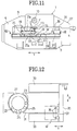
- As shown in FIG. 11 and FIG. 12, a
side frame 5 and a side frame 7 are erected, one on each side of abase 3 of aturret punch press 1. An upper frame 9 is provided on the upper sides of theside frame 5 and the side frame 7. A verticallymovable ram 11 mounted on the upper frame 9 is moved by a mechanical vertically moving means such as acrank shaft 10. On the lower end of theram 11, astriker device 15 having apiston rod 13 is provided as a striker element, freely movable vertically by a hydraulic mechanism which will be described in detail hereinafter. - In addition, on the lower surface of the upper frame 9, a disk-shaped
upper turret 21 is rotatably supported by an upperrotary shaft 21a. Detachably mounted on the upper turret are a plurality of upper punching dies 17 and a plurality of upward-formingupper dies 19 as the upper dies. In FIG. 1, a plurality of punchingupper dies 17a is mounted in the radial direction of the upper turret 21 (the A direction in the drawing). Although not shown in the drawing, a plurality of upward-forming upper dies can also be mounted in the radial direction of the upper turret 21 (the A direction in the drawing) in place of the normalupper dies 19, in exactly the same manner as for the punching dies 17a. Each of thedies 17a is vertically movable independently of each other. Thedies 17a are adapted to be positioned in the operating position under theram 11. - Again referring to FIG. 11 and FIG. 12, a
lower turret 27 is rotatably supported by a lowerrotary shaft 27a on the upper surface of thebase 3 opposing theupper turret 21. Detachably mounted on the lower turret are a plurality of lower punching dies 23 and lower upward-forming dies 25 respectively as the lower dies opposing the upper punching dies 17 and the upper upward-forming dies 19, Although not shown on the drawings, when a plurality of upper dies 17a are provided in the radial direction of theupper turret 21. A plurality of lower dies (not shown) each corresponding to the upper dies 17a are provided on thelower turret 27 in the radial direction of thelower turret 27. - The
upper turret 21 and thelower turret 27 are synchronized and rotatably controlled by means of, for example, a turret servo motor (omitted from the drawings) mounted on theside frame 5. As a result, during the punching process, the desired upper punching dies 17 and the lower punching dies 23, and, in addition, during the upward forming process, the upper upward-forming dies 19 and the lower upward-forming dies 25, are selectively positioned at the working area immediately under theram 11. - On the upper surface of the
base 3, a pair ofguide rails 29 each extending in the Y-axis direction are juxtaposed in the direction perpendicular to the plane of the drawing in Fig. 11 (only one of therails 29 is shown in Fig. 11). A pair of movable tables 33, positioned one on each of the front and back sides of a fixed table 31 secured on thebase 3, are movably supported on the guide rails 29. The movable tables 33 are integrally mounted on acarriage base 35 extending in the X-axis direction over the fixed table 31. In addition, acarriage 37 which moves in the longitudinal direction (the X-axis direction) crossing the direction of motion of the movable table 33 (the Y-axis direction in the drawings) is mounted on thecarriage base 35. Aclamp 39 which clamps one end of a plate-shaped workpiece W is movably mounted in the X-axis direction on thecarriage 37. - Accordingly, to position the workpiece W, the movement of the
carriage 37, on which is mounted theclamp 39 for clamping one end of a plate-shaped workpiece W, is performed in the X-axis direction along thecarriage base 35, and the movement of thecarriage 35 is performed in the Y-axis direction along the guide rails 29. - As shown in FIG. 1 to FIG. 3, a
ram guide 41 is provided on the upper frame 9 for moving theram 11 vertically. Furthermore, a channel-shapedguide 43 opened downward is installed on the bottom surface of theram 11 by means of abolt 45, extending in the radial direction of the upper turret 21 (the A direction in the drawings). A cylinder bracket 47 (Fig. 3) is installed by means of abolt 49 on the upper end of theguide 43 in FIG. 3. A fixedhydraulic cylinder 51 is securely installed on both thecylinder bracket 47 and theguide 43 on the upper end section of theguide 43 in Fig. 3. Accordingly, theguide 43, thecylinder bracket 47, and the fixedhydraulic cylinder 51 do not move with respect to theram 11. In addition, a movablehydraulic cylinder 53 opposing the fixedhydraulic cylinder 51 is provided in a manner allowing free movement along theguide 43. The tip of a piston rod 51a of the fixedhydraulic cylinder 51 and the tip of apiston rod 53a of the movablehydraulic cylinder 53 are linked by a joint 55. The bottom surface of the movablehydraulic cylinder 53 is secured to a connectingmember 59, fastened by abolt 57 to the left end of thestriker device 15. - Accordingly, by feeding an operating fluid from a
tube 61 of the fixed and movablehydraulic cylinders tube 63, the piston rod 51a of the fixedhydraulic cylinder 51 is projected to the left and thepiston rod 53a of the movablehydraulic cylinder 53 is projected to the right in Fig. 3. As a result, themovable cylinder 53 pulls thestriker device 15 to the left in FIG. 3 through the connectingmember 59. Conversely, by feeding the operating fluid from thetube 63 into the cylinder chamber and discharging it from thetube 61, the piston rod 51a of the fixedhydraulic cylinder 51 is moved to the right and thepiston rod 53a of the movablehydraulic cylinder 53 to the left in Fig. 3. Then, themovable cylinder 53 moves thestriker device 15 to the right in FIG. 3 through the connectingmember 59. - Referring to Figs. 1-3, a
hydraulic cylinder 65 is provided in thestriker device 15 as a hydraulic striker cylinder with apiston rod 67 projecting freely downward. As described above, thepiston rod 67 is selectively positioned above the normal upper dies 17, 19 or above a specificupper die 17a provided in the radial direction of theupper turret 21 by moving and positioning thestriker device 15. Here, because thepiston rod 67 strikes the upper surface of the upper dies 17, 17a, 19 while projecting downward, the stroke length for the vertical movement of the tip of thepiston rod 67 is the sum of the stroke length of theram 11 itself and the stroke length of thepiston rod 67 of thehydraulic striker cylinder 65. - An
air blower 69 is provided at the center of the bottom surface of thepiston rod 67. Thus, compressed air supplied from a tube d1 (see FIG. 4 and FIG. 5) is fed from the side surface of the cylinder chamber to the inside of thepiston rod 67. This compressed air is blown out of discharge ports (not shown) in the lower surfaces of the upper dies 17, 19, so that the workpiece W is easily separated from the upper dies 17. 19 and the scrap is easily removed from the upper dies 17, 19. - A
proximity switch 71 for detecting the vertical movement of thepiston rod 67 is provided on thepunching device 15 in the vicinity of thepiston rod 67. Theswitch 71 detects the vertical position of thepiston rod 67, and detects whether thepiston rod 67 has reached the top and bottom dead center in the conventional manner. - Next, the hydraulic mechanism of the punching
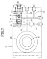
hydraulic cylinder 65 will be explained, referring to FIG. 4 to FIG. 7. A tube b₁ is provided to feed operating fluid to anupper cylinder chamber 73 of the punchinghydraulic cylinder 65 to move thepiston rod 67 downward. One end of the tube b₁ is open to theupper cylinder chamber 73 and the other end is open to the right side end surface of thestriker device 15. In addition, when the operating fluid from the tube b₁ is fed into theupper cylinder chamber 73, the operating fluid in alower cylinder chamber 75 is discharged by the upward movement of thepiston rod 67. A tube b₂ is provided parallel to the tube b₁ to feed operating fluid to thelower cylinder chamber 75 to elevate thepiston rod 67. One end of the tube b₂ is open to thelower cylinder chamber 75 and the other end is open to the right end surface of thestriker device 15. A tube c₂ connected to amanual valve 77 is provided on the tube b1 in a position close to the punchinghydraulic cylinder 65, extending in the direction perpendicular to the extension of the tube b₁. Further, a tube a₂ connected to a switchingvalve 79 is provided on the tube b1 in a position close to the vicinity of the right end surface of thedevice 15, extending in the direction perpendicular to the extension of the tube b₁. The switchingvalve 79 is for controlling the flow of the operating fluid. An end of thevalve 79 is mounted on the right end surface of thestriker device 15 as a port b₄. A tube a₁ connected to the switchingvalve 79 is provided in a position close to the punchinghydraulic cylinder 65 on the tube b2. A tube b₃ is coupled to a tube c₁ which is connected to the switchingvalve 79. One end of the tube b₃ opens to the right end surface of thestriker device 15. - Control of the punching
hydraulic cylinder 65 will now be explained with reference to the above-mentioned figures and FIG. 8. In the case where thepiston rod 67 is lowered, as shown by the white arrows in FIG. 8, when operating fluid is fed from the b₃ port this operating fluid flows into the switchingvalve 79 through the tube c₁, and a pressure is applied to a chamber D (Fig. 7) to open a valve B (Fig. 7). As a result, the operating fluid flows from the tube a₂ into the tube b₁ and into theupper cylinder chamber 73, and thepiston rod 67 is lowered. At this time, the operating fluid in thelower cylinder chamber 75 passes through the tube b₂ and is discharged from the b₂ port. - Conversely, in the case where the
piston rod 67 is elevated, when operating fluid is fed from the b₂ port, as shown by the black arrows in FIG. 8, this operating fluid flows into thelower cylinder chamber 75 and thepiston rod 67 is elevated. Because the operating fluid also flows into the tube a₁ at the same time, a spool A (Fig. 7) of the switchingvalve 79 is moved to the right and the valve B (Fig. 7) is opened. As a result, along with the elevation of thepiston rod 67, the operating fluid in theupper cylinder chamber 73 is pushed out into the tube b₁ by back pressure, flows from the tube a₂ through the valve B into the tube c₁, passes through the tube b₃, and is discharged from the b₃ port. - In addition, where the operating fluid is fed to neither the b₂ port or the b₃ port, when an upward external force (a reaction force which strikes the upper dies 17, 19, during processing) is applied to the
piston rod 67, the operating fluid in theupper cylinder chamber 73 tends to pass through the tube b₁ and flow into the tube a₂. However, no such flow will take place because the valve B of the switchingvalve 79 is closed. Accordingly, because thepiston rod 67 is not moved vertically, the upper dies 17, 19 can be struck. - As shown in FIG. 9 and FIG. 10, a
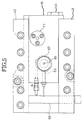
disk support 81 is secured to a section of the upper surface of thebase 3 under thelower turret 27 in the working area beneath theram 11, to prevent thelower turret 27 from vibrating during processing. Thisdisk support 81 has a pair ofsupport members 83 as reinforcing members and aslider 85 which moves horizontally between thesupport members 83. - The leading end of a
piston rod 89 of ashift cylinder 87 is attached to the right end surface of theslider 85 in the Figs. 9 and 10. Theslider 85 is provided on the upper surface of aguide 91 which is in turn provided on the upper surface of thebase 3. Theslider 85 is moved along a path between thesupport members 83 by the horizontal movement of thepiston rod 89. Aresidue hole 93 through which a residue produced by the punching process is discarded, is formed at a position corresponding to the working area under theram 11. Aresidue disposal guide 95 with a suitable hole for discarding the residue is provided in the left half section of theslider 85. Afluid cylinder 97 is provided as a forming cylinder in the right half section of theslider 85 for pressing the lower upward-formingdie 25 upward. - The lower upward-forming
die 25 includes a verticallymovable die holder 99, adie tip 101 integrally provided in thedie holder 99, and aworkpiece ejector 103 vertically movable with respect to thedie tip 101. The upper end of the die tip 102 is adapted to engage the upper upward-forming die 19 (FIG. 11). Theworkpiece ejector 103 is urged upward with respect to thedie tip 101 by aspring 105. Thus, when the forming process has been completed and thedie tip 101 is moved downward, the workpiece W is easily separated from thedie tip 101 by the upward movement of thework ejector 103 relative to thedie tip 101. - In addition, a
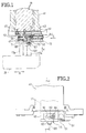
piston rod 107 of the formingcylinder 97 is freely movable in the vertical direction. Therefore, by feeding operating fluid from a tube e₁ to anupper chamber 97a of the formingcylinder 97, thepiston rod 107 is retracted into thecylinder 97 so that the upper end of thedie tip 101 does not project above a pass-line L of the workpiece. On the other hand, by feeding the operating fluid from a tube e2 to alower chamber 97b of the formingcylinder 97, thepiston rod 107 is moved upward so that thedie holder 99 is pressed upward and the upper end of thedie tip 101 is projected above the pass-line L. Thus, a forming processing is performed. After the processing, the workpiece W which may be engaged by thedie tip 101, can be removed from thedie tip 101 by the upward movement of theworkpiece ejector 103. - During periods other than the upward-forming process periods, the
piston rod 107 is retracted into the formingcylinder 97. Therefore thepiston rod 107 does not project upward from the upper surface of theslider 85. Specifically, the rotary positioning of thelower turret 27 and the movement of theslider 85 are performed while thepiston rod 107 is retracted into the formingcylinder 97. Thus, there is no obstacle to the movement of theslider 85. - Now, the operations of the turret punch press will be described in detail.
- First, as shown in FIG. 11 and FIG. 12, a workpiece W to be processed is clamped by the
clamps 39 on thecarriage 37. Then, the part of the workpiece W is positioned in the working area between theupper turret 21 and thelower turret 27 by controlling the movement of thecarriage 37 in the X-axis direction along thecarriage base 35, and by controlling the movement of thecarriage base 35 in the Y-axis direction along the guide rails 29. - The
upper turret 21 and thelower turret 27 are rotated in synchronism by a turret servo motor and the specified upper and lower punching dies 17, 23 are positioned in the working area. As shown in FIG. 1, in the case where the plurality of the upper punching dies 17a provided in the radial direction of theupper turret 21 is to be used, the punchingdevice 15 is positioned above the desireddie 17a by means of the fixedhydraulic cylinder 51 and the movablehydraulic cylinder 53. Thepiston rod 67 of thehydraulic striker cylinder 65 is projected downward and halted at bottom dead center. Thepiston rod 89 of theshift cylinder 87 provided in thedisk support 81 is drawn back, and theresidue disposal guide 95 of theslider 85 is positioned in the working area. - Then, the
ram 11 is moved downward by the action of thecrank shaft 10 acting as the mechanical type of vertically moving means, and thepiston rod 67 of thehydraulic striker cylinder 65 strikes the upper punching dies 17, 17a to carry out a punching process. The punched residue drops downward through theresidue disposal guide 95 and theresidue hole 93. - Thereafter, the workpiece W is once again positioned, the above-mentioned process is repeated, so that a required series of punching operations are performed in the workpiece. During the
turrets piston rod 67 of thehydraulic striker cylinder 65 is preferably retracted; with this retraction, thepiston rod 67 is prevented from being collide with by the head of an upper punching die. - The above embodiment is advantageous in that it is unnecessary to operate the
hydraulic striker cylinder 65 during the punching process since thepiston rod 67 of thehydraulic striker cylinder 65 is fixed at bottom dead center during the punching process. Therefore the frequency of use is reduced and the life span is increased. - Furthermore, the
striker device 15 provided on the lower end of theram 11 is freely moved and positioned in the radial direction ofupper turret 21, so that a plurality of upper dies can be mounted in the radial direction on theupper turret 21. For this reason, the number of dies which can be installed is increased and the effectiveness of the operation is improved. - When an upward-forming process is performed in the workpiece W, a part of the workpiece W to be processed is positioned in the working area between the
upper turret 21 and thelower turret 27 in the same manner as for the above-described punching process. Then, by controlling the rotation of theupper turret 21 and thelower turret 27, the desired upper upward-formingdie 19 and lower upward-formingdie 25 are positioned in the working area. Here, if a plurality of upper upward-forming dies provided in the radial direction of theupper turret 21 are to be used, thestriker device 15 is positioned directly above the desired die by the fixedhydraulic cylinder 51 and the movablehydraulic cylinder 53. - The
piston rod 89 of theshift cylinder 87 is extended, and the formingcylinder 97 of theslider 85 is positioned in the working area. In this way, the workpiece W is positioned and the upper and lower dies 19, 25 are set. - As shown in FIGS. 13 and 14, the
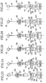
crank shaft 10 is then rotated so that the piston rod (striker element) 67 and theupper die 19 are moved downward until the lower end of theupper die 19 is positioned just above the surface of the workpiece W. Here, it is to be noted that in the press shown in FIGS. 13-18, anelastic member 201 is provided under thedie holder 99 for a purpose mentioned hereinafter. - As shown in FIG. 15, subsequently, the
striker cylinder 65 is energized so that theupper die 19 is further moved downward until the lower end of the upper die is in contact with the surface of the workpiece W. - As shown in FIG. 16, the lower cylinder (forming cylinder) 97 is then energized so that the
lower die 25 is moved upward. As a result, an upward forming is performed in the workpiece W by thedie tip 101 of thelower die 25. Here, it is to be noted that the impulse force from die tip 102 on the workpiece W is buffered by theelastic member 201. - As shown in FIG. 17, the
lower cylinder 97 is then de-energized, and thelower die 25 is moved downward by the restoring force of theelastic member 201 and the spring 105 (FIG. 10). - As shown in FIG. 18, the
upper die 19 is subsequently moved upward to return its original position by the rotation of thecrank shaft 10 and the upward movement of theupper cylinder 65. - It is now understood that in this embodiment, the workpiece W is maintained in its original height during forming. Thus, the workpiece is prevented from being damaged during the processing.
- Furthermore, in the above embodiment, since the height of the
upper die 19 can be adjusted within the stroke length of thestriker cylinder 65, the forming in the workpieces W with different thickness can be easily performed; this is because, the workpieces W with different workpieces can be maintained in their respective original height during forming by adjusting the height of the lower end of theupper die 19. - In the above embodiments, the forming
cylinder 97 is built into the right half of theslider 85 of the above-mentioned embodiment and theresidue disposal guide 95 is provided on the left half. In addition, theshift cylinder 87 is provided on the right side surface of theslider 85. However, the present invention is not limited to this positional relationship. Further, although thehydraulic shift cylinder 87 is used for moving theslider 85, the present invention is not limited to this configuration. For example, a combination of a drive motor and a geared device may be used. - Because the turret punch press of the present embodiment has a configuration as explained above, and the striker device with a hydraulic cylinder equipped with a vertically movable striker element on the lower end of the ram is provided, the amount of stroke of the striker element with respect to the upper die is the sum of the amount of stroke of the ram and the amount of stroke of the hydraulic cylinder. Accordingly, the upper die contacts the lower die and processing can occur only when the ram and the striker element of the striker device are both at bottom dead center. Accordingly, during the punching process, the striker element of the striker device is normally positioned at bottom dead center, and, if the ram is lowered by the mechanical vertically moving means, the action of the hydraulic cylinder is unnecessary. Therefore the frequency of use is reduced, and the life span is increased. In addition, after the ram is lowered by the mechanical vertically moving means during the forming process. if the striker element of the hydraulic cylinder is lowered and the forming operation is performed, even if the ram Is lowered rapidly by the mechanical vertically moving means, the upper die does not reach bottom dead center, therefore there is no impact on the lower die so no breakage or damage occurs. In addition, the adjustment of the height of the upper and lower dies need not be scrupulously performed as is required conventionally so operability is improved. In addition, because the disk support is secured below the lower turret, it is possible to support the lower turret against the striking force in the conventional manner. The movably positioned slider is provided in the disk support, and because the hydraulic cylinder which presses the lower upward-forming die upward and the residue hole through which the residue from the punching operation is dropped are provided, the hydraulic cylinder during the upward-forming process, or the residue hole during the punching process, can be selectively positioned at the process position. As a result, it is possible to handle both the upward-forming process and the punching process. Here, the lower upward-forming die is normally below the pass line so that there is no obstacle when the lower turret rotates or when the workpiece is introduced. Because the hydraulic cylinder projects the lower upward-forming die upward to a position of a specified height during processing, a proper upward-forming process can be performed.
- FIGS. 19-26 shows the second embodiment of the present invention.
- As shown in FIGS. 25 and 26, a
turret punch press 201 of the second embodiment is generally similar to that of the first embodiment. That is to say, thepress 201 comprises abase 203, side frames 205, 207 provided on both sides of thebase 203, and anupper frame 209 provided on the side frames 205, 207. A disk-likeupper turret 211 is rotatably supported by anupper rotation axis 215a under theupper frame 209. A plurality ofupper tools 211 for punching a workpiece W andupper tools 213 for forming of the workpiece W are removably installed on theupper turret 211. A disk-likelower turret 221 is rotatably supported by anlower rotation axis 221a in a way opposing theupper turret 211 and above thebase 203. A plurality oflower tools 217 for punching the workpiece W andlower tools 219 for forming of the workpiece W are removably installed on thelower turret 221. Adisc support 223 is secured on thebase 203 under thelower turret 221. Aram 227 having astriker 225 for striking theupper tools upper frame 209. - The upper and
lower turrets lower tools lower tools - A pair of
guide rails 229 extending in the Y direction (FIG. 25) are provided on thebase 203. A pair of movable tables 233 are positioned, one on each side of a fixed table 231, and supported on the guide rails 229. The movable tables 233 are attached to acarriage base 235 extending in the X direction (FIG. 26) bridging the fixed table 231. Acarriage 237 movable in the X direction perpendicular to the moving direction of the movable table 233 (Y direction) is provided on thecarriage base 235. Thecarriage 237 is provided with aclamp device 239 for clamping an edge of the workpiece W. - Thus, positioning of the workpiece W is controlled by moving the
carriage 237 in the X direction and by moving thecarriage 237 on theguide rail 229 in the Y direction. - As shown in FIGS. 23 through 26, a plurality of
upper tools 211 for punching are removably installed on theupper turret 215, and a plurality ofupper tools 213 for forming are removably installed in tool installation holes 241 in theupper turret 215. The configuration of theupper tool 211 for punching is well known in the art, and therefore will not be described in detail. Theupper tool 213 for forming is provided with apunch body 243 with arecess 245 at its lower end. Thepunch body 243 has aflange 247 at its upper end. Aspring 249 which normally presses theflange 247 upward is provided between theflange 247 and theupper turret 215. Thepunch body 243 is slidably installed in apunch guide 251 mounted on theupper turret 215. Thepunch body 243 is supported by aspring 253 at the upper end of thepunch guide 251. The spring constant of thespring 253 is larger than that of thespring 249. Aflange 255 is formed in a way projecting outward from the upper end of thepunch guide 251 to keep thepunch guide 251 from dropping through thehole 241. - A plurality of
lower tools 217 for punching are removably installed on thelower turret 221; a plurality oflower tools 219 for forming are removably installed in tool installation holes 257 in thelower turret 221. The configuration of thelower tool 217 for punching is well known in the art, and therefore will not be described in detail. Thelower tool 219 for forming comprises adie holder 259, adie chip 261 integrally formed on the die holder and adapted to be inserted into therecess 245 of thepunch body 243, and awork ejector 263 vertically movable with respect to thedie chip 261. Aspring 267 is provided between thework ejector 263 and thedie holder 259 to push up theejector 263. Aspring 269 is provided between thedie holder 259 and aflange 265 formed in thetool installation hole 257, to push down thedie holder 259. Thus, thelower tool 219 in a normal state is below the pass line PL (the feed line for the workpiece W). - As shown in FIGS. 19 through 22, the
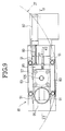
disc support 223 includes a hollow rectangular parallelepiped block with apertures on the right side and on the upper and lower sides. Bothside walls lower turret 221 from the underside. The thickness of theside walls - The
disc support 223 contains a freely reciprocatingmovable block 271. The left end of themovable block 271 is connected to apiston rod 275 of aslide cylinder 273. Themovable block 271 is formed as a rectangular parallelepiped to fit the inside configuration of thedisc support 223. A throughhole 277, through which punched scraps are dropped, is provided on the right half of themovable block 271. Apress cylinder 279 with apiston rod 281 is embedded in the left half of themovable block 271 as means for pushing up thelower tool 219 for forming. A top 281a of thepiston rod 281 pushes up thedie holder 259, causing thelower tool 219 to project above the pass line PL (FIG. 24). During the punching operation, thepiston rod 281 is retracted into thepress cylinder 279, so that thelower tool 219 does not project above the pass line PL (FIG. 23). - In operation, as shown in FIGS. 25 and 26, the
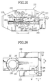
carriage 237 clamping the workpiece W moves in the X direction on thecarriage base 235. In addition, thecarriage base 235 moves on theguide rails 229 in the Y direction, so that the part of the workpiece W to be processed is positioned in the working area between the upper andlower turrets - In the punching operation, as shown in FIGS. 19 and 20, the desired upper and
lower tools lower turrets piston rod 275 of theslide cylinder 273 is then retracted to move the movable block to position the throughhole 277 in the working area, after which the striker 225 (FIG. 25) strikes theupper tool 211 to perform the punching in a workpiece. The punched scraps drop down through the throughhole 277. - In the forming operation, as shown in FIGS. 21 and 22, the part of the workpiece W to be processed is positioned in the working area between the upper and
lower turrets lower turrets - The
piston rod 275 of theslide cylinder 273 is extended to move themovable block 271 to position thepress cylinder 279 in the working area.
The right end of themovable block 271 projects from the aperture at the right side of the disc support 223 (FIGS. 21 and 22).
At this stage, thepiston rod 281 of thepress cylinder 279 is retracted so that thelower tool 219 does not project above the pass line PL, as shown in FIG. 23. Thepiston rod 281 is then extended to push up thedie holder 259, as shown in FIG. 24, so that thelower tool 219 projects above the pass line PL. Thestriker 225 strikes the upper end of thepunch body 243 which descends accordingly together with thepunch guide 251. Thespring 253 also descends and is not compressed until theflange 255 of thepunch guide 251 comes into contact with the upper face of theupper turret 215. When thestriker 225 further descends, thepunch body 243 descends compressing thespring 253, and a forming is performed in the workpiece. - After completion of the forming process, the
striker 225 is elevated and thespring 253 extends by its restoring force to press up thepunch body 243. Thestriker 225 further ascends and then thespring 249 extends to raise thepunch body 243 with thepunch guide 251. On the other hand, thepiston rod 281 of thepress cylinder 279 is retracted and thedie holder 259 with thedie chip 261 is pressed down by the restoring force of thespring 269. Consequently, thework ejector 263 is raised with respect to thedie holder 259 by the restoring force of thespring 267, thereby pushing up the workpiece W and releasing it from thedie chip 261. - Alternatively, it is to be understood that after positioning the upper and
lower tools striker 225 can descend to the original bottom dead point so that theupper tool 213 abuts the upper surface of theupper turret 215. Thereafter thepiston rod 281 of thepress cylinder 279 can be extended to push up thedie holder 259 to perform forming of the workpiece W. That is, pushing up thelower tool 219 for forming is equivalent to lowering thestriker 225 with respect to thelower tool 219. Thestriker 225 is vertically actuated by a hydraulic cylinder. - According to the above embodiment, the
disc support 223 is secured to the base 203 in the working area and the thickness of theside walls upper turret 221 is reliably supported during striking. Further, since the position of the lower tool is not changed with respect to theupper turret 215 and theupper tools - The upper and
lower turrets turrets disc support 223 contains themovable block 271 having thepress cylinder 279 to push up thelower tool 219, and the throughhole 277 through which punched scraps are discharged. This means that thedisc support 223 functions as both a support for the lower turret and a push-up means for the lower tool. If a support for the lower turret and a push-up means for the lower tool were provided separately, a changing operation would be required. According to the invention, however, punching and forming can be performed without such a changing operation. - The workpiece W can be processed without damage since the
lower tool 219 for the forming, is normally below the path line PL and therefore does not interfere with the positioning operation of the workpiece W. When the turrets rotate after positioning the workpiece W in the working area, the workpiece W does not interfere with the lower tool for forming. Accordingly, the workpiece remains level, thus the workpiece W is properly processed. - While the above embodiment has been described with the
movable block 271 with the throughhole 277 on its right and the press cylinder on its left, and with theslide cylinder 273 at the left side, it should be understood that any other arrangement can be employed. Further, while theslide cylinder 273 is used to move themovable block 271, any other suitable means to control the positioning of themovable block 271, for example, a drive motor combined with a gear assembly could be employed.
Claims (10)
- A press comprising:
a frame (3, 5, 7, 9) having a base frame (3), side frames (5, 7) and an upper frame (9);
upper (17, 19) and lower (23, 25) dies mounted respectively on the upper frame (9) and the base frame (3) in such a way to oppose to each other, the upper and lower dies being adapted to be slidable in the vertical direction so as to cooperate with each other to perform a processing in a workpiece (W) provided therebetween;
a striker (67) mounted on the upper frame (9) so as to move in the vertical direction and adapted to be in contact with the head of the upper die (17, 19);and,
upper drive means (10, 11, 65) mounted on the upper frame (9) for causing the striker (67) to move in the vertical direction, the upper drive means including a vertically movable ram (11), characterized in that
a lower drive means (97) is mounted on the base frame (3), is adapted to cause the lower die (23, 25) to move downward and upward and is also adapted to be, in its retracted downward position, horizontally movable so that the lower drive means (97) can be positioned horizontally away from the processing position under the ram (11) . - The press of claim 1, wherein the upper drive means (10, 11, 65) is adapted to stop the striker (67) at a selectable vertical position.
- The press of claim 1 or 2, wherein the upper drive means (10, 11, 65) includes:
a mechanical vertically moving means (10) mounted on the upper frame (9), the ram (11) being coupled to the mechanical vertically moving means (10) so as to be driven by the mechanical vertically moving means (10); and a sub-upper-drive means (65) mounted on the ram (11) for moving the striker (67) relative to the ram (11). - The press of claim 3, wherein at last one of the lower drive means (97) and the sub-upper-drive means (65) includes a hydraulic cylinder.
- The press of any of the preceding claims, wherein upper drive means (10, 11, 65) is adapted to fix the striker (67) in the vertical direction at a height corresponding to the height of the upper die (17, 19) where the lower end of the upper die (17, 19) is on the pass-line (PL) of the work piece (W).
- The press according to claim 1, wherein lower drive means (97) of the lower die (23, 25) are contained in a freely movable slider (85) which moves horizontally on the upper surface of a guide (91) provided on the base frame (3).
- The press according to claim 6, wherein the slider (85) includes:
a first half section with a residue disposal guide (95) containing a hole for discarding the residue; and,
a second half section which comprises the lower drive means (97), the first and second half sections being positioned at the processing position under the ram (11), respectively to perform a punching or an upward-forming operation. - The press according to claim 6 or 7, wherein the lower drive means (97) comprises an hydraulic fluid cylinder (97) with a vertically movable piston rod (107) adapted to cause the lower die (23, 25) to move up and down.
- The press according to claim 6, wherein the slider (85) is attached to the leading end of a horizontal piston rod (89) of a shift cylinder (87).
- The press according to claim 1, 4, 6 or 8, wherein the lower die (23, 25) includes a die tip (101) integrally provided in a die holder (99) and a workpiece ejector (103) vertically movable with respect to the die tip (101).
Applications Claiming Priority (5)
| Application Number | Priority Date | Filing Date | Title |
|---|---|---|---|
| US07/807,586 US5177843A (en) | 1991-12-16 | 1991-12-16 | Turret punch press |
| US807586 | 1991-12-16 | ||
| US07/838,867 US5184498A (en) | 1992-02-21 | 1992-02-21 | Turret punch press |
| US838867 | 1992-02-21 | ||
| EP19920403431 EP0555604B1 (en) | 1991-12-16 | 1992-12-16 | Turret punch press |
Related Parent Applications (3)
| Application Number | Title | Priority Date | Filing Date |
|---|---|---|---|
| EP92403431.7 Division | 1992-12-16 | ||
| EP19920403431 Division EP0555604B1 (en) | 1991-12-16 | 1992-12-16 | Turret punch press |
| EP19920403431 Division-Into EP0555604B1 (en) | 1991-12-16 | 1992-12-16 | Turret punch press |
Publications (2)
| Publication Number | Publication Date |
|---|---|
| EP0694347A1 true EP0694347A1 (en) | 1996-01-31 |
| EP0694347B1 EP0694347B1 (en) | 2000-10-11 |
Family
ID=27123030
Family Applications (2)
| Application Number | Title | Priority Date | Filing Date |
|---|---|---|---|
| EP19920403431 Expired - Lifetime EP0555604B1 (en) | 1991-12-16 | 1992-12-16 | Turret punch press |
| EP95114957A Expired - Lifetime EP0694347B1 (en) | 1991-12-16 | 1992-12-16 | Turret punch press |
Family Applications Before (1)
| Application Number | Title | Priority Date | Filing Date |
|---|---|---|---|
| EP19920403431 Expired - Lifetime EP0555604B1 (en) | 1991-12-16 | 1992-12-16 | Turret punch press |
Country Status (4)
| Country | Link |
|---|---|
| EP (2) | EP0555604B1 (en) |
| CA (1) | CA2085545A1 (en) |
| DE (2) | DE69210210T2 (en) |
| FI (2) | FI106187B (en) |
Families Citing this family (6)
| Publication number | Priority date | Publication date | Assignee | Title |
|---|---|---|---|---|
| IT1278354B1 (en) * | 1995-02-06 | 1997-11-20 | Sapim Amada Spa | PROCEDURE AND MACHINE FOR THE PRODUCTION OF SHEET METAL PANELS. |
| IT1278355B1 (en) * | 1995-02-06 | 1997-11-20 | Sapim Amada Spa | FOLDING EQUIPMENT FOR SHEETS. |
| ATE515336T1 (en) | 2008-10-20 | 2011-07-15 | Trumpf Werkzeugmaschinen Gmbh | MACHINE TOOLS AND METHOD FOR EXHAUSTING A PART OF A WORKPIECE |
| CN112808915B (en) * | 2020-12-23 | 2023-03-24 | 青岛宏源泰机械有限公司 | Hydraulic forging machine capable of achieving continuous impact |
| CN114951072B (en) * | 2022-06-21 | 2023-08-01 | 广东天众模具科技有限公司 | Stamping drawing die |
| CN115555453B (en) * | 2022-11-04 | 2023-07-04 | 武汉聚鹏精密制造有限责任公司 | Stamping device is used in production of automobile punching part |
Citations (1)
| Publication number | Priority date | Publication date | Assignee | Title |
|---|---|---|---|---|
| WO1990005601A1 (en) | 1988-11-18 | 1990-05-31 | Amada Company, Limited | Turret punch press |
Family Cites Families (4)
| Publication number | Priority date | Publication date | Assignee | Title |
|---|---|---|---|---|
| US2581435A (en) * | 1948-03-31 | 1952-01-08 | Nowak Alois Karl | Press with mechanical drive having harmonic motion and hydraulic transmission |
| US3005404A (en) * | 1959-09-01 | 1961-10-24 | Tucker & Sons | Hydraulic connecting unit for punch-press rams |
| US3685380A (en) * | 1971-02-19 | 1972-08-22 | Amada Ltd Us | Multi-track turret and overload protection |
| JPS60141339A (en) * | 1983-12-28 | 1985-07-26 | Nissan Motor Co Ltd | Reverse drawing press device |
-
1992
- 1992-12-15 FI FI925689A patent/FI106187B/en not_active IP Right Cessation
- 1992-12-16 DE DE1992610210 patent/DE69210210T2/en not_active Expired - Lifetime
- 1992-12-16 EP EP19920403431 patent/EP0555604B1/en not_active Expired - Lifetime
- 1992-12-16 EP EP95114957A patent/EP0694347B1/en not_active Expired - Lifetime
- 1992-12-16 DE DE1992631504 patent/DE69231504T2/en not_active Expired - Lifetime
- 1992-12-16 CA CA002085545A patent/CA2085545A1/en not_active Abandoned
-
2000
- 2000-09-06 FI FI20001969A patent/FI112452B/en not_active IP Right Cessation
Patent Citations (1)
| Publication number | Priority date | Publication date | Assignee | Title |
|---|---|---|---|---|
| WO1990005601A1 (en) | 1988-11-18 | 1990-05-31 | Amada Company, Limited | Turret punch press |
Also Published As
| Publication number | Publication date |
|---|---|
| CA2085545A1 (en) | 1993-06-17 |
| FI925689A (en) | 1993-06-17 |
| FI106187B (en) | 2000-12-15 |
| FI925689A0 (en) | 1992-12-15 |
| DE69231504D1 (en) | 2000-11-16 |
| EP0694347B1 (en) | 2000-10-11 |
| DE69210210T2 (en) | 1996-10-31 |
| FI20001969A (en) | 2000-09-06 |
| DE69210210D1 (en) | 1996-05-30 |
| DE69231504T2 (en) | 2001-05-10 |
| EP0555604A2 (en) | 1993-08-18 |
| EP0555604B1 (en) | 1996-04-24 |
| EP0555604A3 (en) | 1993-12-22 |
| FI112452B (en) | 2003-12-15 |
Similar Documents
| Publication | Publication Date | Title |
|---|---|---|
| KR101843193B1 (en) | Device for removing precision punching respectively fine blanking parts from a tool of a press | |
| US7325581B2 (en) | Apparatus for punching and welding or bonding workpieces | |
| US5247862A (en) | Process for producing burr-free workpieces by blanking, in particular in a counterblanking tool | |
| US5049054A (en) | Press having a tool mount to be inserted into the press | |
| GB2086786A (en) | Apparatus for flanging the edges of holes in workpieces on a piercing press | |
| EP0555604B1 (en) | Turret punch press | |
| JPS59102509A (en) | Double-acting multihead type drilling and slotting device | |
| CN114406776A (en) | Drilling machine with automatic discharging function | |
| US6993952B2 (en) | Multipurpose horizontal press having a fixed workpiece-holder for a tubular workpiece to be drawn or tapered | |
| US5184498A (en) | Turret punch press | |
| CN211464476U (en) | High-efficient stamping equipment | |
| JP7051825B2 (en) | Tools and tool machines and methods for cutting and / or deforming plate features | |
| JPH07256357A (en) | Compound press | |
| JP4513995B2 (en) | Turret punch press and processing method using the turret punch press | |
| JP2001001157A (en) | Press equipped with welding equipment | |
| US5177843A (en) | Turret punch press | |
| CN116021266B (en) | Automatic feeding and riveting equipment for chassis screws of multi-specification air conditioner outdoor unit | |
| JP4008518B2 (en) | Horizontal rough trimming device for die casting machine | |
| CN218693049U (en) | Wood grain aluminum single plate tower punching equipment | |
| CN218310479U (en) | Stamping lathe is used in die casting production | |
| CN220311494U (en) | Porous perforating device of work piece | |
| CN218555303U (en) | Automatic punching machine for junction box | |
| SU1426686A1 (en) | Die for extrusion of flanged parts | |
| CN210754633U (en) | Floating opposite punching die | |
| JPH03133527A (en) | Punch press |
Legal Events
| Date | Code | Title | Description |
|---|---|---|---|
| PUAI | Public reference made under article 153(3) epc to a published international application that has entered the european phase |
Free format text: ORIGINAL CODE: 0009012 |
|
| AC | Divisional application: reference to earlier application |
Ref document number: 555604 Country of ref document: EP |
|
| AK | Designated contracting states |
Kind code of ref document: A1 Designated state(s): DE FR GB IT |
|
| 17P | Request for examination filed |
Effective date: 19960724 |
|
| 17Q | First examination report despatched |
Effective date: 19980407 |
|
| GRAG | Despatch of communication of intention to grant |
Free format text: ORIGINAL CODE: EPIDOS AGRA |
|
| GRAG | Despatch of communication of intention to grant |
Free format text: ORIGINAL CODE: EPIDOS AGRA |
|
| GRAH | Despatch of communication of intention to grant a patent |
Free format text: ORIGINAL CODE: EPIDOS IGRA |
|
| GRAH | Despatch of communication of intention to grant a patent |
Free format text: ORIGINAL CODE: EPIDOS IGRA |
|
| GRAA | (expected) grant |
Free format text: ORIGINAL CODE: 0009210 |
|
| AC | Divisional application: reference to earlier application |
Ref document number: 555604 Country of ref document: EP |
|
| AK | Designated contracting states |
Kind code of ref document: B1 Designated state(s): DE FR GB IT |
|
| ITF | It: translation for a ep patent filed |
Owner name: JACOBACCI & PERANI S.P.A. |
|
| REF | Corresponds to: |
Ref document number: 69231504 Country of ref document: DE Date of ref document: 20001116 |
|
| ET | Fr: translation filed | ||
| PLBE | No opposition filed within time limit |
Free format text: ORIGINAL CODE: 0009261 |
|
| STAA | Information on the status of an ep patent application or granted ep patent |
Free format text: STATUS: NO OPPOSITION FILED WITHIN TIME LIMIT |
|
| 26N | No opposition filed | ||
| REG | Reference to a national code |
Ref country code: GB Ref legal event code: IF02 |
|
| PGFP | Annual fee paid to national office [announced via postgrant information from national office to epo] |
Ref country code: IT Payment date: 20101221 Year of fee payment: 19 Ref country code: GB Payment date: 20101123 Year of fee payment: 19 |
|
| PGFP | Annual fee paid to national office [announced via postgrant information from national office to epo] |
Ref country code: FR Payment date: 20111108 Year of fee payment: 20 |
|
| PGFP | Annual fee paid to national office [announced via postgrant information from national office to epo] |
Ref country code: DE Payment date: 20111212 Year of fee payment: 20 |
|
| REG | Reference to a national code |
Ref country code: DE Ref legal event code: R071 Ref document number: 69231504 Country of ref document: DE |
|
| REG | Reference to a national code |
Ref country code: DE Ref legal event code: R071 Ref document number: 69231504 Country of ref document: DE |
|
| REG | Reference to a national code |
Ref country code: GB Ref legal event code: PE20 Expiry date: 20121215 |
|
| PG25 | Lapsed in a contracting state [announced via postgrant information from national office to epo] |
Ref country code: GB Free format text: LAPSE BECAUSE OF EXPIRATION OF PROTECTION Effective date: 20121215 |