EP0694020B1 - Rewinding machine and method for the formation of logs of web material with means for severing the web material - Google Patents
Rewinding machine and method for the formation of logs of web material with means for severing the web material Download PDFInfo
- Publication number
- EP0694020B1 EP0694020B1 EP94912672A EP94912672A EP0694020B1 EP 0694020 B1 EP0694020 B1 EP 0694020B1 EP 94912672 A EP94912672 A EP 94912672A EP 94912672 A EP94912672 A EP 94912672A EP 0694020 B1 EP0694020 B1 EP 0694020B1
- Authority
- EP
- European Patent Office
- Prior art keywords
- web material
- core
- machine according
- rewinding machine
- feeding
- Prior art date
- Legal status (The legal status is an assumption and is not a legal conclusion. Google has not performed a legal analysis and makes no representation as to the accuracy of the status listed.)
- Expired - Lifetime
Links
Images


Classifications
-
- B—PERFORMING OPERATIONS; TRANSPORTING
- B65—CONVEYING; PACKING; STORING; HANDLING THIN OR FILAMENTARY MATERIAL
- B65H—HANDLING THIN OR FILAMENTARY MATERIAL, e.g. SHEETS, WEBS, CABLES
- B65H19/00—Changing the web roll
- B65H19/22—Changing the web roll in winding mechanisms or in connection with winding operations
- B65H19/2238—The web roll being driven by a winding mechanism of the nip or tangential drive type
- B65H19/2269—Cradle
-
- B—PERFORMING OPERATIONS; TRANSPORTING
- B26—HAND CUTTING TOOLS; CUTTING; SEVERING
- B26D—CUTTING; DETAILS COMMON TO MACHINES FOR PERFORATING, PUNCHING, CUTTING-OUT, STAMPING-OUT OR SEVERING
- B26D2210/00—Machines or methods used for cutting special materials
- B26D2210/11—Machines or methods used for cutting special materials for cutting web rolls
-
- B—PERFORMING OPERATIONS; TRANSPORTING
- B65—CONVEYING; PACKING; STORING; HANDLING THIN OR FILAMENTARY MATERIAL
- B65H—HANDLING THIN OR FILAMENTARY MATERIAL, e.g. SHEETS, WEBS, CABLES
- B65H2301/00—Handling processes for sheets or webs
- B65H2301/40—Type of handling process
- B65H2301/41—Winding, unwinding
- B65H2301/417—Handling or changing web rolls
- B65H2301/418—Changing web roll
- B65H2301/4181—Core or mandrel supply
- B65H2301/41812—Core or mandrel supply by conveyor belt or chain running in closed loop
-
- B—PERFORMING OPERATIONS; TRANSPORTING
- B65—CONVEYING; PACKING; STORING; HANDLING THIN OR FILAMENTARY MATERIAL
- B65H—HANDLING THIN OR FILAMENTARY MATERIAL, e.g. SHEETS, WEBS, CABLES
- B65H2406/00—Means using fluid
- B65H2406/10—Means using fluid made only for exhausting gaseous medium
- B65H2406/11—Means using fluid made only for exhausting gaseous medium producing fluidised bed
- B65H2406/112—Means using fluid made only for exhausting gaseous medium producing fluidised bed for handling material along preferably rectilinear path, e.g. nozzle bed for web
-
- B—PERFORMING OPERATIONS; TRANSPORTING
- B65—CONVEYING; PACKING; STORING; HANDLING THIN OR FILAMENTARY MATERIAL
- B65H—HANDLING THIN OR FILAMENTARY MATERIAL, e.g. SHEETS, WEBS, CABLES
- B65H2408/00—Specific machines
- B65H2408/20—Specific machines for handling web(s)
- B65H2408/23—Winding machines
- B65H2408/235—Cradles
-
- B—PERFORMING OPERATIONS; TRANSPORTING
- B65—CONVEYING; PACKING; STORING; HANDLING THIN OR FILAMENTARY MATERIAL
- B65H—HANDLING THIN OR FILAMENTARY MATERIAL, e.g. SHEETS, WEBS, CABLES
- B65H2513/00—Dynamic entities; Timing aspects
- B65H2513/10—Speed
Definitions
- the invention refers to a surface rewinding machine and method for the formation of logs or rolls of web material wound on a central core.
- Such rewinding machines are well-known, described, for example, in U.S. Patents No. 4,487,377; 4,723,724; 4,327,877 and 4,828,195; U.K. Patent No. 2,105,688; and in EP-A-0 489 039.
- the present invention refers to a rewinding machine which includes a first winder roller on which the web material is fed; a second winder roller defining, with the first winder roller, a nip through which the core and the web material pass; means for feeding the web material to said nip; means for introducing a core on which the web material is to be wound; and a web material severing means cooperating with said first winder roller.
- a rewinder of this type is described, for example, in U.S. Patent 4,487,377.
- These rewinders are used for producing smaller-diameter logs or rolls of web material from large-diameter parent rolls.
- these machines are used in the paper converting industry to produce rolls of toilet paper, kitchen towels, all-purpose wipers and the like.
- the formed logs may be as long as 350 cm and only 10-15 cm in outer diameter, and are subsequently cut transversely to their axis to obtain small rolls which may be only 10-30 cm long.
- U.S. Patent 4,487,377 provides for a web-cutting member which cooperates with the first winder roller of the rewinder.
- the web material is cut upstream of the point where the core is introduced. After cutting, the leading edge of the web material adheres to the surface of the winder roller and is transferred (by the rotation of the latter) towards the winding region where the leading edge is made to adhere to a new core suitably introduced by an insertion means.
- This machine requires means (for holding the leading edge of the web material onto the winder roller) which are housed inside the winder roller and which must be timely activated and deactivated to hold and release the edge at preset moments, thereby allowing the starting of the winding on a new core.
- a first object of the present invention is a rewinding machine which is able to produce a high-quality finished product at high speeds with a simpler and more economical construction than that of known rewinders.
- a further object of the present invention is to provide a versatile rewinder able to produce logs of varying length without requiring complex mechanisms for adaptation to different lengths of web material without a slipping of the web material on the winder roller onto which it is fed.
- Another object of the present invention is the construction of a rewinder having means for tearing or cutting the web material, which means are reliable, simple, and inexpensive to produce and maintain.
- a surface or track is provided upstream of the nip between the winder rollers, which defines, together with the web feeding means which feeds the web material into the nip, a channel into which the core is introduced.
- a web-severing means cooperates with said web feeding means at an intermediate position along said channel between the region of insertion of the new core and the nip defined between the winder rollers.
- a machine wherein a core is inserted into a channel upstream of the nip between a first and a second winder roller.
- the web material is severed downstream of the core insertion region by severing means which cooperate with the first winder roller or other means for feeding the material into the nip. This avoids the need of accelerating one of the winder rollers, and the severed web material begins to wind up on the core while the core starts to roll into the channel and on the surface or track by the rotation of the first winder roller.
- the web-feeding means may be a belt system combined with said first winder roller.
- This arrangement allows a precise severance of the web material to be carried out by severing means which cooperate with the first winder roller, without having to hold the leading edge of the web material on the winder roller, inasmuch as at the moment of severance of the web material, the new core is already in contact with the web material. Furthermore, the un-tensioning of the web material upstream of the winding region is substantially eliminated.
- the start of the winding of the web material around the core may be assisted by placing glue on the surface of said core, or by suitable air jet or vacuum or mechanical means.
- glue ensures a more reliable operation and increases the quality of the final product.
- the surface or track for the rolling of the core extends, substantially, from the position where the introduction means discharges the core, up to the nip between the two winder rollers.
- said surface is preferably comb-shaped, at least in the terminal portion thereof. This comb-like terminal portion cooperates with annular slots in the second winder roller to allow the core, having the first turns of web material wound thereon, to be transferred smoothly and without shocks or strains to the nip between the winder rollers.
- the track or fixed surface can define, together with the cylindrical surface of the first winder roller, a channel of substantially uniform cross-section and, advantageously, of a height slightly lower than the diameter of the core.
- the difference between the height of the channel and the diameter of the core causes the latter to be slightly squeezed when initially inserted thereinto, and this advantageously allows the web material to adhere to the core while facilitating the rotational acceleration of said core.
- the severing means are so constructed as to be able to move along a cylindrical path which is almost tangent to the cylindrical surface of the first winder roller, or slightly interfering therewith.
- the peripheral speed of the cylindrical surface of the first winder roller and of the web material carried thereon is higher than the tangential speed of the severing means along said path.
- the rotational speed of the unit which carries the severing means is precisely controlled. Perforation lines on the web material adjacent the severing means will facilitate the tearing of the web material.
- the severing means In order for the severing means to enter in contact with the web on the cylindrical surface of the first winder roller at an intermediate position along the said channel, (while the rotary unit carrying the severing means is arranged outside the channel), the severing means pass through slots or apertures in said track.
- the severing means By controlling the rotational speed of the unit, the severing means moves out of the channel ahead of the core which is passing therethrough.
- the apertures or slots in the track may be obtained, for example, by providing a plurality of strips parallel to one another in the direction of advancement of the web material. The distance between the strips is sufficient to allow the passage of the severing means.
- the severing means are made in the form of pressers or pads (resilient, if required) which press against the surface of the first winder roller, or other material feeding means, to pinch the web material.
- the surface of the first winder roller may have a low coefficient of friction.
- the first winder roller may be provided with a surface having wide annular bands suitably polished, having a low coefficient of friction, and separated by narrow annular strips having a high coefficient of friction. This ensures the proper friction on the web to properly feed said web, in particular at the moment when the new core is rotationally accelerated.
- the annular strips with high coefficient of friction may be aligned with the strips which define the track or core rolling surface.
- the length of the material wound into each individual log may be pre-determined and accurately controlled, regardless of the diameter or circumference of the first winder roller, inasmuch as there is no need for coordinating the position of the severing means with a particular portion of the surface of the winder roller, as is the case in the prior art machines.
- the severing means are provided with blade portions (saw-toothed, if required) which cooperate with annular channels in the first winder roller.
- Blade means could operate with a longitudinal slot instead of annular channels.
- the unloading from the winder of a completed log or roll may take place by an accelerating third, diameter-control, roller disposed downstream of the first and second winder rollers, in a manner similar to that described in the above-mentioned GB-A-2,105,688.
- provision may also be made for the completed log to be unloaded by deceleration of the second winder roller, while keeping the peripheral speed of the third winder roller constant and substantially equal to the peripheral speed of the first winder roller.
- the deceleration of the second winder roller also causes the core to go through the nip defined by the first and second winder rollers.
- the core passes through the nip between the first and second winder rollers by means of a small and constant difference in the peripheral speed between said two winder rollers. In this case, it may be necessary to provide a relative mobility of the first and second winder rollers.
- an actuator means may be provided which causes both the deceleration of said roller and the actuation of the web material severing means. This is possible because the latter will have to be operated only when a log has been completed and a new core has to be introduced, i.e., when the deceleration of the second winder roller is necessary. This greatly simplifies the structure of the machine.
- Reference numerals 1 and 3 indicate rollers around which the web material N is fed from a supply parent roll (not shown) to the winding region of the rewinder.
- the web material N is fed through a perforation group, generally shown at 5, including a non-rotating support 7 and a rotating cylinder 9.
- the support 7 carries a counter-blade 11 which cooperates with blades 13 carried by the cylinder 9 to provide a line of perforations across the web.
- first winder roller 15, around which the web material is fed Located downstream of the perforation group 5 are a first winder roller 15, around which the web material is fed, and a second winder roller 17.
- the two rollers 15 and 17 each rotates in a counter-clockwise direction.
- the cylindrical surfaces of rollers 15 and 17 define a nip 19 through which the web material N is fed.
- Numeral 21 designates a third roller also rotating in a counter-clockwise direction and supported by an arm 23 pivoted at 25 to the machine frame.
- the arm 23 can oscillate to allow the roller 21 to be lifted and lowered by an actuator 27.
- the winder rollers 15, 17 and 21 define the region where the winding of each log is completed, according to the procedures to be described hereinafter.
- a chute 31 Located downstream of the three winder rollers is a chute 31 along which the completed logs L roll for the transfer thereof towards tail gluer means, not shown.
- a curved surface or track 33 Disposed upstream of the nip 19 is a curved surface or track 33 defined by a series of parallel arcuate strips 35 (Fig. 9).
- the strips 35 have pointed ends 36 directed toward the nip 19 and which terminate in annular slots 37 of the lower winder roller 17. (See Figs. 10, 11 and 12).
- the strips 35 terminate near the region at which the introduction of the cores A takes place, the latter being fed and inserted in the manner described hereinafter.
- the curved surface or track 33 and the cylindrical surface of the first winder roller 15 define a channel 39 for the passage of the cores A.
- the cross-section i.e., the dimension of the channel 39 measured perpendicularly to the track 33, may be substantially uniform along the length of the strips and advantageously equal to, or slightly less than the diameter of the cores being used. This is achieved because the surface of the track 33 has a constant radius of curvature with its axis coincident with the axis of the winder roller 15.
- a rotary unit 41 carrying means 43 for the severance of the web material, which cooperate with the cylindrical surface of the winder roller 15.
- the severing means includes pressers or pads 43 intended to exert a pressure, through a slight interference, against the surface of the roller 15.
- the unit 41 is made to rotate intermittently, in the illustrated example, in a clockwise direction.
- the pressers 43 move along a circular path C which has an axis coincident with the axis of rotation 45 of the unit 41 and almost tangent to (or making a slight interference with) the cylindrical surface of the winder roller 15.
- the cores are introduced into the channel 39 by means of a conveyor generally shown at 47 (see Fig. 1).
- the conveyor includes a flexible continuous member 49 made up, for example, of a chain or a belt driven around transmission wheels 51, 53, 55, one of which is motor-driven. Disposed at regular intervals on the flexible member 49 are pushers 57 each of which picks up a core from a container 59.
- the cores A are removed by the pushers 57 and lifted and transferred, through a gluing unit, generally shown at 61, which may include a tank 63 of glue in which a series of discs 65 rotate.
- gluers are well-known and need not be described in greater detail.
- Fig. 1 only a few cores A are shown, but it is to be understood that, under proper operating conditions, a respective core A is carried by each pusher 57 from the container 59, across the wheel 51 to the wheel 55, close to the mouth of the channel 39, to start the winding of each log, as will be described hereinafter with reference to Figs. 2 to 8.
- Fig. 2 shows the final step of the winding of a log L.
- the first winder roller 15 and the third roller 21 rotate at a peripheral speed equal to the web material N feeding speed, while the second winder roller 17 rotates at a temporary lower peripheral speed to allow the completed log L to be moved towards the chute 31.
- a new core A1 has been brought by the relevant pusher 57 to the entrance of channel 39.
- the insertion of the core A1 into the channel 39 may be carried out directly by the relevant pusher 57, or by an auxiliary pushing member, indicated by 67, rotating about the axis of wheel 55.
- the latter solution (shown in the illustrated example) allows the insertion of the core A to be performed with greater rapidity and precision, inasmuch as the insertion movement is unrelated to the movement of conveyor 47, the push member 67 being provided with an actuator which is independent of the actuator of the conveyor 47.
- the rotary unit 41 rotates about its axis 45 and the pressers 43 have already entered the channel 39 by passing between the strips 35 which define the surface 33.
- the peripheral speed of pressers 43 is less than that of roller 15 and, therefore, also less than the speed of the web material N. In this way, the web material N is pressed between the two surfaces moving at different speeds.
- the effect of this difference in speed is a slowing down of the pinched portion with respect to the rest of the web material. This slowing down causes the web material to tear along the perforation line which is closest to the point at which the web material N is pinched.
- Fig. 3 shows the next stage in which the web material is torn off, giving rise to a new leading edge NL.
- the core A1 has, in the meantime, started to rotate owing to the contact thereof with the stationary surface 33 and with the rotating cylindrical surface of the winder roller 15.
- the core moves forward (i.e., downstream), therefore, by rolling along surface 33 at a speed equal to half the feeding speed of the web material N.
- the cross dimension of channel 39 which is slightly less than the diameter of the core A1 (the latter being typically made from pliable cardboard), allows a friction to be generated. This friction is necessary for the angular acceleration of the core from zero to the rolling speed, and the adhesion of the web material N to the surface of said core, on which glue has been spread by the gluing device 61. The latter effect is missing when the gluing of the core is not provided.
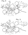
- Fig. 4 shows the relative position taken by the core A and pressers 43 a few moments after severance of the web material N.
- the rotary unit 41 keeps on rotating at a speed lower than the web feeding speed, and also less than the advancing speed of core A1, so that a progressive approach of the core to the pressers 43 will take place. However, contact between core and pressers is avoided since a slight rotation of the rotary unit 41, causes the presser means move out of the channel 39 through the spaces between the strips 35. This allows the core A1 to roll forward up to the nip 19 as shown in Fig. 5.
- the core has left the surface 33 and is in contact with the surfaces of the winder rollers 15 and 17 which, by rotating at slightly different speeds (roller 17 being slower), cause the core to move forward through the nip 19.
- the core will be located between the three rollers 15, 17 and 21, and the web material N will continue to wind up on the core, some turns thereof having already been wound during the transit of the core through the channel 39 and the nip 19.
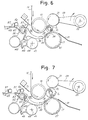
- the unit 41 keeps on rotating in clockwise direction until it reaches the position in Fig. 6 where it stops until the next operating cycle.
- the auxiliary pushing member 67 which has continued to rotate simultaneously with the unit 41, is stopped at the angular position shown in Fig. 6.
- the log L is shown in an intermediate winding step between the rollers 15, 17 and 21, the movable roller 21 being gradually moved upwards to allow the controlled increase of the log.
- the conveyor 47 keeps on moving forward thus bringing the next core A2 to the inlet of channel 39, as can be seen in the next Fig. 7.
- the conveyor 47 may be provided with either continuous or intermittent motion, also in relation to the rewinder speed.
- Fig. 8 shows the almost completed log L, the core A2 being brought by the pusher 57 to the inlet of channel 39 and held in that position by a resilient retention finger 71. The latter prevents the core A2 from rolling down and coming in contact with the web material N before the rotary unit 41 is in place.
- FIG. 8 illustrates the sequence of operations in which the contact between the new core A1 and the web material N takes place an instant before the material N is torn off, and precisely the moment in which the contact between the pressers 43 and the material N begins.
- the contact between the core A1 and the web material N may also be controlled to take place simultaneously with the tear, or with some delay.
- the regions 15A and 15B have annular development, it is possible to have the contact between the roller 15 and the pressers 43 at any point along the periphery of the roller 15. This allows the web material N to be severed at any moment, and thus an amount of web material N (accurately presettable independently of the circumferential development of the roller 5) to be wound on each log.
- severing means of different type may also be used.
- Fig. 10 shows severing means 43 having sharp, saw-toothed blades 43A which cooperate with annular slots 15C provided in the surface of roller 15. The difference in speed between the blades 43A and the surface of the roller 15 causes the web material to tear. Also, in this case, there is no limitation between the angular position of the roller 15 and the position in which the severing means 43 operate.
- Fig. 11 shows, instead, a solution in which the blades 43A cooperate with a longitudinal (i.e., axial) slot 15D formed in the surface of roller 15.
- the slot 15D is of a size which is sufficient to avoid interference between the two elements.
- this embodiment has the advantage of avoiding mutual mechanical contact between the severing means and the winder roller 15.
- a relation does exist between the angular position of the roller 15 and the position of the severing means 43, 43A. This imposes limits to the machine's versatility.
- the length of the web material wound on each log may vary only according to multiples of the circumference of roller 15, unless a mutual sliding between the web material N and the roller 15 is provided during winding of each log, with consequent cyclical rephasing of the position of the slot 15D and severing means 43, 43A.
- Figs. 10 and 11 are particularly suitable in case the rewinder has no perforation group 5. In this case, the rupture of the web material occurs where the serrated and/or sharpened blades are inserted.
- a synchronism must be suitably provided between the action of the severing means 43 and the position of the perforation line, so that the contact between the web material N and the severing means occurs in close proximity to a perforation line with the latter lying immediately downstream of the region of contact.
- a control unit schematically shown at 2 to which data of angular position relative to the position of the cylinder 9 is supplied.
- the control unit 2 operates an actuator 75 which, as described hereinafter, controls the operation for the severance of the web material, as well as the insertion of the new core and the unloading of the log in synchronism with the position of the perforation line.
- the same control unit 2 may control the actuator 27 which moves the roller 21 up and down.
- Fig. 12 schematically shows a particularly advantageous example of the actuator and the drive means which control the motion of the web material severing means and core insertion means and the deceleration of the winder roller 17.
- Fig. 12 is a section taken on the line XII-XII of Fig. 1 from which the parts having no significant relation with the description of the means for the actuation of the rotary unit 41 have been taken away.
- Numeral 75 indicates a motor serving as actuator of the rotary unit 41.
- a first toothed pulley 79 over which a toothed belt 81 is driven, the latter transmitting the motion to the rotary unit 41 via another pulley 83.
- a second toothed pulley 85 keyed on the shaft 77, transmits the motion, via a toothed belt 87, to a toothed pulley 89.
- the pulley 89 is keyed on a first input axle of a differential gear generally shown at 91.
- a pulley 93 Fixed to the gear-holding case or box of the differential gear 91 is a pulley 93 on which a belt 95 is driven, the latter taking its motion from a machine member, not shown, rotating at a speed proportional to the feeding speed of the web material N.
- Said member may be any one of the web material-guiding and feeding rollers, such as the roller 15.
- Numeral 97 designates the output axle of the differential gear 91. Keyed on said output axle is a toothed pulley 99 which, through a toothed belt 101, transmits the motion to a toothed pulley 103 keyed on the shaft of the second winder roller 17.
- Also keyed on the rotary unit 41 is another pulley 105 which, through a belt 107, transmits the motion to a pulley 109 keyed on the shaft 68 which carries the auxiliary pushing member 67.
- the motor 75 In the winding stage of the log L between the rollers 15, 17 and 21 (i.e., in the stage shown in Figs. 6 and 7), the motor 75 is at a standstill.
- the winder roller 17 is rotated directly by belt 95.
- the transmission ratio of the differential gear and of the pulleys is such as to achieve a peripheral speed of the roller 17 equal to the peripheral speed of the roller 15.
- the motor 75 is rotated.
- a single actuator (motor 75) makes it possible to operate the severance of the web material, the insertion of a new core and the discharge of a completed log, by use of an extremely simple and economical mechanism.
- Fig. 13 shows a modified embodiment in which the channel 39 is not formed by the surface of a first winder roller, but by a separate web feeding means consisting of a plurality of belts 150 driven between a first winder roller 15, and an auxiliary cylinder 152, said belts being suitably spaced apart in the axial direction.
- Numeral 33 again indicates the surface defining, together with the belt system 150, a channel 39.
- the second and third winder rollers are again designated 17 and 21, respectively.
- Numeral 41 indicates the rotary unit carrying the severing means 43 which move through the slits between the strips 35 which define the surface 33.
- the core insertion means have been omitted in the drawing for the sake of clarity.
- the surface 154 is a surface which the belts 150 contact.
- the surface 154 may have a plurality of sliding seats for the belts 154, so that the severing means 43 (consisting of pressers or other means, as described above) act on an almost continuous transverse surface.
- the surface 54 may be made of a material having low coefficient of friction to facilitate both the sliding of the belts 152 and the tearing of the web material.
- the belts 152 are located in alignment with the strips 35 which define the surface 33, and the pressers 43 pass between adjacent belts 150.
- the interruption means may comprise blade means which cut the web material, in a similar way as provided by the means 43A.
- the speed of means 43, 43A may also be equal to the speed of the web material N, as the separation thereof is performed by a cutter (means 43A) or a counteracting stationary surface (154).
Landscapes
- Replacement Of Web Rolls (AREA)
- Making Paper Articles (AREA)
- Preliminary Treatment Of Fibers (AREA)
- Winding Of Webs (AREA)
- Advancing Webs (AREA)
- Winding, Rewinding, Material Storage Devices (AREA)
Abstract
Description
- The invention refers to a surface rewinding machine and method for the formation of logs or rolls of web material wound on a central core. Such rewinding machines are well-known, described, for example, in U.S. Patents No. 4,487,377; 4,723,724; 4,327,877 and 4,828,195; U.K. Patent No. 2,105,688; and in EP-A-0 489 039.
- More in particular, the present invention refers to a rewinding machine which includes a first winder roller on which the web material is fed; a second winder roller defining, with the first winder roller, a nip through which the core and the web material pass; means for feeding the web material to said nip; means for introducing a core on which the web material is to be wound; and a web material severing means cooperating with said first winder roller.
- A rewinder of this type is described, for example, in U.S. Patent 4,487,377.
- These rewinders are used for producing smaller-diameter logs or rolls of web material from large-diameter parent rolls. Typically, these machines are used in the paper converting industry to produce rolls of toilet paper, kitchen towels, all-purpose wipers and the like. The formed logs may be as long as 350 cm and only 10-15 cm in outer diameter, and are subsequently cut transversely to their axis to obtain small rolls which may be only 10-30 cm long.
- In the production of such logs, it is important to use reliable machines able to run at high production speeds (in the range of 600-1000 m/minute) which provide a consistently high-quality product, with uniform windings, especially of the first loops. The length of the material on each log must be presetable and maintained, from log-to-log, with great accuracy.
- One way to obtain high production rates and a high quality of the manufactured product is shown in U.S. Patent 4,487,377, which provides for a web-cutting member which cooperates with the first winder roller of the rewinder. The web material is cut upstream of the point where the core is introduced. After cutting, the leading edge of the web material adheres to the surface of the winder roller and is transferred (by the rotation of the latter) towards the winding region where the leading edge is made to adhere to a new core suitably introduced by an insertion means.
- This machine requires means (for holding the leading edge of the web material onto the winder roller) which are housed inside the winder roller and which must be timely activated and deactivated to hold and release the edge at preset moments, thereby allowing the starting of the winding on a new core.
- In US-A-4,327,877 a machine is described, wherein the web is torn between the core and the second winding roller once the core has been introduced into the nip. Tearing is obtained by a suction means inside the second winding roller. Said suction means forms a loop of web material which is pinced between the new core and the second roller.
- A first object of the present invention is a rewinding machine which is able to produce a high-quality finished product at high speeds with a simpler and more economical construction than that of known rewinders. A further object of the present invention is to provide a versatile rewinder able to produce logs of varying length without requiring complex mechanisms for adaptation to different lengths of web material without a slipping of the web material on the winder roller onto which it is fed. Another object of the present invention is the construction of a rewinder having means for tearing or cutting the web material, which means are reliable, simple, and inexpensive to produce and maintain.
- These and further objects and advantages will appear evident to the skilled in the art by the following description.
- In the rewinder according to the present invention, a surface or track is provided upstream of the nip between the winder rollers, which defines, together with the web feeding means which feeds the web material into the nip, a channel into which the core is introduced. A web-severing means cooperates with said web feeding means at an intermediate position along said channel between the region of insertion of the new core and the nip defined between the winder rollers.
- According to the invention, a machine is provided wherein a core is inserted into a channel upstream of the nip between a first and a second winder roller. The web material is severed downstream of the core insertion region by severing means which cooperate with the first winder roller or other means for feeding the material into the nip. This avoids the need of accelerating one of the winder rollers, and the severed web material begins to wind up on the core while the core starts to roll into the channel and on the surface or track by the rotation of the first winder roller. In some cases, the web-feeding means may be a belt system combined with said first winder roller.
- This arrangement allows a precise severance of the web material to be carried out by severing means which cooperate with the first winder roller, without having to hold the leading edge of the web material on the winder roller, inasmuch as at the moment of severance of the web material, the new core is already in contact with the web material. Furthermore, the un-tensioning of the web material upstream of the winding region is substantially eliminated.
- If desired, the start of the winding of the web material around the core may be assisted by placing glue on the surface of said core, or by suitable air jet or vacuum or mechanical means. The use of glue ensures a more reliable operation and increases the quality of the final product.
- The surface or track for the rolling of the core extends, substantially, from the position where the introduction means discharges the core, up to the nip between the two winder rollers. To make the transit of the core from the non-moving surface or track to the second rotating winder roller easier, said surface is preferably comb-shaped, at least in the terminal portion thereof. This comb-like terminal portion cooperates with annular slots in the second winder roller to allow the core, having the first turns of web material wound thereon, to be transferred smoothly and without shocks or strains to the nip between the winder rollers.
- In practice, since the extension of the track surface on which the core rolls (prior to the insertion thereof into the nip) is relatively short, and the web material very thin, any increase in diameter due to the winding of the first turns is insignificant. Accordingly, the track or fixed surface can define, together with the cylindrical surface of the first winder roller, a channel of substantially uniform cross-section and, advantageously, of a height slightly lower than the diameter of the core. The difference between the height of the channel and the diameter of the core causes the latter to be slightly squeezed when initially inserted thereinto, and this advantageously allows the web material to adhere to the core while facilitating the rotational acceleration of said core.
- In practice, the severing means are so constructed as to be able to move along a cylindrical path which is almost tangent to the cylindrical surface of the first winder roller, or slightly interfering therewith. The peripheral speed of the cylindrical surface of the first winder roller and of the web material carried thereon is higher than the tangential speed of the severing means along said path. In this way, when the web material is pinched between the severing means and the cylindrical surface of the first winder roller, the difference in speed causes a slight retardation of the web material and thus the tearing thereof. The rotational speed of the unit which carries the severing means is precisely controlled. Perforation lines on the web material adjacent the severing means will facilitate the tearing of the web material.
- In order for the severing means to enter in contact with the web on the cylindrical surface of the first winder roller at an intermediate position along the said channel, (while the rotary unit carrying the severing means is arranged outside the channel), the severing means pass through slots or apertures in said track. Thus, by controlling the rotational speed of the unit, the severing means moves out of the channel ahead of the core which is passing therethrough. The apertures or slots in the track may be obtained, for example, by providing a plurality of strips parallel to one another in the direction of advancement of the web material. The distance between the strips is sufficient to allow the passage of the severing means.
- In order to increase the versatility of the machine and simplify the construction of the web material severing means, in a preferred embodiment of the rewinder, the severing means are made in the form of pressers or pads (resilient, if required) which press against the surface of the first winder roller, or other material feeding means, to pinch the web material. Advantageously, to make the tearing of the web material easier, in the regions where the pressers act against the roller, the surface of the first winder roller may have a low coefficient of friction. To this end, the first winder roller may be provided with a surface having wide annular bands suitably polished, having a low coefficient of friction, and separated by narrow annular strips having a high coefficient of friction. This ensures the proper friction on the web to properly feed said web, in particular at the moment when the new core is rotationally accelerated. The annular strips with high coefficient of friction may be aligned with the strips which define the track or core rolling surface.
- With the arrangement above described, the length of the material wound into each individual log may be pre-determined and accurately controlled, regardless of the diameter or circumference of the first winder roller, inasmuch as there is no need for coordinating the position of the severing means with a particular portion of the surface of the winder roller, as is the case in the prior art machines.
- Similar results in terms of versatility are attained if the severing means are provided with blade portions (saw-toothed, if required) which cooperate with annular channels in the first winder roller. Blade means could operate with a longitudinal slot instead of annular channels.
- The unloading from the winder of a completed log or roll may take place by an accelerating third, diameter-control, roller disposed downstream of the first and second winder rollers, in a manner similar to that described in the above-mentioned GB-A-2,105,688. However, provision may also be made for the completed log to be unloaded by deceleration of the second winder roller, while keeping the peripheral speed of the third winder roller constant and substantially equal to the peripheral speed of the first winder roller. The deceleration of the second winder roller also causes the core to go through the nip defined by the first and second winder rollers.
- It is not excluded that the core passes through the nip between the first and second winder rollers by means of a small and constant difference in the peripheral speed between said two winder rollers. In this case, it may be necessary to provide a relative mobility of the first and second winder rollers.
- When provision is made for a deceleration of the second winder roller in order to unload the completed log and/or to allow the passage of the core through the nip, an actuator means may be provided which causes both the deceleration of said roller and the actuation of the web material severing means. This is possible because the latter will have to be operated only when a log has been completed and a new core has to be introduced, i.e., when the deceleration of the second winder roller is necessary. This greatly simplifies the structure of the machine.
- With the above and other objects in view, further information and a better understanding of the present invention may be achieved by referring to the following detailed description.
- For the purpose of illustrating the invention, there is shown in the accompanying drawings a form thereof which is at present preferred, although it is to be understood that the various instrumentalities of which the invention consists can be variously arranged and organized, and that the invention is not limited to the precise arrangement and organizations of the instrumentalities as herein shown and described.
- In the drawings, wherein like reference characters indicate like parts:
- Fig. 1 shows a schematic side view of the rewinder according to the invention.
- Figs. 2 to 8 diagrammatically show successive working steps of the rewinder of Fig. 1.
- Fig. 9 shows a section taken on line IX-IX of Fig. 1.
- Figs. 10 and 11 show two embodiments of the web material severing means in a schematic side view.
- Fig. 12 shows a section taken on line XII-XII in Fig. 1 of one side frame on which the winder rollers and the severing means are supported, to illustrate the transmission for the actuation of the web material severing means and the deceleration of the second winder roller.
- Fig. 13 shows a modified embodiment of the invention wherein a belt is additionally combined to the first winder roller.
- The basic elements of the rewinder will be described hereinafter by referring first to Fig. 1.
Reference numerals 1 and 3 indicate rollers around which the web material N is fed from a supply parent roll (not shown) to the winding region of the rewinder. The web material N is fed through a perforation group, generally shown at 5, including anon-rotating support 7 and a rotating cylinder 9. Thesupport 7 carries a counter-blade 11 which cooperates withblades 13 carried by the cylinder 9 to provide a line of perforations across the web. - Located downstream of the
perforation group 5 are afirst winder roller 15, around which the web material is fed, and asecond winder roller 17. In the illustrated example, the tworollers rollers Numeral 21 designates a third roller also rotating in a counter-clockwise direction and supported by anarm 23 pivoted at 25 to the machine frame. Thearm 23 can oscillate to allow theroller 21 to be lifted and lowered by anactuator 27. Thewinder rollers - Located downstream of the three winder rollers is a
chute 31 along which the completed logs L roll for the transfer thereof towards tail gluer means, not shown. - Disposed upstream of the
nip 19 is a curved surface or track 33 defined by a series of parallel arcuate strips 35 (Fig. 9). Thestrips 35 have pointed ends 36 directed toward thenip 19 and which terminate inannular slots 37 of thelower winder roller 17. (See Figs. 10, 11 and 12). At the opposite end, thestrips 35 terminate near the region at which the introduction of the cores A takes place, the latter being fed and inserted in the manner described hereinafter. - The curved surface or
track 33 and the cylindrical surface of thefirst winder roller 15 define achannel 39 for the passage of the cores A. The cross-section, i.e., the dimension of thechannel 39 measured perpendicularly to thetrack 33, may be substantially uniform along the length of the strips and advantageously equal to, or slightly less than the diameter of the cores being used. This is achieved because the surface of thetrack 33 has a constant radius of curvature with its axis coincident with the axis of thewinder roller 15. - Arranged below the
strips 35 which define thesurface 33 is arotary unit 41 carrying means 43, for the severance of the web material, which cooperate with the cylindrical surface of thewinder roller 15. In this embodiment, the severing means includes pressers orpads 43 intended to exert a pressure, through a slight interference, against the surface of theroller 15. Theunit 41 is made to rotate intermittently, in the illustrated example, in a clockwise direction. Thepressers 43 move along a circular path C which has an axis coincident with the axis ofrotation 45 of theunit 41 and almost tangent to (or making a slight interference with) the cylindrical surface of thewinder roller 15. - The cores are introduced into the
channel 39 by means of a conveyor generally shown at 47 (see Fig. 1). The conveyor includes a flexiblecontinuous member 49 made up, for example, of a chain or a belt driven aroundtransmission wheels flexible member 49 arepushers 57 each of which picks up a core from acontainer 59. The cores A are removed by thepushers 57 and lifted and transferred, through a gluing unit, generally shown at 61, which may include atank 63 of glue in which a series ofdiscs 65 rotate. Such gluers are well-known and need not be described in greater detail. - In Fig. 1 only a few cores A are shown, but it is to be understood that, under proper operating conditions, a respective core A is carried by each
pusher 57 from thecontainer 59, across thewheel 51 to thewheel 55, close to the mouth of thechannel 39, to start the winding of each log, as will be described hereinafter with reference to Figs. 2 to 8. - Fig. 2 shows the final step of the winding of a log L. The
first winder roller 15 and thethird roller 21 rotate at a peripheral speed equal to the web material N feeding speed, while thesecond winder roller 17 rotates at a temporary lower peripheral speed to allow the completed log L to be moved towards thechute 31. At this stage, a new core A1 has been brought by therelevant pusher 57 to the entrance ofchannel 39. The insertion of the core A1 into thechannel 39 may be carried out directly by therelevant pusher 57, or by an auxiliary pushing member, indicated by 67, rotating about the axis ofwheel 55. The latter solution (shown in the illustrated example) allows the insertion of the core A to be performed with greater rapidity and precision, inasmuch as the insertion movement is unrelated to the movement ofconveyor 47, thepush member 67 being provided with an actuator which is independent of the actuator of theconveyor 47. - During this stage, the
rotary unit 41 rotates about itsaxis 45 and thepressers 43 have already entered thechannel 39 by passing between thestrips 35 which define thesurface 33. The peripheral speed ofpressers 43 is less than that ofroller 15 and, therefore, also less than the speed of the web material N. In this way, the web material N is pressed between the two surfaces moving at different speeds. The effect of this difference in speed is a slowing down of the pinched portion with respect to the rest of the web material. This slowing down causes the web material to tear along the perforation line which is closest to the point at which the web material N is pinched. - Fig. 3 shows the next stage in which the web material is torn off, giving rise to a new leading edge NL. The core A1 has, in the meantime, started to rotate owing to the contact thereof with the
stationary surface 33 and with the rotating cylindrical surface of thewinder roller 15. The core moves forward (i.e., downstream), therefore, by rolling alongsurface 33 at a speed equal to half the feeding speed of the web material N. The cross dimension ofchannel 39, which is slightly less than the diameter of the core A1 (the latter being typically made from pliable cardboard), allows a friction to be generated. This friction is necessary for the angular acceleration of the core from zero to the rolling speed, and the adhesion of the web material N to the surface of said core, on which glue has been spread by the gluingdevice 61. The latter effect is missing when the gluing of the core is not provided. - Fig. 4 shows the relative position taken by the core A and pressers 43 a few moments after severance of the web material N. The
rotary unit 41 keeps on rotating at a speed lower than the web feeding speed, and also less than the advancing speed of core A1, so that a progressive approach of the core to thepressers 43 will take place. However, contact between core and pressers is avoided since a slight rotation of therotary unit 41, causes the presser means move out of thechannel 39 through the spaces between thestrips 35. This allows the core A1 to roll forward up to the nip 19 as shown in Fig. 5. - In Fig. 5, the core has left the
surface 33 and is in contact with the surfaces of thewinder rollers roller 17 being slower), cause the core to move forward through thenip 19. At the end of its advancement through thenip 19, the core will be located between the threerollers channel 39 and thenip 19. - At this time the
unit 41 keeps on rotating in clockwise direction until it reaches the position in Fig. 6 where it stops until the next operating cycle. Similarly, theauxiliary pushing member 67, which has continued to rotate simultaneously with theunit 41, is stopped at the angular position shown in Fig. 6. - In this figure, the log L is shown in an intermediate winding step between the
rollers movable roller 21 being gradually moved upwards to allow the controlled increase of the log. Conversely, theconveyor 47 keeps on moving forward thus bringing the next core A2 to the inlet ofchannel 39, as can be seen in the next Fig. 7. Theconveyor 47 may be provided with either continuous or intermittent motion, also in relation to the rewinder speed. - In case the auxiliary pushing
member 67 is not provided, the motion of theconveyor 47 should be in phase with that of thepressers 43 and the relevant rotatingunit 41. - Fig. 8 shows the almost completed log L, the core A2 being brought by the
pusher 57 to the inlet ofchannel 39 and held in that position by aresilient retention finger 71. The latter prevents the core A2 from rolling down and coming in contact with the web material N before therotary unit 41 is in place. - As the
rotary unit 41 and the auxiliary pushingmember 67 are advanced, the system takes up the configuration shown in Fig. 8. As can be seen in this Figure, theauxiliary pushing member 67 is about to push the core A2 into the inlet ofchannel 39, and thus in contact with the web material N, and thepressers 43 are about to come in contact with the surface of thefirst winder roller 15. The next position is a repeat of the cycle as shown in Fig. 2.Figs. 2 to 8 illustrate the sequence of operations in which the contact between the new core A1 and the web material N takes place an instant before the material N is torn off, and precisely the moment in which the contact between thepressers 43 and the material N begins. - However, the contact between the core A1 and the web material N may also be controlled to take place simultaneously with the tear, or with some delay.
- Tearing of the web material by
pressers 43 is made easier by the fact that these are provided with a surface with high coefficient of friction, for example, made of rubber, while the corresponding regions of theroller 15 have a low coefficient of friction which facilitates the sliding of the web material on said roller. This arrangement may be as shown, in detail, in Fig. 9. In theannular regions 15A in which the contact ofpressers 43 takes place, theroller 15 has a smooth surface.Said regions 15A are separated from one another byannular strips 15B having high coefficient of friction, disposed in alignment with thestrips 35 and made up, for example, of emery cloth. This material is often employed on rollers to prevent the slipping of the web material. - In this embodiment, since the
regions roller 15 and thepressers 43 at any point along the periphery of theroller 15. This allows the web material N to be severed at any moment, and thus an amount of web material N (accurately presettable independently of the circumferential development of the roller 5) to be wound on each log. - Instead of presser means, such as those indicated by 43 in Figs. 1 to 8, severing means of different type may also be used. For example, Fig. 10 shows severing means 43 having sharp, saw-
toothed blades 43A which cooperate with annular slots 15C provided in the surface ofroller 15. The difference in speed between theblades 43A and the surface of theroller 15 causes the web material to tear. Also, in this case, there is no limitation between the angular position of theroller 15 and the position in which the severing means 43 operate. - Fig. 11 shows, instead, a solution in which the
blades 43A cooperate with a longitudinal (i.e., axial)slot 15D formed in the surface ofroller 15. According to the difference in speed between themeans 43 and the roller surface, theslot 15D is of a size which is sufficient to avoid interference between the two elements. Similarly to the embodiment of Fig. 10, this embodiment has the advantage of avoiding mutual mechanical contact between the severing means and thewinder roller 15. However, in the embodiment of Fig. 10, a relation does exist between the angular position of theroller 15 and the position of the severing means 43, 43A. This imposes limits to the machine's versatility. In fact, the length of the web material wound on each log may vary only according to multiples of the circumference ofroller 15, unless a mutual sliding between the web material N and theroller 15 is provided during winding of each log, with consequent cyclical rephasing of the position of theslot 15D and severing means 43, 43A. - The embodiments of Figs. 10 and 11 are particularly suitable in case the rewinder has no
perforation group 5. In this case, the rupture of the web material occurs where the serrated and/or sharpened blades are inserted. - In the embodiments of Figs. 10 and 11, it is possible to operate the severing means at a peripheral speed equal to that of the web material, thereby reducing the width of
channel 15D. In this case, the severance of the web material N is due to the incision thereof and not to a difference in speed. - In case the web material is perforated (as by unit 5), a synchronism must be suitably provided between the action of the severing means 43 and the position of the perforation line, so that the contact between the web material N and the severing means occurs in close proximity to a perforation line with the latter lying immediately downstream of the region of contact. To this end, provision may be made for a control unit, schematically shown at 2, to which data of angular position relative to the position of the cylinder 9 is supplied. The
control unit 2 operates anactuator 75 which, as described hereinafter, controls the operation for the severance of the web material, as well as the insertion of the new core and the unloading of the log in synchronism with the position of the perforation line. Thesame control unit 2 may control theactuator 27 which moves theroller 21 up and down. - Fig. 12 schematically shows a particularly advantageous example of the actuator and the drive means which control the motion of the web material severing means and core insertion means and the deceleration of the
winder roller 17. - In Fig. 12, numeral 73 indicates one of the machine's side frame which supports the
second winder roller 17, therotary unit 41, and thecylinder 68 which supports the auxiliary pushingmember 67. Fig. 12 is a section taken on the line XII-XII of Fig. 1 from which the parts having no significant relation with the description of the means for the actuation of therotary unit 41 have been taken away. -
Numeral 75 indicates a motor serving as actuator of therotary unit 41. Keyed on theshaft 77 ofmotor 75 is a firsttoothed pulley 79 over which atoothed belt 81 is driven, the latter transmitting the motion to therotary unit 41 via anotherpulley 83. A secondtoothed pulley 85, keyed on theshaft 77, transmits the motion, via atoothed belt 87, to atoothed pulley 89. Thepulley 89 is keyed on a first input axle of a differential gear generally shown at 91. Fixed to the gear-holding case or box of thedifferential gear 91 is apulley 93 on which abelt 95 is driven, the latter taking its motion from a machine member, not shown, rotating at a speed proportional to the feeding speed of the web material N. Said member may be any one of the web material-guiding and feeding rollers, such as theroller 15.Numeral 97 designates the output axle of thedifferential gear 91. Keyed on said output axle is atoothed pulley 99 which, through atoothed belt 101, transmits the motion to atoothed pulley 103 keyed on the shaft of thesecond winder roller 17. - Also keyed on the
rotary unit 41 is anotherpulley 105 which, through abelt 107, transmits the motion to apulley 109 keyed on theshaft 68 which carries theauxiliary pushing member 67. In the winding stage of the log L between therollers motor 75 is at a standstill. Thewinder roller 17 is rotated directly bybelt 95. The transmission ratio of the differential gear and of the pulleys is such as to achieve a peripheral speed of theroller 17 equal to the peripheral speed of theroller 15. When the winding of the log L is almost completed, themotor 75 is rotated. This has the effects of: (a) driving therotary unit 41 which carries the severing means 43 into rotation; (b) driving theshaft 68 which supports the auxiliary pushingmember 67 into rotation; and (c) modifying the transmission ratio between thepulley 93 and thewinder roller 17 as a consequence of the rotation of the input axle of the differential 91. The modification of the transmission ratio between thepulley 93 and theroller 17 causes a deceleration of the latter and, therefore, a reduction of its peripheral speed with respect to the peripheral speed ofroller 15. This deceleration is sufficient to unload the just-completed log L. - Consequently, a single actuator (motor 75) makes it possible to operate the severance of the web material, the insertion of a new core and the discharge of a completed log, by use of an extremely simple and economical mechanism.
- However, different and independent actuators for the various members can be used. Provision may also be made for using a
winder roller 17 rotating uniformly at a speed lower than that ofroller 15 and for operating the discharge of the completed log L by accelerating theroller 21. This does not change the principle of the invention. When providing an acceleration of theroller 21, this may also have the effect of tensioning the web material N. By suitably phasing, for example, through thecontrol unit 2, the acceleration ofroller 21 with the actuation of the severing means 43, it is possible to pre-tension the web material before causing the tearing thereof by the contact between themeans 43 and theroller 15. - Fig. 13 shows a modified embodiment in which the
channel 39 is not formed by the surface of a first winder roller, but by a separate web feeding means consisting of a plurality ofbelts 150 driven between afirst winder roller 15, and anauxiliary cylinder 152, said belts being suitably spaced apart in the axial direction.Numeral 33 again indicates the surface defining, together with thebelt system 150, achannel 39. The second and third winder rollers are again designated 17 and 21, respectively.Numeral 41 indicates the rotary unit carrying the severing means 43 which move through the slits between thestrips 35 which define thesurface 33. The core insertion means have been omitted in the drawing for the sake of clarity. - Indicated by 154 is a surface which the
belts 150 contact. Thesurface 154 may have a plurality of sliding seats for thebelts 154, so that the severing means 43 (consisting of pressers or other means, as described above) act on an almost continuous transverse surface. The surface 54 may be made of a material having low coefficient of friction to facilitate both the sliding of thebelts 152 and the tearing of the web material. - The
belts 152 are located in alignment with thestrips 35 which define thesurface 33, and thepressers 43 pass betweenadjacent belts 150. - Also in this embodiment the interruption means may comprise blade means which cut the web material, in a similar way as provided by the
means 43A. The speed ofmeans - It is understood that the drawings show an exemplification given only as a practical demonstration of the invention, as this may vary in the forms and dispositions without, nevertheless, coming out from the scope of the idea on which said invention is based. The possible presence of reference numbers in the appended claims has the purpose of facilitating the reading of the claims, reference being made to the description and the drawing, and does not limit the scope of the protection represented by the claims.
Claims (36)
- A rewinding machine for the formation of logs (L) of web material (N) wound on a core (A), including:- a first winder roller (15) over which the web material is fed;- a second winder roller (17) defining, with the first winder roller, a nip (19) through which the core (A) and the web material (N) pass;- means (15; 150) for feeding the web material (N) into said nip (19), which have an advancement speed substantially equal to the feeding speed of the web material (N);- insertion means (47; 57; 67) for introducing into said nip a core on which the web material is to be wound;- a web severing means (43; 43A) cooperating with said feeding means;
characterized in that:- located upstream of said nip (19), with respect to the web (N) feeding direction, is a surface (33) defining, together with the means (15; 150) for the feeding of the web material (N), a channel (39) into which the core (A) is inserted, the core in said channel being in contact with both said surface (33) and the web material fed by said feeding means, the motion of the feeding means (15; 150) causing the core to advance along said channel (39);- said means (43; 43A) for severing the web material cooperates with said feeding means (15; 150) at an intermediate location along said channel, whereby said web is severed between the region of insertion of the new core and said nip (19). - A rewinding machine according to Claim 1, characterized in that said means for feeding the web material (N) into the nip (19) consists of the cylindrical surface of the first winder roller (15), and furthermore said surface (33) defining said channel (39) is a curved surface.
- A rewinding machine according to Claim 1, characterized in that said means for feeding the web material (N) into the nip (19) includes a conveyor system with flexible members (150) driven around the first winder roller (15).
- A rewinding machine according to Claim 2, characterized in that said surface (33) defining said channel (39) is a concave surface with a center of curvature coinciding with the center of rotation of the first winder roller (15), the height of said channel (39) being equal to or slightly less than the diameter of the core.
- A rewinding machine according to Claim 3, characterized in that associated to said flexible members (150) is a counteracting surface (154).
- A rewinding machine according to one or more of the preceding claims, characterized in that said surface (33) begins adjacent the point where the insertion means (67) releases the core and terminates near said nip (19).
- A rewinding machine according to one or more of the preceding claims, characterized in that: said severing means (43; 43A) move along a path (C) which is approximately tangent to said means for feeding the web material into the nip; and that, during the cooperation between the severing means and the feeding means, the feeding speed of the web material and that of the feeding means (15; 150) is greater than the peripheral speed of the severing means, the difference in speed creating a tensioning and thus a tearing of the web material between the formed log (L) and the region of contact between the web material and the severing means.
- A rewinding machine according to one or more of claims 1 to 6, characterized in that: said severing means (43; 43A) move along a path (C) which is approximately tangent to the means for feeding the web material into the nip; that, during the cooperation between the severing means and the feeding means, the feeding speed of the web material (N) is approximately equal to the peripheral speed of the severing means, said severing means carrying blade members for the severance of the web material.
- A rewinding machine according to one or more of the preceding claims, characterized in that said surface (33) defines with said feeding means (15; 150) a channel of almost uniform cross-section.
- A rewinding machine according to one or more of the preceding claims, characterized in that said surface (33) has a terminal comb-like portion (36) with teeth which terminate in annular slots (37) in the surface of the second winder roller (17).
- A rewinding machine according to one or more of the preceding claims, characterized in that said surface (33) is defined by a plurality of strips (35) approximately parallel to one another extending in the web material feeding direction.
- A rewinding machine according to Claim 11, characterized in that the first winder roller has, on its cylindrical surface, annular regions (158) with high coefficient of friction, disposed in alignment with the parallel strips (35) defining said surface (33).
- A rewinding machine according to one or more of the preceding claims, characterized in that said severing means (43; 43A) are borne by a rotary unit (41) disposed outside said channel (39) defined by said surface (33), said severing means entering said channel through apertures in said surface (33).
- A rewinding machine according to one or more of the receding claims, characterized in that said severing means (43) include presser members (43) cooperating with the web feeding means.
- A rewinding machine according to Claim 14, characterized in that said presser members (43) are resilient.
- A rewinding machine according to Claim 14 or 15, characterized in that the surface of said presser members wich cooperates with said feeding means has high coefficient of friction.
- A rewinding machine according to Claim 9, characterized in that said presser members (43) cooperate with surface portions of said feeding means (15; 150) having low coefficient of friction.
- A rewinding machine according to one or more of claims 1 to 13, characterized in that said severing means are provided with blade elements (43A) cooperating with corresponding channels (15C; 15D) in the web feeding means (15; 150).
- A rewinding machine according to Claim 18, characterized in that said channels are annular channels (15C).
- A rewinding machine according to Claim 18, characterized in that said channels are longitudinal channels (15D) extending substantially parallel to the axis of the first winder roller (15).
- A rewinding machine according to one or more of the preceding claims, characterized by means (75, 91) for controlling the speed of the second winder roller, which keep the peripheral speed of the second winder roller (17) at a value less than the peripheral speed of the first winder roller (15) at least during the transit of the core through said nip (19).
- A rewinding machine according to Claim 21, characterized in that said speed control means (75, 91) cause a temporary deceleration of the second winder roller (17) to allow the transit of the core through said nip.
- A rewinding machine according to Claim 22, characterized in that it includes an actuator means (75) for operating the severing means (43), which causes, simultaneously with the operation of the severing means, a temporary deceleration of the second winder roller.
- A rewinding machine according to Claim 23, characterized in that associated with the second winder roller (17) is an epicyclic gear (91) provided with two inputs and one output, said output driving the second winder roller (17) into rotation, a first input (93) being connected to a transmission means (95) which has a motion proportional to the feeding speed of the web material (N), and a second input (89) being connected to the actuator means (75) which operates the severing means (43; 43A).
- A rewinding machine according to one or more of the preceding claims, characterized in that it includes gluing means (61) which apply glue to the core prior to the insertion of the core into said channel (39).
- A rewinding machine according to Claim 25 characterized in that said gluing means are disposed along the path of the core (A) insertion means (47, 57, 67).
- A rewinding machine according to one or more of the preceding claims, characterized in that said insertion means (47, 57, 67) include a container (59) and a conveyor (47) with a flexible continuous member (49), carrying a plurality of pushers (57) which pick up the cores from said container (59) and convey them to the channel (39), said flexible member (49) being curved as it passes the channel inlet.
- A rewinding machine according to Claim 27, characterized in that each core (A) is inserted into the channel (39) directly by the respective pusher member (57).
- A rewinding machine according to Claim 27, characterized in that associated to the flexible member is a retention finger (71) which retains the core prior to the insertion thereof into the channel (39).
- A rewinding machine according to Claim 27 or 29, characterized in that the insertion means further include an auxiliary pushing member (67), moving at a speed independent of the pushers (57) to allow for a fast insertion of the core (A) into said channel (39).
- A rewinding machine according to one or more of the preceding claims, including a third winder roller (21) which is brought into contact with the outer surface of the log (L) in the course of formation and is gradually lifted to allow and control the increase of the diameter of said log (L).
- A rewinding machine according to Claim 31, characterized in that said third winder roller (21) rotates at a peripheral speed substantially equal to the peripheral speed of the first winder roller.
- A rewinding machine according to Claim 31, characterized in that speed control means are provided in order to accelerate said third winder roller (21) to unload the log (L) upon completion thereof.
- A rewinding machine according to one or more of the preceding claims, characterized in that said surface (33) is substantially equi-distant from said feeding means (15; 150) along the entire length of the channel.
- A method of producing logs (L) of web material (N) wound on a core (A) including the steps of:- providing a first winder roller and a second winder roller defining a nip between them for the transit of the web material and the core;- providing means for feeding the web material into said nip;- providing a web severing means cooperating with said means for feeding the web material into said nip;- feeding said web material (N) around said first winder roller;- providing a first core (A) and winding a predetermined amount of web material on said first core to form a log (L);- after having wound said predetermined amount of material on the first core (A), severing the web material to form a leading edge and introducing a second core (A1), the leading edge (NL) of the web material (N) formed after the severance being wound on said second core (A1);- causing the second core (A1) to move through said nip and thereafter completing the winding of a new log on said second core;
characterized by:- providing a surface, upstream of said nip, which defines a channel in cooperation with the means for feeding the web material into said nip;- introducing said second core (A1) into said channel before severing the web material (N) and bringing said second core into contact with the web material (N) carried by said feeding means and with said surface;- rolling said second core along said surface through said channel by said means for feeding the web material;- severing the web material by providing severing means between the region in which the second core contacts the web material and said nip;- starting the winding of the web material along said channel; and- causing said second core (A1) to move through said nip. - Method according to Claim 35, characterized by applying glue on said second core and making the leading edge of web material to adhere to said core by means of said glue.
Applications Claiming Priority (3)
| Application Number | Priority Date | Filing Date | Title |
|---|---|---|---|
| ITFI930058A IT1262046B (en) | 1993-03-24 | 1993-03-24 | REWINDING MACHINE FOR THE FORMATION OF ROLLS OF TAPE MATERIAL WITH MEANS FOR THE INTERRUPTION OF THE TAPE MATERIAL AND RELATIVE WINDING METHOD. |
| ITFI930058 | 1993-03-24 | ||
| PCT/IT1994/000031 WO1994021545A1 (en) | 1993-03-24 | 1994-03-23 | Rewinding machine and method for the formation of logs of web material with means for severing the web material |
Publications (2)
| Publication Number | Publication Date |
|---|---|
| EP0694020A1 EP0694020A1 (en) | 1996-01-31 |
| EP0694020B1 true EP0694020B1 (en) | 1997-07-09 |
Family
ID=11350388
Family Applications (1)
| Application Number | Title | Priority Date | Filing Date |
|---|---|---|---|
| EP94912672A Expired - Lifetime EP0694020B1 (en) | 1993-03-24 | 1994-03-23 | Rewinding machine and method for the formation of logs of web material with means for severing the web material |
Country Status (19)
| Country | Link |
|---|---|
| US (1) | US5979818A (en) |
| EP (1) | EP0694020B1 (en) |
| JP (1) | JP2948908B2 (en) |
| KR (1) | KR100202226B1 (en) |
| CN (1) | CN1041702C (en) |
| AR (1) | AR248258A1 (en) |
| AT (1) | ATE155111T1 (en) |
| AU (1) | AU6512594A (en) |
| BR (1) | BR9406100A (en) |
| CA (1) | CA2158751C (en) |
| DE (1) | DE69404142T2 (en) |
| ES (1) | ES2105683T3 (en) |
| FI (1) | FI116973B (en) |
| GR (1) | GR3024079T3 (en) |
| IL (1) | IL108955A (en) |
| IT (1) | IT1262046B (en) |
| PL (1) | PL174020B1 (en) |
| RU (1) | RU2118936C1 (en) |
| WO (1) | WO1994021545A1 (en) |
Cited By (5)
| Publication number | Priority date | Publication date | Assignee | Title |
|---|---|---|---|---|
| US6056229A (en) * | 1998-12-03 | 2000-05-02 | Paper Converting Machine Co. | Surface winder with pinch cutoff |
| US6079661A (en) * | 1998-12-18 | 2000-06-27 | Paper Converting Machine Co. | Automatic splicer for unwinder |
| US7360738B2 (en) | 2002-07-08 | 2008-04-22 | Fabio Perini | Method for producing variously sized paper logs |
| US9856103B2 (en) | 2013-09-23 | 2018-01-02 | Futura S.P.A. | Device and method for controlling the separation of sheets of paper webs in rewinding machines and a rewinding machine provided with such a device |
| IT201900023415A1 (en) | 2019-12-11 | 2021-06-11 | Mura Emilia Rosa Lucia La | A MULTI-LAYER PRODUCT IN TISSUE PAPER OR SIMILAR, MACHINE AND LINE FOR THE MANUFACTURING OF THIS PRODUCT AND RELATED PRODUCTION METHOD |
Families Citing this family (104)
| Publication number | Priority date | Publication date | Assignee | Title |
|---|---|---|---|---|
| US6648266B1 (en) * | 1993-03-24 | 2003-11-18 | Fabio Perini S.P.A. | Rewinding machine and method for the formation of logs of web material with means for severing the web material |
| US5421536A (en) * | 1993-07-19 | 1995-06-06 | Paper Coverting Machine Company | Surface winder with recycled mandrels and method |
| IT1278644B1 (en) * | 1995-04-14 | 1997-11-27 | Perini Fabio Spa | REWINDING MACHINE FOR ROLLS OF TAPE MATERIAL, WITH CONTROL OF THE INTRODUCTION OF THE WINDING CORE |
| US5725176A (en) | 1996-01-19 | 1998-03-10 | Paper Converting Machine Co. | Method and apparatus for convolute winding |
| IT1286563B1 (en) * | 1996-03-05 | 1998-07-15 | Perini Fabio Spa | REWINDING MACHINE INCORPORATING A GLUER FOR THE COMPLETED ROLLS AND RELATIVE WINDING METHOD |
| US5820064A (en) * | 1997-03-11 | 1998-10-13 | C.G. Bretting Manufacturing Company, Inc. | Winding control finger surface rewinder with core insert finger |
| US6000657A (en) * | 1996-09-18 | 1999-12-14 | C.G. Bretting Manufacturing Company, Inc. | Winding control finger surface rewinder with core insert finger |
| US5772149A (en) * | 1996-09-18 | 1998-06-30 | C. G. Bretting Manufacturing Company, Inc. | Winding control finger surface rewinder |
| IT1289169B1 (en) * | 1997-01-10 | 1998-09-29 | Italconverting Srl | MACHINE AND METHOD FOR THE PRODUCTION OF ROLLS OR LOGS OF SHEET MATERIALS |
| ITFI980034A1 (en) | 1998-02-18 | 1999-08-18 | Perini Fabio Spa | PERIPHERAL REWINDING MACHINE FOR THE PRODUCTION OF ROLLS OF WRAPPED ROLLS AND RELATIVE WINDING METHOD |
| EP1016608B1 (en) * | 1998-12-31 | 2003-11-05 | M T C - Macchine Trasformazione Carta S.r.l. | Rewinding method and machine for making logs of paper web and the like |
| US6308909B1 (en) * | 1999-02-09 | 2001-10-30 | The Procter & Gamble Company | Web rewinder chop-off and transfer assembly |
| IT1307874B1 (en) | 1999-05-11 | 2001-11-19 | Perini Fabio Spa | METHOD AND DEVICE FOR THE PRODUCTION OF ROLLS OF STRUCTURAL MATERIALS WITHOUT A WRAPPING CORE. |
| US6372064B1 (en) * | 1999-12-13 | 2002-04-16 | C. G. Bretting Manufacturing Company, Inc. | Tail sealer apparatus and method |
| IT1314581B1 (en) * | 2000-03-03 | 2002-12-20 | Perini Fabio Spa | COMPACT REWINDER FOR THE PRODUCTION OF ROLLS OF WRAPPED MATERIALS AND RELATED METHOD |
| IT1314596B1 (en) | 2000-03-28 | 2002-12-20 | Perini Fabio Spa | REWINDING MACHINE AND METHOD OF WINDING OF DIMATERIAL ROLLS TAPE ON REMOVABLE SPINDLES |
| US6659387B2 (en) | 2000-11-07 | 2003-12-09 | Paper Converting Machine Co. | Peripheral rewinding machine and method for producing logs of web material |
| US6532851B2 (en) | 2000-12-21 | 2003-03-18 | Paper Converting Machine Company | Apparatus for supporting product during cutting |
| US20020117030A1 (en) * | 2000-12-22 | 2002-08-29 | Gambaro Anthony M. | Multi-blade log saw |
| IT249984Y1 (en) | 2000-12-27 | 2003-07-07 | Gambini Giovanni | REWINDING DEVICE TO FORM A PAPER ROLL IN A REWINDER MACHINE |
| ES2265407T3 (en) * | 2001-02-16 | 2007-02-16 | M T C - Macchine Trasformazione Carta S.R.L. | NUCLEUS FEEDING METHOD IN A REWINDING MACHINE TO PRODUCE ROLLS FROM SHEET MATERIAL. |
| ITMI20010764A1 (en) * | 2001-04-10 | 2002-10-10 | Gambini Giovanna | APPARATUS TO APPLY GLUE TO A SOUL TO BE INSERTED IN A REWINDER TO WIND LOG |
| ITMI20010306U1 (en) † | 2001-06-01 | 2002-12-02 | Gambini Giovanni | DEVICE FOR REWINDING AND FORMING A CARTAIN ROLL A REWINDING MACHINE |
| ITFI20010120A1 (en) | 2001-06-29 | 2002-12-29 | Perini Fabio Spa | DEVICE FOR THE CONTROL OF THE UNLOADING OF THE ROLLS FROM A REWINDER AND REWINDER INCLUDING THIS DEVICE |
| US6729572B2 (en) | 2001-10-31 | 2004-05-04 | Kimberly-Clark Worldwide, Inc. | Mandrelless center/surface rewinder and winder |
| US8757533B2 (en) * | 2002-02-28 | 2014-06-24 | Kimberly-Clark Worldwide, Inc. | Center/surface rewinder and winder |
| US8210462B2 (en) * | 2002-02-28 | 2012-07-03 | Kimberly-Clark Worldwide, Inc. | Center/surface rewinder and winder |
| US7909282B2 (en) * | 2002-02-28 | 2011-03-22 | Kimberly-Clark Worldwide, Inc. | Center/surface rewinder and winder |
| US8042761B2 (en) * | 2002-02-28 | 2011-10-25 | Kimberly-Clark Worldwide, Inc. | Center/surface rewinder and winder |
| US6715709B2 (en) | 2002-04-30 | 2004-04-06 | Kimberly-Clark Worldwide, Inc. | Apparatus and method for producing logs of sheet material |
| ITFI20020122A1 (en) | 2002-07-09 | 2004-01-09 | Perini Fabio Spa | REWINDING MACHINE FOR THE PRODUCTION OF ROLLS OF WRAPPED WIRE AND RELATED METHOD |
| US7175127B2 (en) * | 2002-09-27 | 2007-02-13 | C.G. Bretting Manufacturing Company, Inc. | Rewinder apparatus and method |
| US6877689B2 (en) * | 2002-09-27 | 2005-04-12 | C.G. Bretting Mfg. Co., Inc. | Rewinder apparatus and method |
| ITFI20020194A1 (en) | 2002-10-16 | 2004-04-17 | Perini Fabio Spa | METHOD FOR THE PRODUCTION OF ROLLS OF TAPE MATERIAL AND REWINDER MACHINE THAT IMPLEMENTS THAT METHOD |
| ITFI20020219A1 (en) * | 2002-11-08 | 2004-05-09 | Perini Fabio | PULMETARY WAREHOUSE FOR TUBES, ESPECIALLY CARDBOARD TUBES FOR |
| US7238236B2 (en) * | 2002-11-14 | 2007-07-03 | Kimberly-Clark Worldwide, Inc. | Apparatus for increasing tail adhesion of wet rolls |
| ITFI20020227A1 (en) * | 2002-11-20 | 2004-05-21 | Perini Fabio Spa | REWINDER MACHINE WITH A GLUING DEVICE FOR GLUING THE FINAL FLAP OF THE ROLL FORMED AND RELATED WINDING METHOD |
| JP4580765B2 (en) | 2002-12-03 | 2010-11-17 | フアビオ・ペリニ・ソシエタ・ペル・アチオーニ | Improved winder for roll production of web materials |
| ITFI20030118A1 (en) * | 2003-04-28 | 2004-10-29 | Fabio Perini | DEVICE AND METHOD TO CAUSE THE TAPPING OF PAPER TAPES IN REWINDING MACHINES |
| US7441681B2 (en) * | 2003-08-29 | 2008-10-28 | The Procter & Gamble Company | Apparatus for separating a web material |
| ITFI20030311A1 (en) * | 2003-12-05 | 2005-06-06 | Perini Fabio Spa | REWINDING MACHINE, METHOD FOR THE PRODUCTION OF |
| ITFI20030312A1 (en) * | 2003-12-05 | 2005-06-06 | Perini Fabio Spa | METHOD AND MACHINE FOR THE PRODUCTION OF ROLLS OF RIBBED MATERIAL. |
| ES2300865T3 (en) * | 2003-12-05 | 2008-06-16 | Fabio Perini S.P.A. | PROCEDURE AND MACHINE FOR THE PRODUCTION OF ROLLS OF MATERIAL IN BAND. |
| ITFI20040028A1 (en) | 2004-02-09 | 2004-05-09 | Perini Fabio Spa | METHOD AND DEVICE TO PRODUCE ROLLS OF WRAPPED TAPE MATERIAL |
| DE102004008830A1 (en) * | 2004-02-20 | 2005-09-15 | Böwe Systec AG | Device and method for mechanically closing envelopes |
| ITFI20040061A1 (en) * | 2004-03-18 | 2004-06-18 | Perini Fabio Spa | PERIPHERAL AND CENTRAL COMBINED REWINDING MACHINE |
| US7222813B2 (en) * | 2005-03-16 | 2007-05-29 | Chan Li Machinery Co., Ltd. | Multiprocessing apparatus for forming logs of web material and log manufacture process |
| ITFI20050088A1 (en) * | 2005-05-02 | 2006-11-03 | Perini Fabio Spa | MACHINE AND METHOD FOR THE PRODUCTION OF ROLLS OF MATTRESS MATCHING TOGETHER WITH A SOIL OF WRAPPING AND ROLLING SO IT HAS OBTAINED |
| ITFI20050108A1 (en) * | 2005-05-23 | 2006-11-24 | Perini Fabio Spa | REWINDING MACHINE AND METHOD FOR THE PRODUCTION OF ROLLS OF RIBBED MATERIAL |
| US7472861B2 (en) * | 2005-06-20 | 2009-01-06 | The Procter & Gamble Company | Method for a surface rewind system |
| US7392961B2 (en) * | 2005-08-31 | 2008-07-01 | The Procter & Gamble Company | Hybrid winder |
| US7455260B2 (en) * | 2005-08-31 | 2008-11-25 | The Procter & Gamble Company | Process for winding a web material |
| US20070075176A1 (en) * | 2005-10-05 | 2007-04-05 | Koch Cellulose, Llc | Article, apparatus and method for attachment of a roll of web material to a treated core |
| US8800908B2 (en) * | 2005-11-04 | 2014-08-12 | The Procter & Gamble Company | Rewind system |
| US7546970B2 (en) * | 2005-11-04 | 2009-06-16 | The Procter & Gamble Company | Process for winding a web material |
| ITFI20060014A1 (en) * | 2006-01-18 | 2007-07-19 | Perini Fabio Spa | REWINDING MACHINE AND WINDING METHOD FOR THE PRODUCTION OF ROLLS |
| US7559503B2 (en) * | 2006-03-17 | 2009-07-14 | The Procter & Gamble Company | Apparatus for rewinding web materials |
| US8459586B2 (en) * | 2006-03-17 | 2013-06-11 | The Procter & Gamble Company | Process for rewinding a web material |
| ITFI20060140A1 (en) * | 2006-06-09 | 2007-12-10 | Perini Fabio Spa | METHOD AND PE DEVICE PRODUCING ROLLS OF MATTRESS MATCHING WITH A MECHANISM OF INTERRUPTION OF THE RIBBED MATERIAL OPERATED BY THE TRANSIT OF THE WRAPPING ANIMALS. |
| WO2007141818A2 (en) * | 2006-06-09 | 2007-12-13 | Fabio Perini S.P.A. | Method and machine for forming logs of web material, with a mechanical device for forming the initial turn of the logs |
| CN101088895B (en) * | 2006-06-16 | 2010-05-12 | 全利机械股份有限公司 | Paper rolling device of cylinder roll paper |
| ITMI20060395U1 (en) * | 2006-11-15 | 2008-05-16 | Gambini Giovanni | IMPROVED MILLING MACHINE FOR THE REWINDING AND FORMATION OF A PAPER ROLL |
| US20080216975A1 (en) * | 2007-03-05 | 2008-09-11 | James Paul Farwig | Deeply embossed roll paper products having reduced gapping on the machine direction edges |
| PL1982939T3 (en) | 2007-04-17 | 2013-12-31 | Chan Li Machinery Co Ltd | Web material winding machine |
| CN101311088B (en) * | 2007-05-22 | 2012-06-13 | 全利机械股份有限公司 | Tissue winding and cutting device |
| TW200904628A (en) * | 2007-07-27 | 2009-02-01 | Chan Li Machinery Co Ltd | Paper roller winder with reverse cutter |
| WO2009080890A1 (en) * | 2007-12-20 | 2009-07-02 | Metso Paper, Inc. | Reel and a method of reeling a fiber web |
| IT1391420B1 (en) * | 2008-09-24 | 2011-12-23 | Perini Fabio Spa | "REWINDING MACHINE AND WINDING METHOD" |
| IT1392403B1 (en) | 2008-12-23 | 2012-03-02 | Gambini Int Sa | GROUP AND PERFECTED METHOD OF PAPER WINDING AROUND A SOUL TO CREATE A PAPER ROLL |
| IT1392404B1 (en) * | 2008-12-23 | 2012-03-02 | Gambini Int Sa | GROUP AND METHOD OF PAPER WINDING AROUND A SOUL TO MAKE A PAPER ROLL |
| IT1392694B1 (en) | 2009-01-29 | 2012-03-16 | Gambini Int Sa | IMPROVED REWINDING MACHINE AND RELATIVE METHOD FOR WINDING THE PAPER AROUND A SOUL FOR THE REALIZATION OF A PAPER ROLL |
| IT1393041B1 (en) * | 2009-03-04 | 2012-04-11 | Perini Fabio Spa | GLUE FOR ROLLS OF WRAPPED RIBBONS |
| TWI396657B (en) * | 2009-05-22 | 2013-05-21 | Chan Li Machinery Co Ltd | Thin paper winding device with planetary wheel breaking mechanism and its method of dialing tissue paper |
| CN101891076B (en) * | 2009-05-22 | 2013-05-29 | 金红叶纸业(苏州工业园区)有限公司 | Rewinder for winding paper onto winding core and method thereof |
| CN101891074B (en) * | 2009-05-22 | 2012-07-25 | 全利机械股份有限公司 | Thin paper winding device with planet breaking mechanisms and thin paper breaking method thereof |
| US8162251B2 (en) * | 2009-07-24 | 2012-04-24 | The Procter & Gamble Company | Hybrid winder |
| US8157200B2 (en) * | 2009-07-24 | 2012-04-17 | The Procter & Gamble Company | Process for winding a web material |
| US8535780B2 (en) | 2009-10-06 | 2013-09-17 | Kimberly-Clark Worldwide, Inc. | Coreless tissue rolls and method of making the same |
| IT1398260B1 (en) | 2010-02-23 | 2013-02-22 | Perini Fabio Spa | REWINDING MACHINE AND RELATIVE WINDING METHOD. |
| US8714472B2 (en) | 2010-03-30 | 2014-05-06 | Kimberly-Clark Worldwide, Inc. | Winder registration and inspection system |
| US8364290B2 (en) | 2010-03-30 | 2013-01-29 | Kimberly-Clark Worldwide, Inc. | Asynchronous control of machine motion |
| IT1401881B1 (en) | 2010-09-28 | 2013-08-28 | Perini Fabio Spa | REWINDING MACHINE AND METHOD FOR THE PRODUCTION OF ROLLS OF RIBBED MATERIAL |
| IT1404134B1 (en) | 2011-02-23 | 2013-11-15 | Perini Fabio Spa | DEVICE AND METHOD FOR THE EXTRACTION OF WINDING MANDRELS FROM A ROLL OF RIBBED MATERIAL. |
| ITFI20110061A1 (en) | 2011-04-08 | 2012-10-09 | Perini Fabio Spa | "REWINDING MACHINE AND METHOD FOR THE PRODUCTION OF ROLLS OF RIBBED MATERIAL" |
| US9284147B2 (en) | 2012-09-21 | 2016-03-15 | Paper Converting Machine Company | Method and apparatus for producing coreless rolls of paper |
| ITFI20130046A1 (en) | 2013-03-06 | 2014-09-07 | Perini Fabio Spa | "REWINDING MACHINE AND METHOD FOR THE PRODUCTION OF ROLLS OF RIBBED MATERIAL" |
| ITPI20130017A1 (en) * | 2013-03-08 | 2014-09-09 | Guglielmo Biagiotti | APPARATUS AND RELATIVE METHOD FOR THE FEEDING OF TUBULAR ROLLING HEADS |
| US9352921B2 (en) | 2014-03-26 | 2016-05-31 | Kimberly-Clark Worldwide, Inc. | Method and apparatus for applying adhesive to a moving web being wound into a roll |
| US20150307315A1 (en) | 2014-04-28 | 2015-10-29 | Paper Converting Machine Company Italia Spa | Flexible winding mandrel with core segments for producing rolls of wound paper |
| US11148895B2 (en) | 2014-07-31 | 2021-10-19 | Fabio Perini S.P.A. | Rewinding machine and method of producing logs of web material |
| BR112017001815B1 (en) * | 2014-07-31 | 2022-02-15 | Fabio Perini S.P.A. | AUTOMATIC CONTINUOUS PERIPHERAL REWINDING MACHINE FOR PRODUCING ROLLS OF WEFT MATERIAL WOUND AROUND WINDING CORE AND METHOD FOR WINDING A WEFT MATERIAL AND SEQUENTIALLY FORMING ROLLS OF SAID WEFT MATERIAL WOUND AROUND WINDING CORE |
| EP3056458B1 (en) | 2015-02-10 | 2017-12-20 | O.M.T. di Giannini Graziano e Damiano & C. S.N.C. | Rewinding machine |
| US9809417B2 (en) | 2015-08-14 | 2017-11-07 | The Procter & Gamble Company | Surface winder |
| US10427903B2 (en) | 2016-03-04 | 2019-10-01 | The Procter & Gamble Company | Leading edge device for a surface winder |
| US10427902B2 (en) | 2016-03-04 | 2019-10-01 | The Procter & Gamble Company | Enhanced introductory portion for a surface winder |
| US10442649B2 (en) | 2016-03-04 | 2019-10-15 | The Procter & Gamble Company | Surface winder for producing logs of convolutely wound web materials |
| CA3082486A1 (en) | 2017-11-29 | 2019-06-06 | Paper Converting Machine Company | Surface rewinder with center assist and belt and winding drum forming a winding nest |
| US11247863B2 (en) | 2018-11-27 | 2022-02-15 | Paper Converting Machine Company | Flexible drive and core engagement members for a rewinding machine |
| US11383946B2 (en) | 2019-05-13 | 2022-07-12 | Paper Converting Machine Company | Solid roll product formed from surface rewinder with belt and winding drum forming a winding nest |
| IT201900009162A1 (en) | 2019-06-17 | 2020-12-17 | Engraving Solutions S R L | METHOD AND MACHINE FOR PRODUCING ROLLS OF RAPE MATERIAL WRAPPED ON TUBULAR CORE AND RELATED PRODUCT OBTAINED |
| IT202100022598A1 (en) | 2021-08-31 | 2023-03-03 | Koerber Tissue S P A | A ROTATING BLADE DEVICE, A MACHINE INCLUDING SUCH DEVICE, AND METHOD |
| IT202100022814A1 (en) * | 2021-09-03 | 2023-03-03 | Unico Eng S R L | CORE EXCHANGE GROUP IN WINDING MACHINES |
| IT202200011489A1 (en) | 2022-05-31 | 2023-12-01 | Valmet Tissue Converting S P A | SUPPORT DEVICE FOR BLADES OF A CUTTING OR DRILLING UNIT OF A STRIP-SHAPED MATERIAL, AND MACHINE |
| IT202200011492A1 (en) | 2022-05-31 | 2023-12-01 | Valmet Tissue Converting S P A | SUPPORT DEVICE FOR A BLADE, CUTTING OR DRILLING DEVICE INCLUDING SUPPORT DEVICE AND MACHINE |
Family Cites Families (12)
| Publication number | Priority date | Publication date | Assignee | Title |
|---|---|---|---|---|
| US3123315A (en) * | 1964-03-03 | Cutting sheets of web material | ||
| IT1165998B (en) * | 1979-09-21 | 1987-04-29 | Fabio Perini | CONTINUOUS WRAPPING DEVICE FOR PAPER TAPES AND MORE IN THE PRODUCTION OF TOILET PAPER AND SIMILAR MANUFACTURES |
| IT1167967B (en) * | 1981-08-26 | 1987-05-20 | Fabio Perini | HIGH SPEED REWINDER FOR PAPER TAPES IN SPECIES WITH CROSS PERFORATIONS |
| IT1167982B (en) * | 1981-09-17 | 1987-05-20 | Fabio Perini | DEVICE AND METHOD FOR TEAR SEPARATION OF MATERIAL IN TAPES, PAPER OR OTHER |
| US4723724A (en) * | 1985-04-17 | 1988-02-09 | Paper Converting Machine | Web winding machine and method |
| US4962897A (en) * | 1986-04-01 | 1990-10-16 | Paper Converting Machine Company | Web winding machine and method |
| US4856725A (en) * | 1986-04-01 | 1989-08-15 | Paper Converting Machine Company | Web winding machine and method |
| US4828195A (en) * | 1988-02-29 | 1989-05-09 | Paper Converting Machine Company | Surface winder and method |
| IT1233708B (en) * | 1989-07-11 | 1992-04-14 | Perini Navi Spa | REWINDING MACHINE FOR THE FORMATION OF ROLLS OR STICKS, AND WINDING METHOD |
| IT1246226B (en) * | 1991-01-09 | 1994-11-16 | Consani Alberto Spa | REFINEMENTS FOR REWINDERS FOR SHEET MATERIALS |
| IT1240907B (en) * | 1991-07-16 | 1993-12-21 | Perini Fabio Spa | METHOD FOR THE PRODUCTION OF ROLLS OR LOGS OF TAPE MATERIAL, AND MACHINE FOR THE EXECUTION OF THE METHOD |
| US5772149A (en) * | 1996-09-18 | 1998-06-30 | C. G. Bretting Manufacturing Company, Inc. | Winding control finger surface rewinder |
-
1993
- 1993-03-24 IT ITFI930058A patent/IT1262046B/en active IP Right Grant
-
1994
- 1994-03-14 IL IL10895594A patent/IL108955A/en not_active IP Right Cessation
- 1994-03-22 AR AR94327713A patent/AR248258A1/en active
- 1994-03-23 WO PCT/IT1994/000031 patent/WO1994021545A1/en active IP Right Grant
- 1994-03-23 AT AT94912672T patent/ATE155111T1/en active
- 1994-03-23 AU AU65125/94A patent/AU6512594A/en not_active Abandoned
- 1994-03-23 JP JP6520862A patent/JP2948908B2/en not_active Expired - Fee Related
- 1994-03-23 US US08/501,072 patent/US5979818A/en not_active Expired - Lifetime
- 1994-03-23 EP EP94912672A patent/EP0694020B1/en not_active Expired - Lifetime
- 1994-03-23 KR KR1019950704073A patent/KR100202226B1/en not_active IP Right Cessation
- 1994-03-23 PL PL94310797A patent/PL174020B1/en unknown
- 1994-03-23 RU RU95122604A patent/RU2118936C1/en active
- 1994-03-23 BR BR9406100A patent/BR9406100A/en not_active IP Right Cessation
- 1994-03-23 ES ES94912672T patent/ES2105683T3/en not_active Expired - Lifetime
- 1994-03-23 CN CN94191576A patent/CN1041702C/en not_active Expired - Lifetime
- 1994-03-23 CA CA002158751A patent/CA2158751C/en not_active Expired - Lifetime
- 1994-03-23 DE DE69404142T patent/DE69404142T2/en not_active Expired - Lifetime
-
1995
- 1995-09-20 FI FI954449A patent/FI116973B/en not_active IP Right Cessation
-
1997
- 1997-07-10 GR GR970401496T patent/GR3024079T3/en unknown
Cited By (6)
| Publication number | Priority date | Publication date | Assignee | Title |
|---|---|---|---|---|
| US6056229A (en) * | 1998-12-03 | 2000-05-02 | Paper Converting Machine Co. | Surface winder with pinch cutoff |
| US6871814B2 (en) | 1998-12-03 | 2005-03-29 | Paper Converting Machine Company | Apparatus for applying glue to cores |
| US6079661A (en) * | 1998-12-18 | 2000-06-27 | Paper Converting Machine Co. | Automatic splicer for unwinder |
| US7360738B2 (en) | 2002-07-08 | 2008-04-22 | Fabio Perini | Method for producing variously sized paper logs |
| US9856103B2 (en) | 2013-09-23 | 2018-01-02 | Futura S.P.A. | Device and method for controlling the separation of sheets of paper webs in rewinding machines and a rewinding machine provided with such a device |
| IT201900023415A1 (en) | 2019-12-11 | 2021-06-11 | Mura Emilia Rosa Lucia La | A MULTI-LAYER PRODUCT IN TISSUE PAPER OR SIMILAR, MACHINE AND LINE FOR THE MANUFACTURING OF THIS PRODUCT AND RELATED PRODUCTION METHOD |
Also Published As
| Publication number | Publication date |
|---|---|
| GR3024079T3 (en) | 1997-10-31 |
| CA2158751A1 (en) | 1994-09-29 |
| DE69404142T2 (en) | 1998-02-19 |
| ITFI930058A0 (en) | 1993-03-24 |
| BR9406100A (en) | 1995-12-19 |
| EP0694020A1 (en) | 1996-01-31 |
| AU6512594A (en) | 1994-10-11 |
| ES2105683T3 (en) | 1997-10-16 |
| FI116973B (en) | 2006-04-28 |
| FI954449A0 (en) | 1995-09-20 |
| IL108955A0 (en) | 1994-06-24 |
| IL108955A (en) | 1996-09-12 |
| WO1994021545A1 (en) | 1994-09-29 |
| IT1262046B (en) | 1996-06-18 |
| ITFI930058A1 (en) | 1994-09-24 |
| CN1041702C (en) | 1999-01-20 |
| PL174020B1 (en) | 1998-06-30 |
| US5979818A (en) | 1999-11-09 |
| DE69404142D1 (en) | 1997-08-14 |
| AR248258A1 (en) | 1995-07-12 |
| RU2118936C1 (en) | 1998-09-20 |
| ATE155111T1 (en) | 1997-07-15 |
| KR100202226B1 (en) | 1999-06-15 |
| JPH08507997A (en) | 1996-08-27 |
| CA2158751C (en) | 2002-05-07 |
| JP2948908B2 (en) | 1999-09-13 |
| CN1119848A (en) | 1996-04-03 |
| FI954449A (en) | 1995-10-11 |
| PL310797A1 (en) | 1996-01-08 |
Similar Documents
| Publication | Publication Date | Title |
|---|---|---|
| EP0694020B1 (en) | Rewinding machine and method for the formation of logs of web material with means for severing the web material | |
| US7318562B2 (en) | Rewinding machine and method for the formation of logs of web material with means for severing the web material | |
| JP6249011B2 (en) | Winder and method for producing rolls of web material | |
| EP1525148B1 (en) | Rewinding machine for producing logs of wound web material and relative method | |
| EP0827483B1 (en) | Rewinder incorporating a tail sealer | |
| US4962897A (en) | Web winding machine and method | |
| EP0622321B1 (en) | Improved rewinding machine for coreless winding of a log of web material with a surface for supporting the log in the process of winding | |
| US4723724A (en) | Web winding machine and method | |
| US4856725A (en) | Web winding machine and method | |
| EP1973826B1 (en) | Rewinding machine and winding method for the production of logs | |
| EP1551740A1 (en) | Method for producing logs of web material and rewinding machine implementing said method | |
| EP1205414B1 (en) | Peripheral rewinding machine and method for producing logs of web material |
Legal Events
| Date | Code | Title | Description |
|---|---|---|---|
| PUAI | Public reference made under article 153(3) epc to a published international application that has entered the european phase |
Free format text: ORIGINAL CODE: 0009012 |
|
| 17P | Request for examination filed |
Effective date: 19950923 |
|
| AK | Designated contracting states |
Kind code of ref document: A1 Designated state(s): AT CH DE ES FR GB GR IT LI NL SE |
|
| GRAG | Despatch of communication of intention to grant |
Free format text: ORIGINAL CODE: EPIDOS AGRA |
|
| 17Q | First examination report despatched |
Effective date: 19960624 |
|
| GRAH | Despatch of communication of intention to grant a patent |
Free format text: ORIGINAL CODE: EPIDOS IGRA |
|
| RIN1 | Information on inventor provided before grant (corrected) |
Inventor name: BIAGIOTTI, GUGLIELMO Inventor name: PERINI, EVA |
|
| GRAH | Despatch of communication of intention to grant a patent |
Free format text: ORIGINAL CODE: EPIDOS IGRA |
|
| ITF | It: translation for a ep patent filed |
Owner name: UFFICIO TECNICO ING. A. MANNUCCI |
|
| GRAA | (expected) grant |
Free format text: ORIGINAL CODE: 0009210 |
|
| AK | Designated contracting states |
Kind code of ref document: B1 Designated state(s): AT CH DE ES FR GB GR IT LI NL SE |
|
| REF | Corresponds to: |
Ref document number: 155111 Country of ref document: AT Date of ref document: 19970715 Kind code of ref document: T |
|
| REG | Reference to a national code |
Ref country code: CH Ref legal event code: NV Representative=s name: BOVARD AG PATENTANWAELTE Ref country code: CH Ref legal event code: EP |
|
| REF | Corresponds to: |
Ref document number: 69404142 Country of ref document: DE Date of ref document: 19970814 |
|
| ET | Fr: translation filed | ||
| REG | Reference to a national code |
Ref country code: GR Ref legal event code: FG4A Free format text: 3024079 |
|
| REG | Reference to a national code |
Ref country code: ES Ref legal event code: FG2A Ref document number: 2105683 Country of ref document: ES Kind code of ref document: T3 |
|
| PLBQ | Unpublished change to opponent data |
Free format text: ORIGINAL CODE: EPIDOS OPPO |
|
| PLBI | Opposition filed |
Free format text: ORIGINAL CODE: 0009260 |
|
| PLAV | Examination of admissibility of opposition |
Free format text: ORIGINAL CODE: EPIDOS OPEX |
|
| PLAV | Examination of admissibility of opposition |
Free format text: ORIGINAL CODE: EPIDOS OPEX |
|
| 26 | Opposition filed |
Opponent name: PAPER CONVERTING MACHINE COMPANY Effective date: 19980220 |
|
| PLBF | Reply of patent proprietor to notice(s) of opposition |
Free format text: ORIGINAL CODE: EPIDOS OBSO |
|
| NLR1 | Nl: opposition has been filed with the epo |
Opponent name: PAPER CONVERTING MACHINE COMPANY |
|
| PLBF | Reply of patent proprietor to notice(s) of opposition |
Free format text: ORIGINAL CODE: EPIDOS OBSO |
|
| PLBO | Opposition rejected |
Free format text: ORIGINAL CODE: EPIDOS REJO |
|
| PLBN | Opposition rejected |
Free format text: ORIGINAL CODE: 0009273 |
|
| STAA | Information on the status of an ep patent application or granted ep patent |
Free format text: STATUS: OPPOSITION REJECTED |
|
| 27O | Opposition rejected |
Effective date: 19991203 |
|
| NLR2 | Nl: decision of opposition | ||
| REG | Reference to a national code |
Ref country code: GB Ref legal event code: IF02 |
|
| REG | Reference to a national code |
Ref country code: CH Ref legal event code: PFA Owner name: FABIO PERINI S.P.A. Free format text: FABIO PERINI S.P.A.#VIA PER MUGNANO#55100 LUCCA (IT) -TRANSFER TO- FABIO PERINI S.P.A.#VIA PER MUGNANO#55100 LUCCA (IT) |
|
| PGFP | Annual fee paid to national office [announced via postgrant information from national office to epo] |
Ref country code: CH Payment date: 20110304 Year of fee payment: 18 Ref country code: AT Payment date: 20110330 Year of fee payment: 18 Ref country code: SE Payment date: 20110324 Year of fee payment: 18 Ref country code: NL Payment date: 20110331 Year of fee payment: 18 |
|
| PGFP | Annual fee paid to national office [announced via postgrant information from national office to epo] |
Ref country code: GR Payment date: 20110225 Year of fee payment: 18 |
|
| REG | Reference to a national code |
Ref country code: NL Ref legal event code: V1 Effective date: 20121001 |
|
| REG | Reference to a national code |
Ref country code: SE Ref legal event code: EUG |
|
| PG25 | Lapsed in a contracting state [announced via postgrant information from national office to epo] |
Ref country code: SE Free format text: LAPSE BECAUSE OF NON-PAYMENT OF DUE FEES Effective date: 20120324 |
|
| REG | Reference to a national code |
Ref country code: CH Ref legal event code: PL |
|
| REG | Reference to a national code |
Ref country code: GR Ref legal event code: ML Ref document number: 970401496 Country of ref document: GR Effective date: 20121008 |
|
| REG | Reference to a national code |
Ref country code: AT Ref legal event code: MM01 Ref document number: 155111 Country of ref document: AT Kind code of ref document: T Effective date: 20120323 |
|
| PG25 | Lapsed in a contracting state [announced via postgrant information from national office to epo] |
Ref country code: LI Free format text: LAPSE BECAUSE OF NON-PAYMENT OF DUE FEES Effective date: 20120331 Ref country code: CH Free format text: LAPSE BECAUSE OF NON-PAYMENT OF DUE FEES Effective date: 20120331 Ref country code: AT Free format text: LAPSE BECAUSE OF NON-PAYMENT OF DUE FEES Effective date: 20120323 |
|
| PG25 | Lapsed in a contracting state [announced via postgrant information from national office to epo] |
Ref country code: GR Free format text: LAPSE BECAUSE OF NON-PAYMENT OF DUE FEES Effective date: 20121008 |
|
| PG25 | Lapsed in a contracting state [announced via postgrant information from national office to epo] |
Ref country code: NL Free format text: LAPSE BECAUSE OF NON-PAYMENT OF DUE FEES Effective date: 20121001 |
|
| PGFP | Annual fee paid to national office [announced via postgrant information from national office to epo] |
Ref country code: DE Payment date: 20130326 Year of fee payment: 20 Ref country code: GB Payment date: 20130320 Year of fee payment: 20 Ref country code: ES Payment date: 20130225 Year of fee payment: 20 |
|
| PGFP | Annual fee paid to national office [announced via postgrant information from national office to epo] |
Ref country code: FR Payment date: 20130425 Year of fee payment: 20 Ref country code: IT Payment date: 20130328 Year of fee payment: 20 |
|
| REG | Reference to a national code |
Ref country code: DE Ref legal event code: R071 Ref document number: 69404142 Country of ref document: DE |
|
| REG | Reference to a national code |
Ref country code: GB Ref legal event code: PE20 Expiry date: 20140322 |
|
| PG25 | Lapsed in a contracting state [announced via postgrant information from national office to epo] |
Ref country code: DE Free format text: LAPSE BECAUSE OF EXPIRATION OF PROTECTION Effective date: 20140325 Ref country code: GB Free format text: LAPSE BECAUSE OF EXPIRATION OF PROTECTION Effective date: 20140322 |
|
| REG | Reference to a national code |
Ref country code: ES Ref legal event code: FD2A Effective date: 20140606 |
|
| PG25 | Lapsed in a contracting state [announced via postgrant information from national office to epo] |
Ref country code: ES Free format text: LAPSE BECAUSE OF EXPIRATION OF PROTECTION Effective date: 20140324 |