EP0693763B1 - Interrupteurs électriques moyenne tension - Google Patents
Interrupteurs électriques moyenne tension Download PDFInfo
- Publication number
- EP0693763B1 EP0693763B1 EP19950410067 EP95410067A EP0693763B1 EP 0693763 B1 EP0693763 B1 EP 0693763B1 EP 19950410067 EP19950410067 EP 19950410067 EP 95410067 A EP95410067 A EP 95410067A EP 0693763 B1 EP0693763 B1 EP 0693763B1
- Authority
- EP
- European Patent Office
- Prior art keywords
- contact
- switch
- movable
- cartridge
- contacts
- Prior art date
- Legal status (The legal status is an assumption and is not a legal conclusion. Google has not performed a legal analysis and makes no representation as to the accuracy of the status listed.)
- Expired - Lifetime
Links
- 230000007246 mechanism Effects 0.000 claims description 46
- 238000012163 sequencing technique Methods 0.000 claims description 6
- 230000005405 multipole Effects 0.000 claims description 3
- 239000003708 ampul Substances 0.000 description 9
- 238000006073 displacement reaction Methods 0.000 description 4
- 238000000034 method Methods 0.000 description 3
- 230000007935 neutral effect Effects 0.000 description 3
- 230000006835 compression Effects 0.000 description 2
- 238000007906 compression Methods 0.000 description 2
- 230000037452 priming Effects 0.000 description 2
- 229910000881 Cu alloy Inorganic materials 0.000 description 1
- 229910018503 SF6 Inorganic materials 0.000 description 1
- 229910000831 Steel Inorganic materials 0.000 description 1
- 230000003042 antagnostic effect Effects 0.000 description 1
- 239000004020 conductor Substances 0.000 description 1
- 239000000470 constituent Substances 0.000 description 1
- 238000010276 construction Methods 0.000 description 1
- 230000006837 decompression Effects 0.000 description 1
- PCHJSUWPFVWCPO-UHFFFAOYSA-N gold Chemical compound [Au] PCHJSUWPFVWCPO-UHFFFAOYSA-N 0.000 description 1
- 229910052737 gold Inorganic materials 0.000 description 1
- 239000010931 gold Substances 0.000 description 1
- 238000009434 installation Methods 0.000 description 1
- 238000002955 isolation Methods 0.000 description 1
- 239000010959 steel Substances 0.000 description 1
- SFZCNBIFKDRMGX-UHFFFAOYSA-N sulfur hexafluoride Chemical compound FS(F)(F)(F)(F)F SFZCNBIFKDRMGX-UHFFFAOYSA-N 0.000 description 1
- 229960000909 sulfur hexafluoride Drugs 0.000 description 1
Images




Classifications
-
- H—ELECTRICITY
- H01—ELECTRIC ELEMENTS
- H01H—ELECTRIC SWITCHES; RELAYS; SELECTORS; EMERGENCY PROTECTIVE DEVICES
- H01H33/00—High-tension or heavy-current switches with arc-extinguishing or arc-preventing means
- H01H33/60—Switches wherein the means for extinguishing or preventing the arc do not include separate means for obtaining or increasing flow of arc-extinguishing fluid
- H01H33/66—Vacuum switches
- H01H33/666—Operating arrangements
- H01H33/6661—Combination with other type of switch, e.g. for load break switches
-
- H—ELECTRICITY
- H01—ELECTRIC ELEMENTS
- H01H—ELECTRIC SWITCHES; RELAYS; SELECTORS; EMERGENCY PROTECTIVE DEVICES
- H01H33/00—High-tension or heavy-current switches with arc-extinguishing or arc-preventing means
- H01H33/02—Details
- H01H33/04—Means for extinguishing or preventing arc between current-carrying parts
- H01H33/12—Auxiliary contacts on to which the arc is transferred from the main contacts
- H01H33/121—Load break switches
- H01H33/122—Load break switches both breaker and sectionaliser being enclosed, e.g. in SF6-filled container
-
- H—ELECTRICITY
- H01—ELECTRIC ELEMENTS
- H01H—ELECTRIC SWITCHES; RELAYS; SELECTORS; EMERGENCY PROTECTIVE DEVICES
- H01H31/00—Air-break switches for high tension without arc-extinguishing or arc-preventing means
- H01H31/003—Earthing switches
Definitions
- the present invention relates to electrical multipole switches or circuit breakers medium voltage rotary.
- a medium voltage electric circuit breaker as described in document FR 2 655 766 of the applicant, comprising a sealed enclosure filled with a gas such sulfur hexafluoride in which are arranged a pair of main contacts and a vacuum cartridge containing a pair of aligned arcing contacts, fixed and movable respectively electrically connected in parallel with said main contacts.
- the aforementioned mobile contact is slidably mounted in the cartridge by being connected to a control mechanism cooperating with the main contact control mechanism so as to open the arcing contacts after the main contacts and close them before the main contacts.
- the circuit is closed by the breaking member, that is to say the vacuum cartridge, which leads to significant design constraints in terms of cartridge.
- a multi-pole rotary switch as described in the document FR 2 668 851 of the applicant, which consists mainly of an envelope of sealed revolution filled with a gas with high dielectric strength, the internal periphery of which door, by pole, a fixed input contact, a fixed output contact and a fixed start contact To the earth.
- These contacts are angularly spaced and cooperate with a contact bridge in swivel knife shape carried by a rotary control shaft extending in the axis of the envelope, said shaft being able to selectively occupy three corresponding positions respectively to an open position, a closed position, and a position switch grounding.
- this switch does not use the cutoff technique in a vacuum with known advantages.
- the present invention solves the problem of creating a switch (or circuit breaker) rotary multipolar, using the technique of vacuum cutting, which is simple design and reduced bulk, and eliminating design constraints, mainly dimensional, linked to the passage of the nominal current through the cutoff and the switch closing operation on the same cutoff member.
- the switching means comprise a pad switching electrically connected to the second bulb contact and a finger switching, one end of which is articulated around a substantially parallel axis or contributing to the axis of rotation of the conductive bridge, said finger connecting electrically the bridge to the aforementioned stud during the switching of the arc and the breaking of the circuit.
- one of the ends of the switching finger is connected articulated and electrically to the bridge, at an intermediate point thereof, while that its other end is likely to come and stay in contact with the stud switching during switching and power failure.
- the driver bridge comprises means drive in rotation of the finger, during the opening of the switch, after the switching and breaking of the circuit, and during closing, until the first main mobile contact passes in front of the switching pad prior to complete closing of the switch.
- the switching finger is connected in an articulated manner and electrically by one of its ends to the switching pad, while its other end cooperates with the first movable contact of the bridge.
- the switch includes automatic return means finger in position of contact with the first fixed contact of the switch, and temporary attachment means of the finger on the first movable contact of the bridge.
- one of the fixed contacts of the switch is connected electrically to electrical cables, while the other is electrically connected to a set bars.
- the switch further comprises a fourth fixed contact connected to the ground. capable of being electrically connected by the conductive bridge to the fixed contact connected to the cables electric.
- the above-mentioned sequencing means comprise a extended fixed range provided on the aforementioned second fixed contact and a limited fixed range provided on the first fixed contact.
- the above-mentioned sequencing means comprise two ranges fixed extensions provided respectively on the two fixed contacts.
- the actuation mechanism of the movable contact of the bulb includes a cam rotated by a shaft coupled to the mechanism drive axle drive, said cam acting on two levers articulated by one of their ends around the same axis, said levers acting on a set slidably mounted in a support and integral with the movable contact of the bulb, the profile of the cam defining the opening and closing sequences of the bulb contacts.
- the mobile assembly comprises two cylinders respectively exterior and interior provided from a bottom, said cylinders sliding one inside the other and comprising opposite lights intended for the passage of the two levers between two axes integral with the inner cylinder on which they are supported, said axes being slidably mounted by their ends in openings on the one hand in the outer cylinder, and on the other part in two flanges supporting the mechanism, elastic washers being compressed during mounting between the bottom of the inner cylinder and the bottom of the outer cylinder, said cylinder outside carrying the movable contact of the bulb.
- the actuation mechanism comprises a stud secured to the contact movable arc and actuated by a drive mechanism cooperating with a system neutral passage comprising two links, each of the links comprising a end housed in an articulated manner in a semi-spherical housing belonging to a first part integral in translation with the movable arcing contact and a housed end of articulated way in a housing also semi-spherical belonging to a second fixed part, said links being resiliently held between these two parts, so as to be able to pivot around the axis of the semi-spherical housing provided in the room fixed when moving the moving contact.
- the two links are housed in an articulated manner, by one of their ends, in two semi-sherical recesses provided respectively in two opposite walls of the stud, and by their opposite end, in two semi-spherical recesses provided in two contact blades mounted in opposition, on which are applied spring leaves, the contact and spring leaves being fixed relative to the mobile contact.
- the links are housed in an articulated manner, by one of their ends, in two semi-spherical recesses provided in a fixed support and by their opposite ends, in two semi-spherical recesses provided respectively in two contact blades mounted in opposition and fixed on the latter.
- the invention also relates to a vacuum switch intended in particular to ensure the break in a switch, of the type comprising a substantially cylindrical casing closed by two bottoms containing a fixed contact and a movable contact mu in translation by an actuation mechanism, this mechanism comprising the characteristics previously mentioned taken alone or in combination.
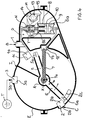
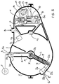
- Figures 1 to 5 illustrate a first embodiment of a rotary switch according to the invention in different positions corresponding respectively to a closed position, an intermediate open position, an open position, an intermediate position of switch and a grounding position for the switch.
- FIG. 6 illustrates an alternative embodiment of a switch according to the invention, in different positions corresponding to the different opening and closing stages previously mentioned.
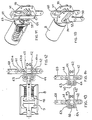
- Figure 7 illustrates a perspective view of a first embodiment of the mechanism actuating the contacts of the vacuum interrupter used in the invention.
- Figure 8 illustrates a sectional view of the previous figure.
- Figure 9 illustrates in a sectional view, an alternative embodiment of the mechanism the bulb contacts.
- Figures 10 to 12 respectively illustrate a perspective view, a perspective view with cutaway, and a sectional view of the previous mechanism and Figures 13 and 14 two views in partial section of this same mechanism.
- FIGS. 1 to 6 we see a three-pole medium voltage switch with gas isolation.
- This switch I is housed in an insulating enclosure E containing the active parts of the switch, which is placed in a waterproof steel or metallized tank (not shown).
- the aforementioned tank contains an insulating gas preferably maintained at a pressure close to atmospheric pressure, while the pressure inside the insulating envelope E will preferably be equal to or greater than this pressure.
- the wall of enclosure E can be that of a gas-insulated installation or station or that of a pole or of the three poles of switch I.
- this switch I comprises mainly inside the aforementioned insulating enclosure E and by pole: three studs 1, 2, 3 sealingly crossing the wall of the enclosure E, a disconnector or conductive bridge 4, consisting of two non-parallel blades 5, 6, carried by a control shaft A extending in the axis of the envelope E, said shaft A being connected to a control mechanism exterior (not shown), and a vacuum interrupter 8 comprising a fixed contact 9 and a movable contact 10 electrically connected respectively to two interior studs 12 and 11 of enclosure E, said movable contact 10 being connected to an actuation mechanism M.
- first 1 of the studs crossing the enclosure wall E is electrically connected inside the enclosure has an internal stud 11, carrying a first fixed contact 1a and forms outside of the enclosure, a connection range 1b to a busbar B.
- the second stud 2 forms outside the enclosure, a connection range 2b to electrical cables C and to inside a second fixed contact 2a.
- the third stud 3 crossing the wall of the enclosure forms outside of this enclosure a connection range 3b to earth T and to inside the enclosure a third fixed contact 3a.
- These three fixed contacts 1a, 2a, 3a are intended to cooperate with two movable contacts 5a, 6a formed respectively at the ends free of the blades 5, 6 of the driver bridge 4.
- the switch I further comprises a switching finger 7, one of the ends 7a of which is articulated around the same axis X as the disconnector 4 and the other end of which 7b is capable of come into contact with pad 12 called switching pad, said pad 12 being placed at inside the enclosure E and electrically connected to the fixed contact 9 of the bulb 8.
- This finger switch 7 is mechanically connected to bridge 4 so as to be rotated by said bridge, in the direction of opening of the switch I, as soon as the movable contact 5a exceeds the switching pad 12 and, in the closing direction, until this same contact 5a again passes in front of the switching pad 12.
- the aforementioned second fixed contact 2a has a range contact 2c greater than the first fixed contact 1, this making it possible to establish the opening and closing sequences of the first and second movable contacts 5a, 6a.
- the actuation mechanism M of the vacuum interrupter 8 mainly consists of a cam 13 moved by a control mechanism (not shown) mechanically connected to the drive shaft A of the driver bridge 4, said cam 13 actuating two levers 14, 15 acting on a movable assembly N carrying the movable contact 10 of the vacuum interrupter 8.
- this switch I comprises substantially the same elements as that of the previous embodiment a few differences close. These differences are mainly due to the fact that the switching finger 16, of a length less than that of the previous embodiment, is mounted articulated by one of its ends 16a directly on the switching pad 12, while its opposite end 16b, cooperates with the first fixed contact 1a and the conductive bridge 4.
- the ground connection pad 3 is located between the two fixed contacts 1a, 2a on the side of the switching pad 12, unlike the first embodiment in which it is located on the side opposite to the switching pad 12, and the two fixed contacts 1a, 2a, have extended contact areas 1c, 2c.
- the conductive bridge consists of two blades 5, 6 parallel, and that the first fixed contact 1a is connected to cables C while the second fixed contact 2a is connected at the busbar B.
- This switch I also includes latching means or hooking (not shown) of the movable contact Sa on the switching finger 16 allowing the disconnector 4 to drive said finger 16 over a certain rotation stroke of the disconnector 4, and means for automatically returning this finger 16 to a position in which it is again in contact with the first fixed contact 1a.
- this vacuum switch D comprises a bulb 8 constituted mainly of a substantially cylindrical casing 8a containing two contacts respectively fixed and mobile 9, 10, the fixed contact 9 being electrically connected to the pad switching 12 previously mentioned, while the movable contact 10 is mounted sliding through one 8b of the bottoms of the envelope 8a while being connected to a mechanism actuation M.
- this mechanism M comprises a cam 13 rotated by a shaft 21 coupled to the control shaft A of the driver bridge 4, said cam 13 acting on two levers 14, 15 mounted articulated by one of their ends 14a, 15a, about the same axis Y and of which the two opposite ends 14b, 15b form two arms in opposition cooperating with the cam 13.
- This mobile assembly N comprises two shaped parts substantially cylindrical 22, 23 respectively exterior and interior, provided with a bottom 22a, 23a, sliding one inside the other, said parts 22, 23 comprising orifices 22b, 23b facing each other intended to allow the passage of the two aforementioned levers 14, 15, said levers 14, 15 being supported on two axes 30, 31 integral with the inner cylinder 23 and sliding through other lights 22c formed in the outer cylinder 22.
- a set of elastic washers 32 is interposed between the two cylinders 22, 23, having been compressed during mounting between the two bottoms 22a, 23a of said parts 22, 23.
- This movable assembly N is guided in translation by means of two machined slots 33a respectively in two flanges 33, 34 located on either side of the mechanism M and it serving as a support.
- the actuation mechanism M of the bulb comprises, a stud 40 secured to the movable contact 10 of the bulb 8, said pad 40 being provided on its two respectively upper faces and lower 40a, 40b, of a semi-spherical recess intended to accommodate one of the ends of the two links 41, 42, the two opposite ends 41a, 42a of which are held by two flexible contact blades 43, 44 mounted in opposition.
- these parts are preferably made of copper alloy.
- Blades forming a spring 45, 46 are applied to the contact blades 43, 44 and maintain the pressure of the contacts hoses 43, 44 on the rods 41, 42 and on the pad 40.
- Figures 10 to 14 show another embodiment of an actuating mechanism M operating according to the same principle as that of FIG. 9 but whose structure differs substantially like that of this figure.
- all of the aforementioned constituents is housed in a support 70 which also performs the function of guiding the movable contact 10, and of the pad 40.
- the two links 41, 42 each have one end housed in a semispherical housing 60a provided in a fixed support 60 and one end housed in a recess 63a, 64a provided in two contact blades 63, 64 belonging to the same room.
- the links 41, 42 are held elastically between the support 60 and the blades contact 63, 64 by the spring blades 61, 62.
- the switch I is in the closed position. In this position, the two movable contacts 5a, 6a of the disconnector 4 are positioned respectively on the two fixed contacts 1a and 2a and the switching finger 7 is in contact with the pad switching 12.
- the vacuum interrupter 8 is in the closed position, however, the main part current from the electric cables C passes through the fixed stud 2, the bridge conductor 4, the fixed block 11 and the block 1 connected to the busbar B, without passing through the vacuum switch D.
- the driver bridge 4 having been driven in the direction when switch I opens (see arrow), the first movable contact Sa on deck 4 is not no longer in contact with the first fixed contact 1a, while the second movable contact 6a is still in contact with the second fixed contact 2a thanks to its extended contact range.
- the switching finger 7 is always in contact with the contact switching 12, so that as soon as the first mobile contact 5a has left the first fixed contact 1a, the current flows through the switching finger 7, the switching pad 12, the vacuum interrupter 8, to the fixed pad 1.
- the vacuum interrupter 8 opens and interrupts the nominal current.
- the first mobile contact Its bridge 4 is superimposed on the switching finger 7 and drives it towards the open position, at the same time as the second movable contact 6a leaves the second contact fixed 2a a in order to obtain the sectioning (FIG. 3). In this position the disconnector 4 and the bulb 8 are open.
- the bridge driver 4 is driven in the opposite direction to the previous one.
- the first contact mobile 5a driving the switching finger 7 in its course, passes in front of the stud switching 12 without touching it, while switching finger 7 comes into contact with this pad 12. From this moment, the switching finger 7 is detached from the contact mobile 5a which continues its rotational travel until the first fixed contact 1a, while the second movable contact 6a slides on the second fixed contact 2a.
- the vacuum interrupter 8 which remains open until instant, closes (figure 1).
- the movable contacts 5a, 6a of the bridge 4 and the finger 7 are driven simultaneously to the disconnector position of closed ground, illustrated in figure 5, from the open position illustrated in figure 3.
- the switching finger 7 plays no role, just like the vacuum bulb 8 which remains opened. Note that the latter can close, if for construction reasons the actuator brings it to this state, but this has no influence on the closing on short circuit.
- the earthing switch opens, the movable contacts 5a, 6a and the switching finger 7 are driven simultaneously to the open position (see figure 3).
- the vacuum interrupter 8 remains open, or else if it had closed when closed at the earth, it opens again.
- the switch I is closed when the conductive bridge 4 connects the first and second fixed contacts 1a, 2a, as illustrated at A, the vacuum interrupter 8 remaining closed, the main current flowing from the first contact fixed 1a connected to cables C, through bridge 4 and second contact 2a connected to busbar B.
- the driver bridge 4 is driven in the direction of the arrow and drives in its travel the switching finger 16 which was in position D, to a position E.
- the vacuum interrupter 8 opens and interrupts the nominal current.
- the finger 16 disengages of the movable contact 5a and is brought back via a contact reminder system with the first fixed contact 1a.
- the movable contact 5a then continues its course until the open position shown in C to obtain sectioning.
- the movable contacts 5a, 6a of the bridge 4 rotate in the closing direction until position A.
- the movable contact Sa of bridge 4 passes at the finger of switching 16, the Sa contact on the finger 16 is hooked, of the ratchet type, allowing a new drive of the finger 16 during a new opening maneuver.
- the vacuum interrupter 8 closes.
- the closing operation of the earthing switch is carried out when the driver bridge 4 connects the stud 3 connected to earth, to the fixed contact 1a connected to the cables presenting as the second fixed contact 2a, an extended contact range 1c.
- Figures 1 to 6 have been described as illustrating a switch incorporating a vacuum interrupter designed to cut off the nominal current, these figures can also be considered to describe a circuit breaker in which the vacuum interrupter is designed to cut off a short-circuit current.
- the lower axis 31 drives the inner cylinder 23 downward, which via elastic washers 32, drives the movable contact 10 and the outer cylinder 22.
- the displacement of the pad 40 causes the displacement of the rods 41,42, the contact blades 43,44, the leaf springs 45,46, and of the movable contact 10 to the position shown in dotted lines.
- the displacement of the lug 51 integral with the stud 40 is effected by means of the crank 50 comprising the light 52 authorizing a dead stroke of this crank 50 before actuate the lug 51, said dead stroke making it possible to sequence the opening and the bulb 8 closed relative to those of the disconnector.
- FIGS. 13 and 14 illustrate the mechanism in two positions corresponding respectively to a position opening of the contacts 9, 10 of the bulb 8 and a closed position of said contacts.
- the form of flexible contacts could be arranged so as to generate an attraction between said contacts, as a function of the intensity which passes through them, this in order to provoke an effort antagonistic to the repulsion effort of the contacts of the bulb.
- the invention has therefore made it possible to solve the problem of incorporating the cut in the only opening maneuver (cut) which generates a sequence of particular functioning, the realization of this sequence being made complex because significant deviations from the stroke characteristics of gas-operated devices insulating at atmospheric pressure compared to devices operating in a vacuum.
Landscapes
- High-Tension Arc-Extinguishing Switches Without Spraying Means (AREA)
- Rotary Switch, Piano Key Switch, And Lever Switch (AREA)
Description
- une ampoule à vide renfermant un contact fixe et un contact mobile mu en translation par un mécanisme d'actionnement couplé au mécanisme de commande précité, l'un, dit premier, des contacts de l'ampoule étant relié électriquement au premier contact fixe précité de l'interrupteur, tandis que l'autre, dit second, est relié électriquement et temporairement au pont par des moyens de commutation ;
- et des moyens de séquencement destinés à établir les séquences d'ouverture et de fermeture des contacts mobiles de l'interrupteur et de l'ampoule coopérant avec les moyens de commutation précités de façon qu'en position de fermeture, les contacts de l'ampoule soient fermés, le second contact de l'ampoule étant relié électriquement au pont conducteur , que pendant la manoeuvre d'ouverture, l'arc associé aux premiers contacts fixe et mobile commute à travers l'ampoule, qu'après un certain degré d'ouverture les contacts de l'ampoule s'ouvrent de manière à réaliser la coupure du circuit électrique, et que pendant la manoeuvre de fermeture de l'interrupteur, les contacts de l'ampoule ne se ferment qu'après la fermeture des premier et second contacts de l'interrupteur.
Claims (21)
- Interrupteur électrique multipolaire moyenne tension du genre comprenant une enveloppe (E) remplie d'un gaz d'isolation et renfermant par pôle, un premier et un second contact fixe situés le long de la paroi interne de l'enveloppe et reliés respectivement à une borne d'entrée et une borne de sortie, lesdits contacts fixes coopérant respectivement avec un premier et un second contacts mobiles portés par un pont (4) conducteur mobile en rotation entraíné par un mécanisme de commande pour établir ou interrompre le circuit électrique entre la première et la seconde borne de raccordement,
caractérisé en ce qu'il comporte en outre :une ampoule à vide (8) renfermant un contact fixe (9) et un contact mobile (10) mu en translation par un mécanisme d'actionnement (M) couplé au mécanisme de commande précité, l'un (10) des contacts de l'ampoule, dit premier contact d'arc, étant relié électriquement au premier contact fixe (1a) de l'interrupteur (I),des moyens de commutation reliant électriquement et temporairement l'autre (9) des contacts de l'ampoule, dit second contact d'arc, au pont conducteur (4),et des moyens de séquencement destinés à établir les séquences d'ouverture et de fermeture des contacts mobiles de l'interrupteur (I) et de l'ampoule (8) coopérant avec les moyens de commutation précités (7, 12, 16) de façon qu'en position de fermeture, les contacts (9, 10) de l'ampoule (8) soient fermés et le second contact de l'ampoule (8) relié électriquement au pont conducteur (4), que lors d'une manoeuvre d'ouverture de l'interrupteur, l'arc associé aux premiers contacts fixe et mobile de l'interrupteur (1a et 5a) commute à travers l'ampoule (8), qu'après un certain degré d'ouverture les contacts d'arc (9, 10) de l'ampoule (8) s'ouvrent de manière à réaliser la coupure du circuit électrique, et que pendant la manoeuvre de fermeture de l'interrupteur (I), les contacts (9, 10) de l'ampoule (8) ne se ferment qu'après la fermeture des premiers et seconds contacts fixe et mobile de l'interrupteur (I). - Interrupteur selon la revendication 1, caractérisé en ce que les moyens de commutation (7, 12, 16) comprennent un plot de commutation (12) relié électriquement au second contact d'arc (9) de l'ampoule (8) et un doigt de commutation (7, 16) dont l'une des extrémités (7a, 16a) est articulée autour d'un axe sensiblement parallèle ou bien concourant à l'axe (X) de rotation du pont conducteur (4), ledit doigt (7, 16) reliant électriquement le pont (4) au plot précité (12) pendant la commutation de l'arc et la coupure du circuit.
- Interrupteur selon la revendication 2, caractérisé en ce que l'une (7a) des extrémités du doigt de commutation (7), est reliée de manière articulée et électriquement au pont (4), en un point intermédiaire de celui-ci, tandis que son autre extrémité (7b) est susceptible de venir et de rester en contact avec le plot de commutation (12) pendant la commutation et la coupure du courant.
- Interrupteur selon la revendication 2, caractérisé en ce que le pont conducteur (4) comporte des moyens d'entraínement en rotation du doigt (7), pendant l'ouverture de l'interrupteur ,après la commutation et la coupure du circuit, et lors de la fermeture de l'interrupteur jusqu'au moment où le premier contact mobile (5a) du pont (4) passe devant le plot de commutation (12) préalablement à la fermeture complète de l'interrupteur.
- Interrupteur selon la revendication 1 ou 2, caractérisé en ce que le doigt de commutation (16) est relié de manière articulée et électriquement, par l'une de ses extrémités (16a), au plot de commutation (12), tandis que son autre extrémité (16b) coopère avec le premier contact mobile (5a) du pont (4).
- Interrupteur selon la revendication 5, caractérisé en ce qu'il comporte des moyens de rappel automatique du doigt (16) en position de contact avec le premier contact fixe (1a) de l'interrupteur (I), et des moyens d'accrochage temporaire du doigt (16) sur le premier contact mobile (5a) du pont (4).
- Interrupteur selon l'une quelconque des revendications précédentes, caractérisé en ce que l'un des contacts fixes de l'interrupteur (1a ou 2a) est relié électriquement à des câbles électriques (C), tandis que l'autre (2a ou 1a) est relié electriquement à un jeu de barres (B).
- Interrupteur selon l'une quelconque des revendications précédentes, caractérisé en ce qu'il comporte en outre un quatrième contact fixe (3a) relié à la terre (T), susceptible d'être relié électriquement par le pont conducteur (4) au contact fixe (1a ou 2a) relié aux câbles électriques (C).
- Interrupteur selon l'une quelconque des revendications précédentes, caractérisé en ce que les moyens de séquencement précités comprennent une plage fixe étendue (2c) prévue sur le second contact fixe précité (2a) et une plage fixe restreinte (1c) prévue sur le premier contact fixe (1a).
- Interrupteur selon l'une quelconque des revendications 1 à 8, caractérisé en ce que les moyens de séquencement précités comprennent deux plages fixes étendues (1c, 2c) prévues respectivement sur les deux contacts fixes (1a, 2a).
- Interrupteur selon l'une quelconque des revendications précédentes, caractérisé en ce que le mécanisme d'actionnement (M) du contact d'arc mobile (10) de l'ampoule (8) comprend une came (13) entraínée en rotation par un arbre (21) couplé au mécanisme de commande (A) du pont conducteur (4), ladite came (13) agissant sur deux leviers (14, 15) articulés par l'une de leurs extrémités (14a, 15a) autour d'un même axe (Y), lesdits leviers (14, 15) agissant sur un ensemble (N) monté coulissant dans un support (33, 34) et solidaire du contact mobile (10) de l'ampoule (8), le profil de la came (13) définissant les séquences d'ouverture et de fermeture des contacts (9, 10) de l'ampoule (8).
- Interrupteur selon la revendication 11, caractérisé en ce que l'ensemble mobile (N) comprend deux cylindres (22, 23) comportant un fond (22a, 23a), lesdits cylindres (22, 23) coulissant l'un à l'intérieur de l'autre et comportant des lumières (22b, 23b) en regard destinées au passage des deux leviers (14, 15) entre deux axes (30, 31) solidaires du cylindre intérieur (23) sur lesquels lesdits leviers (14,15) sont en appui, lesdits axes (30, 31) étant montés coulissant par leurs extrémités dans des lumières (22a) ménagées d'une part, dans le cylindre extérieur (22), et d'autre part dans deux flasques (33, 34) appartenant au support du mécanisme (M), des rondelles élastiques (32) étant comprimées au montage entre le fond (23a) du cylindre intérieur (23) et le fond (22a) du cylindre extérieur (22), ledit cylindre extérieur (22a) portant le contact mobile (10) de l'ampoule (8).
- Interrupteur selon l'une quelconque des revendications 1 à 10, caractérisé en ce que le mécanisme d'actionnement M comprend un plot (40) solidaire du contact d'arc mobile (10) et actionné par un mécanisme d'entraínement (50) coopérant avec un système à passage de point mort comprenant deux biellettes (41,42), chacune des biellettes comportant une extrémité logée de manière articulée dans un logement semi-sphérique (40a,40b,63a,64a) appartenant à une première pièce (40,63,64) solidaire en translation du contact d'arc mobile (10) et une extrémité logée de manière articulée dans un logement également semi-sphérique (43a,44a,60a) appartenant à une seconde pièce fixe (43,44,60), lesdites biellettes (41,42) étant maintenues élastiquement entre ces deux pièces (40,43,44et60,63,64), de manière à pouvoir pivoter autour de l'axe du logement semi-sphérique prévu dans la pièce fixe (43) lors du déplacement du contact mobile (10).
- Interrupteur selon la revendication 13, caractérisé en ce que les deux biellettes (41,42) sont logées de manière articulée, par l'une de leurs extrémités, dans deux évidements semi-shériques (40a,40b) prévus respectivement dans deux parois opposées du plot (40), et par leur extrémité opposée, dans deux évidements semi-sphériques (43a,44a) prévus dans deux lames de contact (43,44) montées en opposition, sur lesquelles sont appliquées des lames de ressort (45,46), les lames de contact et de ressort étant fixes par rapport au contact mobile.
- Interrupteur selon la revendication 13, caractérisé en ce que les biellettes (41,42) sont logées de manière articulées, par l'une de leurs extrémités, dans deux évidements semi-sphériques (60a) prévus dans un support fixe (60) et par leurs extrémités opposées, dans deux évidements semi-sphériques (63a,64a) prévus respectivement dans deux lames de contact (63,64) montées en opposition et fixées sur ce dernier.
- Interrupteur à ampoule sous vide destiné notamment à assurer la coupure dans un interrupteur, du genre comprenant une enveloppe sensiblement cylindrique fermée par deux fonds renfermant un contact d'arc fixe et un contact d'arc mobile mu en translation par un mécanisme d'actionnement, caractérisé en ce que le mécanisme d'actionnement (M) comprend une came (13) entraínée en rotation par un arbre (21), ladite came (13) agissant sur deux leviers (14,15) articulés par l'une de leurs extrémités (14a,15a) autour d'un même axe (Y), lesdits leviers (14,15) agissant sur un ensemble (N) monté coulissant dans un support (33,34) et portant le contact mobile (10) de l'ampoule (8), le profil de la came (13) définissant les séquences d'ouverture et de fermeture des contacts (9,10) de l'ampoule (8).
- Interrupteur selon la revendication 16, caractérisé en ce que l'ensemble mobile (N) comprend deux cylindres (22, 23) comportant un fond (22a, 23a), lesdits cylindres (22, 23) coulissant l'un à l'intérieur de l'autre et comportant des lumières (22b, 23b) en regard destinées au passage des deux leviers (14, 15) entre deux axes (30, 31) solidaires du cylindre intérieur (23) sur lesquels lesdits leviers sont en appui, lesdits axes (30, 31) étant montés coulissant par leurs extrémités dans des lumières (33a) ménagées d'une part dans le cylindre extérieur (22), et d'autre part dans deux flasques (33, 34) appartenant au support du mécanisme (M), des rondelles élastiques (32) étant comprimées au montage entre le fond (23a) du cylindre intérieur (23) et le fond (22a) du cylindre extérieur (22), ledit cylindre extérieur (22a) portant le contact d'arc mobile (10) de l'ampoule (8).
- Interrupteur à ampoule sous vide du genre comprenant une enveloppe de forme sensiblement cylindrique fermée par deux fonds et renfermant un contact d'arc fixe et un contact d'arc mobile mu en translation par un mécanisme d'actionnement, caractérisé en ce que le mécanisme précité comprend un plot (40) solidaire du contact mobile (10) et actionné par un mécanisme d'entraínement (50) coopérant avec un système à passage de point mort comprenant deux biellettes (41,42), chacune des biellettes comportant une extrémité logée de manière articulée dans un logement semi-sphérique (40a,40b,63a,64a) appartenant à une première pièce (40,63,64) solidaire en translation du contact d'arc mobile (10) et une extrémité logée de manière articulée dans un logement également semi-sphérique (43a,44a,60a) appartenant à une seconde pièce fixe (43,44,60), lesdites biellettes (41,42) étant maintenues élastiquement entre ces deux pièces (40,43,44 et 60,63,64)), de manière à pouvoir pivoter autour de l'axe du logement (43a,44a,60a) prévu dans la pièce fixe (43) lors du déplacement du contact d'arc mobile (10).
- Interrupteur selon la revendication 8, caractérisé en ce que les deux biellettes (41,42) sont logées de manière articulée, par l'une de leurs extrémités, dans deux évidements semi-shériques (40a,40b) prévus respectivement dans deux parois opposées du plot (40), et par leur extrémité opposée dans deux évidements semi-sphériques (43a,44a) prévus dans deux lames de contact (43,44) montées en opposition, sur lesquelles sont appliquées des lames de ressort (45,46), les lames de contact et de ressort étant fixes par rapport au contact mobile.
- Interrupteur selon la revendication 16, caractérisé en ce que les biellettes (41,42) sont logées de manière articulées, par l'une de leurs extrémités, dans deux évidements semi-sphériques (60a) prévus dans un support fixe (60) et par leurs extrémités opposées, dans deux évidements semi-sphériques (63a,64a) prévus respectivement dans deux lames de contact (63,64) montées en opposition et fixées sur ce dernier.
- Interrupteur selon l'une quelconque des revendications 18 à 20, caractérisé en ce que le plot précité (40) est actionné par une manivelle (50) comportant une lumière (52) dans laquelle coulisse un ergot (51) solidaire du plot (40), ladite lumière (52) permettant de définir les séquences d'ouverture et de fermeture des contacts de l'ampoule.
Applications Claiming Priority (2)
| Application Number | Priority Date | Filing Date | Title |
|---|---|---|---|
| FR9409198 | 1994-07-20 | ||
| FR9409198A FR2722912B1 (fr) | 1994-07-20 | 1994-07-20 | Interrupteurs electriques moyenne tension |
Publications (2)
| Publication Number | Publication Date |
|---|---|
| EP0693763A1 EP0693763A1 (fr) | 1996-01-24 |
| EP0693763B1 true EP0693763B1 (fr) | 2000-04-26 |
Family
ID=9465727
Family Applications (1)
| Application Number | Title | Priority Date | Filing Date |
|---|---|---|---|
| EP19950410067 Expired - Lifetime EP0693763B1 (fr) | 1994-07-20 | 1995-07-04 | Interrupteurs électriques moyenne tension |
Country Status (3)
| Country | Link |
|---|---|
| EP (1) | EP0693763B1 (fr) |
| DE (1) | DE69516461T2 (fr) |
| FR (1) | FR2722912B1 (fr) |
Cited By (3)
| Publication number | Priority date | Publication date | Assignee | Title |
|---|---|---|---|---|
| WO2014001029A1 (fr) | 2012-06-25 | 2014-01-03 | Siemens Aktiengesellschaft | Sectionneur à coupure sous charge à trois positions pour installations électriques moyenne tension |
| DE102013217834A1 (de) * | 2013-09-06 | 2015-03-12 | Siemens Aktiengesellschaft | SF6-freies Schaltgerät |
| US12444559B2 (en) | 2022-05-12 | 2025-10-14 | Abb Schweiz Ag | Medium voltage switching apparatus |
Families Citing this family (12)
| Publication number | Priority date | Publication date | Assignee | Title |
|---|---|---|---|---|
| ES2212747B1 (es) * | 2003-01-14 | 2005-06-01 | Grupo Ormazabal, S.A. | Centro de transformacion para transformador autoprotegido. |
| DE102006008933B4 (de) * | 2006-02-22 | 2009-06-18 | Siemens Ag | Elektrisches Schaltgerät |
| WO2011147717A1 (fr) * | 2010-05-25 | 2011-12-01 | Siemens Aktiengesellschaft | Commutateur de rupture de charge |
| DE202010009448U1 (de) * | 2010-06-23 | 2010-09-09 | Ipt International Power & Technology Gmbh | Hochspannungsschaltvorrichtung |
| DE102012200962B4 (de) * | 2012-01-24 | 2018-07-26 | Siemens Aktiengesellschaft | Schaltgerät, insbesondere Lasttrennschalter, für Mittelspannungs-Schaltanlagen |
| EP3046129B1 (fr) * | 2015-01-15 | 2019-09-11 | Schneider Electric Industries SAS | Système de rupture de shunt |
| CN105990068B (zh) * | 2015-02-10 | 2019-10-18 | 施耐德电器工业公司 | 分流断路系统 |
| DE102018109750B4 (de) * | 2018-04-23 | 2023-11-23 | Fritz Driescher KG Spezialfabrik für Elektrizitätswerksbedarf GmbH & Co. | Schaltvorrichtung |
| CN113826181B (zh) * | 2019-03-29 | 2024-06-07 | 西门子股份公司 | 优化的三位开关 |
| EP4276871B1 (fr) * | 2022-05-12 | 2026-03-18 | ABB Schweiz AG | Procédé d'assemblage d'un appareil de commutation pour systèmes électriques à moyenne tension et ensemble de montage pour un appareil de commutation à moyenne tension |
| EP4276874B1 (fr) | 2022-05-12 | 2025-04-30 | ABB Schweiz AG | Appareil de commutation moyenne tension |
| CN121909524A (zh) * | 2023-09-25 | 2026-04-21 | 西门子能源国际公司 | 用于补偿真空开关管中压力的盘形凸轮传动装置 |
Family Cites Families (5)
| Publication number | Priority date | Publication date | Assignee | Title |
|---|---|---|---|---|
| GB1126362A (en) * | 1965-07-06 | 1968-09-05 | Ass Elect Ind | Improvements in and relating to electric circuit breakers |
| GB1156919A (en) * | 1965-12-23 | 1969-07-02 | Ass Elect Ind | Improvements in and relating to Circuit Breakers |
| FR2655766B1 (fr) | 1989-12-11 | 1993-09-03 | Merlin Gerin | Disjoncteur hybride moyenne tension. |
| FR2668851B1 (fr) | 1990-11-06 | 1994-10-07 | Merlin Gerin | Interrupteur rotatif multipolaire. |
| FR2682807B1 (fr) * | 1991-10-17 | 1997-01-24 | Merlin Gerin | Disjoncteur electrique a deux cartouches a vide en serie. |
-
1994
- 1994-07-20 FR FR9409198A patent/FR2722912B1/fr not_active Expired - Fee Related
-
1995
- 1995-07-04 EP EP19950410067 patent/EP0693763B1/fr not_active Expired - Lifetime
- 1995-07-04 DE DE1995616461 patent/DE69516461T2/de not_active Expired - Fee Related
Cited By (4)
| Publication number | Priority date | Publication date | Assignee | Title |
|---|---|---|---|---|
| WO2014001029A1 (fr) | 2012-06-25 | 2014-01-03 | Siemens Aktiengesellschaft | Sectionneur à coupure sous charge à trois positions pour installations électriques moyenne tension |
| DE102013217834A1 (de) * | 2013-09-06 | 2015-03-12 | Siemens Aktiengesellschaft | SF6-freies Schaltgerät |
| DE102013217834B4 (de) | 2013-09-06 | 2022-01-20 | Siemens Aktiengesellschaft | Schaltgerät und Verfahren zum Schalten eines solchen Schaltgerätes |
| US12444559B2 (en) | 2022-05-12 | 2025-10-14 | Abb Schweiz Ag | Medium voltage switching apparatus |
Also Published As
| Publication number | Publication date |
|---|---|
| EP0693763A1 (fr) | 1996-01-24 |
| FR2722912B1 (fr) | 1996-09-13 |
| DE69516461D1 (de) | 2000-05-31 |
| DE69516461T2 (de) | 2000-10-12 |
| FR2722912A1 (fr) | 1996-01-26 |
Similar Documents
| Publication | Publication Date | Title |
|---|---|---|
| EP0517620B1 (fr) | Disjoncteur moyenne tension à énergie de commande réduite | |
| EP0847586B1 (fr) | Disjoncteur hybride a haute tension | |
| EP0680063B1 (fr) | Interrupteur électrique moyenne tension | |
| EP0542637B1 (fr) | Disjoncteur électrique à deux cartouches à vide en série | |
| EP0693763A1 (fr) | Interrupteurs électriques moyenne tension | |
| EP2575155B1 (fr) | Appareillage de distribution électrique moyenne tension | |
| EP1271590A1 (fr) | Dispositif interrupteur pour haute ou moyenne tension à coupure mixte par vide et gaz | |
| EP1090404A1 (fr) | Disjoncteur multipolaire basse tension de tenue electrodynamique elevee, dont l'arbre des poles est dispose dans le compartiment de logement des poles | |
| CA2526344C (fr) | Cinematique d'entrainement dans un disjoncteur hybride | |
| CH674104A5 (fr) | ||
| EP1870916A1 (fr) | Actionnement par came cylindrique d'un disjoncteur sectionneur d'alternateur | |
| EP0599742B1 (fr) | Mécanisme d'ouverture et de fermeture pour interrupteur électrique moyenne ou haute tension | |
| EP0058585A1 (fr) | Mécanisme de manoeuvre pour appareillage de commutation électrique à trois positions distinctes | |
| EP2037470B1 (fr) | Actionnement par un ensemble d'arbre principal et d'arbres secondaires d'un disjoncteur sectionneur d'alternateur | |
| EP2335262A1 (fr) | Appareil de commutation electrique muni de deux interrupteurs, tels qu'un sectionneur de barre et un sectionneur de terre et comprenant des moyens d'entrainement communs aux contacts mobiles des interrupteurs | |
| FR2790592A1 (fr) | Disjoncteur haute tension a double mouvement | |
| FR2744284A1 (fr) | Interrupteur ou disjoncteur multipolaire moyenne tension | |
| EP0053524A1 (fr) | Disjoncteur électrique à autosoufflage par rotation de l'arc | |
| EP1402549A1 (fr) | Appareillage electrique de coupure et de sectionnement comportant une ampoule sous vide | |
| EP0731481B1 (fr) | Disjoncteur auto-sectionneur à sectionnement auto-verrouillé en position fermée des chambres de coupure | |
| EP0689217A1 (fr) | Ampoule sous vide, notamment pour disjoncteur ou interrupteur électrique moyenne tension et interrupteur intégrant une telle ampoule | |
| EP0785562A1 (fr) | Disjoncteur à double mouvement des contacts | |
| CA2281971C (fr) | Interrupteur avec un systeme d'insertion d'une resistance a longue duree d'insertion | |
| EP0750328B1 (fr) | Interrupteur auto-sectionneur | |
| EP0403329A1 (fr) | Perfectionnements aux interrupteurs à coupure automatique, notamment aux disjoncteurs et disjoncteurs différentiels |
Legal Events
| Date | Code | Title | Description |
|---|---|---|---|
| PUAI | Public reference made under article 153(3) epc to a published international application that has entered the european phase |
Free format text: ORIGINAL CODE: 0009012 |
|
| AK | Designated contracting states |
Kind code of ref document: A1 Designated state(s): DE GB NL |
|
| 17P | Request for examination filed |
Effective date: 19960723 |
|
| GRAG | Despatch of communication of intention to grant |
Free format text: ORIGINAL CODE: EPIDOS AGRA |
|
| 17Q | First examination report despatched |
Effective date: 19990624 |
|
| RAP1 | Party data changed (applicant data changed or rights of an application transferred) |
Owner name: SCHNEIDER ELECTRIC INDUSTRIES SA |
|
| GRAG | Despatch of communication of intention to grant |
Free format text: ORIGINAL CODE: EPIDOS AGRA |
|
| GRAH | Despatch of communication of intention to grant a patent |
Free format text: ORIGINAL CODE: EPIDOS IGRA |
|
| GRAH | Despatch of communication of intention to grant a patent |
Free format text: ORIGINAL CODE: EPIDOS IGRA |
|
| RAP1 | Party data changed (applicant data changed or rights of an application transferred) |
Owner name: SCHNEIDER ELECTRIC INDUSTRIES SA |
|
| GRAA | (expected) grant |
Free format text: ORIGINAL CODE: 0009210 |
|
| AK | Designated contracting states |
Kind code of ref document: B1 Designated state(s): DE GB NL |
|
| REF | Corresponds to: |
Ref document number: 69516461 Country of ref document: DE Date of ref document: 20000531 |
|
| GBT | Gb: translation of ep patent filed (gb section 77(6)(a)/1977) |
Effective date: 20000530 |
|
| PLBE | No opposition filed within time limit |
Free format text: ORIGINAL CODE: 0009261 |
|
| STAA | Information on the status of an ep patent application or granted ep patent |
Free format text: STATUS: NO OPPOSITION FILED WITHIN TIME LIMIT |
|
| 26N | No opposition filed | ||
| REG | Reference to a national code |
Ref country code: GB Ref legal event code: IF02 |
|
| PGFP | Annual fee paid to national office [announced via postgrant information from national office to epo] |
Ref country code: GB Payment date: 20020703 Year of fee payment: 8 |
|
| PGFP | Annual fee paid to national office [announced via postgrant information from national office to epo] |
Ref country code: NL Payment date: 20020730 Year of fee payment: 8 |
|
| PG25 | Lapsed in a contracting state [announced via postgrant information from national office to epo] |
Ref country code: GB Free format text: LAPSE BECAUSE OF NON-PAYMENT OF DUE FEES Effective date: 20030704 |
|
| PG25 | Lapsed in a contracting state [announced via postgrant information from national office to epo] |
Ref country code: NL Free format text: LAPSE BECAUSE OF NON-PAYMENT OF DUE FEES Effective date: 20040201 |
|
| GBPC | Gb: european patent ceased through non-payment of renewal fee |
Effective date: 20030704 |
|
| NLV4 | Nl: lapsed or anulled due to non-payment of the annual fee |
Effective date: 20040201 |
|
| PGFP | Annual fee paid to national office [announced via postgrant information from national office to epo] |
Ref country code: DE Payment date: 20040709 Year of fee payment: 10 |
|
| PG25 | Lapsed in a contracting state [announced via postgrant information from national office to epo] |
Ref country code: DE Free format text: LAPSE BECAUSE OF NON-PAYMENT OF DUE FEES Effective date: 20060201 |