EP0692181B1 - Shaker members for grape harvester - Google Patents
Shaker members for grape harvester Download PDFInfo
- Publication number
- EP0692181B1 EP0692181B1 EP95201900A EP95201900A EP0692181B1 EP 0692181 B1 EP0692181 B1 EP 0692181B1 EP 95201900 A EP95201900 A EP 95201900A EP 95201900 A EP95201900 A EP 95201900A EP 0692181 B1 EP0692181 B1 EP 0692181B1
- Authority
- EP
- European Patent Office
- Prior art keywords
- rod
- machine
- rods
- machine according
- shaker
- Prior art date
- Legal status (The legal status is an assumption and is not a legal conclusion. Google has not performed a legal analysis and makes no representation as to the accuracy of the status listed.)
- Expired - Lifetime
Links
- 240000006365 Vitis vinifera Species 0.000 title description 6
- 235000014787 Vitis vinifera Nutrition 0.000 title description 6
- 235000009754 Vitis X bourquina Nutrition 0.000 title description 3
- 235000012333 Vitis X labruscana Nutrition 0.000 title description 3
- 238000003306 harvesting Methods 0.000 claims description 17
- 235000013399 edible fruits Nutrition 0.000 claims description 16
- 230000007246 mechanism Effects 0.000 claims description 13
- 239000000463 material Substances 0.000 claims description 12
- 230000033001 locomotion Effects 0.000 claims description 11
- 235000021028 berry Nutrition 0.000 claims description 4
- 241000219094 Vitaceae Species 0.000 description 17
- 235000021021 grapes Nutrition 0.000 description 17
- 238000010009 beating Methods 0.000 description 5
- 230000010355 oscillation Effects 0.000 description 5
- 241000196324 Embryophyta Species 0.000 description 4
- 239000007787 solid Substances 0.000 description 4
- 238000005452 bending Methods 0.000 description 3
- 230000008878 coupling Effects 0.000 description 2
- 238000010168 coupling process Methods 0.000 description 2
- 238000005859 coupling reaction Methods 0.000 description 2
- 230000003247 decreasing effect Effects 0.000 description 2
- 230000009474 immediate action Effects 0.000 description 2
- 230000008092 positive effect Effects 0.000 description 2
- 241001091440 Grossulariaceae Species 0.000 description 1
- 241001124569 Lycaenidae Species 0.000 description 1
- 206010067482 No adverse event Diseases 0.000 description 1
- 229920002302 Nylon 6,6 Polymers 0.000 description 1
- 239000004952 Polyamide Substances 0.000 description 1
- 235000002357 Ribes grossularia Nutrition 0.000 description 1
- 235000016954 Ribes hudsonianum Nutrition 0.000 description 1
- 240000001890 Ribes hudsonianum Species 0.000 description 1
- 235000001466 Ribes nigrum Nutrition 0.000 description 1
- 244000235659 Rubus idaeus Species 0.000 description 1
- 241000533293 Sesbania emerus Species 0.000 description 1
- 230000009471 action Effects 0.000 description 1
- 230000005540 biological transmission Effects 0.000 description 1
- 230000007423 decrease Effects 0.000 description 1
- 230000001627 detrimental effect Effects 0.000 description 1
- 238000006073 displacement reaction Methods 0.000 description 1
- 239000000428 dust Substances 0.000 description 1
- 239000003365 glass fiber Substances 0.000 description 1
- 235000019674 grape juice Nutrition 0.000 description 1
- 230000036541 health Effects 0.000 description 1
- 230000001771 impaired effect Effects 0.000 description 1
- 230000001788 irregular Effects 0.000 description 1
- 238000004519 manufacturing process Methods 0.000 description 1
- 230000004048 modification Effects 0.000 description 1
- 238000012986 modification Methods 0.000 description 1
- 230000035515 penetration Effects 0.000 description 1
- 229920002647 polyamide Polymers 0.000 description 1
- 229920000728 polyester Polymers 0.000 description 1
- 238000013138 pruning Methods 0.000 description 1
- 235000021013 raspberries Nutrition 0.000 description 1
- 230000009467 reduction Effects 0.000 description 1
- 238000009877 rendering Methods 0.000 description 1
- 238000005507 spraying Methods 0.000 description 1
- 230000000007 visual effect Effects 0.000 description 1
- 239000013585 weight reducing agent Substances 0.000 description 1
Images



Classifications
-
- A—HUMAN NECESSITIES
- A01—AGRICULTURE; FORESTRY; ANIMAL HUSBANDRY; HUNTING; TRAPPING; FISHING
- A01D—HARVESTING; MOWING
- A01D46/00—Picking of fruits, vegetables, hops, or the like; Devices for shaking trees or shrubs
- A01D46/28—Vintaging machines, i.e. grape harvesting machines
Definitions
- the present invention relates to a machine for harvesting fruits, berries and the like, from fruit trees and bushes planted in rows, and more particularly, although not exclusively, to a machine for harvesting grapes.
- the machine of the present invention equally well is capable of being used for harvesting other fruits and berries, for example black currants, gooseberries, raspberries or coffee beans.
- This principle consists of beating or shaking the vines by imparting sinusoidal or pseudo-sinusoidal motion thereto at an amplitude and at a frequency suitable for causing the grapes or the bunches of grapes to become detached.
- This motion is transmitted to the vine via shaker or beater members disposed in such a manner as to act either on the vinestock or stem or else on the vegetation, i.e. on the fruit-bearing portion of the vine, depending on the type and number of shaker or beater members used.
- the percentage of bunches and/or individual grapes which are detached from the vines depends on the number and the amplitude of the oscillations to which a given bunch of grapes is subjected. The more energetic the shaking to which a given bunch of grapes is subjected, and the more frequently it is shaken, the more likely said bunch or its individual grapes are to become detached from the vine.
- the number and the amplitude of the above oscillations depend on various parameters that may be selected, in particular on the amplitude and the frequency of the drive mechanism associated with the shaker or beater members, on the length of the active shaking zone of said shaker or beater members, on the stiffness or the flexibility thereof, and on the speed at which the machine advances, together with other factors which are imposed by the vine itself, in particular the way it is trained, its shape, and the resistance it gives to the motions of the beater or shaker members.
- the shaker or beater members when too energetically moved, may damage the vines, at least to some extent, which may be detrimental to the health of the crop. It is therefore generally necessary to find a compromise between the various above-mentioned parameters in order to obtain an acceptable percentage of harvested grapes or bunches of grapes without giving rise to unacceptable damage to the vines.
- the shaking or beating frequency again has to be increased.
- a machine for harvesting fruits, berries and the like, from fruit trees and bushes planted in rows, the machine comprising :
- each rod comprises at least one cavity to reduce the weight thereof.
- the cavity is in the form of a central, cylindrical bore extending in the longitudinal direction of the rod.
- the rod ends are closed by plug members to prevent any material to accumulate in the bore.
- the harvesting machine shown in Figures 1 and 2 is a grape harvester and comprises, in a conventional manner, a chassis 1 provided with front steerable wheels 2 and rear traction wheels 3 for moving the chassis 1 over the ground.
- the chassis 1 is in the from of a gantry in order to be able to straddle a row of plants.
- the chassis 1 carries a harvesting assembly 4 comprising a shaker assembly 5 and two elevator conveyors 6 for collecting the grapes that have been detached by the shaker assembly 5 in order to convey them to a temporary storage tank 7 (generally two tanks are provided on respective sides of the machine).
- the chassis also has an engine 8 providing the rotational power necessary to drive the various active members of the machine and also for providing motive power to the wheels in case the machine is of the self-propelled type.
- the harvesting assembly 4 may be fixed in a permanent manner to the chassis 1 of the machine or else it may be made in the form of a removable assembly which is detachably fixed to the chassis 1 so as to be capable of being replaced by other equipment or accessories, such as spraying equipment, pruning equipment, equipment for tilling the ground, etc.
- the harvesting assembly 4 can therefore either be supported directly by the chassis 1 of the machine or else it may be supported by an auxiliary chassis 9.
- the auxiliary chassis 9 may be mounted fixedly relative to the chassis 1 or it may be pivotally mounted thereon with its top portion being pivotally attached to a horizontal, fore-and-aft extending axis for swinging movement therearound.
- the shaker assembly 5 comprises two sets 10a and 10b of shaker members 11, with the two sets 10a and 10b being disposed facing one another on opposite sides of the longitudinal median plane 12 of the machine.
- each set e.g. the set 10a
- shaker assembly shown in Figures 1 to 3 comprise two sets of six shaker members, it is obvious that the number may be decreased or increased depending on types of fruit tree or bush, and for a given type of fruit tree or bush depending on the variety, the way in which it has been trained, and the shape of the vegetation of the fruit trees or bushes. Variations may also depend on whether it is desired to shake the fruit trees or bushes by their trunks or by their vegetation.
- Each shaker member 11 is constituted by a flexible rod whose cross-section is very small compared to its length and as can be seen more particularly in Figures 4 and 5, each rod 11 is curved to form an arc.
- the rods used may be pre-curved on manufacture but preferably they are rectilinear, in which case they are curved by bending when mounted on the shaking assembly 5.
- each rod 11 is firmly clamped in a clamp 13a which is rigidly fixed to a vertical support plate 13 (with one plate 13 being provided for each of the two sets 10a and 10b of rods 11).
- Each plate 13 is provided at each of its ends with a vertically oriented stub axle 14 rotatably received in a bearing 15 fixed on the auxiliary chassis 9.
- the other end of each rod 11 is fixed in a support 16 which is hinged about a vertical axis 17 at one of the ends of a short link 18 whose other end is hinged to the auxiliary chassis 9 about a vertical axis 19.
- a drive device 20 producing a reciprocating motion is connected to the support plate 13 on one of the two sets 10a and 10b of rods 11 in order to cause the plate 13 to oscillate about the axis of the stub axles 14.
- the drive device 20 may be constituted, for example, by a connecting rod and crank system whose shaft 21 is rotatable in bearings 22 (as seen in Figures 3 and 5) which are fixed to the auxiliary chassis 9.
- the shaft 21 may be rotated by any appropriate transmission (not shown) connected to the output shaft of a motor, for example the motor 8 of the harvesting machine.
- One of the ends of the connecting rod 24 is hinged to a crank pin 23 of the connecting rod and crank pin system 20 while its opposite end is hinged about an axis 25 to a horizontal arm 26 which is rigidly fixed to the support plate 13 for the set 10a of rods 11.
- Two other horizontal arms 27 extend substantially parallel to the longitudinal median plane 12 of the machine and are rigidly fixed to respective ones of the two vertical plates 13.
- the arms 27 are interconnected by a horizontal and transverse coupling rod 28 which ends are hinged to respective ones of the free ends of the arms 27 about axes 29.
- the coupling rod 28 is in the form of a rod of which the length is adjustable, such as by a turnbuckle as shown in Figure 4, in order to enable the symmetrical adjustment of the two sets 10a and 10b of the rods 11 relative to the median plane 12 of the machine.
- the support plates 13 are at the front ends of the rods 11, whereas the supports 16 and the links 18 are at the rear ends of the rods 11, even though the opposite configuration could equally well be used.
- the arcuate shape of the flexible rods 11 in the two sets 10a and 10b form, between said sets, a converging inlet zone for fruit trees and bushes, followed by an active shaking zone extending over a length 1 as approximately indicated in Figure 4, which in turn is followed by a diverging outlet zone for the fruit trees or bushes.
- the flexible rods 11 of the set 10a are at minimum curvature when the flexible rods 11 of the set 10b are at maximum curvature (position B), and conversely that the rods 11 of the set 10a are at maximum curvature when the rods 11 of the set 10b are at minimum curvature (position D). It can also be seen that while the rods 11 are bending from their minimum curvature position towards their maximum curvature position, their front and rear ends remain at a substantially constant distance from the longitudinal median plane 12, whereas the active shaking zone l reciprocates transversely on either side of said longitudinal plane 12.
- the amplitude of the transverse movement of the active portion of the flexible rods 11 depend on their maximum and minimum values of curvature which in turn depend on the eccentricity of the crank pin 23 relative to the axis of the shaft 21.
- the eccentricity of the crank pin 23 is adjustable in known manner in order to make it possible to adjust the amplitude of the transverse motion of the active portion of the flexible rods 11.
- the connecting rod 24 is also provided in the form of a rod of variable length in order to make it possible to adjust the average position (positions A, C) of the rods 11 so that the distance e between the active portions of the rods in the two sets 10a and 10b respectively can be adjusted.
- Figure 6 shows how the flexible rods 11 of the shaker assembly of a harvesting machine in accordance with the present invention are capable of adapting individually to the thickness of the vegetation 30 on a fruit tree or bush such as a vine plant.
- a vine plant arrives in the converging inlet portion between the two sets 10a and 10b of rods 11, the vegetation applies forces to the rods 11 such that the longitudinal components thereof are transmitted by said rods to the links 18 which pivot rearwardly about their axes 19.
- the rods 11 deform elastically (their curvature decreases) and move further and further away from the longitudinal median plane 12 depending on the thickness of the vegetation at the height of each rod 11.
- Each shaker member 11 is made of a material which is very flexible and deformable, for example a polyamide or a glass fibre reinforced polyester.
- a material which is very flexible and deformable for example a polyamide or a glass fibre reinforced polyester.
- good results have been obtained on vines when using solid rods having a circular section with a diameter in the range of 25 to 30 mm and a length of approximately 2 m made of a polyamide 66 type of which the modulus of elasticity E is equal to approximately 3000 N/mm 2 .
- a maximum operating frequency of about 7,2 Hz i.e.
- an individual rod 11 is shown having a rectilinear shape being the shape before it is mounted on the shaking assembly 5.
- the rod 11 comprises a front end 32 for being clamped by a clamp 13a and a rear end 34 for attachment to a support 16.
- the mass, and therefore the weight, of each rod 11 is decreased by providing a central cavity therein, preferably in the form of a cylindrical bore 36, indicated in Figures 6 and 7, extending longitudinally along the full length of the rod 11.
- the diameter of the bore is in the range of 10 to 20 mm and the bore is provided to reduce the amount of rod material around the central, longitudinal axis 38 of the rod 11 considering that said material only adds up to the weight of the rod 11 without having any considerable influence on the increase of the rigidity thereof. Reducing the mass of rod material, especially in the region close to the central axis 38, presents an important step in increasing the resonance frequency of the rod 11.
- the outer diameter of the rod 11 is slightly increased when compared to a rod with a solid section to a value inbetween 30 and 35 mm in order to render the rod 11 more rigid, thereby again having a positive effect on the resonance frequency thereof.
- the working frequency of the rod 11 may be increased to more than 8.8 Hz (approximately 530 RPM) without going into resonance.
- a plug member 40 is inserted into the bore 36 on the one hand to prevent foreign material such as dust, grape juice, etc to enter and accumulate into the bore 36 whereby the positive effect of the bore 36 on the resonance frequency would be impaired and on the other hand to reinforce the ends 32 and 34 for avoiding deformation and crushing of said ends when being clamped onto their respective supports 13, 16.
- the plug members 40 may be glued into the bore 36 or fastened in any other convenient manner.
- the plug members 40 are made of material similar to the material of the rods 11.
- a thin electrical wire 42 to which a low voltage is applied, may be run through the bore 36 in each rod 11, all these wires 42 being operatively connected together and linked to a warning or control system (not shown) in the operator's cab.
- the wires 42 are installed into the bores 36 with some play allowing the rods 11 to flex as desired without imparting any damage to the wires 42. As long as all wires are intact, no warning or control signal is generated. However, it will be appreciated that upon rupture of a rod 11, the associated wire 42 also will be snapped, whereby the operator receives an audible or visual alarm signal in his cab enabling him to take immediate action or a control signal may be generated whereby the drive to the shaking mechanism is immediately disengaged.
- the bore 36 should not necessarily extend along the full length of the rod 11, but may stop short of the opposite ends of the rod 11 whereby the plug members 40 are no longer needed.
- the rod 11 may comprise several individual, spherical or oblong cavities, all aiming to reduce the weight of the rod. Considering that, as best seen in Figure 4, the rods 11 are always curved and pretensioned in a given direction, the bore 36 or individual cavities may be provided eccentrically of the central axis 38, preferably offset in the direction of the inward curve or concave side of the rod 11 since the rod material at this location has the least influence on the rigidity of the rod 11.
- the bore 36 may have an irregular cross-sectional shape and may even pierce through the longitudinal side of the rod 11, whereby the bore no longer would be provided fully internally of the rod 11. Still further, instead of rods with a circular cross section, also oval shaped, hollow rods may be employed. A prerequisite of all the above embodiments is to provide the bores or cavities in a region of the rods having only little influence on the rigidity thereof in such a manner that the ratio of the rigidity reduction versus weight reduction is increased leading to higher resonance frequencies.
- the present invention has been described with reference to a shaking mechanism 5 in which the front ends 32 of the shaker rods 11 are fixedly attached to an oscillating drive mechanism 13 while the rear ends 34 are pivotally connected to a link mechanism 18, it will be clear that the invention is applicable to all kinds of shaker or beater mechanisms employing flexible rods.
- the rods may be attached at one end only while the opposite end is free to move and constitutes the active portion of the rod.
Landscapes
- Life Sciences & Earth Sciences (AREA)
- Environmental Sciences (AREA)
- Harvesting Machines For Specific Crops (AREA)
- Catching Or Destruction (AREA)
Description
- The present invention relates to a machine for harvesting fruits, berries and the like, from fruit trees and bushes planted in rows, and more particularly, although not exclusively, to a machine for harvesting grapes. However, the machine of the present invention equally well is capable of being used for harvesting other fruits and berries, for example black currants, gooseberries, raspberries or coffee beans.
- Most conventional grape-picking machines use practically the same principle for harvesting grapes. This principle consists of beating or shaking the vines by imparting sinusoidal or pseudo-sinusoidal motion thereto at an amplitude and at a frequency suitable for causing the grapes or the bunches of grapes to become detached. This motion is transmitted to the vine via shaker or beater members disposed in such a manner as to act either on the vinestock or stem or else on the vegetation, i.e. on the fruit-bearing portion of the vine, depending on the type and number of shaker or beater members used. The percentage of bunches and/or individual grapes which are detached from the vines depends on the number and the amplitude of the oscillations to which a given bunch of grapes is subjected. The more energetic the shaking to which a given bunch of grapes is subjected, and the more frequently it is shaken, the more likely said bunch or its individual grapes are to become detached from the vine.
- The number and the amplitude of the above oscillations depend on various parameters that may be selected, in particular on the amplitude and the frequency of the drive mechanism associated with the shaker or beater members, on the length of the active shaking zone of said shaker or beater members, on the stiffness or the flexibility thereof, and on the speed at which the machine advances, together with other factors which are imposed by the vine itself, in particular the way it is trained, its shape, and the resistance it gives to the motions of the beater or shaker members.
- However, simultaneously with causing bunches of grapes and individual grapes to become detached, the shaker or beater members, when too energetically moved, may damage the vines, at least to some extent, which may be detrimental to the health of the crop. It is therefore generally necessary to find a compromise between the various above-mentioned parameters in order to obtain an acceptable percentage of harvested grapes or bunches of grapes without giving rise to unacceptable damage to the vines.
- The foregoing notwithstanding, certain types of grape vines, such as the goblet-shaped vines for example, present a dense vegetation to the shaker or beater members rendering it difficult for said members to obtain a sufficient penetration in case the energetic value of the shaking or beating action would be too low, whereby the percentage of unharvested grapes would be unacceptable. Under such conditions, one of the parameters of importance is the number of the oscillations of the shaker and beater members acting on a given grape vine and therefore increasing the shaking or beating frequency could present a solution to overcome the above drawback.
- Also, in case the operating speed and hence the capacity of the harvester is to be increased while still subjecting each grape vine to a given number of oscillations, the shaking or beating frequency again has to be increased.
- It is experienced however that, in practice, most shaking or beating members which consist of solid rods made of a flexible material, are normally already operating at a frequency close to the resonance frequency of the rods, implying that any further increase in the operating frequency most likely would result in the rods going into resonance whereby the speed of displacement of said rods as well as the real amplitude of their motion are no longer controlled and no longer correspond to the speed and amplitude of the reciprocating drive mechanism associated with said rods. As a result, when the shaker or beater members start to "race", an uncontrollable deformation of the rods would occur, leading to damage of the vines and ultimately to the rupture of the rods.
- It is therefore the objective of the present invention to provide shaker or beater rods of which the resonance frequency, relative to presently used rods, is increased allowing higher operating frequencies to be used.
- According to the present invention, a machine is provided for harvesting fruits, berries and the like, from fruit trees and bushes planted in rows, the machine comprising :
- a straddling chassis capable of moving across a field;
- a shaker assembly, mounted on the chassis and including at least one pair of elongated shaker members which extend generally in the longitudinal direction of the machine and which are spaced transversely from one another and situated respectively on opposite sides of the central fore-and-aft axis of the machine so as to define an active shaking zone, each shaker member being formed by a rod of flexible material; and
- a control mechanism operatively connected to the rods to drive them synchronously with a reciprocating motion in a direction extending transversely relative to said fore-and-aft axis.
- The machine is characterized in that each rod comprises at least one cavity to reduce the weight thereof.
- Preferably, the cavity is in the form of a central, cylindrical bore extending in the longitudinal direction of the rod. The rod ends are closed by plug members to prevent any material to accumulate in the bore.
- A machine in accordance with the present invention will now be described in greater detail, by way of example, with reference to the accompanying drawings, in which :
- Figure 1 is a side elevational view, partially broken away, of a harvesting machine fitted with a shaker assembly in accordance with the present invention;
- Figure 2 is a front elevational view, equally partially broken away, of the harvesting machine of Figure 1;
- Figure 3 is a side elevational view on a larger scale showing a portion of the shaker assembly of the machine shown in Figures 1 and 2;
- Figure 4 is a schematic top view showing the shaker assembly of the machine shown in Figures 1 and 2;
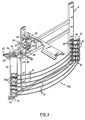
- Figure 5 is a perspective view of the portion of the shaker assembly shown in Figure 3;
- Figure 6 shows how the flexible rods of the shaker assembly act on a fruit tree or bush, for example on a vine plant; and
- Figure 7 is a side elevational view of a shaker rod in accordance with the present invention.
-
- The harvesting machine shown in Figures 1 and 2 is a grape harvester and comprises, in a conventional manner, a
chassis 1 provided with frontsteerable wheels 2 andrear traction wheels 3 for moving thechassis 1 over the ground. Thechassis 1 is in the from of a gantry in order to be able to straddle a row of plants. In known manner, thechassis 1 carries aharvesting assembly 4 comprising ashaker assembly 5 and two elevator conveyors 6 for collecting the grapes that have been detached by theshaker assembly 5 in order to convey them to a temporary storage tank 7 (generally two tanks are provided on respective sides of the machine). The chassis also has anengine 8 providing the rotational power necessary to drive the various active members of the machine and also for providing motive power to the wheels in case the machine is of the self-propelled type. - The
harvesting assembly 4 may be fixed in a permanent manner to thechassis 1 of the machine or else it may be made in the form of a removable assembly which is detachably fixed to thechassis 1 so as to be capable of being replaced by other equipment or accessories, such as spraying equipment, pruning equipment, equipment for tilling the ground, etc. Theharvesting assembly 4 can therefore either be supported directly by thechassis 1 of the machine or else it may be supported by anauxiliary chassis 9. In known manner, theauxiliary chassis 9 may be mounted fixedly relative to thechassis 1 or it may be pivotally mounted thereon with its top portion being pivotally attached to a horizontal, fore-and-aft extending axis for swinging movement therearound. - As can be seen more particularly in Figure 2, the
shaker assembly 5 comprises twosets shaker members 11, with the twosets longitudinal median plane 12 of the machine. As can be seen more clearly in Figure 3, each set, e.g. theset 10a, may comprise sixshaker members 11, for example, which are vertically spaced one above the other and which extend generally horizontally, even though they may also slope downwardly going from the front towards the rear of the machine. Although the shaker assembly shown in Figures 1 to 3 comprise two sets of six shaker members, it is obvious that the number may be decreased or increased depending on types of fruit tree or bush, and for a given type of fruit tree or bush depending on the variety, the way in which it has been trained, and the shape of the vegetation of the fruit trees or bushes. Variations may also depend on whether it is desired to shake the fruit trees or bushes by their trunks or by their vegetation. - Each
shaker member 11 is constituted by a flexible rod whose cross-section is very small compared to its length and as can be seen more particularly in Figures 4 and 5, eachrod 11 is curved to form an arc. The rods used may be pre-curved on manufacture but preferably they are rectilinear, in which case they are curved by bending when mounted on theshaking assembly 5. - With particular reference to Figures 3 to 5, one of the ends of each
rod 11 is firmly clamped in aclamp 13a which is rigidly fixed to a vertical support plate 13 (with oneplate 13 being provided for each of the twosets plate 13 is provided at each of its ends with a verticallyoriented stub axle 14 rotatably received in abearing 15 fixed on theauxiliary chassis 9. The other end of eachrod 11 is fixed in asupport 16 which is hinged about avertical axis 17 at one of the ends of ashort link 18 whose other end is hinged to theauxiliary chassis 9 about avertical axis 19. - A
drive device 20 producing a reciprocating motion is connected to thesupport plate 13 on one of the twosets rods 11 in order to cause theplate 13 to oscillate about the axis of thestub axles 14. Thedrive device 20 may be constituted, for example, by a connecting rod and crank system whoseshaft 21 is rotatable in bearings 22 (as seen in Figures 3 and 5) which are fixed to theauxiliary chassis 9. Theshaft 21 may be rotated by any appropriate transmission (not shown) connected to the output shaft of a motor, for example themotor 8 of the harvesting machine. One of the ends of the connectingrod 24 is hinged to acrank pin 23 of the connecting rod andcrank pin system 20 while its opposite end is hinged about anaxis 25 to ahorizontal arm 26 which is rigidly fixed to thesupport plate 13 for theset 10a ofrods 11. Two otherhorizontal arms 27 extend substantially parallel to the longitudinalmedian plane 12 of the machine and are rigidly fixed to respective ones of the twovertical plates 13. Thearms 27 are interconnected by a horizontal andtransverse coupling rod 28 which ends are hinged to respective ones of the free ends of thearms 27 aboutaxes 29. Preferably, thecoupling rod 28 is in the form of a rod of which the length is adjustable, such as by a turnbuckle as shown in Figure 4, in order to enable the symmetrical adjustment of the twosets rods 11 relative to themedian plane 12 of the machine. - In the following description, it is assumed that the harvesting machine advances in the direction indicated by arrow F in Figure 4. Under such conditions, the
support plates 13 are at the front ends of therods 11, whereas the supports 16 and thelinks 18 are at the rear ends of therods 11, even though the opposite configuration could equally well be used. Under these conditions, going from the front to the rear of the machine, the arcuate shape of theflexible rods 11 in the twosets length 1 as approximately indicated in Figure 4, which in turn is followed by a diverging outlet zone for the fruit trees or bushes. - In Figure 4, letters A, B, C and D indicate the positions taken up by the various components of the shaker assembly for four different angular positions A, B, C and D of the connecting rod and
crank drive system 20. From Figure 4, it is clear that during rotation of thecrank pin 23 about the axis of theshaft 21, the curvature of theflexible rods 11 varies cyclically about an average value of curvature which corresponds to positions A and C and which lies between a minimum curvature and a maximum curvature. It can also be seen that theflexible rods 11 of theset 10a are at minimum curvature when theflexible rods 11 of theset 10b are at maximum curvature (position B), and conversely that therods 11 of theset 10a are at maximum curvature when therods 11 of theset 10b are at minimum curvature (position D). It can also be seen that while therods 11 are bending from their minimum curvature position towards their maximum curvature position, their front and rear ends remain at a substantially constant distance from the longitudinalmedian plane 12, whereas the active shaking zone l reciprocates transversely on either side of saidlongitudinal plane 12. The amplitude of the transverse movement of the active portion of theflexible rods 11 depend on their maximum and minimum values of curvature which in turn depend on the eccentricity of thecrank pin 23 relative to the axis of theshaft 21. Preferably, the eccentricity of thecrank pin 23 is adjustable in known manner in order to make it possible to adjust the amplitude of the transverse motion of the active portion of theflexible rods 11. Preferably, the connectingrod 24 is also provided in the form of a rod of variable length in order to make it possible to adjust the average position (positions A, C) of therods 11 so that the distance e between the active portions of the rods in the twosets - Figure 6 shows how the
flexible rods 11 of the shaker assembly of a harvesting machine in accordance with the present invention are capable of adapting individually to the thickness of thevegetation 30 on a fruit tree or bush such as a vine plant. This may be explained in the following manner. When a vine plant arrives in the converging inlet portion between the twosets rods 11, the vegetation applies forces to therods 11 such that the longitudinal components thereof are transmitted by said rods to thelinks 18 which pivot rearwardly about theiraxes 19. Simultaneously, by virtue of their high degree of flexibility, therods 11 deform elastically (their curvature decreases) and move further and further away from the longitudinalmedian plane 12 depending on the thickness of the vegetation at the height of eachrod 11. Conversely, during shaking in the active shaking zone, the transverse forces applied to therods 11 which are due to the resistance put up by the vegetation against saidrods 11 have a reduced tendency to pivot thelinks 18 rearwardly about theiraxes 19 because thelinks 18 extend roughly transversely relative to the longitudinalmedian plane 12 and are substantially perpendicular to the rear ends of therods 11. Consequently, during shaking, therods 11 deform relatively little by bending and the amplitude of their motion is practically fully transmitted to the vegetation. - Each
shaker member 11 is made of a material which is very flexible and deformable, for example a polyamide or a glass fibre reinforced polyester. In the arrangement shown, good results have been obtained on vines when using solid rods having a circular section with a diameter in the range of 25 to 30 mm and a length of approximately 2 m made of a polyamide 66 type of which the modulus of elasticity E is equal to approximately 3000 N/mm2. With such a configuration, a maximum operating frequency of about 7,2 Hz (i.e. approximately 430 RPM) is obtainable, which is already close to the resonance frequency of ashaker member 11, as such preventing the frequency of thedrive mechanism 20 to be increased above 7,2 Hz in cases where really needed, such as when harvesting under conditions where the grapes or bunches of grapes are difficult to detach from the vines. - In practice, certain types of shaker mechanisms, having semi loop-shaped rods (not shown) for example, already may operate at higher frequencies without going into resonance, which is due to the fact that these rods normally are rather short. It will be appreciated however that as a result thereof, the active shaking zone of such rods is reduced in length, meaning that, for a given driving speed, the operating frequency should be higher in order to obtain a sufficient number of oscillations transmitted to a given bunch of grapes. Increasing the operating frequency any further for increasing the operating efficiency under special harvesting conditions again would be impossible since the rods would go into resonance.
- With specific reference to Figure 7, an
individual rod 11 is shown having a rectilinear shape being the shape before it is mounted on the shakingassembly 5. Therod 11 comprises afront end 32 for being clamped by aclamp 13a and arear end 34 for attachment to asupport 16. In accordance with the present invention, the mass, and therefore the weight, of eachrod 11 is decreased by providing a central cavity therein, preferably in the form of acylindrical bore 36, indicated in Figures 6 and 7, extending longitudinally along the full length of therod 11. The diameter of the bore is in the range of 10 to 20 mm and the bore is provided to reduce the amount of rod material around the central,longitudinal axis 38 of therod 11 considering that said material only adds up to the weight of therod 11 without having any considerable influence on the increase of the rigidity thereof. Reducing the mass of rod material, especially in the region close to thecentral axis 38, presents an important step in increasing the resonance frequency of therod 11. In addition, the outer diameter of therod 11 is slightly increased when compared to a rod with a solid section to a value inbetween 30 and 35 mm in order to render therod 11 more rigid, thereby again having a positive effect on the resonance frequency thereof. As the increase in diameter is only minor, no adverse effects on the operating efficiency of therod 11 are to be feared. As a result of these modifications, the working frequency of therod 11 may be increased to more than 8.8 Hz (approximately 530 RPM) without going into resonance. - At each end of the
rod 11, aplug member 40 is inserted into thebore 36 on the one hand to prevent foreign material such as dust, grape juice, etc to enter and accumulate into thebore 36 whereby the positive effect of thebore 36 on the resonance frequency would be impaired and on the other hand to reinforce theends respective supports plug members 40 may be glued into thebore 36 or fastened in any other convenient manner. Preferably, theplug members 40 are made of material similar to the material of therods 11. - Although with the present arrangement the resonance frequency of the
rods 11 has been increased, it nevertheless may occur that arod 11 inadvertently is ruptured during operation, caused e.g. by the shakingmechanism 5 hitting a solid object located too far out of line with the vines. In case no immediate action is taken to neutralize the drive of the shaking mechanism, a ruptured rod may cause serious damage, not only to the vines, but also to the other rods, which in turn may become ruptured. Since it is a common practice to equip present day grape harvesters with an operator's cab shielding the operator from the environment and hence also from external sounds, it is foreseeable that a ruptured rod will not immediately be noticed by the operator. To prevent this from happening, a thinelectrical wire 42, to which a low voltage is applied, may be run through thebore 36 in eachrod 11, all thesewires 42 being operatively connected together and linked to a warning or control system (not shown) in the operator's cab. Thewires 42 are installed into thebores 36 with some play allowing therods 11 to flex as desired without imparting any damage to thewires 42. As long as all wires are intact, no warning or control signal is generated. However, it will be appreciated that upon rupture of arod 11, the associatedwire 42 also will be snapped, whereby the operator receives an audible or visual alarm signal in his cab enabling him to take immediate action or a control signal may be generated whereby the drive to the shaking mechanism is immediately disengaged. - It will be appreciated that the
bore 36 should not necessarily extend along the full length of therod 11, but may stop short of the opposite ends of therod 11 whereby theplug members 40 are no longer needed. In still other embodiments, therod 11 may comprise several individual, spherical or oblong cavities, all aiming to reduce the weight of the rod. Considering that, as best seen in Figure 4, therods 11 are always curved and pretensioned in a given direction, thebore 36 or individual cavities may be provided eccentrically of thecentral axis 38, preferably offset in the direction of the inward curve or concave side of therod 11 since the rod material at this location has the least influence on the rigidity of therod 11. In extremis, thebore 36 may have an irregular cross-sectional shape and may even pierce through the longitudinal side of therod 11, whereby the bore no longer would be provided fully internally of therod 11. Still further, instead of rods with a circular cross section, also oval shaped, hollow rods may be employed. A prerequisite of all the above embodiments is to provide the bores or cavities in a region of the rods having only little influence on the rigidity thereof in such a manner that the ratio of the rigidity reduction versus weight reduction is increased leading to higher resonance frequencies. - Although the present invention has been described with reference to a
shaking mechanism 5 in which the front ends 32 of theshaker rods 11 are fixedly attached to anoscillating drive mechanism 13 while the rear ends 34 are pivotally connected to alink mechanism 18, it will be clear that the invention is applicable to all kinds of shaker or beater mechanisms employing flexible rods. As an example, the rods may be attached at one end only while the opposite end is free to move and constitutes the active portion of the rod.
Claims (9)
- A machine for harvesting fruits, berries and the like, from fruit trees and bushes planted in rows, the machine comprising :a straddling chassis (1) capable of moving across a field;a shaker assembly (5), mounted on the chassis (1) and including at least one pair (10a, 10b) of elongated shaker members (11) which extend generally in the longitudinal direction of the machine and which are spaced transversely from one another and situated respectively on opposite sides of the central fore-and-aft axis (12) of the machine so as to define an active shaking zone (1), each shaker member being formed by a rod (11) of flexible material; anda control mechanism (20) operatively connected to the rods (11) to drive them synchronously with a reciprocating motion in a direction extending transversely relative to said fore-and-aft axis (12); and
characterized in that each rod (11) comprises at least one cavity (36) to reduce the weight thereof. - A machine according to claim 1 characterized in that the at least one cavity (36) is provided internally of the rod (11).
- A machine according to claims 1 or 2 characterized in that the at least one cavity (36) takes the form of a cylindrical bore (36) extending in the longitudinal direction of the rod (11).
- A machine according to claim 3 characterized in that the bore (36) is provided coaxially with the longitudinal axis (38) of the rod (11).
- A machine according to claims 3 or 4 characterized in that the bore (36) extends the full length of the rod (11).
- A machine according to claim 5 characterized in that the opposite ends (32, 34) of the rod (11) are closed by plug members (40).
- A machine according to any of the claims 3 to 6 characterized in that conductive wire means (42) are provided in the bore (36); said wire means (42) being connected to a warning system or a control system in a manner such that, upon rupture of a rod (11) and the associated wire means (42), the operator is warned and/or the drive to the shaker assembly (5) is automatically disengaged.
- A machine according to any of the preceding claims characterized in that each flexible rod (11) has one of its ends articulated to a fixed point (14) on the chassis (1) and its opposite end attached to a point (17) which can move in a direction substantially parallel to the central fore-and-aft axis (12) of the machine.
- A machine according to any of the claims 1 to 7 characterized in that each flexible rod (11) has one of its ends articulated to a fixed point (14) on the chassis (1) while its opposite end is free to move in a direction substantially perpendicular to the central fore-and-aft axis (12) of the machine.
Applications Claiming Priority (2)
| Application Number | Priority Date | Filing Date | Title |
|---|---|---|---|
| GB9414004 | 1994-07-12 | ||
| GB9414004A GB2291330A (en) | 1994-07-12 | 1994-07-12 | Shaking fruit from plants |
Publications (2)
| Publication Number | Publication Date |
|---|---|
| EP0692181A1 EP0692181A1 (en) | 1996-01-17 |
| EP0692181B1 true EP0692181B1 (en) | 1999-09-29 |
Family
ID=10758178
Family Applications (1)
| Application Number | Title | Priority Date | Filing Date |
|---|---|---|---|
| EP95201900A Expired - Lifetime EP0692181B1 (en) | 1994-07-12 | 1995-07-11 | Shaker members for grape harvester |
Country Status (6)
| Country | Link |
|---|---|
| US (1) | US5642610A (en) |
| EP (1) | EP0692181B1 (en) |
| DE (1) | DE69512474T2 (en) |
| ES (1) | ES2137445T3 (en) |
| GB (1) | GB2291330A (en) |
| NZ (1) | NZ272452A (en) |
Families Citing this family (22)
| Publication number | Priority date | Publication date | Assignee | Title |
|---|---|---|---|---|
| AUPO029796A0 (en) * | 1996-06-07 | 1996-07-04 | Jarmain, Paul Laurence | Grape harvester improvements |
| FR2752940A1 (en) * | 1996-08-30 | 1998-03-06 | Cemagref | METHOD AND DEVICE FOR DETERMINING A PROPORTION BETWEEN FRUITS AND FOREIGN BODIES AND METHOD AND MACHINE FOR HARVESTING FRUITS |
| FR2768016B1 (en) * | 1997-09-05 | 1999-10-08 | Pellenc Sa | SELECTIVE BERRY HARVESTING MACHINE AND METHOD |
| FR2789262B1 (en) | 1999-02-05 | 2001-04-06 | New Holland Braud Sa | MACHINE FOR HARVESTING FRUITS, BERRIES AND THE LIKE CARRIED BY FRUIT TREES AND SHRUBS PLANTS IN LINE, AND SHAKING ROD FOR SUCH A MACHINE |
| FR2813493A1 (en) * | 2000-09-05 | 2002-03-08 | New Holland Braud Sa | HARVESTING DEVICE WITH DETACHABLE SHAKERS FOR FRUIT, BERRY AND THE LIKE HARVESTING MACHINE |
| US6442920B1 (en) * | 2001-06-07 | 2002-09-03 | The United States Of America As Represented By The Secretary Of Agriculture | Mechanical harvester for tree fruits |
| KR20020097387A (en) * | 2001-06-20 | 2002-12-31 | 대한민국(충남대학교) | Boxthorn Harvester |
| US6634162B1 (en) * | 2002-06-17 | 2003-10-21 | Matt Andros | Simultaneous processing of multiple rows of plants, especially trellised rows |
| FR2855366B1 (en) * | 2003-05-27 | 2005-07-15 | Cnh France Sa | HARVESTING DEVICE WITH FLEXIBLE RODS FOR MACHINE FOR HARVESTING FRUITS, BERRIES AND THE LIKE |
| FR2921539B1 (en) * | 2007-09-28 | 2011-08-19 | Pellenc Sa | ALLEGED VIBRATION PLIERS FOR DRY FRUIT RECOVERY MACHINES. |
| FR2934458B1 (en) * | 2008-08-01 | 2010-09-03 | Pellenc Sa | BERRIES HARVESTING MACHINE, ESPECIALLY A SINGLE MACHINE WITH A DRYING SYSTEM, AND A MECATRONIC SECONDARY CONTROL OF THIS SYSTEM. |
| US7748206B1 (en) * | 2009-03-10 | 2010-07-06 | Cnh America Llc | Fruit harvester with system and method for detecting and reducing forces exerted against rigid standing objects |
| FR2971668B1 (en) * | 2011-02-22 | 2014-02-28 | Cnh France | FRUIT HARVESTING UNIT AND HARVESTING MACHINE ON WHICH SUCH UNIT IS INTENDED TO BE MOUNTED |
| NL2009207C2 (en) * | 2012-07-19 | 2013-05-01 | Driessen Blueberries B V | DEVICE SUITABLE FOR HARVESTING FRUIT PENDING ON A PLANT AND A METHOD FOR HARVESTING HARVESTING FRUIT PENDING ON A PLANT. |
| ES2523036B1 (en) * | 2013-05-20 | 2015-09-08 | Francisco MORENO MARTÍNEZ | Fruit harvester |
| US9832929B1 (en) * | 2013-11-05 | 2017-12-05 | William Majors | Harvesting head and machine for mechanically harvesting olives, grapes and the like |
| WO2016033020A1 (en) | 2014-08-26 | 2016-03-03 | The Wine Group | Conversion of harvester picking head |
| TWI571198B (en) * | 2014-10-13 | 2017-02-21 | Castor fruit harvesting device, harvesting machine and harvesting method | |
| US20170238465A1 (en) * | 2015-09-29 | 2017-08-24 | Ronald Edward Bodtke | Blueberry harvester and method of harvesting |
| CN105519306B (en) * | 2015-12-22 | 2018-03-27 | 马树民 | The picking method and its device of a kind of medlar fresh fruit |
| US10045484B2 (en) * | 2016-02-12 | 2018-08-14 | A & B Packing Equipment, Inc. | Shaped conveyor system for a harvester |
| US20250031622A1 (en) * | 2023-07-27 | 2025-01-30 | Brian Andersen | Autonomously guided, continuous movement harvester |
Family Cites Families (8)
| Publication number | Priority date | Publication date | Assignee | Title |
|---|---|---|---|---|
| US4016711A (en) * | 1975-06-09 | 1977-04-12 | Up-Right, Inc. | Vine-fruit harvesting machine with inclined-tip striker rods |
| US4016712A (en) * | 1976-02-25 | 1977-04-12 | Hesston Corporation | Machine for forming high density round bales |
| US4336682A (en) * | 1980-08-15 | 1982-06-29 | Fmc Corporation | Continuous harvester for plants grown in rows |
| US4418521A (en) * | 1981-12-11 | 1983-12-06 | Fmc Corporation | Harvester with selective force balanced shaking mechanism |
| FR2605487B1 (en) * | 1986-10-27 | 1989-03-31 | Braud Sa | MACHINE FOR HARVESTING FRUITS, BERRIES AND THE LIKE CARRIED BY FRUIT TREES AND SHRUBS PLANTS ONLINE |
| FR2605488B1 (en) * | 1986-10-27 | 1989-03-31 | Braud Sa | MACHINE FOR HARVESTING FRUITS, BERRIES AND THE LIKE CARRIED BY FRUIT TREES AND SHRUBS PLANTS ONLINE |
| FR2641158A1 (en) * | 1988-12-29 | 1990-07-06 | Lignones Hubert | Shaking device for a machine for harvesting berries |
| NZ240461A (en) * | 1991-11-04 | 1994-12-22 | Donald John Nairn | U-shaped shaker rod for grape or fruit harvester: rod constructed in two parts having different rigidities |
-
1994
- 1994-07-12 GB GB9414004A patent/GB2291330A/en not_active Withdrawn
-
1995
- 1995-06-27 NZ NZ272452A patent/NZ272452A/en not_active IP Right Cessation
- 1995-07-11 EP EP95201900A patent/EP0692181B1/en not_active Expired - Lifetime
- 1995-07-11 DE DE69512474T patent/DE69512474T2/en not_active Expired - Lifetime
- 1995-07-11 ES ES95201900T patent/ES2137445T3/en not_active Expired - Lifetime
- 1995-07-12 US US08/501,693 patent/US5642610A/en not_active Expired - Lifetime
Also Published As
| Publication number | Publication date |
|---|---|
| US5642610A (en) | 1997-07-01 |
| DE69512474D1 (en) | 1999-11-04 |
| NZ272452A (en) | 1997-09-22 |
| DE69512474T2 (en) | 2000-02-03 |
| ES2137445T3 (en) | 1999-12-16 |
| EP0692181A1 (en) | 1996-01-17 |
| GB2291330A (en) | 1996-01-24 |
| GB9414004D0 (en) | 1994-08-31 |
Similar Documents
| Publication | Publication Date | Title |
|---|---|---|
| US5642610A (en) | Shaker members for grape harvester | |
| US4769979A (en) | Machine for harvesting fruit and berries and the like, from fruit trees and bushes planted in a row | |
| US4771594A (en) | Machine for harvesting fruit and berries and the like, from fruit trees and bushes planted in a row | |
| US4336682A (en) | Continuous harvester for plants grown in rows | |
| US4418521A (en) | Harvester with selective force balanced shaking mechanism | |
| US5904034A (en) | Tree borne fruit harvester | |
| US4286426A (en) | Vibratory fruit harvester | |
| US8511051B2 (en) | Berry harvesting machine, especially grape harvesting machine, equipped with a shaking system and mechatronic shaking control for this system | |
| AU2009203190B2 (en) | Shaker with adjustable stiffness for harvesting machines and harvesting machines using such shakers | |
| CA1258979A (en) | Apparatus and methods for dislodging and collecting produce from upstanding crops | |
| US4974404A (en) | Apparatus and method for adjusting a harvester to an oblique profile of cane type berry plants | |
| EP1148775B1 (en) | Machine for harvesting fruit and berries and the like from fruit trees and bushes planted in a row, and shaker rod for a machine of this kind | |
| US4329836A (en) | Harvesting units | |
| US8069641B2 (en) | Harvesting machine for small fruit produced in orchards | |
| US4793128A (en) | Horizontal force balanced shaker and method | |
| US4014160A (en) | Foliage agitating means for harvesting machines | |
| US4435950A (en) | Fruit or berry harvesting device for in-line crops | |
| US20050034441A1 (en) | Olive harvesting machine | |
| US4959950A (en) | Harvester for grapes | |
| US5421149A (en) | Eccentric oscillating system | |
| EP0010203B1 (en) | Mechanical shaker assembly for continuous harvesting of fruit | |
| US3485027A (en) | Vibratory harvesting machine | |
| CA1200982A (en) | Mechanical berry harvester having row-width- adjustable beater | |
| CN116034719A (en) | A header structure and a soybean combine harvester | |
| US4561241A (en) | Method and harvester attachment for stabilizing grapevines during harvesting |
Legal Events
| Date | Code | Title | Description |
|---|---|---|---|
| PUAI | Public reference made under article 153(3) epc to a published international application that has entered the european phase |
Free format text: ORIGINAL CODE: 0009012 |
|
| AK | Designated contracting states |
Kind code of ref document: A1 Designated state(s): DE ES FR GB IT |
|
| 17P | Request for examination filed |
Effective date: 19960701 |
|
| EL | Fr: translation of claims filed | ||
| GRAG | Despatch of communication of intention to grant |
Free format text: ORIGINAL CODE: EPIDOS AGRA |
|
| 17Q | First examination report despatched |
Effective date: 19980805 |
|
| GRAG | Despatch of communication of intention to grant |
Free format text: ORIGINAL CODE: EPIDOS AGRA |
|
| GRAH | Despatch of communication of intention to grant a patent |
Free format text: ORIGINAL CODE: EPIDOS IGRA |
|
| GRAH | Despatch of communication of intention to grant a patent |
Free format text: ORIGINAL CODE: EPIDOS IGRA |
|
| RAP1 | Party data changed (applicant data changed or rights of an application transferred) |
Owner name: NEW HOLLAND BRAUD S.A. |
|
| GRAA | (expected) grant |
Free format text: ORIGINAL CODE: 0009210 |
|
| AK | Designated contracting states |
Kind code of ref document: B1 Designated state(s): DE ES FR GB IT |
|
| REF | Corresponds to: |
Ref document number: 69512474 Country of ref document: DE Date of ref document: 19991104 |
|
| ET | Fr: translation filed | ||
| REG | Reference to a national code |
Ref country code: ES Ref legal event code: FG2A Ref document number: 2137445 Country of ref document: ES Kind code of ref document: T3 |
|
| ITF | It: translation for a ep patent filed | ||
| PLBE | No opposition filed within time limit |
Free format text: ORIGINAL CODE: 0009261 |
|
| STAA | Information on the status of an ep patent application or granted ep patent |
Free format text: STATUS: NO OPPOSITION FILED WITHIN TIME LIMIT |
|
| 26N | No opposition filed | ||
| REG | Reference to a national code |
Ref country code: GB Ref legal event code: IF02 |
|
| PGFP | Annual fee paid to national office [announced via postgrant information from national office to epo] |
Ref country code: GB Payment date: 20080704 Year of fee payment: 14 |
|
| GBPC | Gb: european patent ceased through non-payment of renewal fee |
Effective date: 20090711 |
|
| PG25 | Lapsed in a contracting state [announced via postgrant information from national office to epo] |
Ref country code: GB Free format text: LAPSE BECAUSE OF NON-PAYMENT OF DUE FEES Effective date: 20090711 |
|
| PGFP | Annual fee paid to national office [announced via postgrant information from national office to epo] |
Ref country code: ES Payment date: 20130704 Year of fee payment: 19 Ref country code: DE Payment date: 20130709 Year of fee payment: 19 |
|
| PGFP | Annual fee paid to national office [announced via postgrant information from national office to epo] |
Ref country code: FR Payment date: 20130730 Year of fee payment: 19 |
|
| PGFP | Annual fee paid to national office [announced via postgrant information from national office to epo] |
Ref country code: IT Payment date: 20130724 Year of fee payment: 19 |
|
| REG | Reference to a national code |
Ref country code: DE Ref legal event code: R119 Ref document number: 69512474 Country of ref document: DE |
|
| REG | Reference to a national code |
Ref country code: FR Ref legal event code: ST Effective date: 20150331 |
|
| PG25 | Lapsed in a contracting state [announced via postgrant information from national office to epo] |
Ref country code: DE Free format text: LAPSE BECAUSE OF NON-PAYMENT OF DUE FEES Effective date: 20150203 Ref country code: IT Free format text: LAPSE BECAUSE OF NON-PAYMENT OF DUE FEES Effective date: 20140711 |
|
| REG | Reference to a national code |
Ref country code: DE Ref legal event code: R119 Ref document number: 69512474 Country of ref document: DE Effective date: 20150203 |
|
| PG25 | Lapsed in a contracting state [announced via postgrant information from national office to epo] |
Ref country code: FR Free format text: LAPSE BECAUSE OF NON-PAYMENT OF DUE FEES Effective date: 20140731 |
|
| REG | Reference to a national code |
Ref country code: ES Ref legal event code: FD2A Effective date: 20150828 |
|
| PG25 | Lapsed in a contracting state [announced via postgrant information from national office to epo] |
Ref country code: ES Free format text: LAPSE BECAUSE OF NON-PAYMENT OF DUE FEES Effective date: 20140712 |