EP0691699A1 - Graphite layer material - Google Patents
Graphite layer material Download PDFInfo
- Publication number
- EP0691699A1 EP0691699A1 EP95110464A EP95110464A EP0691699A1 EP 0691699 A1 EP0691699 A1 EP 0691699A1 EP 95110464 A EP95110464 A EP 95110464A EP 95110464 A EP95110464 A EP 95110464A EP 0691699 A1 EP0691699 A1 EP 0691699A1
- Authority
- EP
- European Patent Office
- Prior art keywords
- graphite
- layer material
- intercalant
- graphite layer
- layers
- Prior art date
- Legal status (The legal status is an assumption and is not a legal conclusion. Google has not performed a legal analysis and makes no representation as to the accuracy of the status listed.)
- Granted
Links
Images

Classifications
-
- H—ELECTRICITY
- H01—ELECTRIC ELEMENTS
- H01M—PROCESSES OR MEANS, e.g. BATTERIES, FOR THE DIRECT CONVERSION OF CHEMICAL ENERGY INTO ELECTRICAL ENERGY
- H01M4/00—Electrodes
- H01M4/02—Electrodes composed of, or comprising, active material
- H01M4/36—Selection of substances as active materials, active masses, active liquids
- H01M4/58—Selection of substances as active materials, active masses, active liquids of inorganic compounds other than oxides or hydroxides, e.g. sulfides, selenides, tellurides, halogenides or LiCoFy; of polyanionic structures, e.g. phosphates, silicates or borates
- H01M4/583—Carbonaceous material, e.g. graphite-intercalation compounds or CFx
- H01M4/587—Carbonaceous material, e.g. graphite-intercalation compounds or CFx for inserting or intercalating light metals
-
- H—ELECTRICITY
- H01—ELECTRIC ELEMENTS
- H01M—PROCESSES OR MEANS, e.g. BATTERIES, FOR THE DIRECT CONVERSION OF CHEMICAL ENERGY INTO ELECTRICAL ENERGY
- H01M10/00—Secondary cells; Manufacture thereof
- H01M10/05—Accumulators with non-aqueous electrolyte
- H01M10/052—Li-accumulators
- H01M10/0525—Rocking-chair batteries, i.e. batteries with lithium insertion or intercalation in both electrodes; Lithium-ion batteries
-
- H—ELECTRICITY
- H01—ELECTRIC ELEMENTS
- H01M—PROCESSES OR MEANS, e.g. BATTERIES, FOR THE DIRECT CONVERSION OF CHEMICAL ENERGY INTO ELECTRICAL ENERGY
- H01M4/00—Electrodes
- H01M4/02—Electrodes composed of, or comprising, active material
- H01M4/13—Electrodes for accumulators with non-aqueous electrolyte, e.g. for lithium-accumulators; Processes of manufacture thereof
- H01M4/133—Electrodes based on carbonaceous material, e.g. graphite-intercalation compounds or CFx
-
- H—ELECTRICITY
- H01—ELECTRIC ELEMENTS
- H01M—PROCESSES OR MEANS, e.g. BATTERIES, FOR THE DIRECT CONVERSION OF CHEMICAL ENERGY INTO ELECTRICAL ENERGY
- H01M4/00—Electrodes
- H01M4/02—Electrodes composed of, or comprising, active material
- H01M4/36—Selection of substances as active materials, active masses, active liquids
- H01M4/58—Selection of substances as active materials, active masses, active liquids of inorganic compounds other than oxides or hydroxides, e.g. sulfides, selenides, tellurides, halogenides or LiCoFy; of polyanionic structures, e.g. phosphates, silicates or borates
- H01M4/583—Carbonaceous material, e.g. graphite-intercalation compounds or CFx
-
- H—ELECTRICITY
- H01—ELECTRIC ELEMENTS
- H01M—PROCESSES OR MEANS, e.g. BATTERIES, FOR THE DIRECT CONVERSION OF CHEMICAL ENERGY INTO ELECTRICAL ENERGY
- H01M10/00—Secondary cells; Manufacture thereof
- H01M10/05—Accumulators with non-aqueous electrolyte
- H01M10/052—Li-accumulators
-
- H—ELECTRICITY
- H01—ELECTRIC ELEMENTS
- H01M—PROCESSES OR MEANS, e.g. BATTERIES, FOR THE DIRECT CONVERSION OF CHEMICAL ENERGY INTO ELECTRICAL ENERGY
- H01M4/00—Electrodes
- H01M4/02—Electrodes composed of, or comprising, active material
- H01M2004/021—Physical characteristics, e.g. porosity, surface area
-
- Y—GENERAL TAGGING OF NEW TECHNOLOGICAL DEVELOPMENTS; GENERAL TAGGING OF CROSS-SECTIONAL TECHNOLOGIES SPANNING OVER SEVERAL SECTIONS OF THE IPC; TECHNICAL SUBJECTS COVERED BY FORMER USPC CROSS-REFERENCE ART COLLECTIONS [XRACs] AND DIGESTS
- Y02—TECHNOLOGIES OR APPLICATIONS FOR MITIGATION OR ADAPTATION AGAINST CLIMATE CHANGE
- Y02E—REDUCTION OF GREENHOUSE GAS [GHG] EMISSIONS, RELATED TO ENERGY GENERATION, TRANSMISSION OR DISTRIBUTION
- Y02E60/00—Enabling technologies; Technologies with a potential or indirect contribution to GHG emissions mitigation
- Y02E60/10—Energy storage using batteries
-
- Y—GENERAL TAGGING OF NEW TECHNOLOGICAL DEVELOPMENTS; GENERAL TAGGING OF CROSS-SECTIONAL TECHNOLOGIES SPANNING OVER SEVERAL SECTIONS OF THE IPC; TECHNICAL SUBJECTS COVERED BY FORMER USPC CROSS-REFERENCE ART COLLECTIONS [XRACs] AND DIGESTS
- Y10—TECHNICAL SUBJECTS COVERED BY FORMER USPC
- Y10T—TECHNICAL SUBJECTS COVERED BY FORMER US CLASSIFICATION
- Y10T428/00—Stock material or miscellaneous articles
- Y10T428/249921—Web or sheet containing structurally defined element or component
- Y10T428/249953—Composite having voids in a component [e.g., porous, cellular, etc.]
- Y10T428/249967—Inorganic matrix in void-containing component
-
- Y—GENERAL TAGGING OF NEW TECHNOLOGICAL DEVELOPMENTS; GENERAL TAGGING OF CROSS-SECTIONAL TECHNOLOGIES SPANNING OVER SEVERAL SECTIONS OF THE IPC; TECHNICAL SUBJECTS COVERED BY FORMER USPC CROSS-REFERENCE ART COLLECTIONS [XRACs] AND DIGESTS
- Y10—TECHNICAL SUBJECTS COVERED BY FORMER USPC
- Y10T—TECHNICAL SUBJECTS COVERED BY FORMER US CLASSIFICATION
- Y10T428/00—Stock material or miscellaneous articles
- Y10T428/249921—Web or sheet containing structurally defined element or component
- Y10T428/249953—Composite having voids in a component [e.g., porous, cellular, etc.]
- Y10T428/249978—Voids specified as micro
-
- Y—GENERAL TAGGING OF NEW TECHNOLOGICAL DEVELOPMENTS; GENERAL TAGGING OF CROSS-SECTIONAL TECHNOLOGIES SPANNING OVER SEVERAL SECTIONS OF THE IPC; TECHNICAL SUBJECTS COVERED BY FORMER USPC CROSS-REFERENCE ART COLLECTIONS [XRACs] AND DIGESTS
- Y10—TECHNICAL SUBJECTS COVERED BY FORMER USPC
- Y10T—TECHNICAL SUBJECTS COVERED BY FORMER US CLASSIFICATION
- Y10T428/00—Stock material or miscellaneous articles
- Y10T428/30—Self-sustaining carbon mass or layer with impregnant or other layer
Definitions
- the present invention relates to a graphite layer material. More particularly, it relates to a graphite layer material which is used for a graphite electrode for a secondary cell.
- Graphites are important as industrial materials because of their useful characteristics such as excellent heat and chemical resistances, high conductivity, etc., and have been widely used as electrode materials for secondary cells, heating elements, structural materials, gaskets, heat resistant sealing materials and the like.
- Examples of the conventional graphite to be used for these applications include the followings.
- the electrode for secondary cell using the graphite or carbon is used by bringing lithium into contact with the graphite, forming an interlayer compound which is obtained by inserting lithium between layers of the graphite to cause dedoping/doping to take electric current out.
- the cell characteristics are largely influenced by the properties of the graphite or carbon electrode, and are not always good.
- Highly oriented graphite has recently been studied as novel graphite.
- One of them is a so-called "HOPG (Highly Oriented Pyrolytic Graphite)" which is obtained by depositing carbon atom on a substrate using a hydrocarbon gas by a CVD (Chemical Vapor Deposition) process, followed by annealing.
- the HOPG is one in which the orientation direction of a crystal is adjusted to one direction.
- Another highly oriented pyrogenic graphite which is obtained by a different production process is described in Japanese Laid-Open Patent Publication Nos. 3-75211, 4-21508, etc.
- the graphites can be produced in a short time and has a desired size and excellent physical properties approaching those of a homogeneous single crystal, which arises no problem due to the residual acid described in the above item (b).
- the cell characteristics are largely influenced by the properties of the graphite or carbon electrode, and the cell is not superior in cell characteristics.
- One object of the present invention is to provide a graphite layer material, comprising a highly oriented graphite and an intercalant, the intercalant being inserted between layers of the highly oriented graphite, which is used as an electrode material exhibiting excellent cell characteristics when used for a secondary cell.
- Another object of the present invention is to provide a graphite layer material which exhibits excellent cell characteristics when used for a secondary cell, by inserting an intercalant between layers of a highly oriented graphite, rapidly and uniformly, to control an amount of the intercalant to be inserted.
- Fig. 1 is a sectional view illustrating a lithium secondary cell using the graphite layer material of one embodiment of the present invention as a graphite electrode material for secondary cell.
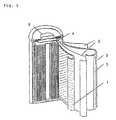
- Fig. 2 is a sectional view illustrating a lithium secondary cell using the graphite layer material of another embodiment of the present invention as a graphite electrode material for secondary cell.
- the present inventors have studied intensively in order to solve the above mentioned problems. It has been found that preferred characteristics can be obtained when using a highly oriented graphite of which a direction of crystalline orientation is adjusted to a planar direction as the graphite. It has also been found that, when an intercalant is inserted between the highly oriented graphite layers, most of the intercalant is inserted in the direction parallel to the direction of crystalline orientation through an interlayer gap at an end surface of the graphite, and strong carbon skeleton disturbs the insertion of the intercalant from the direction perpendicular to the direction of crystalline orientation.
- the present invention provides a graphite layer material which comprises highly oriented graphite layers of which a direction of crystalline orientation is adjusted to a planar direction, and an intercalant inserted between the graphite layers.
- the graphite layer material of the present invention is characterized in that an intercalant is inserted between highly oriented graphite layer of which a direction of crystalline orientation is adjusted to a planar direction.
- the intercalant to be used is preferably a donative intercalant, more preferably at least one selected from the group consisting of chloride and fluoride.
- the highly oriented graphite layer material is provided with a large number of micropores.
- the highly oriented graphite layer material is that obtained by graphitizing polymer film.
- Preferred polymer film is made from at least one selected from the group consisting of polyoxadiazole, polybenzothiazole, polybenzobisthiazole, polybenzoxazole, polybenzobisoxazole, polyimide, polyamide, polyphenylenebenzoimidazole, polyphenylenebenzimidazole, polythiazole and polyparaphenylenevinylene.
- the graphitization is conducted by calcining at a temperature of not less than 2000 °C.
- the highly oriented graphite planar material has a flexibility.
- Preferred intercalant is at least one selected from the group consisting of Li, K, Rb, Cs, Sr and Ba.
- a size of the micropore is 1 to 100 ⁇ m.
- the highly oriented graphite layer material to be used for the graphite layer material of the present invention may be one that a direction of crystalline orientation is adjusted to a planar direction.
- Examples thereof include one which is obtained by depositing carbon atom on a substrate by a CVD process using a hydrocarbon gas, followed by annealing; one which is obtained by graphitizing polymer film; and the like.
- one which is obtained by graphitizing polymer film is preferably used because the intercalant can be inserted between the resulting graphite layers, rapidly and uniformly.
- polymer film made from at least one selected from the group consisting of polyoxadiazoles (POD), polybenzothiazole (PBT), polybenzobisthiazole (PBBT), polybenzoxazole (PBO), polybenzobisoxazole (PBBO), polyimides (PI), polyamides (PA), polyphenylenebenzimidazole (PBI), polyphenylenebenzbisimidazole (PPBI), polythiazole (PT) and polyparaphenylenevinylene (PPV), because the intercalant can be inserted between the resulting graphite layers, rapidly and uniformly.
- POD polyoxadiazoles
- PBT polybenzothiazole
- PBBT polybenzobisthiazole
- PBO polybenzoxazole
- PBBO polybenzobisoxazole
- PI polyimides
- PA polyamides
- PA polyphenylenebenzimidazole
- PPBI polyphenylenebenzbisimidazole
- PT polythiazo
- Polyoxadiazoles include polyparaphenylene-1,3,4-oxadiazole and an isomer thereof.
- the calcining condition for graphitizing the polymer film is not specifically limited, but preferably at a temperature of not less than 2000 °C, more preferably about 3000 °C because the intercalant can be inserted between the resulting graphite layers, rapidly and uniformly.
- the calcining is normally conducted in an inert gas.
- a thickness of the polymer film is preferably not less than 100 ⁇ m, in order to inhibit influence of a gas to be generated in the process of the graphitization by adjusting a treating atmosphere to a pressure atmosphere at the time of calcining.
- the pressure at the time of calcining varies depending upon a film thickness, but is preferably within a range of 0.1 to 50 kg/cm2.
- a sheeting treatment may be optionally conducted.
- the polymer film is graphitized ,for example, by a process comprising cutting the polymer film into pieces having a suitable size, introducing one cut film or a laminate of about 1000 cut films in a calcining furnace, heating to 3000 °C to graphitize the film or laminate. After calcining, the graphitized film or laminate may be optionally subjected to a sheeting treatment, as described above.
- the highly oriented graphite planar material thus obtained may take any form such as film, sheet, plate and the like. Further, it may be flexible or hard with no flexibility.
- the highly oriented graphite layer material having a flexibility is preferred so as to use the graphite layer material of the present invention as the electrode material in an integrated form.
- a thickness of the polymer film is preferably within a range of not more than 400 ⁇ m, more preferably 5 to 200 ⁇ m.
- the thickness of the raw film exceeds 400 ⁇ m, the film changes into a degradated state by a gas to be generated from the interior of film in the heat treatment process. Therefore, it becomes difficult to use it alone as a good quality electrode material.
- the graphite in the degradated state can be an useful electrode material if it is molded into a composite material with a fluorine resin such as polytetrafluoroethylene known to so-called "Teflon". Further, it is also possible to use the graphite by making it powder to mold into a composite material with a fluorine resin. In case of composite material, the proportion (weight ratio) of the graphite to the fluorine resin is preferably within a range of 50:1 to 2:1.
- the intercalant a donative one is suitable and is preferred as the electrode for secondary cell. It is more preferred that the intercalant is at least one selected from the group consisting of chloride and fluoride.
- chloride and fluoride there can be used chlorides and fluorides of any metal.
- the graphite layer material becomes an electrode material exhibiting excellent cell characteristics when used for a secondary cell.
- Interlayer compounds having a different layer structure can be obtained from the same intercalant substance depending on reaction condition.
- the interlayer compound is formed by an interaction between a guest substance (intercalant) inserted between graphite layers as a host.
- the highly oriented graphite layer material is processed so that it may have many micropores on its surface.
- the intercalant can be inserted between the graphite layers, rapidly and uniformly, to control the amount of the intercalant to be inserted, thereby exhibiting excellent cell characteristics when using the graphite layer material for the secondary cell.
- the method for perforating the micropores on the surface of the layer material is not specifically limited, for example,the micropores may be perforated by subjecting to perforation processing using a press, or the micropores may be perforated using laser beam.
- the shape of the micropores is not specifically limited, and it takes any form such as circle, ellipse, polygon and the like.
- the size of the micropore is not specifically limited, for example, it is 1 to 100 ⁇ m. When the size is within this range, it becomes possible to insert the intercalant between layers of the highly oriented graphite, more rapidly and uniformly, to precisely control the amount of the intercalant to be inserted.
- the size of the micropore is preferably 2 to 50 ⁇ m, more preferably 5 to 20 ⁇ m.
- a large number of micropores may be arranged on the surface of the layer material, regularly or irregularly. However, it is preferred that micropores are arranged regularly in order to insert the intercalant between the graphite layers, uniformly, to control the amount of the intercalant to be inserted.
- the method for inserting the intercalant between the graphite layers through a large number of micropores on the surface of the highly oriented graphite layer material is not specifically limited, and examples thereof include vapor phase constant pressure reaction process, liquid phase contact process, solid phase pressure process, solvent process and the like.
- the intercalant is diffused between the graphite layers by an action such as capillary action through a large number of micropores on the surface of the highly oriented graphite layer material.
- the intercalant can be inserted between the graphite layers, rapidly and uniformly, to control the amount of the intercalant to be inserted.
- a strong carbon skeleton does not disturb the insertion of the intercalant from the direction perpendicular to the direction of crystalline orientation and, therefore, the intercalant can be inserted between layers of the graphite from the direction perpendicular to the orientation of the crystal through a large number of micropores. Not only the intercalant is inserted between layers through a large number of micropores, but also it is sometimes inserted in the direction parallel to the orientation direction of the crystal through an interlayer gap between layers at the end surface of the graphite.
- the graphite layer material obtained by inserting the intercalant between graphite layers of the highly oriented graphite planar material thus obtained may be subjected to a dedoping treatment.
- the method for conducting the dedoping process is not specifically limited, for example, there can be used a method for conducting a heat treatment by washing with water or water vapor at elevated temperature.
- the graphite interlayer compound changes into the state where the interaction between layers is deteriorated by subjecting to the dedoping treatment, and excellent cell characteristics can be exhibited when using the graphite layer material as a cell material.
- the graphite layer material obtained according to the present invention is preferably used as an electrode material of a positive electrode of the secondary cell using lithium as a negative electrode, particularly.
- the graphite layer material of the present invention can exhibit doping and dedoping actions, thereby exhibiting excellent cell characteristics, because the intercalant is inserted between layers of the highly oriented graphite layer material of which a direction of crystalline orientation is adjusted to a planar direction.
- the intercalant can be inserted between layers through these micropores.
- the graphite layer material of the present invention can be used as an electrode material exhibiting excellent cell characteristics when using for a secondary cell, because it comprises a highly oriented graphite layer material of which a direction of crystalline orientation is adjusted to a planar direction, and an intercalant inserted between the graphite layers.
- the intercalant can be preferably used as an electrode for secondary cell when the intercalant is a donative intercalant. It is more preferred that the intercalant is at least one sort selected from the group consisting of chloride and fluoride.
- the highly oriented graphite planar material is provided with a large number of micropores
- a graphite layer material exhibiting excellent cell characteristics when using for a secondary cell, by inserting an intercalant between layers of the highly oriented graphite, rapidly and uniformly, to control the amount of the intercalant to be inserted.
- the highly oriented graphite planar material is that obtained by graphitizing polymer film, a donative intercalant can be inserted between layers of the graphite, more rapidly and uniformly.
- the polymer film is made from at least one selected from the group consisting of polyoxadiazole, polybenzothiazole, polybenzobisthiazole, polybenzoxazole, polybenzobisoxazole, polyimide, polyamide, polyphenylenebenzoimidazole, polyphenylenebenzbisimidazole, polythiazole and polyparaphenylenevinylene and the graphitization is conducted by calcining within a temperature range of not less than 2000°C, a donative intercalant can be inserted between layers of the graphite, more rapidly and uniformly.
- the highly oriented graphite planar material has a flexibility, it becomes possible to use the graphite layer material of the present invention as the electrode material in the integrated form.
- the intercalant is at least one sort selected from the group consisting of Li, K, Rb, Cs, Sr and Ba, it becomes an electrode material exhibiting excellent cell characteristics when using for a secondary cell.
- a size of the fine pore is 1 to 100 ⁇ m, it becomes possible to insert an intercalant between layers of the graphite, more rapidly and uniformly, to precisely control the amount of the intercalant to be inserted.
- a polyparaphenylene-1,3,4-oxadiazole film having a thickness of 50 ⁇ m was subjected to a preliminary heat treatment by heating to 1000 °C at a rate of 10 °C/minute in a nitrogen gas, using an electric furnace (model LTF-8, manufactured by Sankyo Denro Co. Ltd.) and maintaining at 1000 °C for one hour. Then, the resulting carbonaceous film was set stretchably in a graphite cylindrical container and heated at a rate of 20 °C/minute, using an ultrahigh temperature furnace (model 46-5, manufactured by Shinsei Denro Co. Ltd.). The film was calcined so that the maximum temperature may become 2000, 2500 and 3000 °C, respectively, to obtain three graphites. For comparison, a graphite (Comparative Example) was obtained by calcining at the maximum temperature of 1800 °C lower than 2000 °C. Incidentally, the calcining was conducted in an argon gas under pressure (0.2 kg/cm2).
- the graphitized film thus obtained had flexibility. After this film was set in a pyrex glass container so that it may contact directly with metal lithium and metal sodium, the container was sealed under vacuum and subjected to a heat treatment at 150 °C.
- Regular micropores (10 ⁇ m) were perforated on the surface of a separate graphitized film having flexibility obtained above, using a press. After the film having micropores was set in a pyrex glass container so that it may contact directly with metal lithium and metal sodium, the container was sealed under vacuum and subjected to a heat treatment at 150 °C.
- a lithium secondary cell of a structure as shown in Fig. 1 was prepared by using the resulting graphite layer material as a positive electrode 1 of an electrode material and subjecting the positive electrode to pressure molding in an inert gas, together with a polypropylene separator 3 having a porous structure and a lithium metal as a negative electrode 2.
- an electrolyte solution a solution comprising propylene carbonate containing lithium perchlorate, and 1,2-dimethoxyethane is used.
- This secondary cell has excellent charging/discharging characteristics.
- graphite of the Comparative Example no satisfactory characteristics were obtained because no interlayer compound was formed.
- the calcining temperature and charging/discharging characteristics are mutually related. The higher the calcining temperature, the more the characteristics were improved. It became clear that the characteristics are improved when micropores are perforated.
- the graphite layer material of Example 1 as the electrode material was allowed to stand in air for 24 hours, subjected to a dedoping treatment by treating with boiling distilled water and then dried, before subjecting to pressure molding in an inert gas together with polypropylene having a porous structure and lithium metal. Then, according to the same manner as that described in Example 1, a secondary cell was prepared and the charging/discharging characteristics of the secondary cell were examined.
- the secondary cell of Example 2 had excellent charging/discharging characteristics, similar to Example 1. On the other hand, in case of graphite of the Comparative Example, no satisfactory characteristics were obtained because no interlayer compound was formed. Further, the calcining temperature and charging/discharging characteristics are mutually related. The higher the calcining temperature, the more the characteristics were improved. It became clear that the characteristics are improved when micropores are perforated.
- Example 2 According to the same manner as that described in Example 1 except that a laminate of one thousand polyparaphenylene-1,3,4-oxadiazole films having a thickness of 50 ⁇ m was calcined, a graphitized plate was obtained. This plate had a flexibility. Then, according to the same manner as that described in Example 1, a secondary cell as shown in Fig. 2 was prepared and the charging/discharging characteristics of the secondary cell were examined.
- the secondary cell of Example 3 had excellent charging/discharging characteristics, similar to Example 1. Further, the calcining temperature and charging/discharging characteristics are mutually related. The higher the calcining temperature, the more the characteristics were improved.
- the secondary cell of Example 3 had excellent charging/discharging characteristics, similar to Example 1. Further, the calcining temperature and charging/discharging characteristics are mutually related. The higher the calcining temperature, the more the characteristics were improved.
Landscapes
- Chemical & Material Sciences (AREA)
- Chemical Kinetics & Catalysis (AREA)
- Electrochemistry (AREA)
- General Chemical & Material Sciences (AREA)
- Engineering & Computer Science (AREA)
- Inorganic Chemistry (AREA)
- Materials Engineering (AREA)
- Manufacturing & Machinery (AREA)
- Carbon And Carbon Compounds (AREA)
- Battery Electrode And Active Subsutance (AREA)
- Secondary Cells (AREA)
- Cell Electrode Carriers And Collectors (AREA)
Abstract
Description
- The present invention relates to a graphite layer material. More particularly, it relates to a graphite layer material which is used for a graphite electrode for a secondary cell.
- Graphites are important as industrial materials because of their useful characteristics such as excellent heat and chemical resistances, high conductivity, etc., and have been widely used as electrode materials for secondary cells, heating elements, structural materials, gaskets, heat resistant sealing materials and the like.
- Examples of the conventional graphite to be used for these applications include the followings.
- (a) Graphite which is mainly composes of natural graphite: It is produced by mixing natural graphite powder or scale with a binder and molding the mixture, followed by sintering. The graphite is not composed of graphite only, but is a mixture of graphite and carbon.
- (b) Film graphite: It is produced by a so-called "expand process", in which natural graphite is dipped in a solution mixture of concentrated sulfuric acid and concentrated nitric acid, and then heated to expand an interlayer gap of the graphite, followed by linsing to remove acid and subjecting to high-pressure press molding to form film graphite. However, this film graphite is inferior to a single crystal graphite in various characteristics, and its film strength is also low. Further, there is problem that a large amount of the acid is required for the production and toxic gas (e.g. SOx, NOx, etc.) is generated. Also, there is problem that the acid used in the production is not completely removed and the remaining acid exudes when using the graphite to cause metal corrosion.
- The electrode for secondary cell using the graphite or carbon is used by bringing lithium into contact with the graphite, forming an interlayer compound which is obtained by inserting lithium between layers of the graphite to cause dedoping/doping to take electric current out. In this case, the cell characteristics are largely influenced by the properties of the graphite or carbon electrode, and are not always good.
- Highly oriented graphite has recently been studied as novel graphite. One of them is a so-called "HOPG (Highly Oriented Pyrolytic Graphite)" which is obtained by depositing carbon atom on a substrate using a hydrocarbon gas by a CVD (Chemical Vapor Deposition) process, followed by annealing. The HOPG is one in which the orientation direction of a crystal is adjusted to one direction. Another highly oriented pyrogenic graphite which is obtained by a different production process is described in Japanese Laid-Open Patent Publication Nos. 3-75211, 4-21508, etc. The graphites can be produced in a short time and has a desired size and excellent physical properties approaching those of a homogeneous single crystal, which arises no problem due to the residual acid described in the above item (b).
- Regarding a secondary cell using a conventional graphite and a carbon, the cell characteristics are largely influenced by the properties of the graphite or carbon electrode, and the cell is not superior in cell characteristics.
- One object of the present invention is to provide a graphite layer material, comprising a highly oriented graphite and an intercalant, the intercalant being inserted between layers of the highly oriented graphite, which is used as an electrode material exhibiting excellent cell characteristics when used for a secondary cell.
- Another object of the present invention is to provide a graphite layer material which exhibits excellent cell characteristics when used for a secondary cell, by inserting an intercalant between layers of a highly oriented graphite, rapidly and uniformly, to control an amount of the intercalant to be inserted.
- This object as well as other objects and advantages of the present invention will become apparent to those skilled in the art from the following description with reference to the accompany drawing.
- Fig. 1 is a sectional view illustrating a lithium secondary cell using the graphite layer material of one embodiment of the present invention as a graphite electrode material for secondary cell.
- Fig. 2 is a sectional view illustrating a lithium secondary cell using the graphite layer material of another embodiment of the present invention as a graphite electrode material for secondary cell.
- The present inventors have studied intensively in order to solve the above mentioned problems. It has been found that preferred characteristics can be obtained when using a highly oriented graphite of which a direction of crystalline orientation is adjusted to a planar direction as the graphite. It has also been found that, when an intercalant is inserted between the highly oriented graphite layers, most of the intercalant is inserted in the direction parallel to the direction of crystalline orientation through an interlayer gap at an end surface of the graphite, and strong carbon skeleton disturbs the insertion of the intercalant from the direction perpendicular to the direction of crystalline orientation. It also becomes clear that it takes a long time to insert the intercalant between the highly oriented graphite layers because the intercalant is inserted between layers from approximately parallel direction to the orientation direction of the crystal. Further it become clear that, the intercalant is inserted, more rapidly, as it comes near to the end surface of the highly oriented graphite and, further, it takes a longer time to insert the intercalant as it goes away from the end surface and, therefore, the intercalant is not inserted, uniformly. Furthermore, it become clear that it is difficult to control an amount of the intercalant to be inserted at a desired amount.
- That is, the present invention provides a graphite layer material which comprises highly oriented graphite layers of which a direction of crystalline orientation is adjusted to a planar direction, and an intercalant inserted between the graphite layers.
- The graphite layer material of the present invention is characterized in that an intercalant is inserted between highly oriented graphite layer of which a direction of crystalline orientation is adjusted to a planar direction.
- The intercalant to be used is preferably a donative intercalant, more preferably at least one selected from the group consisting of chloride and fluoride.
- It is preferred that the highly oriented graphite layer material is provided with a large number of micropores.
- It is preferred that the highly oriented graphite layer material is that obtained by graphitizing polymer film.
- Preferred polymer film is made from at least one selected from the group consisting of polyoxadiazole, polybenzothiazole, polybenzobisthiazole, polybenzoxazole, polybenzobisoxazole, polyimide, polyamide, polyphenylenebenzoimidazole, polyphenylenebenzimidazole, polythiazole and polyparaphenylenevinylene.
- It is preferred that the graphitization is conducted by calcining at a temperature of not less than 2000 °C.
- It is preferred that the highly oriented graphite planar material has a flexibility.
- Preferred intercalant is at least one selected from the group consisting of Li, K, Rb, Cs, Sr and Ba.
- Further, it is preferred that a size of the micropore is 1 to 100 µm.
- Hereinafter, the present invention will be explained in detail.
- The highly oriented graphite layer material to be used for the graphite layer material of the present invention may be one that a direction of crystalline orientation is adjusted to a planar direction. Examples thereof include one which is obtained by depositing carbon atom on a substrate by a CVD process using a hydrocarbon gas, followed by annealing; one which is obtained by graphitizing polymer film; and the like. Among them, one which is obtained by graphitizing polymer film is preferably used because the intercalant can be inserted between the resulting graphite layers, rapidly and uniformly.
- It is more preferred to use polymer film made from at least one selected from the group consisting of polyoxadiazoles (POD), polybenzothiazole (PBT), polybenzobisthiazole (PBBT), polybenzoxazole (PBO), polybenzobisoxazole (PBBO), polyimides (PI), polyamides (PA), polyphenylenebenzimidazole (PBI), polyphenylenebenzbisimidazole (PPBI), polythiazole (PT) and polyparaphenylenevinylene (PPV), because the intercalant can be inserted between the resulting graphite layers, rapidly and uniformly.
- Polyoxadiazoles include polyparaphenylene-1,3,4-oxadiazole and an isomer thereof.
- Polyimide include aromatic polyimides represented by the formula (1):

wherein R₁ =
and R₂ =
Polyamide include aromatic polyamides represented by the formula (2):
wherein
Polyimides and polyamides to be used are not limited to those which have the above structure. - The calcining condition for graphitizing the polymer film is not specifically limited, but preferably at a temperature of not less than 2000 °C, more preferably about 3000 °C because the intercalant can be inserted between the resulting graphite layers, rapidly and uniformly. The calcining is normally conducted in an inert gas. A thickness of the polymer film is preferably not less than 100 µm, in order to inhibit influence of a gas to be generated in the process of the graphitization by adjusting a treating atmosphere to a pressure atmosphere at the time of calcining. The pressure at the time of calcining varies depending upon a film thickness, but is preferably within a range of 0.1 to 50 kg/cm². When calcining at the maximum temperature of less than 2000 °C, the resulting graphite is hard and brittle and it is likely to become difficult to form an interlayer compound. After calcining, a sheeting treatment may be optionally conducted.
- The polymer film is graphitized ,for example, by a process comprising cutting the polymer film into pieces having a suitable size, introducing one cut film or a laminate of about 1000 cut films in a calcining furnace, heating to 3000 °C to graphitize the film or laminate. After calcining, the graphitized film or laminate may be optionally subjected to a sheeting treatment, as described above.
- The highly oriented graphite planar material thus obtained may take any form such as film, sheet, plate and the like. Further, it may be flexible or hard with no flexibility. The highly oriented graphite layer material having a flexibility is preferred so as to use the graphite layer material of the present invention as the electrode material in an integrated form.
- When using a film graphite as the electrode material, a thickness of the polymer film is preferably within a range of not more than 400 µm, more preferably 5 to 200 µm. When the thickness of the raw film exceeds 400 µm, the film changes into a degradated state by a gas to be generated from the interior of film in the heat treatment process. Therefore, it becomes difficult to use it alone as a good quality electrode material.
- However, the graphite in the degradated state can be an useful electrode material if it is molded into a composite material with a fluorine resin such as polytetrafluoroethylene known to so-called "Teflon". Further, it is also possible to use the graphite by making it powder to mold into a composite material with a fluorine resin. In case of composite material, the proportion (weight ratio) of the graphite to the fluorine resin is preferably within a range of 50:1 to 2:1.
- As the intercalant, a donative one is suitable and is preferred as the electrode for secondary cell. It is more preferred that the intercalant is at least one selected from the group consisting of chloride and fluoride. As the chloride and fluoride, there can be used chlorides and fluorides of any metal.
- When the intercalant is at least one selected from the group consisting of Li, K, Rb, Cs, Sr and Ba, the graphite layer material becomes an electrode material exhibiting excellent cell characteristics when used for a secondary cell.
- Interlayer compounds having a different layer structure can be obtained from the same intercalant substance depending on reaction condition. The interlayer compound is formed by an interaction between a guest substance (intercalant) inserted between graphite layers as a host.
- It is preferred that the highly oriented graphite layer material is processed so that it may have many micropores on its surface. By having the micropores on the surface of the layer material, the intercalant can be inserted between the graphite layers, rapidly and uniformly, to control the amount of the intercalant to be inserted, thereby exhibiting excellent cell characteristics when using the graphite layer material for the secondary cell. The method for perforating the micropores on the surface of the layer material is not specifically limited, for example,the micropores may be perforated by subjecting to perforation processing using a press, or the micropores may be perforated using laser beam. The shape of the micropores is not specifically limited, and it takes any form such as circle, ellipse, polygon and the like.
- The size of the micropore is not specifically limited, for example, it is 1 to 100 µm. When the size is within this range, it becomes possible to insert the intercalant between layers of the highly oriented graphite, more rapidly and uniformly, to precisely control the amount of the intercalant to be inserted. The size of the micropore is preferably 2 to 50 µm, more preferably 5 to 20 µm. A large number of micropores may be arranged on the surface of the layer material, regularly or irregularly. However, it is preferred that micropores are arranged regularly in order to insert the intercalant between the graphite layers, uniformly, to control the amount of the intercalant to be inserted.
- The method for inserting the intercalant between the graphite layers through a large number of micropores on the surface of the highly oriented graphite layer material is not specifically limited, and examples thereof include vapor phase constant pressure reaction process, liquid phase contact process, solid phase pressure process, solvent process and the like. The intercalant is diffused between the graphite layers by an action such as capillary action through a large number of micropores on the surface of the highly oriented graphite layer material. Thus, the intercalant can be inserted between the graphite layers, rapidly and uniformly, to control the amount of the intercalant to be inserted.
- As described above, a strong carbon skeleton does not disturb the insertion of the intercalant from the direction perpendicular to the direction of crystalline orientation and, therefore, the intercalant can be inserted between layers of the graphite from the direction perpendicular to the orientation of the crystal through a large number of micropores. Not only the intercalant is inserted between layers through a large number of micropores, but also it is sometimes inserted in the direction parallel to the orientation direction of the crystal through an interlayer gap between layers at the end surface of the graphite.
- The graphite layer material obtained by inserting the intercalant between graphite layers of the highly oriented graphite planar material thus obtained may be subjected to a dedoping treatment. The method for conducting the dedoping process is not specifically limited, for example, there can be used a method for conducting a heat treatment by washing with water or water vapor at elevated temperature. The graphite interlayer compound changes into the state where the interaction between layers is deteriorated by subjecting to the dedoping treatment, and excellent cell characteristics can be exhibited when using the graphite layer material as a cell material.
- The graphite layer material obtained according to the present invention is preferably used as an electrode material of a positive electrode of the secondary cell using lithium as a negative electrode, particularly.
- The graphite layer material of the present invention can exhibit doping and dedoping actions, thereby exhibiting excellent cell characteristics, because the intercalant is inserted between layers of the highly oriented graphite layer material of which a direction of crystalline orientation is adjusted to a planar direction.
- Further, since a large number of micropores are provided on the surface of the highly oriented graphite planar material wherein the orientation direction of the crystal is adjusted to the planar direction, the intercalant can be inserted between layers through these micropores.
- As described above, the graphite layer material of the present invention can be used as an electrode material exhibiting excellent cell characteristics when using for a secondary cell, because it comprises a highly oriented graphite layer material of which a direction of crystalline orientation is adjusted to a planar direction, and an intercalant inserted between the graphite layers.
- It can be preferably used as an electrode for secondary cell when the intercalant is a donative intercalant. It is more preferred that the intercalant is at least one sort selected from the group consisting of chloride and fluoride.
- When the highly oriented graphite planar material is provided with a large number of micropores, there can be provided a graphite layer material exhibiting excellent cell characteristics when using for a secondary cell, by inserting an intercalant between layers of the highly oriented graphite, rapidly and uniformly, to control the amount of the intercalant to be inserted.
- When the highly oriented graphite planar material is that obtained by graphitizing polymer film, a donative intercalant can be inserted between layers of the graphite, more rapidly and uniformly.
- When the polymer film is made from at least one selected from the group consisting of polyoxadiazole, polybenzothiazole, polybenzobisthiazole, polybenzoxazole, polybenzobisoxazole, polyimide, polyamide, polyphenylenebenzoimidazole, polyphenylenebenzbisimidazole, polythiazole and polyparaphenylenevinylene and the graphitization is conducted by calcining within a temperature range of not less than 2000°C, a donative intercalant can be inserted between layers of the graphite, more rapidly and uniformly.
- When the highly oriented graphite planar material has a flexibility, it becomes possible to use the graphite layer material of the present invention as the electrode material in the integrated form.
- When the intercalant is at least one sort selected from the group consisting of Li, K, Rb, Cs, Sr and Ba, it becomes an electrode material exhibiting excellent cell characteristics when using for a secondary cell.
- When a size of the fine pore is 1 to 100 µm, it becomes possible to insert an intercalant between layers of the graphite, more rapidly and uniformly, to precisely control the amount of the intercalant to be inserted.
- The following Examples and Comparative Examples further illustrate the present invention in detail but are not to be construed to limit the scope thereof.
- A polyparaphenylene-1,3,4-oxadiazole film having a thickness of 50 µm was subjected to a preliminary heat treatment by heating to 1000 °C at a rate of 10 °C/minute in a nitrogen gas, using an electric furnace (model LTF-8, manufactured by Sankyo Denro Co. Ltd.) and maintaining at 1000 °C for one hour. Then, the resulting carbonaceous film was set stretchably in a graphite cylindrical container and heated at a rate of 20 °C/minute, using an ultrahigh temperature furnace (model 46-5, manufactured by Shinsei Denro Co. Ltd.). The film was calcined so that the maximum temperature may become 2000, 2500 and 3000 °C, respectively, to obtain three graphites. For comparison, a graphite (Comparative Example) was obtained by calcining at the maximum temperature of 1800 °C lower than 2000 °C. Incidentally, the calcining was conducted in an argon gas under pressure (0.2 kg/cm²).
- The graphitized film thus obtained had flexibility. After this film was set in a pyrex glass container so that it may contact directly with metal lithium and metal sodium, the container was sealed under vacuum and subjected to a heat treatment at 150 °C.
- Regular micropores (10 µm) were perforated on the surface of a separate graphitized film having flexibility obtained above, using a press. After the film having micropores was set in a pyrex glass container so that it may contact directly with metal lithium and metal sodium, the container was sealed under vacuum and subjected to a heat treatment at 150 °C.
- In case of graphite calcined at a temperature of not less than 2000 °C in the respective Examples, an interlayer compound at the second stage could be obtained. However, in case of graphite calcined at 1800 °C in the Comparative Example, no interlayer compound could be obtained.
- A lithium secondary cell of a structure as shown in Fig. 1 was prepared by using the resulting graphite layer material as a positive electrode 1 of an electrode material and subjecting the positive electrode to pressure molding in an inert gas, together with a
polypropylene separator 3 having a porous structure and a lithium metal as anegative electrode 2. Incidentally, as an electrolyte solution, a solution comprising propylene carbonate containing lithium perchlorate, and 1,2-dimethoxyethane is used. - This secondary cell has excellent charging/discharging characteristics. On the other hand, in case of graphite of the Comparative Example, no satisfactory characteristics were obtained because no interlayer compound was formed. Further, the calcining temperature and charging/discharging characteristics are mutually related. The higher the calcining temperature, the more the characteristics were improved. It became clear that the characteristics are improved when micropores are perforated.
- The graphite layer material of Example 1 as the electrode material was allowed to stand in air for 24 hours, subjected to a dedoping treatment by treating with boiling distilled water and then dried, before subjecting to pressure molding in an inert gas together with polypropylene having a porous structure and lithium metal. Then, according to the same manner as that described in Example 1, a secondary cell was prepared and the charging/discharging characteristics of the secondary cell were examined.
- The secondary cell of Example 2 had excellent charging/discharging characteristics, similar to Example 1. On the other hand, in case of graphite of the Comparative Example, no satisfactory characteristics were obtained because no interlayer compound was formed. Further, the calcining temperature and charging/discharging characteristics are mutually related. The higher the calcining temperature, the more the characteristics were improved. It became clear that the characteristics are improved when micropores are perforated.
- According to the same manner as that described in Example 1 except that a laminate of one thousand polyparaphenylene-1,3,4-oxadiazole films having a thickness of 50 µm was calcined, a graphitized plate was obtained. This plate had a flexibility. Then, according to the same manner as that described in Example 1, a secondary cell as shown in Fig. 2 was prepared and the charging/discharging characteristics of the secondary cell were examined.
- The secondary cell of Example 3 had excellent charging/discharging characteristics, similar to Example 1. Further, the calcining temperature and charging/discharging characteristics are mutually related. The higher the calcining temperature, the more the characteristics were improved.
- Further, regular micropores (10 µm) were perforated on the surface of the graphitized plate having a flexibility obtained above by laser beam. Then, according to the same manner as that described in Example 1, a secondary cell as shown in Fig. 2 was prepared and the charging/discharging characteristics of the secondary cell were examined.
- The secondary cell of Example 3 had excellent charging/discharging characteristics, similar to Example 1. Further, the calcining temperature and charging/discharging characteristics are mutually related. The higher the calcining temperature, the more the characteristics were improved.
- According to the same manner as that described above except that polyimide films (Capton H film, manufactured by Du Pont Co.) having a thickness of 125, 25, 50 and 75 µm were used, respectively, and the maximum temperature at the time of calcining was 2800 °C, a graphitized interlayer compound was prepared, respectively. Further, it was subjected to a dedoping treatment and the cell characteristics were examined according to the same manner as that described above. As a result, any film exhibited excellent cell characteristics, similar to Example 1.
- According to the same manner as that described above except that respective films (PI, POD, PBT, PBBT, PBO, PBBO, PPA, PBI, PPBI, PT and PPV) having a thickness of 50 µm was used and calcined at the maximum temperature of 3000 °C under pressure of 2.0 kg/cm² and, at the same time, potassium was inserted between layers using a vapor phase constant pressure reaction process (Two-buib process), a graphitized interlayer compound was formed, respectively. Further, it was subjected to a dedoping treatment and the cell characteristics were examined according to the same manner as that described above. As a result, any film exhibited excellent cell characteristics, similar to Example 1. Incidentally, the potassium-side temperature and graphite-side temperature were set at 250 and 300 °C, respectively when an interlayer compound is formed to obtain an interlayer compound at the first stage.
- According to the same manner as that described in Example 1, POD and PI films having a thickness of 400 µm were subjected to a heat treatment. Although the films are in the degradated state, a graphite interlayer compound was obtained according to the same manner as that described in Example 1. Further, the compound was subjected to a dedoping treatment to prepare a composite material of a graphite material and Teflon. The weight ratio of the graphite material to Teflon was 10:1. Then, the cell characteristics were examined according to the same manner as that described in Example 1. As a result, the resulting cell exhibited excellent cell characteristics.
Claims (10)
- A graphite layer material comprising highly oriented graphite layers of which a direction of crystalline orientation is adjusted to a planar direction, and an intercalant being inserted between the graphite layers.
- The graphite layer material according to claim 1, wherein said intercalant is donative.
- The graphite layer material according to claim 1 or 2, wherein said intercalant is at least one selected from the group consisting of chlorides and fluorides.
- The graphite layer material according to any one of claims 1 to 3, wherein said highly oriented graphite layers are provided with a large number of micropores.
- The graphite layer material according to any one of claims 1 to 4, wherein said highly oriented graphite layers are obtained by graphitizing polymer film.
- The graphite layer material according to claim 5, wherein said polymer film is made from at least one selected from the group consisting of polyoxadiazole, polybenzothiazole, polybenzobisthiazole, polybenzoxazole, polybenzobisoxazole, polyimide, polyamide, polyphenylenebenzoimidazole, polyphenylenebenzimidazole, polythiazole and polyparaphenylenevinylene.
- The graphite layer material according to claim 5 or 6, wherein the graphitization is conducted by calcining at a temperature of not less than 2000 °C.
- The graphite layer material according to any one of claims 1 to 7, wherein said highly oriented graphite layers have flexibility.
- The graphite layer material according to any one of claims 1 to 8, wherein said intercalant is at least one selected from the group consisting of Li, K, Rb, Cs, Sr and Ba.
- The graphite layer material according to claim 4, wherein said micropores have a pore diameter of 1 to 100 µm.
Applications Claiming Priority (2)
| Application Number | Priority Date | Filing Date | Title |
|---|---|---|---|
| JP154626/94 | 1994-07-06 | ||
| JP06154626A JP3129087B2 (en) | 1994-07-06 | 1994-07-06 | Graphite layer |
Publications (2)
| Publication Number | Publication Date |
|---|---|
| EP0691699A1 true EP0691699A1 (en) | 1996-01-10 |
| EP0691699B1 EP0691699B1 (en) | 1998-11-25 |
Family
ID=15588305
Family Applications (1)
| Application Number | Title | Priority Date | Filing Date |
|---|---|---|---|
| EP95110464A Expired - Lifetime EP0691699B1 (en) | 1994-07-06 | 1995-07-05 | Graphite layer material |
Country Status (6)
| Country | Link |
|---|---|
| US (1) | US5618615A (en) |
| EP (1) | EP0691699B1 (en) |
| JP (1) | JP3129087B2 (en) |
| KR (1) | KR100189315B1 (en) |
| CN (1) | CN1121265A (en) |
| DE (1) | DE69506183T2 (en) |
Cited By (1)
| Publication number | Priority date | Publication date | Assignee | Title |
|---|---|---|---|---|
| EP0903799A2 (en) * | 1997-09-19 | 1999-03-24 | Matsushita Electric Industrial Co., Ltd. | Nonaqueous electrolyte secondary battery and its anode |
Families Citing this family (23)
| Publication number | Priority date | Publication date | Assignee | Title |
|---|---|---|---|---|
| JPH0821446A (en) * | 1994-07-06 | 1996-01-23 | Matsushita Electric Ind Co Ltd | Smooth surface part |
| KR100420043B1 (en) * | 1996-11-19 | 2004-05-10 | 삼성에스디아이 주식회사 | Method for preparing anode active material for lithium battery |
| KR100445415B1 (en) * | 1997-09-11 | 2004-10-14 | 삼성에스디아이 주식회사 | Method for manufacturing powdery carbonaceous material useful for anode active material for lithium secondary battery |
| JP2001163603A (en) * | 1999-12-08 | 2001-06-19 | Sanyo Electric Co Ltd | Metal hydride and manufacturing method thereof |
| JP4693470B2 (en) * | 2004-04-12 | 2011-06-01 | 三星エスディアイ株式会社 | Negative electrode active material for lithium secondary battery, negative electrode including the same, and lithium secondary battery |
| US7359060B2 (en) * | 2005-11-07 | 2008-04-15 | Thermo Electron Scientific Instruments Llc | Multi-mode sampling probes |
| TW201212289A (en) * | 2010-09-01 | 2012-03-16 | Chien-Min Sung | Graphene transparent electrode, graphene light emitting diode, and method of fabricating the graphene light emitting diode |
| JP5948941B2 (en) * | 2012-02-21 | 2016-07-06 | セイコーエプソン株式会社 | Method for producing electrode active material layer, electrode active material layer, electrode body and lithium ion secondary battery |
| CN103258986B (en) * | 2012-02-21 | 2017-08-08 | 精工爱普生株式会社 | The manufacture method of electrode active material layer |
| JP2013171712A (en) * | 2012-02-21 | 2013-09-02 | Seiko Epson Corp | Electrode active material layer, electrode body, and lithium ion secondary battery |
| US9843070B2 (en) * | 2014-02-28 | 2017-12-12 | The Board Of Trustees Of The Leland Stanford Junior University | Ultra-fast rechargeable metal-ion battery |
| CN105655002B (en) * | 2014-11-27 | 2017-06-23 | 松下知识产权经营株式会社 | Conductive material |
| CN104966813A (en) * | 2015-05-08 | 2015-10-07 | 中国科学院青岛生物能源与过程研究所 | Sodium ion battery negative electrode sheet and sodium ion battery |
| CN106477564A (en) * | 2016-10-18 | 2017-03-08 | 深圳丹邦科技股份有限公司 | Multi-layer graphene quantum carbon-based with carbon nanotube structure composite and preparation method |
| CN106744850B (en) * | 2016-12-28 | 2019-07-23 | 山东理工大学 | The preparation of transition metal and nitrogen co-doped multistage pore canal three-dimensional grapheme |
| CN106744852B (en) * | 2016-12-28 | 2019-07-23 | 山东理工大学 | The preparation method of iron and nitrogen co-doped three-dimensional grapheme |
| CN106744846B (en) * | 2016-12-28 | 2019-07-30 | 山东理工大学 | A kind of preparation method of the two-dimentional nitrogen-doped graphene of high nitrogen-containing |
| CN106744851B (en) * | 2016-12-28 | 2019-07-30 | 山东理工大学 | The method of the two-dimentional nitrogen-doped graphene of high nitrogen-containing is prepared with polybenzimidazoles |
| CN106744849B (en) * | 2016-12-28 | 2019-07-30 | 山东理工大学 | The method that polybenzimidazoles (PBI) class macromolecule prepares three-dimensional grapheme |
| CN106744847B (en) * | 2016-12-28 | 2019-04-30 | 山东理工大学 | The method for preparing three-dimensional nitrogen-doped graphene with poly- (2,5 benzimidazole) |
| CN106744848B (en) * | 2016-12-28 | 2019-07-23 | 山东理工大学 | The preparation of the three-dimensional grapheme of the iron cobalt and nitrogen ternary codope of multistage pore canal |
| KR102519441B1 (en) | 2017-12-22 | 2023-04-07 | 삼성에스디아이 주식회사 | Composite negative electrode active material for lithium secondary battery, an anode comprising the same, and the lithium secondary battery comprising the anode |
| CN113644264B (en) * | 2021-07-27 | 2023-04-11 | 北京理工大学 | Modification method of natural graphite negative electrode material |
Citations (5)
| Publication number | Priority date | Publication date | Assignee | Title |
|---|---|---|---|---|
| CA870183A (en) * | 1971-05-04 | M. Vaught Leonard | Graphite structures | |
| JPS4839392A (en) * | 1971-09-23 | 1973-06-09 | ||
| US4358046A (en) * | 1977-03-17 | 1982-11-09 | Union Carbide Corporation | Oriented graphite layer and formation |
| EP0223047A2 (en) * | 1985-10-12 | 1987-05-27 | Research Development Corporation of Japan | Graphite intercalation compound film and method of preparing the same |
| WO1989007577A1 (en) * | 1988-02-10 | 1989-08-24 | Toyo Carbon Company Limited | Method of producing highly oriented graphite |
Family Cites Families (6)
| Publication number | Priority date | Publication date | Assignee | Title |
|---|---|---|---|---|
| JP2615054B2 (en) * | 1987-06-23 | 1997-05-28 | 矢崎総業株式会社 | Non-aqueous electrolyte secondary battery |
| JPS6456356A (en) * | 1987-08-28 | 1989-03-03 | Hitachi Ltd | High temperature superconducting material |
| JP2718696B2 (en) * | 1988-06-08 | 1998-02-25 | シャープ株式会社 | Electrode |
| JP2553784B2 (en) * | 1991-07-10 | 1996-11-13 | 松下電器産業株式会社 | Graphite manufacturing method |
| JPH0742095B2 (en) * | 1991-07-10 | 1995-05-10 | 松下電器産業株式会社 | Graphite manufacturing method |
| EP0573266B1 (en) * | 1992-06-01 | 1999-12-08 | Kabushiki Kaisha Toshiba | Lithium secondary battery and method of manufacturing carbonaceous material for negative electrode of the battery |
-
1994
- 1994-07-06 JP JP06154626A patent/JP3129087B2/en not_active Expired - Fee Related
-
1995
- 1995-07-04 KR KR1019950019390A patent/KR100189315B1/en not_active IP Right Cessation
- 1995-07-05 EP EP95110464A patent/EP0691699B1/en not_active Expired - Lifetime
- 1995-07-05 DE DE69506183T patent/DE69506183T2/en not_active Expired - Fee Related
- 1995-07-05 US US08/498,224 patent/US5618615A/en not_active Expired - Lifetime
- 1995-07-06 CN CN95107854A patent/CN1121265A/en active Pending
Patent Citations (5)
| Publication number | Priority date | Publication date | Assignee | Title |
|---|---|---|---|---|
| CA870183A (en) * | 1971-05-04 | M. Vaught Leonard | Graphite structures | |
| JPS4839392A (en) * | 1971-09-23 | 1973-06-09 | ||
| US4358046A (en) * | 1977-03-17 | 1982-11-09 | Union Carbide Corporation | Oriented graphite layer and formation |
| EP0223047A2 (en) * | 1985-10-12 | 1987-05-27 | Research Development Corporation of Japan | Graphite intercalation compound film and method of preparing the same |
| WO1989007577A1 (en) * | 1988-02-10 | 1989-08-24 | Toyo Carbon Company Limited | Method of producing highly oriented graphite |
Non-Patent Citations (3)
| Title |
|---|
| CHEMICAL ABSTRACTS, Columbus, Ohio, US; * |
| CHEMICAL ABSTRACTS, vol. 79, no. 14, 8 October 1973, Columbus, Ohio, US; abstract no. 80908W, KOYAMA T.: "Plane- -oriented graphite films from pyrolysis of hydrocarbons" page 138; * |
| PATENT ABSTRACTS OF JAPAN * |
Cited By (2)
| Publication number | Priority date | Publication date | Assignee | Title |
|---|---|---|---|---|
| EP0903799A2 (en) * | 1997-09-19 | 1999-03-24 | Matsushita Electric Industrial Co., Ltd. | Nonaqueous electrolyte secondary battery and its anode |
| EP0903799A3 (en) * | 1997-09-19 | 1999-09-15 | Matsushita Electric Industrial Co., Ltd. | Nonaqueous electrolyte secondary battery and its anode |
Also Published As
| Publication number | Publication date |
|---|---|
| EP0691699B1 (en) | 1998-11-25 |
| KR100189315B1 (en) | 1999-06-01 |
| KR960006112A (en) | 1996-02-23 |
| JPH0812308A (en) | 1996-01-16 |
| JP3129087B2 (en) | 2001-01-29 |
| DE69506183T2 (en) | 1999-07-29 |
| US5618615A (en) | 1997-04-08 |
| CN1121265A (en) | 1996-04-24 |
| DE69506183D1 (en) | 1999-01-07 |
Similar Documents
| Publication | Publication Date | Title |
|---|---|---|
| US5618615A (en) | Graphite layer material | |
| KR0184316B1 (en) | Graphite sheet of block material | |
| EP0184679B1 (en) | Process for producing a graphite fluoride for use in an electrochemical cell | |
| US20040072066A1 (en) | Lithium metal anode for lithium battery | |
| US7785661B2 (en) | Methods of preparing composite carbon-graphite-silicon particles and using same | |
| US5558954A (en) | Preparation of carbon electrodes by polymer-precipitation | |
| EP0196055B1 (en) | Porous article having open pores prepared from aromatic condensation polymer and use thereof | |
| WO2002093666A1 (en) | Nonaqueous electrolytic secondary battery and method of producing anode material thereof | |
| KR20090015110A (en) | Method of preparing carbonaceous anode materials and using same | |
| KR20110100221A (en) | Process for making fluorinated lithium vanadium polyanion powders for batteries | |
| KR0169170B1 (en) | Carbonaceous electrode material for secondary battery | |
| EP1556912B1 (en) | Separator for electrochemical devices | |
| KR101599693B1 (en) | Carbon material for positive electrode of lithium air battery and lithium air battery | |
| Alvarez‐Sanchez et al. | Polymer‐MTiO3 (M= Ca, Sr, Ba) composites as facile and scalable supercapacitor separators | |
| Guo et al. | Defect-enhanced performance of a 3D graphene anode in a lithium-ion battery | |
| RU2713189C2 (en) | Tubular solid oxide electrochemical cell with bearing electrode | |
| JPS63121265A (en) | Nonaqueous battery | |
| WO1996027908A1 (en) | Lithium anode with solid electrolyte interface | |
| JP2007269545A (en) | Carbon structure and its manufacturing method | |
| JP2017031032A (en) | Method for producing carbon-coated silicon material | |
| KR20190096972A (en) | Halogenated Lithium Ion Based Energy Storage Devices and Related Methods | |
| EP3045575A1 (en) | Method for preparing graphite nanofibres from biogas | |
| JPH0479155A (en) | Manufacture of graphite electrode | |
| Nozato et al. | Facile preparation method for polymer and exfoliated graphite composites and their application as conduction-promoting materials | |
| JPH0722022A (en) | Negative electrode for lithium secondary battery and manufacture thereof |
Legal Events
| Date | Code | Title | Description |
|---|---|---|---|
| PUAI | Public reference made under article 153(3) epc to a published international application that has entered the european phase |
Free format text: ORIGINAL CODE: 0009012 |
|
| 17P | Request for examination filed |
Effective date: 19950705 |
|
| AK | Designated contracting states |
Kind code of ref document: A1 Designated state(s): DE FR GB |
|
| 17Q | First examination report despatched |
Effective date: 19970120 |
|
| GRAG | Despatch of communication of intention to grant |
Free format text: ORIGINAL CODE: EPIDOS AGRA |
|
| GRAG | Despatch of communication of intention to grant |
Free format text: ORIGINAL CODE: EPIDOS AGRA |
|
| GRAH | Despatch of communication of intention to grant a patent |
Free format text: ORIGINAL CODE: EPIDOS IGRA |
|
| GRAH | Despatch of communication of intention to grant a patent |
Free format text: ORIGINAL CODE: EPIDOS IGRA |
|
| GRAA | (expected) grant |
Free format text: ORIGINAL CODE: 0009210 |
|
| AK | Designated contracting states |
Kind code of ref document: B1 Designated state(s): DE FR GB |
|
| REF | Corresponds to: |
Ref document number: 69506183 Country of ref document: DE Date of ref document: 19990107 |
|
| K2C3 | Correction of patent specification (complete document) published |
Effective date: 19981125 |
|
| ET | Fr: translation filed | ||
| PLBE | No opposition filed within time limit |
Free format text: ORIGINAL CODE: 0009261 |
|
| STAA | Information on the status of an ep patent application or granted ep patent |
Free format text: STATUS: NO OPPOSITION FILED WITHIN TIME LIMIT |
|
| 26N | No opposition filed | ||
| REG | Reference to a national code |
Ref country code: GB Ref legal event code: IF02 |
|
| PGFP | Annual fee paid to national office [announced via postgrant information from national office to epo] |
Ref country code: DE Payment date: 20060629 Year of fee payment: 12 |
|
| PGFP | Annual fee paid to national office [announced via postgrant information from national office to epo] |
Ref country code: GB Payment date: 20060705 Year of fee payment: 12 |
|
| PGFP | Annual fee paid to national office [announced via postgrant information from national office to epo] |
Ref country code: FR Payment date: 20060719 Year of fee payment: 12 |
|
| GBPC | Gb: european patent ceased through non-payment of renewal fee |
Effective date: 20070705 |
|
| PG25 | Lapsed in a contracting state [announced via postgrant information from national office to epo] |
Ref country code: DE Free format text: LAPSE BECAUSE OF NON-PAYMENT OF DUE FEES Effective date: 20080201 |
|
| PG25 | Lapsed in a contracting state [announced via postgrant information from national office to epo] |
Ref country code: GB Free format text: LAPSE BECAUSE OF NON-PAYMENT OF DUE FEES Effective date: 20070705 |
|
| REG | Reference to a national code |
Ref country code: FR Ref legal event code: ST Effective date: 20080331 |
|
| PG25 | Lapsed in a contracting state [announced via postgrant information from national office to epo] |
Ref country code: FR Free format text: LAPSE BECAUSE OF NON-PAYMENT OF DUE FEES Effective date: 20070731 |