EP0691468B1 - Temperature adjusting automatic choke system - Google Patents
Temperature adjusting automatic choke system Download PDFInfo
- Publication number
- EP0691468B1 EP0691468B1 EP95107665A EP95107665A EP0691468B1 EP 0691468 B1 EP0691468 B1 EP 0691468B1 EP 95107665 A EP95107665 A EP 95107665A EP 95107665 A EP95107665 A EP 95107665A EP 0691468 B1 EP0691468 B1 EP 0691468B1
- Authority
- EP
- European Patent Office
- Prior art keywords
- valve
- limiter
- tie member
- air inlet
- lever
- Prior art date
- Legal status (The legal status is an assumption and is not a legal conclusion. Google has not performed a legal analysis and makes no representation as to the accuracy of the status listed.)
- Expired - Lifetime
Links
- 238000002485 combustion reaction Methods 0.000 claims description 9
- 229910001285 shape-memory alloy Inorganic materials 0.000 claims description 7
- 238000001816 cooling Methods 0.000 claims description 6
- 229910001000 nickel titanium Inorganic materials 0.000 claims description 4
- 239000003302 ferromagnetic material Substances 0.000 claims description 3
- HLXZNVUGXRDIFK-UHFFFAOYSA-N nickel titanium Chemical group [Ti].[Ti].[Ti].[Ti].[Ti].[Ti].[Ti].[Ti].[Ti].[Ti].[Ti].[Ni].[Ni].[Ni].[Ni].[Ni].[Ni].[Ni].[Ni].[Ni].[Ni].[Ni].[Ni].[Ni].[Ni] HLXZNVUGXRDIFK-UHFFFAOYSA-N 0.000 claims description 3
- 229910000734 martensite Inorganic materials 0.000 description 16
- 229910001566 austenite Inorganic materials 0.000 description 11
- 230000006870 function Effects 0.000 description 9
- 230000007704 transition Effects 0.000 description 7
- RVTZCBVAJQQJTK-UHFFFAOYSA-N oxygen(2-);zirconium(4+) Chemical compound [O-2].[O-2].[Zr+4] RVTZCBVAJQQJTK-UHFFFAOYSA-N 0.000 description 5
- 239000000956 alloy Substances 0.000 description 4
- 230000001419 dependent effect Effects 0.000 description 4
- 239000000446 fuel Substances 0.000 description 4
- 239000000203 mixture Substances 0.000 description 4
- 229910045601 alloy Inorganic materials 0.000 description 3
- 230000006399 behavior Effects 0.000 description 3
- 238000006243 chemical reaction Methods 0.000 description 3
- 230000000694 effects Effects 0.000 description 3
- 230000005291 magnetic effect Effects 0.000 description 3
- 230000000630 rising effect Effects 0.000 description 3
- 229910004337 Ti-Ni Inorganic materials 0.000 description 2
- 229910011209 Ti—Ni Inorganic materials 0.000 description 2
- 230000008602 contraction Effects 0.000 description 2
- 230000005484 gravity Effects 0.000 description 2
- KHYBPSFKEHXSLX-UHFFFAOYSA-N iminotitanium Chemical compound [Ti]=N KHYBPSFKEHXSLX-UHFFFAOYSA-N 0.000 description 2
- 239000000463 material Substances 0.000 description 2
- 230000004048 modification Effects 0.000 description 2
- 238000012986 modification Methods 0.000 description 2
- 230000009466 transformation Effects 0.000 description 2
- 238000000844 transformation Methods 0.000 description 2
- RYGMFSIKBFXOCR-UHFFFAOYSA-N Copper Chemical compound [Cu] RYGMFSIKBFXOCR-UHFFFAOYSA-N 0.000 description 1
- HZEWFHLRYVTOIW-UHFFFAOYSA-N [Ti].[Ni] Chemical compound [Ti].[Ni] HZEWFHLRYVTOIW-UHFFFAOYSA-N 0.000 description 1
- 230000009471 action Effects 0.000 description 1
- 238000005275 alloying Methods 0.000 description 1
- 230000015572 biosynthetic process Effects 0.000 description 1
- 230000008859 change Effects 0.000 description 1
- 238000010276 construction Methods 0.000 description 1
- 239000010949 copper Substances 0.000 description 1
- 229910052802 copper Inorganic materials 0.000 description 1
- 239000013078 crystal Substances 0.000 description 1
- 230000007423 decrease Effects 0.000 description 1
- 238000009792 diffusion process Methods 0.000 description 1
- 230000008034 disappearance Effects 0.000 description 1
- 239000004519 grease Substances 0.000 description 1
- 238000010438 heat treatment Methods 0.000 description 1
- 230000003993 interaction Effects 0.000 description 1
- 239000007788 liquid Substances 0.000 description 1
- 238000004519 manufacturing process Methods 0.000 description 1
- 230000003446 memory effect Effects 0.000 description 1
- 230000007334 memory performance Effects 0.000 description 1
- 238000003825 pressing Methods 0.000 description 1
- 230000004044 response Effects 0.000 description 1
- 230000000717 retained effect Effects 0.000 description 1
- 238000004804 winding Methods 0.000 description 1
Images




Classifications
-
- F—MECHANICAL ENGINEERING; LIGHTING; HEATING; WEAPONS; BLASTING
- F02—COMBUSTION ENGINES; HOT-GAS OR COMBUSTION-PRODUCT ENGINE PLANTS
- F02M—SUPPLYING COMBUSTION ENGINES IN GENERAL WITH COMBUSTIBLE MIXTURES OR CONSTITUENTS THEREOF
- F02M1/00—Carburettors with means for facilitating engine's starting or its idling below operational temperatures
- F02M1/08—Carburettors with means for facilitating engine's starting or its idling below operational temperatures the means to facilitate starting or idling becoming operative or inoperative automatically
- F02M1/10—Carburettors with means for facilitating engine's starting or its idling below operational temperatures the means to facilitate starting or idling becoming operative or inoperative automatically dependent on engine temperature, e.g. having thermostat
Definitions
- the invention relates to an air inlet control system for an internal combustion engine, with the features cited in the preamble of claim 1.
- An air inlet control system for an internal combustion engine of this type disclosed in US-A-2,548,334 comprises a bi-metallic driving coil located in a housing above the cylinder. With an increase in ambient temperature, the coil tends to unwind to impart clockwise rotation to a shaft which is connected to a link coupled to the valve. A loop of the links restrains the operation range of the valve according to the temperature dependent on the winding of the bi-metallic driving coil.
- the tie member can be placed between cooling fins of the cylinder and is directly influenced by the temperature of the cylinder. This allows a precise and immediate response of the tie member to the operation state of the engine.
- the temperature controls the valve in a direct manner.
- the tie member only requires a very small place and can be put between the cooling fins, so only very small room is used for a precise control of the valve.
- Shape memory alloys have different states depending on the falling and rising temperatures. These alloys have a precise shape at the respective temperature due to the change of phases with rising or falling temperatures. A number of other characteristics associated with shape memory are referred to as pseudo elasticity or superelasticity, two-way shape memory effect, martinsite-to-martinsite transformations, and rubber-like behaviour. This allows a precise control of the valve in dependency of the operation state of the engine. Although the tie member of shape memory alloy has a very simple construction and requires only small room, it provides a very precise control.
- FIG. 1 there is shown a schematic view, with portions shown in cross section, of a portion of an internal combustion engine 10 incorporating features of the present invention.
- a schematic view, with portions shown in cross section, of a portion of an internal combustion engine 10 incorporating features of the present invention will be described with reference to the embodiments shown in the drawings, it should be understood that features of the present invention can be embodied in various different forms and types of alternate embodiment. In addition, any suitable size, shape and type of elements or materials could be used.
- the engine 10 is a two cycle engine with a cylinder 12, spark plug 14, carburetor 16, and an air inlet system 18 for the carburetor 16.
- the present invention could also be used in a four cycle engine.
- other elements of the engine 10 which are conventional and well known are not described herein for the sake of clarity and simplicity.
- the air inlet system 18 generally comprises a magnet 20, an air inlet valve 22, and a temperature controlled limiter 24.
- the magnet 20, valve 22, and part of the limiter 24 are attached to and contained in a frame 26 that also forms part of the air filter 28 for the engine 10.
- these components of the air inlet system 18 could be fully contained as part of the carburetor assembly.
- the frame 26 forms an air inlet aperture 30 between a central area 32 of the air filter 28 and the carburetor 16.
- the magnet 20 is stationarily connected to the frame 26 at the bottom of the inlet aperture 30.
- the valve 22 is pivotably mounted to the frame 26 by a pin 38.
- the valve 22 is movable between a fully closed position (illustrated in Fig. 2) and a fully open position (illustrated in Fig. 3).
- the valve 22 has a first section 34 and a second section 36.
- the first section 34 is comprised of ferromagnetic material and has a general flat plate-like shape.
- a port 40 may also be provided in the first section 34 if desired.
- the first section's primary function is to function as a choke valve at the inlet aperture 30.
- the function of a choke valve is very well known and, therefore, will not be described further.
- the second section 36 has a general "L" shape forming a limiter receiving area 42 between its two legs 44, 45.
- the frame 26 also has a slot 46 at the top of the inlet aperture 30 to allow the second leg 45 to move therein.
- the limiter 24 generally comprises a lever 48, a connector 50, a spring 52, a tube 54, and a temperature responsive element 56.
- the lever 48 is pivotably mounted to the frame 26 at pin 58.
- the lever 48 has a first end 60 with a pin 62, and a second end 64.
- the pin 62 is located in the receiving area 42 of the valve 22 between the two legs 44, 45.
- the connector 50 has a first end 66 connected to the level second end 64.
- the lever 48 is pivotably mounted on the pin 58 between a first position, shown in Figs. 1 and 2, when the engine 10 is cold, and a second position, shown in Fig. 3, when the engine 10 is hot.
- the slot 46 in the frame 26 allows the ends 60, 64 to freely move into and out of the slot 46.
- the pin 62 and receiving area 42 are suitably sized relative to each other such that the valve 22 can move relative to the lever 48.
- the lever 48 can limit the range of the movement of the valve 22 relative to the inlet aperture 30. This is discussed in further detail below.
- the spring 52 biases the connector 50, relative to the frame 26, in a first direction indicated by arrow A. This is accomplished by means of the spring 52 pressing against washer 68 that presses against enlarged section 70 of the connector 50. Wall 72 of the frame 26 limits movement of the washer 68. This limits pushing action of the spring and movement of the connector 50 in the direction A. Prestrain memory of the element 56 limits the normal operational movement of the connector 50 in an opposite second direction B (see Fig. 3). However, a second wall 74 can also function as a limit by stopping washer 68 if a user inadvertently manually moves the connector 50.
- the second end 76 of the connector 50 slidingly projects into the tube 54. A first end 78 of the element 56 is fixedly connected to the connector second end 76.
- a first end 80 of the tube 54 is stationarily held on the frame 26 by a retainer 82.
- the opposite second end 84 of the tube 54 has the second end 86 of the element 56 stationarily connected thereto.
- the tube 54 generally provides three functions. First, the tube functions as a cover for the element 56 to prevent the element 56 from damage. Second, the tube 54 functions as an anchor for the second end 86 of the element 56 to be fixed to. Because the tube 54 is fixed to the frame, this fixes the second end 86 relative to the frame 26. Third, the tube 54 functions as a guide for the sliding movement of the connector second end 76 inside the tube.
- the tube 54 is made of a suitable material, such as copper, that can transfer heat from the cylinder 12 to the element 56.
- the tube 54 is suitably sized to fit between cooling fins 88 on the exterior of the cylinder.
- the tube could be located at any suitable predetermined position on or in the engine 10 to respond to temperature changes of the engine at that location.
- Location of the tube at the top of the cylinder 12 is a preferred embodiment. This is because the temperature of the cylinder has the greatest effect on combustion in the cylinder. Thus, it is the most accurate location to use as a gauge to limit adjustment of the valve 22. Limiting adjustment of the valve 22 can affect the air/fuel mixture delivered by the carburetor 16 to the cylinder 12.
- the element 56 is comprised of an elongate member that functions similar to a cable or tie member between the second end 84 of the tube 54 and the second end 76 of the connector 50.
- the element 56 is comprised of nitinol wire.
- Nitinol consists of a group of Ti-Ni alloys that was developed by the Navy in the early 1960's for F-14 fighter jets. Nitinol was originally an acronym for Nickel-Titanium Naval Ordnance Laboratory, but is now a term used to identify Ti-Ni shape memory alloys. The shape-memory effect of such alloys is based on the continuous appearance and disappearance of martensite with falling and rising temperatures.
- Martensite is a metastable phase that forms when a phase stable at elevated temperature is cooled at a certain rate, thereby suppressing the formation of phases that are diffusion controlled. This is a thermoelastic behavior.
- a number of other characteristics associated with shape memory are referred to as pseudoelasticity or superelasticity, two-way shape-memory effect, martensite-to-martensite transformations, and rubber-like behavior.
- Other types of shape-memory alloys are known in the alloy materials industry.
- Nitinol wire can have a transition temperature ranging from -100°C to greater than 100°C. The transition temperature is controlled by additional alloying elements.
- the martensite start temperature is the temperature at which martensite starts to form on cooling an austenite specimen.
- the martensite finish temperature is a lower temperature at which an elevated temperature phase has been completely transformed and the martinsite reaction is complete. On heating a martensite specimen, the temperature at which the reaction reverses to the elevated temperature phase is the austenite start temperature. Austenite reaction is complete at a higher austenite finish temperature.
- the element 56 is made of nitinol wire with an austenite start temperature of about 50°C - 65°C, an austenite finish temperature of about 80°C - 95°C, a martensite start temperature of about 65°C - 50°C, and a martensite finish temperature of about 40°C - 25°C.
- austenite start temperature of about 50°C - 65°C
- austenite finish temperature of about 80°C - 95°C
- a martensite start temperature of about 65°C - 50°C a martensite finish temperature of about 40°C - 25°C.
- the nitinol wire 56 is FLEXINOL.
- FLEXINOL is a trademark of Dynalloy, Inc. of Irvine, California.
- the maximum temperature of the wire 56 should not exceed 300°C because, above this temperature, crystal growth begins to occur and consistent shape memory performance deteriorates.
- the transition temperature also changes with stress.
- the transition temperatures can be varied.
- different springs could be used to vary or configure the system's transition temperatures.
- the wire 56 was subjected to a load of 15,000 psi of cross sectional area.
- the percentage of extension and contraction of the wire 56 is about 4.5% of its length.
- the limiter 24 is shown at a first position. This first position occurs when the temperature of the cylinder 12 is cold and the wire 56 is completely martensite. It should be understood that, as used herein, the term “cold” is intended to mean a temperature at the cylinder 12 of less than the austenite start temperature. In addition, the term “hot” is intended to mean a temperature at the cylinder 12 equal to or greater than the austenite finish temperature.
- the spring 52 biases the connector 50 in the position shown.
- the connector 50 maintains the lever 48 at the position shown.
- the element 56 keeps the connector 50 from further movement in the direction A due to its connections at connector second end 76 and tube second end 84.
- Fig. 2 is an illustration of when the engine is cold and is not operating.
- Fig. 1 is an illustration of when the engine is cold, but is operating.
- Fig. 2 shows the valve 22 at a fully closed position. In this fully closed position the magnetic pull of the magnet 20 helps to keep the valve 22 in the fully closed position until the engine is started.
- the first section 34 of the valve substantially blocks the air inlet aperture 30.
- the pin 62 on the lever 48 does not affect the position of the valve 22 in this state.
- valve 22 Immediately after the engine 10 is started, the inherent vacuum downstream of the valve 22, caused by the engine operating, causes the valve 22 to be pulled away from the magnet 20.
- the valve 22 pivots at pin 38. Since magnetic force decreases by the square of the distance from the magnet, the problem of the magnet 20 attracting the valve under normal running conditions of the engine is eliminated.
- the inflow of air through air inlet aperture 30 pushes the first section 34 of the valve 22 back to an open position.
- the limiter 24 at its first position, when the valve 22 pivots at pin 38, the first arm 44 of the valve second section 36 contacts the pin 62 on the lever 48. This stops the valve 22 from opening further.
- the open position of valve 22 in the cold operating state shown in Fig. 1 is not the fully open position. It is only a partially open position. Hence, an automatic partial-choke condition is provided in this cold operating state.
- the temperature at the cylinder 12 will rise. Heat from the cylinder 12 is transferred by the tube 54 and air in the tube 54 to the element 56.
- the element 56 starts to thermoelastically longitudinally contract or shorten. Because the two ends 86, 78 of the element 56 are respectively attached to the tube 54 and connector 50, the tube 54 and connector 50 are moved relative to each other as the element 56 shortens. More specifically, because the tube 54 is fixed to the frame 26, the element 56 pulls the connector 50 further inside the tube 54.
- the temperature of the element 56 reaches the austenite finish temperature, the element 56 stops contracting. As seen with reference to Fig. 3, this causes the connector 50 to move the lever 48 to the second position shown.
- the air inlet system 18 is shown when the engine 10 is in a hot state or condition. This position of the air inlet system 18 exists whether or not the engine is operating. As can be seen, the element 56 and connector 50 have pulled, in the direction B, on the second end 64 of the lever 48 causing the lever 48 to pivot at the pin 58. This has moved the first end 66 of the lever 48. The pin 62 on the first end 66 contacts the second leg 45 and prevents the valve 22 from pivoting from the valve fully open position shown. Thus, even if the engine 10 is turned off, so long as the element 56 remains above the martensite start temperature, the valve 22 will be retained at its fully open position shown in Fig. 3.
- the lever 48 will remain substantially stationary until heat is transferred from the cylinder 12 to the element 56. As heat is transferred to the element 56 it will begin to shorten again.
- air in the tube 54 is used as a heat transfer medium
- a delay of about 5 to 10 seconds can occur in heat transfer.
- other forms of heat transfer or heat transfer mediums could be used, such as grease, liquid, etc.
- the delay in heat transfer should be as small as possible. Air is used as the heat transfer medium in the embodiment shown because the delay of 5 to 10 seconds is minimal and the system is relatively inexpensive to manufacture and assemble.
- the lever receiving area 42 of the valve second 36 is larger than the pin 62, the inflow of air through the inlet aperture 30 will immediately move the valve 22 to at least a partially open position.
- the present invention combines the features of the magnet 20 with the temperature control of the element 56 and design of the lever/valve interaction to provide an automatic choke or automatic air intake system for the engine 10.
- the system allows a cold engine to be started with an appropriate positioning of the valve 22 before (Fig. 2) and after (Fig. 1) starting.
- the system 18 automatically allows the valve 22 to move from its partially open position shown in Fig. 1 to its fully open position shown in Fig. 3. If the engine 10 is stopped, but is still hot, the engine 10 can be restarted because the system 18 prevents the valve 22 from returning to its fully closed position. If the engine was still hot and the valve 22 returned to its fully closed position, the engine would not be able to restart because of an improper fuel/air mixture.
- the present invention provides a dependable and responsive automatic choke system for the engine.
- a temperature responsive element 200 is attached to the cylinder head 202 of an engine 204.
- the temperature responsive element 200 could include a shape-memory alloy.
- the element 200 has a first connecting rod 206 that is attached to a second connecting rod 208.
- the second rod 208 is adapted to limit movement of a choke valve 210 inside the carburetor 212 to a predetermined range of positions dependent upon whether the cylinder head 202 is hot or cold.
- the element 200 moves the second rod 208, by means of the first rod 206, dependent upon temperature of the cylinder head 202.
- the air inlet system 100 has a frame 102, an air filter cover 104, a permanent magnet 106, an air inlet valve 108, and a temperature controlled limiter assembly 110.
- the frame 102 has a cover 112 and a body 114.
- the cover 112 has an air inlet aperture 116 and a hole 118.
- the magnet 106 is mounted in the hole 118.
- the cover 112 is attached to the front of the body 114 by suitable means (not shown).
- the body 114 has an air inlet conduit 120.
- the valve 108 has a valve plate 122 and a pivot rod 124 fixedly attached thereto.
- the pivot rod 124 is pivotably connected to the body 114 with the plate 122 located in the conduit 120. Fixedly mounted to one end of the pivot rod 124 is an arm 126.
- the arm 126 has a general "L" shape with an enlarged end 128 that acts as a weight for allowing gravity to assist in positioning the valve 108.
- the plate 122, rod 124 and arm 126 all move as an integral or unitary part.
- the arm 126 is located on the exterior side of the body 114.
- the arm 126 is shown in Figs. 6B and 6C for illustrative purposes only. The arm 126 would normally not be seen in the cross-sectional views shown.
- the limiter assembly 110 generally includes a lever 130 and an actuator assembly 132.
- the lever 130 is pivotably connected to the body 114, on the same exterior side as the arm 126, by a screw 134. Located at one end of the lever 130 is a projection 136. Located at the opposite end is a hole 138. The lever 130 is shown in Figs. 6B and 6C for illustrative purposes only. The lever 130 would normally not be seen in the cross-sectional views shown.
- the projection 136 is located in the interior corner of the L-shaped arm 126 and, is adapted to make physical contact with the arm 126 to limit the arm's position on the body 114.
- the actuator assembly 132 has a frame 140, a tube 142, a spring 144, and an element and connector assembly 146.
- the frame 140 is adapted to be removably connected to the body 114.
- the tube 142 is fixedly mounted to the frame 140 by a connector 148.
- the element and connector assembly 146 also seen in Fig. 7A, generally comprises a temperature responsive shape memory element 150, a splice 152, and a hook connector 154.
- the splice 152 is fixed to one end of the element 150.
- the connector 154 is fixed to the opposite end of the element 150.
- the connector 154 includes a washer 156.
- the splice 152 is fixed to one end of the tube 142 and the connector 154 slidably extends out of the other end of the tube 142.
- the spring 144 biases the washer 156, and thus biases the connector 154 in a direction away from the tube 142.
- the modularity of the actuator assembly 132 allows easier assembly of the temperature controlled limiter assembly 110.
- the end of the connector 154 is located in the hole 138 of the lever 130. Thus, the actuator assembly 132 is able to push and pull on one end of the lever 130.
- Fig. 6B shows the system 100 with the temperature controlled limiter assembly 110 at a "cold" position and the valve 108 at a closed position.
- the engine is cold and not running.
- the valve 108 pops open (from the inflow of air), but only partially.
- the projection 136 stops the arm 126 from pivoting to a valve fully open position.
- a proper air/fuel mixture is provided for the "cold" engine.
- Fig. 6C shows the temperature controlled limiter assembly 110 at a "hot" position and the valve 108 at a fully open position.
- the engine is hot and running.
- the element 150 contracts to pull the connector 154 further into the tube 142. This moves the lever 130. This allows the arm 126 to move to a valve fully open position. If the engine is stopped, the weight of the end 128 will cause the valve 108 to pivot towards the closed position. However, because the engine is still hot, the end 129 will be stopped by the projection 136 to prevent the valve from returning to the fully closed position so long as the engine is hot.
- This embodiment by locating the lever 130 and arm 126 outside the body 114, reduces air losses past the valve plate 122.
Landscapes
- Engineering & Computer Science (AREA)
- Chemical & Material Sciences (AREA)
- Combustion & Propulsion (AREA)
- Mechanical Engineering (AREA)
- General Engineering & Computer Science (AREA)
- Means For Warming Up And Starting Carburetors (AREA)
- Temperature-Responsive Valves (AREA)
Description
- The invention relates to an air inlet control system for an internal combustion engine, with the features cited in the preamble of claim 1.
- An air inlet control system for an internal combustion engine of this type disclosed in US-A-2,548,334 comprises a bi-metallic driving coil located in a housing above the cylinder. With an increase in ambient temperature, the coil tends to unwind to impart clockwise rotation to a shaft which is connected to a link coupled to the valve. A loop of the links restrains the operation range of the valve according to the temperature dependent on the winding of the bi-metallic driving coil.
- It is the object of the present invention to provide an improved air inlet control system for an internal combustion engine, allowing a precise control of the valve operation for a proper fuel mixture in the respective operation state of the engine and which has a simple structure.
- According to the present invention, this object is attained with an air inlet control system for an internal combustion engine with the features cited in claim 1.
- The tie member can be placed between cooling fins of the cylinder and is directly influenced by the temperature of the cylinder. This allows a precise and immediate response of the tie member to the operation state of the engine. The temperature controls the valve in a direct manner. The tie member only requires a very small place and can be put between the cooling fins, so only very small room is used for a precise control of the valve.
- Shape memory alloys have different states depending on the falling and rising temperatures. These alloys have a precise shape at the respective temperature due to the change of phases with rising or falling temperatures. A number of other characteristics associated with shape memory are referred to as pseudo elasticity or superelasticity, two-way shape memory effect, martinsite-to-martinsite transformations, and rubber-like behaviour. This allows a precise control of the valve in dependency of the operation state of the engine. Although the tie member of shape memory alloy has a very simple construction and requires only small room, it provides a very precise control.
- Advantageous features and embodiments are cited in the dependent claims.
- The foregoing aspects and other features of the invention are explained in the following description, taken in connection with the accompanying drawings, wherein:
- Fig. 1 is a partial schematic view, showing some areas in sectional view, of an internal combustion engine incorporating features of the present invention;
- Fig. 2 is a sectional view of the air inlet system shown in Fig. 1 with the air inlet valve at a fully closed position;
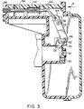
- Fig. 3 is a sectional view of the air inlet system as shown in Fig. 2 with the air inlet valve at a fully open position;
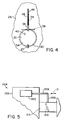
- Fig. 4 is an elevational view of the air inlet aperture taken in the direction of arrow C in Fig. 2;
- Fig. 5 is a schematic view of an alternate embodiment of the present invention;
- Fig. 6A is a schematic perspective view of a portion of an alternate embodiment of an air inlet system incorporating features of the present invention;
- Fig. 6B is a schematic cross-sectional view of the system shown in Fig. 6A with the inlet valve at a closed position and showing positions of members of the temperature controlled limiter assembly;
- Fig. 6C is a schematic cross-sectional view of the system shown in Fig. 6B with the inlet valve at an open position;
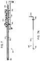
- Fig. 7 is a schematic partial cross-sectional view of an actuator assembly of the temperature controlled limiter assembly shown in Figs. 6A-6C; and
- Fig. 7A is a top view of the element and connector assembly used in the actuator assembly shown in Fig. 7.
-
- Referring to Fig. 1, there is shown a schematic view, with portions shown in cross section, of a portion of an
internal combustion engine 10 incorporating features of the present invention. Although the present invention will be described with reference to the embodiments shown in the drawings, it should be understood that features of the present invention can be embodied in various different forms and types of alternate embodiment. In addition, any suitable size, shape and type of elements or materials could be used. - The
engine 10 is a two cycle engine with acylinder 12,spark plug 14,carburetor 16, and anair inlet system 18 for thecarburetor 16. The present invention could also be used in a four cycle engine. In addition, other elements of theengine 10 which are conventional and well known are not described herein for the sake of clarity and simplicity. In the embodiment shown, theair inlet system 18 generally comprises amagnet 20, anair inlet valve 22, and a temperature controlledlimiter 24. Themagnet 20,valve 22, and part of thelimiter 24 are attached to and contained in aframe 26 that also forms part of theair filter 28 for theengine 10. However, in alternate embodiments, these components of theair inlet system 18 could be fully contained as part of the carburetor assembly. - Referring also to Fig. 4, the
frame 26 forms anair inlet aperture 30 between acentral area 32 of theair filter 28 and thecarburetor 16. Themagnet 20 is stationarily connected to theframe 26 at the bottom of theinlet aperture 30. Thevalve 22 is pivotably mounted to theframe 26 by apin 38. Thevalve 22 is movable between a fully closed position (illustrated in Fig. 2) and a fully open position (illustrated in Fig. 3). Thevalve 22 has afirst section 34 and asecond section 36. Thefirst section 34 is comprised of ferromagnetic material and has a general flat plate-like shape. Aport 40 may also be provided in thefirst section 34 if desired. The first section's primary function is to function as a choke valve at theinlet aperture 30. The function of a choke valve is very well known and, therefore, will not be described further. Thesecond section 36 has a general "L" shape forming alimiter receiving area 42 between its twolegs frame 26 also has aslot 46 at the top of theinlet aperture 30 to allow thesecond leg 45 to move therein. - The
limiter 24 generally comprises alever 48, aconnector 50, aspring 52, atube 54, and a temperatureresponsive element 56. Thelever 48 is pivotably mounted to theframe 26 atpin 58. Thelever 48 has afirst end 60 with apin 62, and asecond end 64. Thepin 62 is located in thereceiving area 42 of thevalve 22 between the twolegs connector 50 has afirst end 66 connected to the levelsecond end 64. Thelever 48 is pivotably mounted on thepin 58 between a first position, shown in Figs. 1 and 2, when theengine 10 is cold, and a second position, shown in Fig. 3, when theengine 10 is hot. Theslot 46 in theframe 26 allows theends slot 46. This allows thelever 48 free movement. As seen in comparing Figs. 1 and 2, thepin 62 and receivingarea 42 are suitably sized relative to each other such that thevalve 22 can move relative to thelever 48. However, thelever 48 can limit the range of the movement of thevalve 22 relative to theinlet aperture 30. This is discussed in further detail below. - The
spring 52 biases theconnector 50, relative to theframe 26, in a first direction indicated by arrow A. This is accomplished by means of thespring 52 pressing against washer 68 that presses againstenlarged section 70 of theconnector 50. Wall 72 of theframe 26 limits movement of the washer 68. This limits pushing action of the spring and movement of theconnector 50 in the direction A. Prestrain memory of theelement 56 limits the normal operational movement of theconnector 50 in an opposite second direction B (see Fig. 3). However, asecond wall 74 can also function as a limit by stopping washer 68 if a user inadvertently manually moves theconnector 50. Thesecond end 76 of theconnector 50 slidingly projects into thetube 54. Afirst end 78 of theelement 56 is fixedly connected to the connectorsecond end 76. Afirst end 80 of thetube 54 is stationarily held on theframe 26 by aretainer 82. The oppositesecond end 84 of thetube 54 has thesecond end 86 of theelement 56 stationarily connected thereto. Thetube 54 generally provides three functions. First, the tube functions as a cover for theelement 56 to prevent theelement 56 from damage. Second, thetube 54 functions as an anchor for thesecond end 86 of theelement 56 to be fixed to. Because thetube 54 is fixed to the frame, this fixes thesecond end 86 relative to theframe 26. Third, thetube 54 functions as a guide for the sliding movement of the connectorsecond end 76 inside the tube. Thetube 54 is made of a suitable material, such as copper, that can transfer heat from thecylinder 12 to theelement 56. Thetube 54 is suitably sized to fit between coolingfins 88 on the exterior of the cylinder. In alternate embodiments, the tube could be located at any suitable predetermined position on or in theengine 10 to respond to temperature changes of the engine at that location. Location of the tube at the top of thecylinder 12 is a preferred embodiment. This is because the temperature of the cylinder has the greatest effect on combustion in the cylinder. Thus, it is the most accurate location to use as a gauge to limit adjustment of thevalve 22. Limiting adjustment of thevalve 22 can affect the air/fuel mixture delivered by thecarburetor 16 to thecylinder 12. - In the embodiment shown, the
element 56 is comprised of an elongate member that functions similar to a cable or tie member between thesecond end 84 of thetube 54 and thesecond end 76 of theconnector 50. In a preferred embodiment, theelement 56 is comprised of nitinol wire. Nitinol consists of a group of Ti-Ni alloys that was developed by the Navy in the early 1960's for F-14 fighter jets. Nitinol was originally an acronym for Nickel-Titanium Naval Ordnance Laboratory, but is now a term used to identify Ti-Ni shape memory alloys. The shape-memory effect of such alloys is based on the continuous appearance and disappearance of martensite with falling and rising temperatures. Martensite is a metastable phase that forms when a phase stable at elevated temperature is cooled at a certain rate, thereby suppressing the formation of phases that are diffusion controlled. This is a thermoelastic behavior. A number of other characteristics associated with shape memory are referred to as pseudoelasticity or superelasticity, two-way shape-memory effect, martensite-to-martensite transformations, and rubber-like behavior. Other types of shape-memory alloys are known in the alloy materials industry. Nitinol wire can have a transition temperature ranging from -100°C to greater than 100°C. The transition temperature is controlled by additional alloying elements. - The martensite start temperature is the temperature at which martensite starts to form on cooling an austenite specimen. The martensite finish temperature is a lower temperature at which an elevated temperature phase has been completely transformed and the martinsite reaction is complete. On heating a martensite specimen, the temperature at which the reaction reverses to the elevated temperature phase is the austenite start temperature. Austenite reaction is complete at a higher austenite finish temperature. For the embodiment shown, the
element 56 is made of nitinol wire with an austenite start temperature of about 50°C - 65°C, an austenite finish temperature of about 80°C - 95°C, a martensite start temperature of about 65°C - 50°C, and a martensite finish temperature of about 40°C - 25°C. These temperatures are given for illustrational purposes only. Relatively small contraction and expansion of the length of the wire, such as less than 0.5% of the total length of the wire, can occure before and after transition. The above temperatures are given to illustrate when relatively large length changes of the wire start and stop. In alternate embodiments, other types of nitinol wire could be provided that have different austenite and martensite temperatures. In the embodiment shown, thenitinol wire 56 is FLEXINOL. FLEXINOL is a trademark of Dynalloy, Inc. of Irvine, California. The maximum temperature of thewire 56 should not exceed 300°C because, above this temperature, crystal growth begins to occur and consistent shape memory performance deteriorates. The transition temperature also changes with stress. Thus, based upon the amount of stress that thespring 52 exerts on thewire 56, the transition temperatures can be varied. Hence, different springs could be used to vary or configure the system's transition temperatures. For the transition temperatures mentioned above, thewire 56 was subjected to a load of 15,000 psi of cross sectional area. The percentage of extension and contraction of thewire 56 is about 4.5% of its length. - Referring now to Figs. 1, 2 and 4, the
limiter 24 is shown at a first position. This first position occurs when the temperature of thecylinder 12 is cold and thewire 56 is completely martensite. It should be understood that, as used herein, the term "cold" is intended to mean a temperature at thecylinder 12 of less than the austenite start temperature. In addition, the term "hot" is intended to mean a temperature at thecylinder 12 equal to or greater than the austenite finish temperature. In the first position of thelimiter 24, thespring 52 biases theconnector 50 in the position shown. Theconnector 50, in turn, maintains thelever 48 at the position shown. Theelement 56 keeps theconnector 50 from further movement in the direction A due to its connections at connectorsecond end 76 and tubesecond end 84. Although thelimiter 24 is shown at a single first position in Figs. 1 and 2, thevalve 22 is shown at two different positions. Fig. 2 is an illustration of when the engine is cold and is not operating. Fig. 1 is an illustration of when the engine is cold, but is operating. Fig. 2 shows thevalve 22 at a fully closed position. In this fully closed position the magnetic pull of themagnet 20 helps to keep thevalve 22 in the fully closed position until the engine is started. As seen in Fig. 4, thefirst section 34 of the valve substantially blocks theair inlet aperture 30. Thepin 62 on thelever 48 does not affect the position of thevalve 22 in this state. - Immediately after the
engine 10 is started, the inherent vacuum downstream of thevalve 22, caused by the engine operating, causes thevalve 22 to be pulled away from themagnet 20. Thevalve 22 pivots atpin 38. Since magnetic force decreases by the square of the distance from the magnet, the problem of themagnet 20 attracting the valve under normal running conditions of the engine is eliminated. As seen with reference to Fig. 1, the inflow of air throughair inlet aperture 30 pushes thefirst section 34 of thevalve 22 back to an open position. However, with thelimiter 24 at its first position, when thevalve 22 pivots atpin 38, thefirst arm 44 of the valvesecond section 36 contacts thepin 62 on thelever 48. This stops thevalve 22 from opening further. Thus, the open position ofvalve 22 in the cold operating state shown in Fig. 1 is not the fully open position. It is only a partially open position. Hence, an automatic partial-choke condition is provided in this cold operating state. - As the
engine 10 continues to operate, the temperature at thecylinder 12 will rise. Heat from thecylinder 12 is transferred by thetube 54 and air in thetube 54 to theelement 56. When the temperature of theelement 56 reaches the austenite start temperature, theelement 56 starts to thermoelastically longitudinally contract or shorten. Because the two ends 86, 78 of theelement 56 are respectively attached to thetube 54 andconnector 50, thetube 54 andconnector 50 are moved relative to each other as theelement 56 shortens. More specifically, because thetube 54 is fixed to theframe 26, theelement 56 pulls theconnector 50 further inside thetube 54. When the temperature of theelement 56 reaches the austenite finish temperature, theelement 56 stops contracting. As seen with reference to Fig. 3, this causes theconnector 50 to move thelever 48 to the second position shown. - Referring also to Fig. 3, the
air inlet system 18 is shown when theengine 10 is in a hot state or condition. This position of theair inlet system 18 exists whether or not the engine is operating. As can be seen, theelement 56 andconnector 50 have pulled, in the direction B, on thesecond end 64 of thelever 48 causing thelever 48 to pivot at thepin 58. This has moved thefirst end 66 of thelever 48. Thepin 62 on thefirst end 66 contacts thesecond leg 45 and prevents thevalve 22 from pivoting from the valve fully open position shown. Thus, even if theengine 10 is turned off, so long as theelement 56 remains above the martensite start temperature, thevalve 22 will be retained at its fully open position shown in Fig. 3. When theelement 56 cools past the martensite start temperature, it enters the metastable phase and starts to lengthen, pulled by thespring 52, to return to its original length. Thespring 52 biases theconnector 50 back to the position shown in Figs. 1 and 2 as the element further cools to the martensite finish temperature. This moves thelever 48 from its second position back to its first position. Thevalve 22 is thus able to return to its fully closed position shown in Fig. 2 through a combination of gravity and magnetic attraction when the valve gets close enough to themagnet 20 to be attracted. - If the
engine 10 is started again during the cooling between the martensite start temperature and the martensite finish temperature, thelever 48 will remain substantially stationary until heat is transferred from thecylinder 12 to theelement 56. As heat is transferred to theelement 56 it will begin to shorten again. In the embodiment shown, where air in thetube 54 is used as a heat transfer medium, a delay of about 5 to 10 seconds can occur in heat transfer. However, in alternate embodiments, other forms of heat transfer or heat transfer mediums could be used, such as grease, liquid, etc. In a preferred embodiment, the delay in heat transfer should be as small as possible. Air is used as the heat transfer medium in the embodiment shown because the delay of 5 to 10 seconds is minimal and the system is relatively inexpensive to manufacture and assemble. However, when the engine is started again, because thelever receiving area 42 of the valve second 36 is larger than thepin 62, the inflow of air through theinlet aperture 30 will immediately move thevalve 22 to at least a partially open position. - The present invention combines the features of the
magnet 20 with the temperature control of theelement 56 and design of the lever/valve interaction to provide an automatic choke or automatic air intake system for theengine 10. The system allows a cold engine to be started with an appropriate positioning of thevalve 22 before (Fig. 2) and after (Fig. 1) starting. As thecylinder 12 warms up, thesystem 18 automatically allows thevalve 22 to move from its partially open position shown in Fig. 1 to its fully open position shown in Fig. 3. If theengine 10 is stopped, but is still hot, theengine 10 can be restarted because thesystem 18 prevents thevalve 22 from returning to its fully closed position. If the engine was still hot and thevalve 22 returned to its fully closed position, the engine would not be able to restart because of an improper fuel/air mixture. Thus, the present invention provides a dependable and responsive automatic choke system for the engine. - Referring now to Fig. 5, a schematic view of an alternate embodiment of the present invention is shown. In the embodiment shown, a temperature
responsive element 200 is attached to thecylinder head 202 of anengine 204. The temperatureresponsive element 200 could include a shape-memory alloy. Theelement 200 has a first connectingrod 206 that is attached to a second connectingrod 208. Thesecond rod 208 is adapted to limit movement of achoke valve 210 inside thecarburetor 212 to a predetermined range of positions dependent upon whether thecylinder head 202 is hot or cold. Theelement 200 moves thesecond rod 208, by means of thefirst rod 206, dependent upon temperature of thecylinder head 202. This embodiment is intended to illustrate that features of the present invention can be embodied in various different types of embodiments. - Referring now to Figs. 6A-6C, schematic illustrations of an alternate embodiment is shown. In the embodiment shown, the
air inlet system 100 has aframe 102, anair filter cover 104, apermanent magnet 106, anair inlet valve 108, and a temperature controlledlimiter assembly 110. Theframe 102 has acover 112 and abody 114. Thecover 112 has anair inlet aperture 116 and ahole 118. Themagnet 106 is mounted in thehole 118. Thecover 112 is attached to the front of thebody 114 by suitable means (not shown). Thebody 114 has anair inlet conduit 120. Thevalve 108 has avalve plate 122 and apivot rod 124 fixedly attached thereto. Thepivot rod 124 is pivotably connected to thebody 114 with theplate 122 located in theconduit 120. Fixedly mounted to one end of thepivot rod 124 is anarm 126. Thearm 126 has a general "L" shape with anenlarged end 128 that acts as a weight for allowing gravity to assist in positioning thevalve 108. Theplate 122,rod 124 andarm 126 all move as an integral or unitary part. Thearm 126 is located on the exterior side of thebody 114. Thearm 126 is shown in Figs. 6B and 6C for illustrative purposes only. Thearm 126 would normally not be seen in the cross-sectional views shown. Thelimiter assembly 110 generally includes alever 130 and anactuator assembly 132. Thelever 130 is pivotably connected to thebody 114, on the same exterior side as thearm 126, by ascrew 134. Located at one end of thelever 130 is aprojection 136. Located at the opposite end is ahole 138. Thelever 130 is shown in Figs. 6B and 6C for illustrative purposes only. Thelever 130 would normally not be seen in the cross-sectional views shown. Theprojection 136 is located in the interior corner of the L-shapedarm 126 and, is adapted to make physical contact with thearm 126 to limit the arm's position on thebody 114. - Referring also to Fig. 7, the
actuator assembly 132 has aframe 140, atube 142, aspring 144, and an element andconnector assembly 146. Theframe 140 is adapted to be removably connected to thebody 114. Thetube 142 is fixedly mounted to theframe 140 by aconnector 148. The element andconnector assembly 146, also seen in Fig. 7A, generally comprises a temperature responsiveshape memory element 150, asplice 152, and ahook connector 154. Thesplice 152 is fixed to one end of theelement 150. Theconnector 154 is fixed to the opposite end of theelement 150. Theconnector 154 includes awasher 156. Thesplice 152 is fixed to one end of thetube 142 and theconnector 154 slidably extends out of the other end of thetube 142. Thespring 144 biases thewasher 156, and thus biases theconnector 154 in a direction away from thetube 142. The modularity of theactuator assembly 132 allows easier assembly of the temperature controlledlimiter assembly 110. The end of theconnector 154 is located in thehole 138 of thelever 130. Thus, theactuator assembly 132 is able to push and pull on one end of thelever 130. - Fig. 6B shows the
system 100 with the temperature controlledlimiter assembly 110 at a "cold" position and thevalve 108 at a closed position. In other words, the engine is cold and not running. When the engine is started thevalve 108 pops open (from the inflow of air), but only partially. Theprojection 136 stops thearm 126 from pivoting to a valve fully open position. Thus, a proper air/fuel mixture is provided for the "cold" engine. - Fig. 6C shows the temperature controlled
limiter assembly 110 at a "hot" position and thevalve 108 at a fully open position. In other words, the engine is hot and running. As seen in comparing Fig. 6B to Fig. 6C, when the engine heats up, theelement 150 contracts to pull theconnector 154 further into thetube 142. This moves thelever 130. This allows thearm 126 to move to a valve fully open position. If the engine is stopped, the weight of theend 128 will cause thevalve 108 to pivot towards the closed position. However, because the engine is still hot, theend 129 will be stopped by theprojection 136 to prevent the valve from returning to the fully closed position so long as the engine is hot. This embodiment, by locating thelever 130 andarm 126 outside thebody 114, reduces air losses past thevalve plate 122. - It should be understood that the foregoing description is only illustrative of the invention. Various alternatives and modifications can be devised by those skilled in the art without departing from the invention. Accordingly, the present invention is intended to embrace all such alternatives, modifications and variances which fall within the scope of the appended claims.
Claims (11)
- An air inlet control system for an internal combustion engine (10), the system comprising:characterised in thatan air inlet valve (22); anda limiter (24) adapted to limit movement of the air inlet (22) based upon temperature of a cylinder of the engine (10), the limiter (24) including a limit member (48) adapted to contact the air inlet valve (22),the limiter (24) comprises a tie member (56) connected to the limit member (48), the tie member (56) is comprised of a shape memory alloy with a portion extending between cooling fins (88) on the cylinder.
- A system as in claim 1 wherein the shape memory alloy is nitinol.
- A system as in claims 1 or 2 wherein the tie member (56) is a wire.
- A system as in any of claims 1 to 3 further comprising a magnet (20), at least a portion of the valve (22) being comprised of ferromagnetic material and being pivotably connected to a frame (26) with a fully closed position adjacent the magnet (20).
- A system as in one of the claims 1 to 4 wherein the valve (22) includes a limiter receiving area (42) with a portion of the mechanical linkage being located in the limiter receiving area (42), the valve (22) being movable relative to the portion of the mechanical linkage (48) between a first open position and a second closed position.
- A system as in one of claims 1 to 5 wherein the limiter (24) is movable between a first limiter position and a second limiter position, the first limiter position limiting the first open position of the valve (22) to less than a fully open position and, the second limiter position limiting the second closed position of the valve (22) to less than a fully closed position.
- A system as in one of claims 1 to 6 wherein the tie member (56) is adapted to contract when heated and expand back to its normal size when cooled, the tie member (56) having a first end connected to a lever (48) and a second end (86) connected to the frame (26).
- An air inlet control system for an internal combustion engine as in one of claims 1 to 7 wherein the limiter (24) has a lever (48), a spring (52), a connector (30) and the tie member (56), the lever (48) having a first end (62) located in a limiter receiving area (48), the tie member being connected to the lever (48) and having an end for positioning at a predetermined portion of the engine (10), the tie member (56) having an elongate straight shape adapted to longitudinally contract when heated and expand back to its normal size when cooled, wherein the connector (30) and spring (52) are between the lever (48) and the tie member (56) with the spring (52) biasing the connector (30) in a first direction.
- A system as in one of claims 1 to 9 further comprising a magnet (20) located proximate to the air inlet aperture (30) and the first end (34) of the valve (22) being comprised of ferromagnetic material.
- A system as in one of claims 1 to 9 wherein a second end of the valve (22) has a general "L" shape.
- A system as in one of claims 1 to 10 wherein the limiter (24) further comprises a tube (54) with the end (86) of the tie member (56) connected to a second end (84) of the tube (54), and a first end of the tube (54) being connected to a frame (26), the tie member (56) extending through the tube (54).
Applications Claiming Priority (2)
| Application Number | Priority Date | Filing Date | Title |
|---|---|---|---|
| US08/271,007 US5511519A (en) | 1994-07-05 | 1994-07-05 | Temperature adjusting automatic choke system |
| US271007 | 1999-03-17 |
Publications (3)
| Publication Number | Publication Date |
|---|---|
| EP0691468A2 EP0691468A2 (en) | 1996-01-10 |
| EP0691468A3 EP0691468A3 (en) | 1996-06-05 |
| EP0691468B1 true EP0691468B1 (en) | 1999-11-17 |
Family
ID=23033796
Family Applications (1)
| Application Number | Title | Priority Date | Filing Date |
|---|---|---|---|
| EP95107665A Expired - Lifetime EP0691468B1 (en) | 1994-07-05 | 1995-05-18 | Temperature adjusting automatic choke system |
Country Status (6)
| Country | Link |
|---|---|
| US (1) | US5511519A (en) |
| EP (1) | EP0691468B1 (en) |
| JP (1) | JPH0821305A (en) |
| AU (1) | AU682590B2 (en) |
| CA (1) | CA2146386C (en) |
| DE (1) | DE69513335T2 (en) |
Cited By (1)
| Publication number | Priority date | Publication date | Assignee | Title |
|---|---|---|---|---|
| US7611131B2 (en) | 2005-10-07 | 2009-11-03 | Husqvarna Ab | Carburetor start-stop mechanism |
Families Citing this family (16)
| Publication number | Priority date | Publication date | Assignee | Title |
|---|---|---|---|---|
| US5904124A (en) * | 1997-05-08 | 1999-05-18 | Briggs & Stratton Corporation | Enrichment apparatus for internal combustion engines |
| US6012420A (en) * | 1997-12-30 | 2000-01-11 | Briggs & Stratton Corporation | Automatic air inlet control system for an engine |
| US6039030A (en) * | 1998-04-06 | 2000-03-21 | Siemens Automotive Corporation | Fuel system containing a shape memory alloy |
| US5990777A (en) * | 1998-08-05 | 1999-11-23 | The Whitaker Corporation | Shape-memory wire actuated switch |
| JP4414115B2 (en) * | 2001-08-03 | 2010-02-10 | 本田技研工業株式会社 | Carburetor choke valve device |
| JP3990358B2 (en) * | 2001-10-22 | 2007-10-10 | ヤマハ発動機株式会社 | Auto choke control device |
| US6752110B2 (en) * | 2002-09-20 | 2004-06-22 | Briggs & Stratton Corporation | Electromechanical choke system for an internal combustion engine |
| US6830023B2 (en) * | 2002-11-07 | 2004-12-14 | Briggs & Stratton Corporation | Electromagnetic choke system for an internal combustion engine |
| US6990969B2 (en) * | 2003-07-30 | 2006-01-31 | Briggs And Stratton Corporation | Automatic choke for an engine |
| EP1621754B1 (en) * | 2004-07-26 | 2013-04-24 | Honda Motor Co., Ltd. | Automatic choke system for carburetor |
| US7597726B2 (en) * | 2006-01-20 | 2009-10-06 | Afton Chemical Corporation | Mannich detergents for hydrocarbon fuels |
| US7628387B1 (en) | 2008-07-03 | 2009-12-08 | Briggs And Stratton Corporation | Engine air/fuel mixing apparatus |
| US8495995B2 (en) | 2010-06-23 | 2013-07-30 | Briggs And Stratton Corporation | Automatic choke for an engine |
| US10054081B2 (en) | 2014-10-17 | 2018-08-21 | Kohler Co. | Automatic starting system |
| EP3332993B1 (en) | 2016-03-09 | 2025-04-30 | Maxell, Ltd. | Tire pressure detection system |
| CN114345283B (en) * | 2022-01-20 | 2023-05-30 | 方福食品科技有限公司 | High-purity sodium cyclamate production process and production device thereof |
Family Cites Families (13)
| Publication number | Priority date | Publication date | Assignee | Title |
|---|---|---|---|---|
| US1317047A (en) * | 1919-09-23 | Brooke | ||
| US1612597A (en) * | 1924-11-05 | 1926-12-28 | Alexander M Alexandrescu | Automatic carburetor |
| US2127653A (en) * | 1931-04-23 | 1938-08-23 | Glen R Sisson | Mixture control for internal combustion engines |
| US1996245A (en) * | 1932-09-16 | 1935-04-02 | Bendix Aviat Corp | Carburetor |
| US2124778A (en) * | 1934-07-09 | 1938-07-26 | Bendix Prod Corp | Carburetor |
| US2548334A (en) * | 1947-03-17 | 1951-04-10 | Briggs & Stratton Corp | Automatic choke control for internal-combustion engines |
| US3392965A (en) * | 1967-02-13 | 1968-07-16 | Ford Motor Co | Fuel metering system for an air valve carburetor |
| US3807709A (en) * | 1970-09-24 | 1974-04-30 | Nippon Denso Co | Carburetor |
| JPS6146454A (en) * | 1984-08-09 | 1986-03-06 | Sanshin Ind Co Ltd | Choke valve of carburetor |
| JPS61106956A (en) * | 1984-10-29 | 1986-05-24 | Nippon Carbureter Co Ltd | Manual choke carburetor |
| JPS6251744A (en) * | 1985-08-30 | 1987-03-06 | Keihin Seiki Mfg Co Ltd | Autochoke device for carburetor |
| IT214591Z2 (en) * | 1988-05-27 | 1990-05-09 | Fiat Auto Spa | DEVICE FOR ADJUSTING THE INTAKE AIR FLOW RATE IN A CARBURETOR OF AN ENDOTHERMAL ENGINE |
| US5299548A (en) * | 1992-12-18 | 1994-04-05 | The Center For Innovative Technology | Carburetor with lagging bypass air valve |
-
1994
- 1994-07-05 US US08/271,007 patent/US5511519A/en not_active Expired - Fee Related
-
1995
- 1995-04-05 CA CA002146386A patent/CA2146386C/en not_active Expired - Fee Related
- 1995-05-09 JP JP7110478A patent/JPH0821305A/en active Pending
- 1995-05-18 DE DE69513335T patent/DE69513335T2/en not_active Expired - Fee Related
- 1995-05-18 EP EP95107665A patent/EP0691468B1/en not_active Expired - Lifetime
- 1995-05-19 AU AU20166/95A patent/AU682590B2/en not_active Ceased
Cited By (1)
| Publication number | Priority date | Publication date | Assignee | Title |
|---|---|---|---|---|
| US7611131B2 (en) | 2005-10-07 | 2009-11-03 | Husqvarna Ab | Carburetor start-stop mechanism |
Also Published As
| Publication number | Publication date |
|---|---|
| US5511519A (en) | 1996-04-30 |
| DE69513335T2 (en) | 2000-04-13 |
| AU2016695A (en) | 1996-01-18 |
| DE69513335D1 (en) | 1999-12-23 |
| EP0691468A3 (en) | 1996-06-05 |
| CA2146386A1 (en) | 1996-01-06 |
| EP0691468A2 (en) | 1996-01-10 |
| AU682590B2 (en) | 1997-10-09 |
| JPH0821305A (en) | 1996-01-23 |
| CA2146386C (en) | 2004-06-29 |
Similar Documents
| Publication | Publication Date | Title |
|---|---|---|
| CA2146386C (en) | Temperature adjusting automatic choke system | |
| US3974808A (en) | Air intake duct assembly | |
| AU2004260947B2 (en) | Automatic choke for an engine | |
| CA1098399A (en) | Diesel engine starting control | |
| US6145487A (en) | Automatic air inlet control system for an engine | |
| JP2012052549A (en) | Carburetor start-stop mechanism | |
| US5904124A (en) | Enrichment apparatus for internal combustion engines | |
| US5121727A (en) | Adjuster for a throttle valve | |
| US3886241A (en) | Carburetor cold enrichment control | |
| US3947531A (en) | Carburetor with controlled fast idle cam | |
| US3789814A (en) | Ambient temperature regulated choke | |
| US4003355A (en) | Carburetor choke valve control device | |
| GB2084250A (en) | Shape memory effect controlled-air intake for internal combustion engines | |
| US2956558A (en) | Means for starting and operating internal combustion engines | |
| JPH0350091B2 (en) | ||
| US3732856A (en) | Gasoline engine choke delay devices | |
| US3180576A (en) | Means for mounting a thermostatic element | |
| US5992829A (en) | Temperature compensated choke | |
| US2995348A (en) | Choke valve damper | |
| JPH0315787Y2 (en) | ||
| US4333888A (en) | Carburetor accelerator pump stroke control | |
| US3622131A (en) | Choke plate closing retarding means for a carburetor automatic choke | |
| JPS6229645Y2 (en) | ||
| JPH11508658A (en) | Device for adjusting the temperature of the intake air of an internal combustion engine | |
| JP4145846B2 (en) | Vaporizer auto choke device |
Legal Events
| Date | Code | Title | Description |
|---|---|---|---|
| PUAI | Public reference made under article 153(3) epc to a published international application that has entered the european phase |
Free format text: ORIGINAL CODE: 0009012 |
|
| AK | Designated contracting states |
Kind code of ref document: A2 Designated state(s): DE FR GB IT SE |
|
| PUAL | Search report despatched |
Free format text: ORIGINAL CODE: 0009013 |
|
| AK | Designated contracting states |
Kind code of ref document: A3 Designated state(s): DE FR GB IT SE |
|
| 17P | Request for examination filed |
Effective date: 19961025 |
|
| 17Q | First examination report despatched |
Effective date: 19980629 |
|
| GRAG | Despatch of communication of intention to grant |
Free format text: ORIGINAL CODE: EPIDOS AGRA |
|
| GRAG | Despatch of communication of intention to grant |
Free format text: ORIGINAL CODE: EPIDOS AGRA |
|
| GRAH | Despatch of communication of intention to grant a patent |
Free format text: ORIGINAL CODE: EPIDOS IGRA |
|
| GRAH | Despatch of communication of intention to grant a patent |
Free format text: ORIGINAL CODE: EPIDOS IGRA |
|
| GRAA | (expected) grant |
Free format text: ORIGINAL CODE: 0009210 |
|
| AK | Designated contracting states |
Kind code of ref document: B1 Designated state(s): DE FR GB IT SE |
|
| REF | Corresponds to: |
Ref document number: 69513335 Country of ref document: DE Date of ref document: 19991223 |
|
| ITF | It: translation for a ep patent filed | ||
| ET | Fr: translation filed | ||
| PLBE | No opposition filed within time limit |
Free format text: ORIGINAL CODE: 0009261 |
|
| STAA | Information on the status of an ep patent application or granted ep patent |
Free format text: STATUS: NO OPPOSITION FILED WITHIN TIME LIMIT |
|
| 26N | No opposition filed | ||
| REG | Reference to a national code |
Ref country code: GB Ref legal event code: IF02 |
|
| PGFP | Annual fee paid to national office [announced via postgrant information from national office to epo] |
Ref country code: GB Payment date: 20060411 Year of fee payment: 12 |
|
| PGFP | Annual fee paid to national office [announced via postgrant information from national office to epo] |
Ref country code: SE Payment date: 20060413 Year of fee payment: 12 |
|
| PGFP | Annual fee paid to national office [announced via postgrant information from national office to epo] |
Ref country code: DE Payment date: 20060418 Year of fee payment: 12 |
|
| PGFP | Annual fee paid to national office [announced via postgrant information from national office to epo] |
Ref country code: FR Payment date: 20060523 Year of fee payment: 12 |
|
| PGFP | Annual fee paid to national office [announced via postgrant information from national office to epo] |
Ref country code: IT Payment date: 20060531 Year of fee payment: 12 |
|
| EUG | Se: european patent has lapsed | ||
| GBPC | Gb: european patent ceased through non-payment of renewal fee |
Effective date: 20070518 |
|
| REG | Reference to a national code |
Ref country code: FR Ref legal event code: ST Effective date: 20080131 |
|
| PG25 | Lapsed in a contracting state [announced via postgrant information from national office to epo] |
Ref country code: DE Free format text: LAPSE BECAUSE OF NON-PAYMENT OF DUE FEES Effective date: 20071201 |
|
| PG25 | Lapsed in a contracting state [announced via postgrant information from national office to epo] |
Ref country code: GB Free format text: LAPSE BECAUSE OF NON-PAYMENT OF DUE FEES Effective date: 20070518 |
|
| PG25 | Lapsed in a contracting state [announced via postgrant information from national office to epo] |
Ref country code: SE Free format text: LAPSE BECAUSE OF NON-PAYMENT OF DUE FEES Effective date: 20070519 |
|
| PG25 | Lapsed in a contracting state [announced via postgrant information from national office to epo] |
Ref country code: FR Free format text: LAPSE BECAUSE OF NON-PAYMENT OF DUE FEES Effective date: 20070531 |
|
| PG25 | Lapsed in a contracting state [announced via postgrant information from national office to epo] |
Ref country code: IT Free format text: LAPSE BECAUSE OF NON-PAYMENT OF DUE FEES Effective date: 20070518 |