EP0691279A2 - Container for medical waste - Google Patents
Container for medical waste Download PDFInfo
- Publication number
- EP0691279A2 EP0691279A2 EP95304680A EP95304680A EP0691279A2 EP 0691279 A2 EP0691279 A2 EP 0691279A2 EP 95304680 A EP95304680 A EP 95304680A EP 95304680 A EP95304680 A EP 95304680A EP 0691279 A2 EP0691279 A2 EP 0691279A2
- Authority
- EP
- European Patent Office
- Prior art keywords
- obstructor
- configuration
- assembly according
- sealing
- obstructing
- Prior art date
- Legal status (The legal status is an assumption and is not a legal conclusion. Google has not performed a legal analysis and makes no representation as to the accuracy of the status listed.)
- Withdrawn
Links
Images
Classifications
-
- A—HUMAN NECESSITIES
- A61—MEDICAL OR VETERINARY SCIENCE; HYGIENE
- A61M—DEVICES FOR INTRODUCING MEDIA INTO, OR ONTO, THE BODY; DEVICES FOR TRANSDUCING BODY MEDIA OR FOR TAKING MEDIA FROM THE BODY; DEVICES FOR PRODUCING OR ENDING SLEEP OR STUPOR
- A61M5/00—Devices for bringing media into the body in a subcutaneous, intra-vascular or intramuscular way; Accessories therefor, e.g. filling or cleaning devices, arm-rests
- A61M5/178—Syringes
- A61M5/31—Details
- A61M5/32—Needles; Details of needles pertaining to their connection with syringe or hub; Accessories for bringing the needle into, or holding the needle on, the body; Devices for protection of needles
- A61M5/3205—Apparatus for removing or disposing of used needles or syringes, e.g. containers; Means for protection against accidental injuries from used needles
-
- A—HUMAN NECESSITIES
- A61—MEDICAL OR VETERINARY SCIENCE; HYGIENE
- A61B—DIAGNOSIS; SURGERY; IDENTIFICATION
- A61B50/00—Containers, covers, furniture or holders specially adapted for surgical or diagnostic appliances or instruments, e.g. sterile covers
- A61B50/30—Containers specially adapted for packaging, protecting, dispensing, collecting or disposing of surgical or diagnostic appliances or instruments
- A61B50/36—Containers specially adapted for packaging, protecting, dispensing, collecting or disposing of surgical or diagnostic appliances or instruments for collecting or disposing of used articles
- A61B50/362—Containers specially adapted for packaging, protecting, dispensing, collecting or disposing of surgical or diagnostic appliances or instruments for collecting or disposing of used articles for sharps
-
- A—HUMAN NECESSITIES
- A61—MEDICAL OR VETERINARY SCIENCE; HYGIENE
- A61B—DIAGNOSIS; SURGERY; IDENTIFICATION
- A61B50/00—Containers, covers, furniture or holders specially adapted for surgical or diagnostic appliances or instruments, e.g. sterile covers
- A61B2050/005—Containers, covers, furniture or holders specially adapted for surgical or diagnostic appliances or instruments, e.g. sterile covers with a lid or cover
- A61B2050/0051—Containers, covers, furniture or holders specially adapted for surgical or diagnostic appliances or instruments, e.g. sterile covers with a lid or cover closable by rotation
- A61B2050/0054—Containers, covers, furniture or holders specially adapted for surgical or diagnostic appliances or instruments, e.g. sterile covers with a lid or cover closable by rotation about the central longitudinal axis perpendicular to the lid plane
-
- A—HUMAN NECESSITIES
- A61—MEDICAL OR VETERINARY SCIENCE; HYGIENE
- A61B—DIAGNOSIS; SURGERY; IDENTIFICATION
- A61B50/00—Containers, covers, furniture or holders specially adapted for surgical or diagnostic appliances or instruments, e.g. sterile covers
- A61B2050/005—Containers, covers, furniture or holders specially adapted for surgical or diagnostic appliances or instruments, e.g. sterile covers with a lid or cover
- A61B2050/0051—Containers, covers, furniture or holders specially adapted for surgical or diagnostic appliances or instruments, e.g. sterile covers with a lid or cover closable by rotation
- A61B2050/0056—Containers, covers, furniture or holders specially adapted for surgical or diagnostic appliances or instruments, e.g. sterile covers with a lid or cover closable by rotation about a lateral axis in the lid plane
-
- A—HUMAN NECESSITIES
- A61—MEDICAL OR VETERINARY SCIENCE; HYGIENE
- A61B—DIAGNOSIS; SURGERY; IDENTIFICATION
- A61B50/00—Containers, covers, furniture or holders specially adapted for surgical or diagnostic appliances or instruments, e.g. sterile covers
- A61B2050/005—Containers, covers, furniture or holders specially adapted for surgical or diagnostic appliances or instruments, e.g. sterile covers with a lid or cover
- A61B2050/0058—Containers, covers, furniture or holders specially adapted for surgical or diagnostic appliances or instruments, e.g. sterile covers with a lid or cover closable by translation
- A61B2050/006—Containers, covers, furniture or holders specially adapted for surgical or diagnostic appliances or instruments, e.g. sterile covers with a lid or cover closable by translation perpendicular to the lid plane, e.g. by a downward movement
-
- A—HUMAN NECESSITIES
- A61—MEDICAL OR VETERINARY SCIENCE; HYGIENE
- A61B—DIAGNOSIS; SURGERY; IDENTIFICATION
- A61B50/00—Containers, covers, furniture or holders specially adapted for surgical or diagnostic appliances or instruments, e.g. sterile covers
- A61B2050/005—Containers, covers, furniture or holders specially adapted for surgical or diagnostic appliances or instruments, e.g. sterile covers with a lid or cover
- A61B2050/0066—Containers, covers, furniture or holders specially adapted for surgical or diagnostic appliances or instruments, e.g. sterile covers with a lid or cover with additional sealing means, e.g. O-ring
-
- A—HUMAN NECESSITIES
- A61—MEDICAL OR VETERINARY SCIENCE; HYGIENE
- A61B—DIAGNOSIS; SURGERY; IDENTIFICATION
- A61B50/00—Containers, covers, furniture or holders specially adapted for surgical or diagnostic appliances or instruments, e.g. sterile covers
- A61B2050/005—Containers, covers, furniture or holders specially adapted for surgical or diagnostic appliances or instruments, e.g. sterile covers with a lid or cover
- A61B2050/0067—Types of closures or fasteners
- A61B2050/0076—Types of closures or fasteners having additional locking means
-
- A—HUMAN NECESSITIES
- A61—MEDICAL OR VETERINARY SCIENCE; HYGIENE
- A61B—DIAGNOSIS; SURGERY; IDENTIFICATION
- A61B50/00—Containers, covers, furniture or holders specially adapted for surgical or diagnostic appliances or instruments, e.g. sterile covers
- A61B2050/005—Containers, covers, furniture or holders specially adapted for surgical or diagnostic appliances or instruments, e.g. sterile covers with a lid or cover
- A61B2050/0067—Types of closures or fasteners
- A61B2050/0083—Snap connection
-
- A—HUMAN NECESSITIES
- A61—MEDICAL OR VETERINARY SCIENCE; HYGIENE
- A61B—DIAGNOSIS; SURGERY; IDENTIFICATION
- A61B50/00—Containers, covers, furniture or holders specially adapted for surgical or diagnostic appliances or instruments, e.g. sterile covers
- A61B2050/005—Containers, covers, furniture or holders specially adapted for surgical or diagnostic appliances or instruments, e.g. sterile covers with a lid or cover
- A61B2050/0089—Containers, covers, furniture or holders specially adapted for surgical or diagnostic appliances or instruments, e.g. sterile covers with a lid or cover having permanent closure means
Definitions
- the present invention relates to a container and to a closure therefor. It particularly relates to a container and closure for use in the disposal of medical waste.
- EP-A-0,367,422 discloses a closure assembly for a container, particularly a "sharps bin". It provides a container lid having an access aperture and an obstructor member which is slidable between an obstructing configuration and an open configuration. In the obstructing configuration, it closes the access aperture. It includes a locking piece including a slidable pin. When the obstructor member is in the obstructing configuration, the pin can be depressed so that it projects beneath the obstructor member and engages behind a detent formation of the lid, thus preventing the obstructor member from being slid out of the obstructing configuration.
- the present invention provides a closure assembly for a container comprising a wall member having an access aperture, and an obstructor member mounted on the wall member so as to be displaceable between an open configuration in which the access aperture is accessible, and an obstructing configuration; wherein the obstructor member has a portion which is in register with the access aperture in the obstructing configuration; at least that portion of the obstructor member being displaceable towards the aperture in the obstructing configuration, and comprising sealing means for sealing around the access aperture.
- the displacement of the obstructor member between the open and obstructing configurations involves motion generally in the plane of the wall member, e.g. rotary motion; and the displacement towards the aperture to effect sealing around it involves displacement having at least a component into the plane of the wall member.
- the obstructor member may be just a portion of the obstructor member that is displaceable towards the aperture for sealing, e.g. a hinged flap.
- the entire obstructor member is displaced.
- the obstructor member may be rotatably mounted on the wall member so as to be rotatable between the open and obstructing configurations.
- the sealing displacement may then involve axial displacement of the member.
- the axial displacement is possible only when the obstructor member is in the obstructing configuration, e.g. because then a projection on the obstructor member and a recess or opening on the wall member (or vice versa) are in register.
- the arrangement is such that the obstructor member is locked in the sealing configuration and is resistant to withdrawal.
- the axial movement may involve an abutting portion moving beyond a projection which must be temporarily deformed to permit this.
- the shaping of the abutment and the projection may be mutually adapted so that motion in the reverse direction is resisted.
- one component may be chamfered to facilitate the sealing motion, whereas its profile at the other side is abrupt, so as to resist the contrary motion.
- the sealing means may be a gasket of sealing material which entirely covers, and extends laterally beyond, the access aperture. Alternatively it may be an annular seal in the region of the periphery of the access aperture (when the obstructor member is in the obstructing configuration).
- the gasket may be a closed-cell foam material, e.g. of PVC or polyurethane.
- the closure assembly could be integral with a container. But more normally, it will be a separate component (generally a lid) for connection thereto.
- the invention provides a combination of a lid and a container, each having a respective rim portion by which they are mutually engageable, there being complementary engagement formations including sealing means such that their engagement produces a liquid-tight seal.
- they will be snap-engageable, one component having a flange which snap-engages behind a flange of the other component. It can be arranged that this snap-engagement causes resilient compression of a seal element.
- Preferred embodiments incorporate both aspects.
- Fig. 1 shows a lid member 10 having a main wall 12 which is generally square with rounded corners.
- a peripheral wall 14 extends downwardly and outwardly from the periphery.
- the main wall 12 has a recessed circular central region 16, delimited by an outer annular channel 18.
- the inner wall 20 also has a small recess 34, radially outwardly of the arcuate channel.
- the annular channel 18 is defined by an outer wall having radial projections. These form two sets differing in axial position. There is a lower set 36, in this example numbering five relatively large projections; and there is an upper set 38, in this example numbering six smaller projections.
- the upper surfaces of the lower projections 36 define a level which is spaced beneath the level defined by the lower surfaces of the upper projections.
- the lower projections are spaced above the floor of the annular channel 18.
- the obstructor member 50 shown in Figs. 2 to 4 is a circular disc having a main circular, planar wall 52 with a depending peripheral rim 53. At a lower region, this has an outwardly extending flange 54. This is generally of approximately rectangular section, as shown in Fig. 3. However, in a plurality of regions corresponding in number and angular distribution to the lower projections 36 in the annular channel 18 of the lid, the flange has a form shown in Fig. 4, with a lower surface 55 which is chamfered, or otherwise made more gradual.
- the undersurface of the circular wall 52 has a central tubular spigot 56 with a spaced pair of interrupted circumferential ribs 58.
- a region of the member 50 is recessed, so as to provide a large projection 62 on the lower face.
- the gasket is a flat pad of resilient closed-cell PVC foam.
- the projection 62 is somewhat smaller than the access aperture 24 of the lid.
- the underside of the member 50 also has a small, radially outer projection 66 and an approximately W-shaped projection 68.
- the recess corresponding to the projection 62 serves as a handgrip. This may be aided by one or more ribs extending across it.
- the lid and obstructor member are dimensioned so that the member 50 can be placed on the lid, with the peripheral wall of the member received in the annular channel 18, and the spigot 56 engaged in the central aperture 22.
- the member is pushed down so that the outer flange 54 snap-engages under the upper projections 38, and rests on the upper surfaces of the lower projections 36; and the edge of the central aperture engages between the projections 58.
- the W-shaped projection 68 extends into the arcuate channel 26, whose extent thus delimits the rotation of the member. When it is fully rotated anti-clockwise, its access opening 60 is in register with the access aperture 24 of the lid. As it is rotated clockwise, there is a perceptible click as the W-shaped projection passes the nib 34.
- the small outer projection 66 is then in register with the recess 34 of the lid. To effect locking of the obstructor member, it can then be pushed down. The spigot 56 is received more deeply, so that engagement is above the upper projection 58. Furthermore, the peripheral flange 54 is pushed past the lower projections 36, and engages beneath them. This pushing past is made possible by the fact that, in the fully clockwise configuration, it is the chamfered regions of the flange which overlie the lower projections 36.
- the member 50 is locked down, held against rotation by the engagement of the small projection 66 in the recess 34, and the gasket 64 seals around the access opening 24 and also the central opening 22 of the lid. The sealing can be reliably fluid-tight.
- Figs. 5 and 6 show a similar embodiment, and corresponding elements bear the same reference numbers.
- This embodiment also has features disclosed in our earlier application EP-A-0,367,422.
- the obstructor member instead of having a fixed W-shaped projection 68 that engages in the arcuate channel 26 of the lid, the obstructor member has a pin assembly 80 as disclosed in that earlier application.
- the arcuate channel terminates in a deeper recess 32. When the pin reaches this, it can be depressed to lock therein.
- the pin assembly also provides a handgrip.
- the gasket 64 may be a complete pad, rather than an annulus. It may be adhered to the obstructor element.
- Fig. 7 shows another variant in which sealing about the access aperture is effected by moving only a part of the obstructor member 150.
- the gasket 162 is carried on a hinged flap 200 which is a part of the obstructor member, having formations that snap-engage behind projections in the annular channel 18 of the lid, when it is pushed down.
- the hinged flap is an integrally-formed part of the member 150, with the hinge being provided by a line of weakness. But it could be a separate element, with a hinge connection.
- Fig. 8 shows a variant of this that provides sealing.
- one component 220 (which may be the lid) has a channel defined between an inner portion 222 and an outer portion 224, which is of greater extent and terminates in an inwardly extending rib 226.
- the other component 228 has a rim portion 230 that extends into the channel between the portions 222,224 of the other component. It also has an outwardly extending flange 232 which is inwardly resiliently deformable, and is dimensioned to snap-engage behind the rib 226.
- the outer flange 224 of the first component and the flange 232 of the second component are modified to provide a seat for a gasket element and a sealing face.
- the flange 224 of the first component is stepped to provide a surface for a sealing element 234, and the flange 232 of the second component has an upstanding element that provides a sealing surface 236.
Abstract
Description
- The present invention relates to a container and to a closure therefor. It particularly relates to a container and closure for use in the disposal of medical waste.
- Our earlier European specification, EP-A-0,367,422 discloses a closure assembly for a container, particularly a "sharps bin". It provides a container lid having an access aperture and an obstructor member which is slidable between an obstructing configuration and an open configuration. In the obstructing configuration, it closes the access aperture. It includes a locking piece including a slidable pin. When the obstructor member is in the obstructing configuration, the pin can be depressed so that it projects beneath the obstructor member and engages behind a detent formation of the lid, thus preventing the obstructor member from being slid out of the obstructing configuration.
- In one aspect, the present invention provides a closure assembly for a container comprising a wall member having an access aperture, and an obstructor member mounted on the wall member so as to be displaceable between an open configuration in which the access aperture is accessible, and an obstructing configuration; wherein the obstructor member has a portion which is in register with the access aperture in the obstructing configuration; at least that portion of the obstructor member being displaceable towards the aperture in the obstructing configuration, and comprising sealing means for sealing around the access aperture.
- Preferably the displacement of the obstructor member between the open and obstructing configurations involves motion generally in the plane of the wall member, e.g. rotary motion; and the displacement towards the aperture to effect sealing around it involves displacement having at least a component into the plane of the wall member.
- There may be just a portion of the obstructor member that is displaceable towards the aperture for sealing, e.g. a hinged flap. Preferably, however, the entire obstructor member is displaced. Thus the obstructor member may be rotatably mounted on the wall member so as to be rotatable between the open and obstructing configurations. The sealing displacement may then involve axial displacement of the member. Preferably the axial displacement is possible only when the obstructor member is in the obstructing configuration, e.g. because then a projection on the obstructor member and a recess or opening on the wall member (or vice versa) are in register. Preferably the arrangement is such that the obstructor member is locked in the sealing configuration and is resistant to withdrawal. Thus the axial movement may involve an abutting portion moving beyond a projection which must be temporarily deformed to permit this. The shaping of the abutment and the projection may be mutually adapted so that motion in the reverse direction is resisted. Thus one component may be chamfered to facilitate the sealing motion, whereas its profile at the other side is abrupt, so as to resist the contrary motion.
- The sealing means may be a gasket of sealing material which entirely covers, and extends laterally beyond, the access aperture. Alternatively it may be an annular seal in the region of the periphery of the access aperture (when the obstructor member is in the obstructing configuration). The gasket may be a closed-cell foam material, e.g. of PVC or polyurethane.
- The closure assembly could be integral with a container. But more normally, it will be a separate component (generally a lid) for connection thereto. In another aspect, the invention provides a combination of a lid and a container, each having a respective rim portion by which they are mutually engageable, there being complementary engagement formations including sealing means such that their engagement produces a liquid-tight seal. Generally they will be snap-engageable, one component having a flange which snap-engages behind a flange of the other component. It can be arranged that this snap-engagement causes resilient compression of a seal element. Preferred embodiments incorporate both aspects.
- Some embodiments of the invention will now be described in more detail with reference to the accompanying drawings in which:
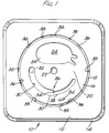
- Fig. 1 is a plan view of part of a first embodiment, namely a lid without an obstructor member;
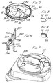
- Fig. 2 is a perspective view from beneath of an obstructor member for use with the lid of Fig. 1;
- Figs. 3 and 4 are sectional views of the rim region of the obstructor member taken at III-III and IV-IV of Fig. 2 respectively.
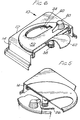
- Figs. 5 and 6 are a pair of perspective views from above of a second embodiment of the invention, partly cut away;
- Fig. 7 is a perspective view from above showing part of a third embodiment; and
- Fig. 8 is a vertical section through the region of connection of a lid and a container.
- Fig. 1 shows a
lid member 10 having amain wall 12 which is generally square with rounded corners. Aperipheral wall 14 extends downwardly and outwardly from the periphery. Themain wall 12 has a recessed circularcentral region 16, delimited by an outerannular channel 18. Within this there is aninner wall 20 penetrated by a centralcircular socket 22 and a large access opening 24. It has a recess defining a coaxialarcuate channel 26 having anarrow portion 28 and awider portion 30 which, in some embodiments, terminates in adeeper cavity 32. At the junction between the narrow andwide portions radial nib 34 that further narrows the mouth of thenarrow portion 28. Theinner wall 20 also has asmall recess 34, radially outwardly of the arcuate channel. - The
annular channel 18 is defined by an outer wall having radial projections. These form two sets differing in axial position. There is alower set 36, in this example numbering five relatively large projections; and there is anupper set 38, in this example numbering six smaller projections. The upper surfaces of thelower projections 36 define a level which is spaced beneath the level defined by the lower surfaces of the upper projections. The lower projections are spaced above the floor of theannular channel 18. - The
obstructor member 50 shown in Figs. 2 to 4 is a circular disc having a main circular,planar wall 52 with a dependingperipheral rim 53. At a lower region, this has an outwardly extendingflange 54. This is generally of approximately rectangular section, as shown in Fig. 3. However, in a plurality of regions corresponding in number and angular distribution to thelower projections 36 in theannular channel 18 of the lid, the flange has a form shown in Fig. 4, with alower surface 55 which is chamfered, or otherwise made more gradual. - The undersurface of the
circular wall 52 has a centraltubular spigot 56 with a spaced pair of interruptedcircumferential ribs 58. There is a large access opening 60 capable of overlying theaccess aperture 24 of the lid. A region of themember 50 is recessed, so as to provide alarge projection 62 on the lower face. This is embraced by agasket member 64, which also surrounds thespigot 56. The gasket is a flat pad of resilient closed-cell PVC foam. Theprojection 62 is somewhat smaller than theaccess aperture 24 of the lid. - The underside of the
member 50 also has a small, radiallyouter projection 66 and an approximately W-shaped projection 68. On the top side of themember 50, the recess corresponding to theprojection 62 serves as a handgrip. This may be aided by one or more ribs extending across it. - The lid and obstructor member are dimensioned so that the
member 50 can be placed on the lid, with the peripheral wall of the member received in theannular channel 18, and thespigot 56 engaged in thecentral aperture 22. The member is pushed down so that theouter flange 54 snap-engages under theupper projections 38, and rests on the upper surfaces of thelower projections 36; and the edge of the central aperture engages between theprojections 58. The W-shaped projection 68 extends into thearcuate channel 26, whose extent thus delimits the rotation of the member. When it is fully rotated anti-clockwise, its access opening 60 is in register with theaccess aperture 24 of the lid. As it is rotated clockwise, there is a perceptible click as the W-shaped projection passes thenib 34. When themember 50 is rotated clockwise as far as it can go, the smallouter projection 66 is then in register with therecess 34 of the lid. To effect locking of the obstructor member, it can then be pushed down. Thespigot 56 is received more deeply, so that engagement is above theupper projection 58. Furthermore, theperipheral flange 54 is pushed past thelower projections 36, and engages beneath them. This pushing past is made possible by the fact that, in the fully clockwise configuration, it is the chamfered regions of the flange which overlie thelower projections 36. Thus themember 50 is locked down, held against rotation by the engagement of thesmall projection 66 in therecess 34, and thegasket 64 seals around the access opening 24 and also thecentral opening 22 of the lid. The sealing can be reliably fluid-tight. - Figs. 5 and 6 show a similar embodiment, and corresponding elements bear the same reference numbers. This embodiment also has features disclosed in our earlier application EP-A-0,367,422. Thus, instead of having a fixed W-shaped
projection 68 that engages in thearcuate channel 26 of the lid, the obstructor member has apin assembly 80 as disclosed in that earlier application. As shown in Fig. 1, the arcuate channel terminates in adeeper recess 32. When the pin reaches this, it can be depressed to lock therein. The pin assembly also provides a handgrip. There is norecess 62 in the obstructor member. Thegasket 64 may be a complete pad, rather than an annulus. It may be adhered to the obstructor element. - Fig. 7 shows another variant in which sealing about the access aperture is effected by moving only a part of the
obstructor member 150. Thegasket 162 is carried on a hingedflap 200 which is a part of the obstructor member, having formations that snap-engage behind projections in theannular channel 18 of the lid, when it is pushed down. In this example, the hinged flap is an integrally-formed part of themember 150, with the hinge being provided by a line of weakness. But it could be a separate element, with a hinge connection. - The engagement of the lid on a container generally involves a rim portion of one component being received in a channel of the other component with some snap-engagement. Fig. 8 shows a variant of this that provides sealing. Thus one component 220 (which may be the lid) has a channel defined between an
inner portion 222 and an outer portion 224, which is of greater extent and terminates in an inwardly extendingrib 226. Theother component 228 has arim portion 230 that extends into the channel between the portions 222,224 of the other component. It also has an outwardly extendingflange 232 which is inwardly resiliently deformable, and is dimensioned to snap-engage behind therib 226. In this modified version, the outer flange 224 of the first component and theflange 232 of the second component are modified to provide a seat for a gasket element and a sealing face. In this example, the flange 224 of the first component is stepped to provide a surface for asealing element 234, and theflange 232 of the second component has an upstanding element that provides a sealingsurface 236.
Claims (13)
Applications Claiming Priority (2)
| Application Number | Priority Date | Filing Date | Title |
|---|---|---|---|
| GB9413451A GB9413451D0 (en) | 1994-07-04 | 1994-07-04 | Container for medical waste |
| GB9413451 | 1994-07-04 |
Publications (2)
| Publication Number | Publication Date |
|---|---|
| EP0691279A2 true EP0691279A2 (en) | 1996-01-10 |
| EP0691279A3 EP0691279A3 (en) | 1996-06-26 |
Family
ID=10757778
Family Applications (1)
| Application Number | Title | Priority Date | Filing Date |
|---|---|---|---|
| EP95304680A Withdrawn EP0691279A3 (en) | 1994-07-04 | 1995-07-04 | Container for medical waste |
Country Status (3)
| Country | Link |
|---|---|
| EP (1) | EP0691279A3 (en) |
| AU (1) | AU701206B2 (en) |
| GB (1) | GB9413451D0 (en) |
Cited By (16)
| Publication number | Priority date | Publication date | Assignee | Title |
|---|---|---|---|---|
| FR2751260A1 (en) * | 1996-07-18 | 1998-01-23 | Lavie Marie Noelle Ranson | Collecting container for used hypodermic needles |
| WO1998008560A1 (en) * | 1996-08-30 | 1998-03-05 | Sanypick, S.A. | Hermetically sealed container for clinical residues |
| EP0891785A3 (en) * | 1997-07-16 | 1999-03-31 | Heinz Rigling | Cannula container |
| EP0931556A1 (en) * | 1998-01-23 | 1999-07-28 | Marie Noelle Ranson | Used needles collecting receptacle |
| WO2001058776A1 (en) * | 2000-02-11 | 2001-08-16 | Emballator Ulricehamns Bleck Ab | Cover for cans |
| EP1149601A1 (en) * | 2000-04-27 | 2001-10-31 | Becton Dickinson and Company | Sharps disposal assembly having improved receiving aperture |
| EP1380316A1 (en) * | 2002-07-11 | 2004-01-14 | Rigling, Heinz | Collect and waste container, especially for cannulas |
| ES2296469A1 (en) * | 2005-10-14 | 2008-04-16 | Sistemas Integrales Sanitarios, S.A. | Closing cover for packaging containers of clinical or infectious remainders, has circumferential groove and orifice of entrance of remainders and over cover in form of spherical cap, which is fitted in groove |
| KR101045630B1 (en) | 2010-02-01 | 2011-07-01 | 주식회사 폴리사이언텍 | High purity liquid chemical container |
| WO2014082861A1 (en) * | 2012-11-28 | 2014-06-05 | Corporació Sanitaria Parc Taulí | Sanitary waste container |
| US9782524B2 (en) | 2005-12-14 | 2017-10-10 | Stryker Corporation | Surgical waste collection unit with a manifold receiver that is offset relative to the horizontal |
| US10471188B1 (en) | 2019-04-12 | 2019-11-12 | Stryker Corporation | Manifold for filtering medical waste being drawn under vacuum into a medical waste collection system |
| USD919799S1 (en) | 2019-11-11 | 2021-05-18 | Stryker Corporation | Manifold housing for a medical waste collection device |
| US11318242B2 (en) | 2019-04-12 | 2022-05-03 | Stryker Corporation | Manifold for a medical waste collection system |
| USD956967S1 (en) | 2019-11-11 | 2022-07-05 | Stryker Corporation | Manifold housing for a medical waste collection device |
| USD996640S1 (en) | 2019-11-11 | 2023-08-22 | Stryker Corporation | Specimen collection tray |
Citations (1)
| Publication number | Priority date | Publication date | Assignee | Title |
|---|---|---|---|---|
| EP0367422A1 (en) | 1988-10-11 | 1990-05-09 | Rexam Plastic Packaging Limited | Closure for container |
Family Cites Families (4)
| Publication number | Priority date | Publication date | Assignee | Title |
|---|---|---|---|---|
| GB671860A (en) * | 1950-05-09 | 1952-05-14 | Safety Prec S Ltd | Improvements in or relating to safety closures for bottles and other containers |
| US3881639A (en) * | 1973-12-05 | 1975-05-06 | Weatherchem Corp | Safety closure for containers |
| US4657139A (en) * | 1985-09-30 | 1987-04-14 | Sage Products, Inc. | Closure for a syringe collection and disposal container |
| GB9008484D0 (en) * | 1990-04-17 | 1990-06-13 | Leary William P O | Container lid |
-
1994
- 1994-07-04 GB GB9413451A patent/GB9413451D0/en active Pending
-
1995
- 1995-07-03 AU AU23381/95A patent/AU701206B2/en not_active Ceased
- 1995-07-04 EP EP95304680A patent/EP0691279A3/en not_active Withdrawn
Patent Citations (1)
| Publication number | Priority date | Publication date | Assignee | Title |
|---|---|---|---|---|
| EP0367422A1 (en) | 1988-10-11 | 1990-05-09 | Rexam Plastic Packaging Limited | Closure for container |
Cited By (22)
| Publication number | Priority date | Publication date | Assignee | Title |
|---|---|---|---|---|
| FR2751260A1 (en) * | 1996-07-18 | 1998-01-23 | Lavie Marie Noelle Ranson | Collecting container for used hypodermic needles |
| WO1998008560A1 (en) * | 1996-08-30 | 1998-03-05 | Sanypick, S.A. | Hermetically sealed container for clinical residues |
| EP0891785A3 (en) * | 1997-07-16 | 1999-03-31 | Heinz Rigling | Cannula container |
| EP0931556A1 (en) * | 1998-01-23 | 1999-07-28 | Marie Noelle Ranson | Used needles collecting receptacle |
| WO2001058776A1 (en) * | 2000-02-11 | 2001-08-16 | Emballator Ulricehamns Bleck Ab | Cover for cans |
| EP1149601A1 (en) * | 2000-04-27 | 2001-10-31 | Becton Dickinson and Company | Sharps disposal assembly having improved receiving aperture |
| EP1380316A1 (en) * | 2002-07-11 | 2004-01-14 | Rigling, Heinz | Collect and waste container, especially for cannulas |
| ES2296469A1 (en) * | 2005-10-14 | 2008-04-16 | Sistemas Integrales Sanitarios, S.A. | Closing cover for packaging containers of clinical or infectious remainders, has circumferential groove and orifice of entrance of remainders and over cover in form of spherical cap, which is fitted in groove |
| US9782524B2 (en) | 2005-12-14 | 2017-10-10 | Stryker Corporation | Surgical waste collection unit with a manifold receiver that is offset relative to the horizontal |
| US11684442B2 (en) | 2005-12-14 | 2023-06-27 | Stryker Corporation | Methods of assembling a manifold for a medical waste collection system |
| US11801108B2 (en) | 2005-12-14 | 2023-10-31 | Stryker Corporation | Methods of assembling a manifold for a medical waste collection system |
| US11045590B2 (en) | 2005-12-14 | 2021-06-29 | Stryker Corporation | Removable manifold for a medical/surgical waste collection unit |
| US10722617B2 (en) | 2005-12-14 | 2020-07-28 | Stryker Corporation | Manifold including a data carrier for a medical/surgical waste collection assembly |
| KR101045630B1 (en) | 2010-02-01 | 2011-07-01 | 주식회사 폴리사이언텍 | High purity liquid chemical container |
| WO2014082861A1 (en) * | 2012-11-28 | 2014-06-05 | Corporació Sanitaria Parc Taulí | Sanitary waste container |
| US10603416B1 (en) | 2019-04-12 | 2020-03-31 | Stryker Corporation | Manifold for filtering medical waste being drawn under vacuum into a medical waste collection system |
| US10471188B1 (en) | 2019-04-12 | 2019-11-12 | Stryker Corporation | Manifold for filtering medical waste being drawn under vacuum into a medical waste collection system |
| US11318242B2 (en) | 2019-04-12 | 2022-05-03 | Stryker Corporation | Manifold for a medical waste collection system |
| USD919799S1 (en) | 2019-11-11 | 2021-05-18 | Stryker Corporation | Manifold housing for a medical waste collection device |
| USD956967S1 (en) | 2019-11-11 | 2022-07-05 | Stryker Corporation | Manifold housing for a medical waste collection device |
| USD996640S1 (en) | 2019-11-11 | 2023-08-22 | Stryker Corporation | Specimen collection tray |
| USD1006223S1 (en) | 2019-11-11 | 2023-11-28 | Stryker Corporation | Manifold housing for a medical waste collection device |
Also Published As
| Publication number | Publication date |
|---|---|
| AU2338195A (en) | 1996-01-18 |
| EP0691279A3 (en) | 1996-06-26 |
| GB9413451D0 (en) | 1994-08-24 |
| AU701206B2 (en) | 1999-01-21 |
Similar Documents
| Publication | Publication Date | Title |
|---|---|---|
| EP0691279A2 (en) | Container for medical waste | |
| EP0379775B1 (en) | Child resistant dispensing closure | |
| US4607768A (en) | Dispensing closure with latch mechanism | |
| US4376497A (en) | Child resistant dispensing closure | |
| CA1109418A (en) | Containers and closure assemblies | |
| US5611451A (en) | Disposal container with locking closure and indicator to provide visual indication of locking of closure | |
| US5549214A (en) | Closure devices | |
| US4424910A (en) | Child resistant cap having cap retention and cam surfaces | |
| US6851569B2 (en) | Reusable lid and container | |
| EP1884479B1 (en) | Closure lid for open mouth containers | |
| US5065876A (en) | Child-proof container and flip-top closure for dry or for liquid contents | |
| US4807768A (en) | Child resistant dispensing closure | |
| EP0621201A1 (en) | Flip top closure | |
| US4346809A (en) | Two-piece closure having a child-resistant mode and a non child-resistant mode | |
| CA2249953C (en) | Tamper-evident container closure | |
| PL187815B1 (en) | Foolproof container closure | |
| KR20010083918A (en) | Lip-openable spill-proof container | |
| CA2062512A1 (en) | Closure assembly for containers | |
| US11932459B2 (en) | Closure for a container and container with such a closure | |
| JPH0454113Y2 (en) | ||
| US20060273060A1 (en) | Reversible vial closure | |
| US4235349A (en) | One-piece safety closure for rigid containers having a bead finish | |
| GB2322122A (en) | Closure with rotatable knob | |
| CA3119850A1 (en) | A beverage cup and closure therefor | |
| CN100352739C (en) | Open ended container with locking lid assembly |
Legal Events
| Date | Code | Title | Description |
|---|---|---|---|
| PUAI | Public reference made under article 153(3) epc to a published international application that has entered the european phase |
Free format text: ORIGINAL CODE: 0009012 |
|
| AK | Designated contracting states |
Kind code of ref document: A2 Designated state(s): DE ES FR GB IT NL |
|
| K1C1 | Correction of patent application (title page) published |
Effective date: 19960110 |
|
| RAP3 | Party data changed (applicant data changed or rights of an application transferred) |
Owner name: REXAM PLASTIC PACKAGING LIMITED |
|
| PUAL | Search report despatched |
Free format text: ORIGINAL CODE: 0009013 |
|
| AK | Designated contracting states |
Kind code of ref document: A3 Designated state(s): DE ES FR GB IT NL |
|
| STAA | Information on the status of an ep patent application or granted ep patent |
Free format text: STATUS: THE APPLICATION IS DEEMED TO BE WITHDRAWN |
|
| 18D | Application deemed to be withdrawn |
Effective date: 19961227 |