EP0691097A1 - Device for controlling the opening and closing of the locking clamps on a pressure vessel - Google Patents
Device for controlling the opening and closing of the locking clamps on a pressure vessel Download PDFInfo
- Publication number
- EP0691097A1 EP0691097A1 EP95420188A EP95420188A EP0691097A1 EP 0691097 A1 EP0691097 A1 EP 0691097A1 EP 95420188 A EP95420188 A EP 95420188A EP 95420188 A EP95420188 A EP 95420188A EP 0691097 A1 EP0691097 A1 EP 0691097A1
- Authority
- EP
- European Patent Office
- Prior art keywords
- control
- control member
- cover
- jaws
- driving arms
- Prior art date
- Legal status (The legal status is an assumption and is not a legal conclusion. Google has not performed a legal analysis and makes no representation as to the accuracy of the status listed.)
- Granted
Links
Images


Classifications
-
- A—HUMAN NECESSITIES
- A47—FURNITURE; DOMESTIC ARTICLES OR APPLIANCES; COFFEE MILLS; SPICE MILLS; SUCTION CLEANERS IN GENERAL
- A47J—KITCHEN EQUIPMENT; COFFEE MILLS; SPICE MILLS; APPARATUS FOR MAKING BEVERAGES
- A47J27/00—Cooking-vessels
- A47J27/08—Pressure-cookers; Lids or locking devices specially adapted therefor
- A47J27/0804—Locking devices
- A47J27/0813—Locking devices using a clamping ring or clamping segments
Definitions
- the present invention relates to the general technical field of systems for locking / unlocking a cover on a tank to form a cooking container, preferably under pressure, as well as to devices for controlling the movement of the jaws ensuring locking.
- the present invention relates to a device for controlling the opening and closing of jaws mounted movable radially on a cover by driving arms, said jaws being intended to ensure the locking of the cover on a vessel for closing a cooking container, preferably under pressure.
- a pressure cooking vessel using a locking / unlocking device comprising jaws mounted to move radially in the cover.
- the jaws two in number, are diametrically opposite with respect to the longitudinal axis of the container and capable of coming to grip in their closed position the peripheral edge of the tank to seal the container. Conversely, the jaws can occupy an unlocking position allowing the container to be opened.
- the movement of the jaws is controlled by a control means, namely a button mounted axially movable on the cover in a central position.
- the control means is provided with engagement surfaces specially shaped to act during movement of the control button, on inclined surfaces integral with the jaws in order to move them radially.
- Such a control system therefore conventionally transforms an axial movement into a radial movement of movement of the jaws between a closed and open position.
- such a device makes a positive contribution to the improvement of the locking systems in the closed position of the pressure cooking vessels, in particular by not requiring precise relative positioning, such as indexing, between the cover and tank.
- a system turns out to implement a series of relatively movable parts, and in particular radially, to ensure the command to detach the jaws.
- the proposed arrangements involve combinations of movements, such as translations and rotations, causing significant risks of seizure and leading to high manufacturing costs and non-optimal operating reliability.
- the device of the prior art described in this application implements a device for controlling the movement of the jaws, the safety of use and the ergonomics of which are not optimal.
- the use of a button for controlling the opening and closing of the jaws disposed in a central position on the cover and the axial movement of which by pushing controls both the closing and the opening of the jaws constitutes an annoyance. ergonomically, which could lead to safety risks.
- the use of the same direction of control to ensure the two opposite functions of opening and closing of the jaws does not allow the user to memorize, naturally and instinctively, a differentiated association between an action manual (push) and a technical result (close-open). In the present case the same gesture corresponds to a different result.
- the control button which also acts as a gripping member for the entire container, can encourage a user to transport the container under pressure by this member and may even inadvertently, due to the difficulty of memorization mentioned above. , encourage him to handle the control unit with all the risks of openness that this entails.
- the object of the invention therefore aims to remedy the various drawbacks listed above and to propose a new device for controlling the opening and closing of the jaws, the control gestures of which differentiate the closing and opening operations. and whose handling safety, especially during transport of the container, is improved.
- Another object of the invention is to improve the gestural differentiation necessary to control the movement of the locking jaws.
- Another object of the invention is to improve the general ergonomics of the control device.
- a device for controlling the opening and closing of jaws mounted movable radially on a cover by driving arms said jaws being intended to ensure the locking of the cover.
- a tank for closing a cooking container preferably under pressure, characterized in that it comprises a control member mounted movable in a substantially radial direction on the cover and according to a determined stroke, said member being brought, during its displacement, to engage the driving arms so as to control their radial displacement.
- the locking / unlocking device is intended to ensure the closing by locking of a cover 1 on a tank 2 so as to form a cooking container, preferably under pressure such as a pressure cooker.
- the container consists for example of a tank of substantially cylindrical shape, of axis of revolution x-x ', on which the cover 1 is intended to be attached in leaktight manner, for example by means of a gasket seal 3.
- the tank 2 is conventionally made from a metallic material such as stainless steel and provided with a thermally conductive bottom secured to the tank 2, for example by hot stamping.
- the tank also includes gripping members such as handles 5 fixed to the walls of the tank 2 by means of fastening tabs 6 and screws 7.
- the cover 1 comprises a profiled closing disc 8, provided at its periphery with a groove-shaped zone 9 serving as a seat for receiving the lip seal 3, and assuming with it the sealing of the closing of the cover 1.
- the closing disc 8 is provided with at least one bore allowing the passage and the mounting of a locking valve 10 mounted with axial free sliding in said bore between a low stop position (as shown in FIG. 1 for example ), and a high stop position.
- the locking valve 10 can be constituted as is well known in the prior art of a safety finger whose main function is to provide visual information of the pressure prevailing in the pressure vessel.
- the vapor tightness between the locking valve 10 and the drilling is improved by the interposition of a seal 11, the latter being held in position by pressing on a flange 12 forming the lower external radial part of the locking valve 10.
- the cover 1 also comprises at least two jaws 15a, 15b, mounted radially movable on the closing disc 8 between a locking position of the cover 1 on the tank 2 ( Figures 1 and 2) and an unlocking position ( Figure 3).
- the jaws 15a, 15b are conventionally in the form of segments of U-shaped profiles adapted to the shape of the container, and in the case shown in the figures, in the form of arcs of circles of determined length.
- Each jaw 15 has a lower rim 16 and an upper rim 17 making it possible respectively to enclose the peripheral rim 2a of the tank 2 and the upper limit of the groove 9.
- Each jaw 15a, 15b is movably mounted on the cover by the intermediate of driving elements including associated driving arms 20a, 20b, diametrically opposite and secured by one end 21, for example by welding, of the upper edge 17.
- each arm driver 20a, 20b is in the form of a metal profile, for example rectilinear, of profile adapted to that of the closing disc 8 and of U-shaped cross section, the core of which is turned towards the outside of the container and whose the wings 22 also extend towards the outside of the container.
- the drive arms 20a, 20b have a sufficient length so that they can be superimposed, at least in part, during their radial displacement.
- the driving arms 20a, 20b are radially self-guided one inside the other, the arm 20a forming the male arm and the 20b forming the female arm, the male arm sliding in the female arm.
- the relative guidance of the arms 20a, 20b, is obtained by cooperation and friction of the wings 22 of each of the arms 20a, 20b.
- each driving arm, 20a, 20b is provided with a locking lumen 25a, 25b, formed through the core of each arm.
- the position of each lumen 25a, 25b is determined as a function of the length of each arm 20a, 20b so that the lumens 25a, 25b are in the alignment position when the jaws 15a, 15b, are in the locking position.
- the position of the lights 25a, 25b, as well as the position of the bore, and therefore of the valve 10 is chosen so that when the jaws 15a and 15b are in the locking position, the lights 25a, 25b, as well as the bore are aligned.
- This arrangement allows the locking valve 10 to occupy the determined position corresponding to the pressure prevailing in the container, and in particular to occupy its high position in which the valve 10 engages each of the lights 25a, 25b, to lock the jaws in their locked position.
- Such a position is obviously only acquired when the jaws 15a, 15b, occupy precisely their locking position which alone allows the passage of the valve 10 simultaneously in the ports 25a, 25b.
- the locking valve 10 cannot mount, which generates a vapor leak from the container preventing any pressure build-up.
- the guiding of the linear and radial movement of the driving arms 20a, 20b, is ensured by additional guiding means which are integral with the cover 1.
- the guide means are formed by a support piece 30 which encloses the driving arms 20a, 20b, over most of their length.
- the support part 30 is formed by a plate of U-shaped cross section enclosing and covering the driving arms 20a, 20b, the internal face of the core of the U being turned towards the closing disc 8.
- the support plate 30 is advantageously secured to the closing disc 8 by means of two anchoring points 31, 32, located on either side of the longitudinal axis of the support plate 30.
- the anchoring points 31, 32 may consist of fixing means such as screws, or on the contrary also serve as a seat for the passage of means of pressure regulation.
- the support plate 30 it is also possible to mount the support plate 30 inversely, the internal face of the support plate 30 being turned towards the outside of the container, the arms 20a, 20b, sliding one inside the other. as well as in said support plate. In this position, the support plate 30 encloses and supports the arms 20a, 20b.
- the guide means may consist of ramps or equivalent means, integral with or integral with the closing disc 8.
- the guide means assume, in addition to a function of additional aid for the linear sliding of the driving arms 20a, 20b, a function additional stiffening of the mechanical assembly ensuring the radial displacement of the jaws 15a, 15b.
- the displacement travel of the driving arms 20a, 20b, between each of their limit position, corresponding to the open and closed position of the jaws 15a, 15b, is limited by means of a slot 40, preferably formed in the male arm 20a, in which can move a lug 41 secured to the female arm 20b.
- the movement stroke of the arms 20a, 20b is thus limited by the abutment of the lug 41 against one or the other of the two ends of the slot 40.
- the support plate 30 has an opening aligned with the openings 25a, 25b, as well as with the bore, allowing the suspension valve 10 to be mounted in suspension, by its upper part of reduced section with respect to the lower part of the lock valve 10.
- Such an assembly allows the relative sliding of the driving arms 20a, 20b, when the locking valve 10 is in its low position, which simultaneously ensures the free movement of the jaws 15a, 15b.
- the driving arms 20a, 20b are brought back permanently to the locking position by an elastic return means constituted for example by a spring 45 interposed between two legs respectively secured to each of the driving arms 20a, 20b.
- the locking / unlocking device also comprises a means 50 for controlling the movement of the jaws 15a, 15b, making it possible to bring each jaw into one or the other of their fixed locking / unlocking position.
- control means 50 forms the gripping member of the cover 1 and consists of a control member 56 mounted movably in a substantially radial direction on the cover 1 and kinematically coupled with a control button 52 movably mounted on the cover 1 in a substantially axial direction.
- the control means 50 consists of a knob 51 secured to the cover 1, and of the control button 52 mounted axially and resiliently movable by a return spring 52a in the pommel 52.
- the return spring 52a holds the control button 52 in the high position shown in FIG. 4.
- the control button 52 has at its lower part an actuating finger 53 provided with an inclined engagement surface 54 intended to come to engage when the control button 52 is pressed an engagement surface complementary 55 provided on the control member 56.
- the control member 56 is mounted on the cover 1 according to a determined stroke so as to be brought, during its movement between the two limits defining its stroke, to engage the driving arms 20a, 20b so as to control their radial displacement.
- the control member 56 ensures the radial displacement of the driving arms 20a, 20b, in an active manner in the external radial direction, that is to say in a direction corresponding to the progressive spacing of the jaws 15a, 15b to reach their extreme unlocking position.
- the control member 56 is kinematically coupled with the control button 52 whose movement in the substantially axial direction defined above, controls the movement of the driving arms 20a, 20b, in the internal radial direction , that is to say in a direction of movement of the jaws in the direction of their locking position.
- the control member 56 is formed by a pusher mounted under the knob 51.
- the pusher 56 has a raised control zone 57 which is accessible manually by the user, as well as a triangular zone 58 for flat actuation capable coming to engage actuating means integral with the driving arms 20a, 20b.
- the actuation means are constituted by the lug 41 and by a homologous lug 41 b, integral with the driving arm 20b.
- the displacement of the triangular zone 58 in a two-way radial direction thus also allows the lugs 41, 41 b to be moved radially but in a direction oriented at 90 ° relative to the direction of movement of the pusher 56.
- the pusher 56 therefore actively engages the driving arms 20a, 20b and gradually ensures their separation when the user presses on the control zone 57.
- the support plate 30 When the guide means are formed by a support plate 30 covering the driving arms 20a, 20b, the support plate 30 has two openings 40a, 40b, formed in the core of said plate, and intended for the passage, respectively of the pins 41, 41b, to allow their radial displacement.
- the openings 40a, 40b have the secondary function of limiting the stroke of individual displacement of each arm 20a, 20b by serving as a stop for the lugs 41, 41b, thus avoiding the disengagement of the jaws 15a, 15b from the cover 1.
- the triangular actuation zone 58 comprises two recesses 60a, 60b, for example semi-circular, and in all cases of a shape complementary to that of the lugs 41, 41b, so as to determine a stable and fixed opening position jaws corresponding to a locking in position of said lugs in the corresponding recesses 60a, 60b.
- the actuating finger 53 When the control button 52 is pressed, the actuating finger 53, when the jaws 15a, 15b are in the unlocking position, engages the complementary engagement surface 55 to control the disarming of the pusher 56.
- the disarming corresponds to an output of the lugs 41, 41 b out of the recesses 60a, 60b, the actuating finger 53 thus forming release means while the recesses 60a, 60b form blocking means.
- control member 56 and the control button 52 are mounted on the cover in the central position to form a gripping assembly of the cover.
- control device comprising a single control member 56 capable of providing sole control in both directions of the radial displacement. driving arms 20a, 20b.
- the control member 56 ensures the movement of the driving arms 20a, 20b in an active manner in the external radial direction and in the internal radial direction defined above.
- the control member 56 then consists of a simple push button whose profile allows the user by simple push or pull to ensure the spacing or retraction of the jaws 15a, 15b.
- the cover 1 can have a covering plate 65 covering the entire mechanism, said plate being sandwiched between the support plate 30 and the knob 51.
- the introduction of the cover 1 on the tank 2 requires the opening of the jaws 15a, 15b, and the radial actuation of the pusher 56 which makes it possible to slide the triangular actuation zone 58 which gradually engages by its sides the pins 41, 41b ( Figure 2).
- the progressive movement of the pusher 56 allows the driving arms 20a, 20b to be moved apart progressively, and simultaneously the jaws 15a, 15b.
- the translation of the pusher 56 in a radial direction therefore allows the translation of the two jaws 15a, 15b in a direction also radial, but perpendicular to the direction of movement of the pusher 56.
- the end of the translation is determined by the positioning of each lug 41 , 41b, in the associated recesses 60a, 60b ( Figure 2). Beyond this translation, the limit position of the jaws 15a, 15b is also determined by the abutment of the lug 41 against the end of the slot 40. In the position thus reached, the jaws 15a, 15b are in position stable release and thus allow centering of the cover 1 on the edge of the tank 2.
- the closure of the container is obtained by pressing the palm of the hand on the knob button 52 which is consequently actuated axially .
- His sinking into the knob 51 causes the engagement of the engagement surface 54 with its complementary surface 55 formed on the push button 56, which will gradually recede in an external radial direction.
- the lugs 41, 41b are first released from the recesses 60a, 60b, the jaws 15a, 15b, then being gradually urged towards each other towards their locking position ( Figures 2 and 4).
- the return to this locking position is obtained by the return action of the spring 45 allowing the positioning of each jaw 15a, 15b, between the cover 1 and under the rim 2a of the tank 2.
- the pressure can now rise and cause the passage of the locking valve 10 in its high position through the openings 25a, 25b, which in the fully closed position of the jaws 15a, 15b, are coaxial .
- the engagement of the locking valve 10 through the slots 25a, 25b makes it possible to lock in position each of the driving arms 20a, 20b, and simultaneously each corresponding jaw.
- the locking / unlocking device thus makes it possible to ensure a pressure increase in complete safety since the passage of the locking valve in the locking slots 25a, 25b, can only intervene if the drive arms 20a, 20b, and therefore the jaws 15a, 15b, are in the perfect locking position.
- the locking valve 10 also opposes any radial movement of the jaws 15a, 15b.
- the radial and linear movement of the drive arms 15a, 15b is also obtained without risk of deformation due to the presence of a succession of guide means formed by the sliding of the inner arms to each other and by the support plate 30.
Abstract
Description
La présente invention se rapporte au domaine technique général des systèmes de verrouillage/déverrouillage d'un couvercle sur une cuve pour former un récipient de cuisson, de préférence sous pression, ainsi qu'aux dispositifs de commande du déplacement des mâchoires assurant le verrouillage.The present invention relates to the general technical field of systems for locking / unlocking a cover on a tank to form a cooking container, preferably under pressure, as well as to devices for controlling the movement of the jaws ensuring locking.
La présente invention concerne un dispositif de commande de l'ouverture et de la fermeture de mâchoires montées mobiles radialement sur un couvercle par des bras entraîneurs, lesdites mâchoires étant destinées à assurer le verrouillage du couvercle sur une cuve pour fermer un récipient de cuisson, de préférence sous pression.The present invention relates to a device for controlling the opening and closing of jaws mounted movable radially on a cover by driving arms, said jaws being intended to ensure the locking of the cover on a vessel for closing a cooking container, preferably under pressure.
On connaît déjà, d'après la demande de brevet WO-92/03080 un récipient de cuisson sous pression mettant en oeuvre un dispositif de verrouillage/déverrouillage comportant des mâchoires montées mobiles radialement dans le couvercle. Les mâchoires, au nombre de deux, sont diamétralement opposées par rapport à l'axe longitudinal du récipient et aptes à venir enserrer dans leur position de fermeture le bord périphérique de la cuve pour fermer hermétiquement le récipient. Inversement, les mâchoires peuvent occuper une position de déverrouillage permettant l'ouverture du récipient. La commande du déplacement des mâchoires est assurée par un moyen de commande, à savoir un bouton monté mobile axialement sur le couvercle dans une position centrale. Le moyen de commande est pourvu de surfaces d'engagement spécialement conformées pour agir lors du déplacement du bouton de commande, sur des surfaces inclinées solidaires des mâchoires afin de les déplacer radialement. Un tel système de commande transforme donc de manière classique, un mouvement axial en un mouvement radial de déplacement des mâchoires entre une position de fermeture et d'ouverture.Already known, from patent application WO-92/03080, a pressure cooking vessel using a locking / unlocking device comprising jaws mounted to move radially in the cover. The jaws, two in number, are diametrically opposite with respect to the longitudinal axis of the container and capable of coming to grip in their closed position the peripheral edge of the tank to seal the container. Conversely, the jaws can occupy an unlocking position allowing the container to be opened. The movement of the jaws is controlled by a control means, namely a button mounted axially movable on the cover in a central position. The control means is provided with engagement surfaces specially shaped to act during movement of the control button, on inclined surfaces integral with the jaws in order to move them radially. Such a control system therefore conventionally transforms an axial movement into a radial movement of movement of the jaws between a closed and open position.
Il peut être considéré qu'un tel dispositif apporte une contribution positive à l'amélioration des systèmes de verrouillage en position de fermeture des récipients de cuisson sous pression, notamment en ne nécessitant pas un positionnement relatif précis, tel qu'une indexation, entre le couvercle et la cuve. En revanche, un tel système s'avère mettre en oeuvre une série de pièces mobiles relativement, et en particulier radialement, pour assurer la commande de détachement des mâchoires. Les agencements proposés impliquent des combinaisons de mouvements, telles que des translations et des rotations, provoquant des risques de grippage importants et conduisant à des coûts de fabrication élevés et à une fiabilité de fonctionnement non optimale.It can be considered that such a device makes a positive contribution to the improvement of the locking systems in the closed position of the pressure cooking vessels, in particular by not requiring precise relative positioning, such as indexing, between the cover and tank. On the other hand, such a system turns out to implement a series of relatively movable parts, and in particular radially, to ensure the command to detach the jaws. The proposed arrangements involve combinations of movements, such as translations and rotations, causing significant risks of seizure and leading to high manufacturing costs and non-optimal operating reliability.
Il y a également lieu de noter que la mécanique de commande proposée ainsi que les déplacements relatifs des pièces nécessitent de la part de l'utilisateur un effort de commande relativement important.It should also be noted that the proposed control mechanics as well as the relative movements of the parts require a relatively large control effort on the part of the user.
De surcroît il s'avère que le dispositif de l'art antérieur décrit dans cette demande met en oeuvre un dispositif de commande du déplacement des mâchoires dont la sécurité d'utilisation ainsi que l'ergonomie ne sont pas optimales. En effet, le recours à un bouton de commande de l'ouverture et de la fermeture des mâchoires disposé en position centrale sur le couvercle et dont le déplacement axial par enfoncement commande à la fois la fermeture et l'ouverture des mâchoires, constitue une gêne sur le plan ergonomique pouvant entraîner des risques en matière de sécurité. Ainsi il apparaît que l'utilisation d'un même sens de commande pour assurer les deux fonctions opposées d'ouverture et de fermeture des mâchoires ne permet pas à l'utilisateur de mémoriser, de manière naturelle et instinctive, une association différenciée entre une action manuelle (poussée) et un résultat technique (fermeture-ouverture). Dans le cas présent un même geste correspond à un résultat différent. Le bouton de commande qui assure également un rôle d'organe de préhension de l'ensemble du récipient, peut inciter un utilisateur à transporter le récipient sous pression par cet organe et peut même, par inadvertance, en raison de la difficulté de mémorisation citée précédemment, l'inciter à manipuler l'organe de commande avec tous les risques d'ouverture que cela comporte.Furthermore, it turns out that the device of the prior art described in this application implements a device for controlling the movement of the jaws, the safety of use and the ergonomics of which are not optimal. Indeed, the use of a button for controlling the opening and closing of the jaws disposed in a central position on the cover and the axial movement of which by pushing controls both the closing and the opening of the jaws, constitutes an annoyance. ergonomically, which could lead to safety risks. Thus it appears that the use of the same direction of control to ensure the two opposite functions of opening and closing of the jaws does not allow the user to memorize, naturally and instinctively, a differentiated association between an action manual (push) and a technical result (close-open). In the present case the same gesture corresponds to a different result. The control button, which also acts as a gripping member for the entire container, can encourage a user to transport the container under pressure by this member and may even inadvertently, due to the difficulty of memorization mentioned above. , encourage him to handle the control unit with all the risks of openness that this entails.
L'objet de l'invention vise en conséquence à porter remède aux divers inconvénients énumérés précédemment et à proposer un nouveau dispositif de commande de l'ouverture et de la fermeture des mâchoires dont la gestuelle de commande différencie les opérations de fermeture et d'ouverture et dont la sécurité de manipulation, notamment pendant le transport du récipient, est améliorée.The object of the invention therefore aims to remedy the various drawbacks listed above and to propose a new device for controlling the opening and closing of the jaws, the control gestures of which differentiate the closing and opening operations. and whose handling safety, especially during transport of the container, is improved.
Un autre objet de l'invention est d'améliorer la différenciation gestuelle nécessaire pour commander le déplacement des mâchoires de verrouillage.Another object of the invention is to improve the gestural differentiation necessary to control the movement of the locking jaws.
Un autre objet de l'invention est d'améliorer l'ergonomie générale du dispositif de commande.Another object of the invention is to improve the general ergonomics of the control device.
Les objets assignés à l'invention sont atteints à l'aide d'un dispositif de commande de l'ouverture et de la fermeture de mâchoires montées mobiles radialement sur un couvercle par des bras entraîneurs, lesdites mâchoires étant destinées à assurer le verrouillage du couvercle sur une cuve pour fermer un récipient de cuisson, de préférence sous pression, caractérisé en ce qu'il comporte un organe de commande monté mobile selon une direction sensiblement radiale sur le couvercle et selon une course déterminée, ledit organe étant amené, lors de son déplacement, à engager les bras entraîneurs de façon à commander leur déplacement radial.The objects assigned to the invention are achieved by means of a device for controlling the opening and closing of jaws mounted movable radially on a cover by driving arms, said jaws being intended to ensure the locking of the cover. on a tank for closing a cooking container, preferably under pressure, characterized in that it comprises a control member mounted movable in a substantially radial direction on the cover and according to a determined stroke, said member being brought, during its displacement, to engage the driving arms so as to control their radial displacement.
D'autres particularités et avantages de l'invention apparaîtront et ressortiront plus en détail à la lecture de la description faite ci-après, en référence aux dessins annexés, donnés à titre d'exemples illustratifs et non limitatifs dans lesquels :
- La figure 1 montre, selon une vue générale en coupe transversale, la partie supérieure d'un récipient de cuisson pourvu du dispositif de commande conforme à l'invention.
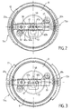
- La figure 2 montre, selon une vue de dessus, un récipient de cuisson pourvu du dispositif de commande selon l'invention, dans lequel les mâchoires sont en position de verrouillage.
- La figure 3 montre, selon une vue de dessus identique à celle de la figure 2, le dispositif de commande conforme à l'invention, les mâchoires étant en position de déverrouillage.
- La figure 4 montre, selon une vue en coupe partielle, un détail du dispositif de commande conforme à l'invention.
- Figure 1 shows, in a general cross-sectional view, the upper part of a cooking container provided with the control device according to the invention.
- Figure 2 shows, in a top view, a cooking container provided with the control device according to the invention, in which the jaws are in the locked position.
- Figure 3 shows, in a top view identical to that of Figure 2, the control device according to the invention, the jaws being in the unlocked position.
- Figure 4 shows, in a partial sectional view, a detail of the control device according to the invention.
Le dispositif de verrouillage/déverrouillage conforme à l'invention est destiné à assurer la fermeture par verrouillage d'un couvercle 1 sur une cuve 2 de manière à former un récipient de cuisson, de préférence sous pression tel qu'un autocuiseur. Le récipient est par exemple constitué d'une cuve de forme sensiblement cylindrique, d'axe de révolution x-x', sur laquelle le couvercle 1 est destiné à être rapporté de manière étanche, par exemple par l'intermédiaire d'un joint d'étanchéité à lèvres 3.The locking / unlocking device according to the invention is intended to ensure the closing by locking of a cover 1 on a tank 2 so as to form a cooking container, preferably under pressure such as a pressure cooker. The container consists for example of a tank of substantially cylindrical shape, of axis of revolution x-x ', on which the cover 1 is intended to be attached in leaktight manner, for example by means of a gasket seal 3.
La cuve 2 est de manière classique réalisée à partir d'un matériau métallique tel que de l'inox et pourvu d'un fond thermoconducteur solidaire de la cuve 2, par exemple par frappe à chaud. La cuve comporte également des organes de préhension tels que des poignées 5 fixées sur les parois de la cuve 2 par l'intermédiaire de pattes d'attaches 6 et de vis 7.The tank 2 is conventionally made from a metallic material such as stainless steel and provided with a thermally conductive bottom secured to the tank 2, for example by hot stamping. The tank also includes gripping members such as handles 5 fixed to the walls of the tank 2 by means of fastening tabs 6 and screws 7.
Le couvercle 1 comporte un disque de fermeture 8 profilé, pourvu à sa périphérie d'une zone en forme de gorge 9 servant de siège de réception du joint d'étanchéité à lèvres 3, et assumant avec ce dernier l'étanchéité de la fermeture du couvercle 1.The cover 1 comprises a profiled
Le disque de fermeture 8 est pourvu d'au moins un perçage permettant le passage et le montage d'une soupape de verrouillage 10 montée à coulissement libre axial dans ledit perçage entre une position basse de butée (telle que montrée à la figure 1 par exemple), et une position haute de butée.
La soupape de verrouillage 10 peut être constituée tel que cela est bien connu dans l'art antérieur d'un doigt de sécurité dont la fonction principale est de fournir une information visuelle de la pression régnant dans le récipient sous pression.The
The
Avantageusement l'étanchéité à la vapeur, entre la soupape de verrouillage 10 et le perçage est améliorée par interposition d'un joint 11, ce dernier étant maintenu en position par appui sur une collerette 12 formant la partie radiale externe inférieure de la soupape de verrouillage 10.Advantageously, the vapor tightness between the
Le couvercle 1 comporte également au moins deux mâchoires 15a, 15b, montées radialement mobiles sur le disque de fermeture 8 entre une position de verrouillage du couvercle 1 sur la cuve 2 (figures 1 et 2) et une position de déverrouillage (figure 3). Les mâchoires 15a, 15b, se présentent de manière classique sous la forme de segments de profils en U adaptés à la forme du récipient, et dans le cas montré aux figures, sous la forme d'arcs de cercles de longueur déterminée. Chaque mâchoire 15 comporte un rebord inférieur 16 et un rebord supérieur 17 permettant d'enserrer respectivement le rebord périphérique 2a de la cuve 2 et la limite supérieure de la gorge 9. Chaque mâchoire 15a, 15b, est montée mobile sur le couvercle par l'intermédiaire d'éléments entraîneurs incluant des bras entraîneurs associés 20a, 20b, diamétralement opposés et solidaires par une extrémité 21, par exemple par soudage, du rebord supérieur 17. Dans la version préférentielle de l'invention montrée aux figures 1 à 4, chaque bras entraîneur 20a, 20b, se présente sous la forme d'un profilé métallique par exemple rectiligne, de profil adapté à celui du disque de fermeture 8 et de section transversale en U, dont l'âme est tournée vers l'extérieur du récipient et dont les ailes 22 s'étendent également vers l'extérieur du récipient.The cover 1 also comprises at least two
Selon une version préférentielle de l'invention, les bras entraîneurs 20a, 20b, présentent une longueur suffisante de manière à pouvoir être superposés, au moins en partie, lors de leur déplacement radial. Selon cette variante les bras entraîneurs 20a, 20b, sont autoguidés radialement l'un dans l'autre, le bras 20a formant le bras mâle et le 20b formant le bras femelle, le bras mâle coulissant dans le bras femelle. Le guidage relatif des bras 20a, 20b, est obtenu par coopération et frottement des ailes 22 de chacun des bras 20a, 20b. Un tel montage permet bien évidemment de réduire les risques de déformation possible lors du coulissement radial de chacun des bras 20a, 20b, et de maîtriser parfaitement le déplacement linéaire de chaque mâchoire 15a, 15b.According to a preferred version of the invention, the
Selon cette version préférentielle de l'invention, chaque bras entraîneur, 20a, 20b, est pourvu d'une lumière de verrouillage 25a, 25b, ménagée à travers l'âme de chaque bras. La position de chaque lumière 25a, 25b est déterminée en fonction de la longueur de chaque bras 20a, 20b pour que les lumières 25a, 25b soient en position d'alignement lorsque les mâchoires 15a, 15b, sont en position de verrouillage. Simultanément la position des lumières 25a, 25b, ainsi que la position du perçage, et donc de la soupape 10, est choisie pour que lorsque les mâchoires 15a et 15b sont en position de verrouillage, les lumières 25a, 25b, ainsi que le perçage soient alignés. Cette disposition permet à la soupape de verrouillage 10 d'occuper la position déterminée correspondant à la pression régnant dans le récipient, et en particulier d'occuper sa position haute dans laquelle la soupape 10 s'engage chacune des lumières 25a, 25b, pour verrouiller les mâchoires dans leur position de verrouillage. Une telle position n'est bien évidemment acquise que lorsque les mâchoires 15a, 15b, occupent avec précision leur position de verrouillage qui seule permet le passage de la soupape 10 simultanément dans les lumières 25a, 25b. Dans le cas où l'alignement des lumières 25a, 25b n'est pas obtenu lors de la tentative de fermeture, la soupape de verrouillage 10 ne peut monter ce qui génère une fuite de vapeur hors du récipient empêchant toute montée en pression.According to this preferred version of the invention, each driving arm, 20a, 20b, is provided with a locking lumen 25a, 25b, formed through the core of each arm. The position of each lumen 25a, 25b is determined as a function of the length of each
Avantageusement, le guidage du mouvement linéaire et radial des bras entraîneurs 20a, 20b, est assuré par des moyens de guidage supplémentaires qui sont solidaires du couvercle 1.Advantageously, the guiding of the linear and radial movement of the driving
Selon une variante préférentielle de l'invention, les moyens de guidage sont formés par une pièce de support 30 qui enserre les bras entraîneurs 20a, 20b, sur la majeure partie de leur longueur.According to a preferred variant of the invention, the guide means are formed by a
Selon une version préférentielle de l'invention, la pièce support 30 est formée d'une plaque de section transversale en U enserrant et recouvrant les bras entraîneurs 20a, 20b, la face interne de l'âme du U étant tournée vers le disque de fermeture 8. La plaque support 30 est avantageusement solidaire du disque de fermeture 8 par l'intermédiaire de deux points d'ancrage 31, 32, situés de part et d'autre de l'axe longitudinal de la plaque support 30. Les points d'ancrage 31, 32, peuvent être constitués de moyens de fixations tels que des vis, ou au contraire également servir de siège pour le passage de moyens de régulation de la pression.According to a preferred version of the invention, the
A titre de variante il est également possible de monter la plaque de support 30 de manière inversée, la face interne de la plaque support 30 étant tournée vers l'extérieur du récipient, les bras 20a, 20b, coulissant l'un dans l'autre ainsi que dans ladite plaque support. Dans cette position, la plaque support 30 enserre et supporte les bras 20a,20b.As a variant, it is also possible to mount the
Selon une autre variante de réalisation, les moyens de guidage peuvent être constitués de rampes ou de moyens équivalents, solidaires ou partie intégrante du disque de fermeture 8.According to another alternative embodiment, the guide means may consist of ramps or equivalent means, integral with or integral with the
Dans tous les cas, et en particulier dans le cas où une plaque support 30, présentant un profil en U est utilisée, les moyens de guidage assument, outre une fonction d'aide supplémentaire au coulissement linéaire des bras entraîneurs 20a, 20b, une fonction complémentaire de rigidification de l'ensemble mécanique assurant le déplacement radial des mâchoires 15a, 15b.In all cases, and in particular in the case where a
La course de déplacement des bras entraîneurs 20a, 20b, entre chacune de leur position limite, correspondant à la position d'ouverture et de fermeture des mâchoires 15a, 15b, est limitée par l'intermédiaire d'une fente 40, ménagée de préférence dans le bras mâle 20a, dans laquelle peut se déplacer un ergot 41 solidaire du bras femelle 20b. La course de déplacement des bras 20a, 20b, est ainsi limitée par la mise en butée de l'ergot 41 contre l'une ou l'autre des deux extrémités de la fente 40.The displacement travel of the driving
Selon un mode de réalisation particulier la plaque support 30 comporte une ouverture alignée avec les lumières 25a, 25b, ainsi qu'avec le perçage, permettant le montage en suspension de la soupape de verrouillage 10, par sa partie supérieure de section réduite par rapport à la partie inférieure de la soupape de verrouillage 10. Un tel montage permet le coulissement relatif des bras entraîneurs 20a, 20b, lorsque la soupape de verrouillage 10 est dans sa position basse, ce qui assure simultanément le libre déplacement des mâchoires 15a, 15b.According to a particular embodiment, the
Avantageusement les bras entraîneurs 20a, 20b, sont ramenés en permanence en position de verrouillage par un moyen de rappel élastique constitué par exemple d'un ressort 45 interposé entre deux jambages respectivement solidaires de chacun des bras entraîneurs 20a, 20b.Advantageously, the driving
Le dispositif de verrouillage/déverrouillage conforme à l'invention comporte également un moyen de commande 50 du mouvement des mâchoires 15a, 15b, permettant d'amener chaque mâchoire dans l'une ou l'autre de leur position fixe de verrouillage/déverrouillage.The locking / unlocking device according to the invention also comprises a
Selon une version préférentielle de l'invention telle que montrée à la figure 4, le moyen de commande 50 forme l'organe de préhension du couvercle 1 et est constitué d'un organe de commande 56 monté mobile selon une direction sensiblement radiale sur le couvercle 1 et couplé cinématiquement avec un bouton de commande 52 monté mobile sur le couvercle 1 selon une direction sensiblement axiale.According to a preferred version of the invention as shown in Figure 4, the control means 50 forms the gripping member of the cover 1 and consists of a
Le moyen de commande 50 est constitué d'un pommeau 51 solidaire du couvercle 1, et du bouton de commande 52 monté mobile axialement et élastiquement par un ressort de rappel 52a dans le pommeau 52. Le ressort de rappel 52a maintient le bouton de commande 52 dans la position haute montrée à la figure 4. Le bouton de commande 52 comporte à sa partie inférieure un doigt d'actionnement 53 pourvu d'une surface d'engagement inclinée 54 destinée à venir engager lors de l'enfoncement du bouton de commande 52 une surface d'engagement complémentaire 55 ménagée sur l'organe de commande 56. L'organe de commande 56 est monté sur le couvercle 1 selon une course déterminée de manière à être amené, lors de son déplacement entre les deux limites définissant sa course, à engager les bras entraîneurs 20a, 20b de façon à commander leur déplacement radial.The control means 50 consists of a
Selon une version préférentielle de l'invention l'organe de commande 56 assure le déplacement radial des bras entraîneurs 20a, 20b, de manière active dans le sens radial externe c'est-à-dire dans un sens correspondant à l'écartement progressif des mâchoires 15a, 15b pour atteindre leur position extrême de déverrouillage. Selon cette version préférentielle de l'invention, l'organe de commande 56 est couplé cinématiquement avec le bouton de commande 52 dont le déplacement selon la direction sensiblement axiale définie précédemment, commande le déplacement des bras entraîneurs 20a, 20b, dans le sens radial interne, c'est-à-dire dans un sens de déplacement des mâchoires en direction de leur position de verrouillage. A cette fin l'organe de commande 56 est formé par un poussoir monté sous le pommeau 51. Le poussoir 56 présente une zone de commande 57 surélevée et accessible manuellement par l'utilisateur, ainsi qu'une zone triangulaire 58 d'actionnement plane apte à venir engager des moyens d'actionnement solidaires des bras entraîneurs 20a, 20b.According to a preferred version of the invention, the
Selon une variante préférentielle de l'invention, les moyens d'actionnement sont constitués par l'ergot 41 et par un ergot 41 b homologue, solidaire du bras entraîneur 20b. Le déplacement de la zone triangulaire 58 selon une direction radiale à double sens permet ainsi de déplacer également radialement les ergots 41, 41 b mais selon une direction orientée à 90° par rapport à la direction de déplacement du poussoir 56. Par le biais de la zone triangulaire 58, le poussoir 56 engage par conséquent de manière active les bras entraîneurs 20a, 20b et assure progressivement leur écartement lorsque l'utilisateur appuie sur la zone de commande 57. Lorsque les moyens de guidage sont formés par une plaque support 30 recouvrant les bras entraîneurs 20a, 20b, la plaque support 30 comporte deux ouvertures 40a, 40b, ménagées dans l'âme de ladite plaque, et destinées au passage, respectivement des ergots 41, 41b, pour permettre leur déplacement radial. Les ouvertures 40a, 40b ont pour fonction secondaire de limiter la course de déplacement individuel de chaque bras 20a, 20b en servant de butée aux ergots 41, 41b, évitant ainsi le désengagement des mâchoires 15a, 15b hors du couvercle 1.According to a preferred variant of the invention, the actuation means are constituted by the
Avantageusement, la zone d'actionnement triangulaire 58 comporte deux évidements 60a, 60b, par exemple semi-circulaires, et dans tous les cas de forme complémentaire à celle des ergots 41, 41b, de manière à déterminer une position stable et fixe d'ouverture des mâchoires correspondant à un blocage en position desdits ergots dans les évidements correspondants 60a, 60b.Advantageously, the
Lors de l'enfoncement du bouton de commande 52 le doigt d'actionnement 53, lorsque les mâchoires 15a, 15b sont en position de déverrouillage, vient engager la surface d'engagement complémentaire 55 pour commander le désarmement du poussoir 56. Le désarmement correspond à une sortie des ergots 41, 41 b hors des évidements 60a, 60b, le doigt d'actionnement 53 formant ainsi des moyens de relâchement alors que les évidements 60a, 60b forment des moyens de blocage.When the
Selon la version préférentielle de l'invention montrée aux figures 1 à 4, l'organe de commande 56 et le bouton de commande 52 sont montés sur le couvercle en position centrale pour former un ensemble de préhension du couvercle.According to the preferred version of the invention shown in Figures 1 to 4, the
A titre de variante il est bien évidemment possible de dissocier l'ensemble de préhension du couvercle, de l'organe de commande 56 et du bouton de commande 52.As a variant, it is obviously possible to dissociate the gripping assembly from the cover, from the
A titre de variante complémentaire il est bien évidemment également possible, sans sortir du cadre de l'invention, de réaliser un dispositif de commande comportant un seul organe de commande 56 capable d'assurer à lui seul la commande dans les deux sens du déplacement radial des bras entraîneurs 20a, 20b. Selon cette variante l'organe de commande 56 assure le déplacement des bras entraîneurs 20a, 20b de manière active dans le sens radial externe et dans le sens radial interne défini précédemment. L'organe de commande 56 est alors constitué d'un simple bouton poussoir dont le profil permet à l'utilisateur par simple poussée ou tirage d'assurer l'écartement ou la rétraction des mâchoires 15a, 15b.By way of a complementary variant, it is obviously also possible, without departing from the scope of the invention, to produce a control device comprising a
Le couvercle 1 peut compter une plaque d'habillage 65 recouvrant l'ensemble du mécanisme, ladite plaque étant prise en sandwich entre la plaque support 30 et le pommeau 51.The cover 1 can have a covering
Le fonctionnement du dispositif verrouillage/ déverrouillage conforme à l'invention est le suivant.The operation of the locking / unlocking device according to the invention is as follows.
La mise en place du couvercle 1 sur la cuve 2 nécessite l'ouverture des mâchoires 15a, 15b, et l'actionnement radial du poussoir 56 ce qui permet de faire coulisser la zone d'actionnement triangulaire 58 qui vient progressivement engager par ses flancs les ergots 41, 41b (figure 2). Le déplacement progressif du poussoir 56 permet d'écarter progressivement les bras entraîneurs 20a, 20b, et simultanément les mâchoires 15a, 15b. La translation du poussoir 56 selon une direction radiale permet donc la translation des deux mâchoires 15a, 15b selon une direction également radiale, mais perpendiculaire à la direction du déplacement du poussoir 56. La fin de la translation est déterminée par le positionnement de chaque ergot 41, 41b, dans les évidements associés 60a, 60b (figure 2). Au delà de cette translation la position limite des mâchoires 15a, 15b est également déterminée par la mise en butée de l'ergot 41 contre l'extrémité de la fente 40. Dans la position ainsi atteinte, les mâchoires 15a, 15b, sont en position stable de déverrouillage et permettent ainsi un centrage du couvercle 1 sur le bord de la cuve 2.The introduction of the cover 1 on the tank 2 requires the opening of the
La fermeture du récipient, c'est-à-dire l'atteinte par les mâchoires 15a, 15b, de leur position de verrouillage, est obtenue par pression de la paume de la main sur le bouton de pommeau 52 qui est par conséquent actionné axialement. Son enfoncement dans le pommeau 51 provoque l'engagement de la surface d'engagement 54 avec sa surface complémentaire 55 ménagée sur le bouton poussoir 56, lequel va progressivement reculer selon une direction radiale externe. Au cours de cette translation en sens inverse, les ergots 41, 41b, sont tout d'abord libérés des évidements 60a, 60b, les mâchoires 15a, 15b, étant ensuite progressivement rappelées l'une vers l'autre vers leur position de verrouillage (figures 2 et 4). Le rappel vers cette position de verrouillage est obtenu par l'action de rappel du ressort 45 permettant le positionnement de chaque mâchoire 15a, 15b, entre le couvercle 1 et sous le rebord 2a de la cuve 2.The closure of the container, that is to say the
Le récipient étant ainsi fermé de manière étanche, la pression peut désormais monter et provoquer le passage de la soupape de verrouillage 10 dans sa position haute à travers les lumières 25a, 25b, lesquelles en position de fermeture complète des mâchoires 15a, 15b, sont coaxiales. L'engagement de la soupape de verrouillage 10 à travers les lumières 25a, 25b permet de verrouiller en position chacun des bras entraîneurs 20a, 20b, et simultanément chaque mâchoire correspondante.The container being thus sealed, the pressure can now rise and cause the passage of the locking
Le dispositif de verrouillage/déverrouillage conforme à l'invention permet ainsi d'assurer une montée en pression en toute sécurité puisque le passage de la soupape de verrouillage dans les lumières de verrouillage 25a, 25b, ne peut intervenir que si les bras d'entraînement 20a, 20b, et donc les mâchoires 15a, 15b, sont en position de verrouillage parfaite. La soupape de verrouillage 10 s'oppose par ailleurs à tout déplacement radial des mâchoires 15a, 15b. Le déplacement radial et linéaire des bras entraîneurs 15a, 15b, est par ailleurs obtenu sans risque de déformation en raison de la présence d'une succession de moyens de guidage formés par le coulissement des bras intérieurs l'un à l'autre et par la plaque support 30.The locking / unlocking device according to the invention thus makes it possible to ensure a pressure increase in complete safety since the passage of the locking valve in the locking slots 25a, 25b, can only intervene if the
A titre de variante complémentaire, il est évidemment possible d'avoir recours à des bras entraîneurs 20a, 20b qui ne sont pas montés relativement l'un par rapport à l'autre en position de chevauchement, le verrouillage étant obtenu à l'aide d'une soupape de verrouillage 10 associée à chacun des bras entraîneurs 25a, 25b.As a further variant, it is obviously possible to have recourse to driving
La dissociation de la gestuelle nécessaire au verrouillage des mâchoires 15a, 15b (action de poussée axiale ou tirage radial), de celle nécessaire au déverrouillage (action de poussée radiale), évite, grâce à sa mémorisation naturelle, les erreurs de manipulation.The dissociation of the gestures necessary for locking the
Claims (10)
caractérisé en ce qu'il comporte un organe de commande (56) monté mobile selon une direction sensiblement radiale sur le couvercle (1) et selon une course déterminée, ledit organe (56) étant amené, lors de son déplacement, à engager les bras entraîneurs (20a, 20b) de façon à commander leur déplacement radial.Device for controlling the opening and closing of jaws (15a, 15b) mounted to move radially on a cover (1) by driving arms (20a, 20b), said jaws (15a, 15b) being intended to ensure locking the cover (1) on a tank (2) to close a cooking container, preferably under pressure,
characterized in that it comprises a control member (56) mounted movable in a substantially radial direction on the cover (1) and according to a determined stroke, said member (56) being caused, during its movement, to engage the arms coaches (20a, 20b) so as to control their radial movement.
Applications Claiming Priority (2)
| Application Number | Priority Date | Filing Date | Title |
|---|---|---|---|
| FR9408585A FR2722078B1 (en) | 1994-07-06 | 1994-07-06 | DEVICE FOR CONTROLLING THE OPENING AND CLOSING OF LOCKING JAWS FOR A PRESSURE CONTAINER |
| FR9408585 | 1994-07-06 |
Publications (2)
| Publication Number | Publication Date |
|---|---|
| EP0691097A1 true EP0691097A1 (en) | 1996-01-10 |
| EP0691097B1 EP0691097B1 (en) | 1997-08-13 |
Family
ID=9465260
Family Applications (1)
| Application Number | Title | Priority Date | Filing Date |
|---|---|---|---|
| EP95420188A Expired - Lifetime EP0691097B1 (en) | 1994-07-06 | 1995-07-05 | Device for controlling the opening and closing of the locking clamps on a pressure vessel |
Country Status (20)
| Country | Link |
|---|---|
| US (1) | US5613424A (en) |
| EP (1) | EP0691097B1 (en) |
| JP (1) | JP3073668B2 (en) |
| KR (1) | KR100202162B1 (en) |
| CN (1) | CN1041274C (en) |
| AT (1) | ATE156678T1 (en) |
| BR (1) | BR9503074A (en) |
| CA (1) | CA2153194C (en) |
| CZ (1) | CZ290995B6 (en) |
| DE (2) | DE69500549T2 (en) |
| ES (1) | ES2107900T3 (en) |
| FR (1) | FR2722078B1 (en) |
| GR (1) | GR3025031T3 (en) |
| HU (1) | HU216887B (en) |
| MA (1) | MA23835A1 (en) |
| PL (1) | PL179152B1 (en) |
| RO (1) | RO116860B1 (en) |
| RU (1) | RU2126224C1 (en) |
| TR (1) | TR199500828A2 (en) |
| WO (1) | WO1996001070A1 (en) |
Cited By (4)
| Publication number | Priority date | Publication date | Assignee | Title |
|---|---|---|---|---|
| FR2833476A1 (en) | 2001-12-19 | 2003-06-20 | Seb Sa | Pressure cooker lid comprises U-section jaw with upper bearing surface, front face and lower face in contact and under cooking tank edge when locked, and central release |
| EP2201870A1 (en) | 2008-12-30 | 2010-06-30 | Seb S.A. | Pressure-cooking device with lightened jaws and manufacturing method |
| EP3100657A1 (en) | 2015-06-04 | 2016-12-07 | Seb S.A. | Pressure cooker provided with a detachable valve and a temperature sensor |
| EP3100656A1 (en) | 2015-06-04 | 2016-12-07 | Seb S.A. | Pressure cooker equipped with a support and a lid which is movable with respect to said support |
Families Citing this family (42)
| Publication number | Priority date | Publication date | Assignee | Title |
|---|---|---|---|---|
| FI98810C (en) * | 1994-09-15 | 1997-08-25 | Nerox Filter Oy | Water treatment device |
| KR0132659Y1 (en) * | 1995-11-29 | 1998-12-01 | 이원명 | Cooking pan |
| KR0128775Y1 (en) * | 1995-12-07 | 1998-10-15 | 문무영 | Locking instrument of cover for electric pressure cooker |
| US5839357A (en) * | 1996-03-15 | 1998-11-24 | Samsung Electronics Co., Ltd. | Electric pressure cooker |
| FR2754696B1 (en) * | 1996-10-21 | 1999-08-06 | Moulinex Sa | ELECTRIC COOKING APPLIANCE COMPRISING A DEVICE FOR CONDENSING COOKING VAPORS |
| FR2769200B1 (en) * | 1997-10-03 | 1999-11-19 | Seb Sa | HOUSEHOLD HOUSEHOLD APPLIANCE FOR FOOD PREPARATION, COMPRISING A SIMPLIFIED LOCKING DEVICE |
| EP1018918B1 (en) * | 1997-10-03 | 2003-07-16 | Seb S.A. | Household electric cooking appliance, such as a food processor, comprising a simplified locking and unlocking device |
| US6123373A (en) * | 1997-10-30 | 2000-09-26 | Teac Corporation | Lock device having an improved lock member |
| ES2171337B1 (en) * | 1998-11-13 | 2003-06-16 | Fagor S Coop | EXPRESSED POT WITH LOCK OF THE CLOSURE OF THE COVER. |
| FR2786383B1 (en) | 1998-11-26 | 2001-01-26 | Seb Sa | MECHANISM FOR FIXING A SOLIDARITY COVER OF THE MOTOR OF A HOUSEHOLD ROBOT ON A WORKING CONTAINER |
| ES1041853Y (en) * | 1998-12-07 | 2000-01-01 | Fagor S Coop | POT EXPRESS WITH SECURITY AGAINST THE TURN OF THE LID. |
| EP1201166A4 (en) * | 1999-07-21 | 2003-01-08 | Ono Foods Ind Co Ltd | Heat cooking/sterilizing device |
| DE10014766C2 (en) | 2000-03-27 | 2002-02-21 | Ursula Niese | Steam pressure cooker |
| AU2001248721A1 (en) * | 2000-04-07 | 2001-10-23 | Jian, Wei Wen | Pressure cooker |
| TW429766U (en) * | 2000-05-22 | 2001-04-11 | Chen Jin Tsai | Improved pressure pot |
| JP4083679B2 (en) * | 2001-07-26 | 2008-04-30 | コーニンクレッカ フィリップス エレクトロニクス エヌ ヴィ | Equipment for frying food |
| WO2003013323A1 (en) * | 2001-08-09 | 2003-02-20 | Jong Peter Park | Device for coupling a lid to pot |
| DE20113356U1 (en) | 2001-08-10 | 2002-12-19 | Synkrona Ag Stans | Closing device for a container |
| DE20201624U1 (en) | 2002-02-01 | 2003-06-18 | Synkrona Ag Stans | Closing device for a container |
| FR2836807B1 (en) * | 2002-03-08 | 2004-07-16 | Seb Sa | PRESSURIZED FOOD COOKING APPLIANCE WITH ROTARY LOCK / RELEASE CONTROL DEVICE |
| US6513420B1 (en) * | 2002-04-12 | 2003-02-04 | Jong Peter Park | Device for coupling a lid to pot |
| KR100487064B1 (en) * | 2002-11-13 | 2005-05-03 | 임필권 | Opening/Shutting device for lid of pressure cooker |
| FR2862854B1 (en) * | 2003-11-27 | 2006-09-15 | Seb Sa | PRESSURIZED COOKING CONTAINER COMPRISING A CONTROLLED DEFORMATION COVERING LID AND CORRESPONDING COVER |
| FR2863849B1 (en) | 2003-12-23 | 2006-11-10 | Seb Sa | DOMESTIC PRESSURIZED FOOD COOKING APPARATUS WITH IMPROVED LATCHING DEVICE |
| KR200353218Y1 (en) * | 2004-02-05 | 2004-06-22 | 이동우 | Push-type lid of pressure cooker |
| KR20040065537A (en) * | 2004-06-28 | 2004-07-22 | 윤장식 | a pressure rice cooker having an instant kimchi manufacturing function |
| FR2874805B1 (en) * | 2004-09-09 | 2008-05-23 | Seb Sa | OPTIMIZED DECOMPRESSION COOKING UNDER PRESSURE COOKER |
| DE102004056463B3 (en) * | 2004-11-23 | 2006-03-16 | Gero Vertriebs Gmbh | cooking vessel |
| KR100907818B1 (en) | 2006-06-08 | 2009-07-16 | 주식회사 엘지화학 | An integrated O-film for improving the TN-LCD viewing angle, a polarizing plate laminate containing the same, and a TN-LCD |
| FR2918862B1 (en) * | 2007-07-20 | 2009-10-09 | Seb Sa | COOKER WITH AN INFORMATION WINDOW |
| US8230779B2 (en) * | 2008-10-14 | 2012-07-31 | Hamilton Beach Brands, Inc. | Deep fryer for cooking foodstuff |
| FR2940601B1 (en) * | 2008-12-30 | 2012-07-13 | Seb Sa | PRESSURIZED COOKING APPARATUS WITH BI-FUNCTIONAL LOCKING / UNLOCKING CONTROL MEMBER |
| FR2993157B1 (en) * | 2012-07-16 | 2016-07-01 | Seb Sa | PRESSURIZED FOOD COOKING APPARATUS WITH IMPROVED CONTROL DEVICE |
| JP6049131B2 (en) * | 2012-08-29 | 2016-12-21 | 勝文 青柳 | Pressure cooker |
| TWI549635B (en) * | 2013-02-22 | 2016-09-21 | 御鼎節能科技股份有限公司 | Pot |
| WO2015074112A1 (en) * | 2013-11-21 | 2015-05-28 | Meyer Intellectual Properties Limited | Microwave pressure cooker |
| WO2016050438A1 (en) | 2014-10-02 | 2016-04-07 | Arcelik Anonim Sirketi | A food preparation appliance |
| FR3036934B1 (en) | 2015-06-02 | 2017-07-14 | Seb Sa | AUTOCUIZER HAVING A MANUAL LOCK CONTROL MEMBER |
| US20180002648A1 (en) * | 2016-06-01 | 2018-01-04 | Colorado Brewing Systems, LLC | Electric Brewing System |
| RU2689215C2 (en) * | 2017-10-10 | 2019-05-24 | Сергей Сергеевич Ершов | Device for fixation of lid on dishware |
| CN112006547B (en) * | 2019-05-31 | 2022-04-22 | 佛山市顺德区美的电热电器制造有限公司 | Upper cover assembly of cooking utensil and cooking utensil |
| GB2606580A (en) * | 2021-05-14 | 2022-11-16 | Kenwood Ltd | Food processor lid |
Citations (5)
| Publication number | Priority date | Publication date | Assignee | Title |
|---|---|---|---|---|
| DE3232907A1 (en) * | 1982-09-04 | 1984-03-08 | Boehm, Hans-Georg, Dipl.-Phys. Dr.rer.nat, 6242 Kronberg | STEAM PRESSURE COOKER |
| DE3327439A1 (en) * | 1983-07-29 | 1985-02-07 | Württembergische Metallwarenfabrik AG, 7340 Geislingen | Lid for a pressure cooker |
| EP0139772A1 (en) * | 1983-08-25 | 1985-05-08 | AMC International Alfa Metalcraft Corporation AG | Pressure cooker |
| WO1992003080A1 (en) | 1990-08-17 | 1992-03-05 | Amc International Alfa Metalcraft Corporation Ag | Cooking vessel |
| EP0491324A1 (en) * | 1990-12-18 | 1992-06-24 | SILIT-WERKE GMBH & CO. KG | Lid for a cooking vessel with an inwardly curved external edge |
Family Cites Families (8)
| Publication number | Priority date | Publication date | Assignee | Title |
|---|---|---|---|---|
| IT8123053V0 (en) * | 1981-09-28 | 1981-09-28 | Ind Sambonet S R L | PRESSURE COOKER FOR COOKING IN WATER OR STEAM. |
| FR2531847A1 (en) * | 1982-08-20 | 1984-02-24 | Seb Sa | DEVICE FOR CLOSING A COVER ON A PRESSURIZED COOKING CONTAINER |
| KR0181712B1 (en) * | 1990-05-26 | 1999-03-20 | 호르스트 슐츠 | Cooking pot with improved locking structure |
| DE4133524C2 (en) * | 1991-10-10 | 1996-08-29 | Fissler Gmbh | Pressure cooker |
| IT222094Z2 (en) * | 1991-12-12 | 1994-12-30 | Aeternum Srl | CLOSING AND SAFETY DEVICE IN A PRESSURE COOKER |
| CH684927A5 (en) * | 1992-12-04 | 1995-02-15 | Amc Int Alfa Metalcraft Corp | Cooking vessel. |
| FR2700825B1 (en) * | 1993-01-28 | 1995-04-14 | Seb Sa | Device for automatic control of a flow limitation valve. |
| FR2701370B1 (en) * | 1993-02-15 | 1995-04-21 | Seb Sa | Locking-unlocking device with jaws of a cover on a tank. |
-
1994
- 1994-07-06 FR FR9408585A patent/FR2722078B1/en not_active Expired - Lifetime
-
1995
- 1995-07-03 MA MA23943A patent/MA23835A1/en unknown
- 1995-07-04 CA CA002153194A patent/CA2153194C/en not_active Expired - Lifetime
- 1995-07-04 BR BR9503074A patent/BR9503074A/en not_active IP Right Cessation
- 1995-07-05 RU RU96106902A patent/RU2126224C1/en active
- 1995-07-05 CZ CZ19961001A patent/CZ290995B6/en not_active IP Right Cessation
- 1995-07-05 RO RO96-00443A patent/RO116860B1/en unknown
- 1995-07-05 EP EP95420188A patent/EP0691097B1/en not_active Expired - Lifetime
- 1995-07-05 CN CN95109146A patent/CN1041274C/en not_active Expired - Lifetime
- 1995-07-05 PL PL95313286A patent/PL179152B1/en unknown
- 1995-07-05 WO PCT/FR1995/000897 patent/WO1996001070A1/en active IP Right Grant
- 1995-07-05 ES ES95420188T patent/ES2107900T3/en not_active Expired - Lifetime
- 1995-07-05 DE DE69500549T patent/DE69500549T2/en not_active Expired - Lifetime
- 1995-07-05 HU HU9600511A patent/HU216887B/en unknown
- 1995-07-05 AT AT95420188T patent/ATE156678T1/en active
- 1995-07-06 DE DE29510989U patent/DE29510989U1/en not_active Expired - Lifetime
- 1995-07-06 TR TR95/00828A patent/TR199500828A2/en unknown
- 1995-07-06 JP JP07171193A patent/JP3073668B2/en not_active Expired - Lifetime
- 1995-07-06 US US08/499,249 patent/US5613424A/en not_active Expired - Lifetime
- 1995-07-06 KR KR1019950019830A patent/KR100202162B1/en not_active IP Right Cessation
-
1997
- 1997-10-15 GR GR970402677T patent/GR3025031T3/en unknown
Patent Citations (5)
| Publication number | Priority date | Publication date | Assignee | Title |
|---|---|---|---|---|
| DE3232907A1 (en) * | 1982-09-04 | 1984-03-08 | Boehm, Hans-Georg, Dipl.-Phys. Dr.rer.nat, 6242 Kronberg | STEAM PRESSURE COOKER |
| DE3327439A1 (en) * | 1983-07-29 | 1985-02-07 | Württembergische Metallwarenfabrik AG, 7340 Geislingen | Lid for a pressure cooker |
| EP0139772A1 (en) * | 1983-08-25 | 1985-05-08 | AMC International Alfa Metalcraft Corporation AG | Pressure cooker |
| WO1992003080A1 (en) | 1990-08-17 | 1992-03-05 | Amc International Alfa Metalcraft Corporation Ag | Cooking vessel |
| EP0491324A1 (en) * | 1990-12-18 | 1992-06-24 | SILIT-WERKE GMBH & CO. KG | Lid for a cooking vessel with an inwardly curved external edge |
Cited By (9)
| Publication number | Priority date | Publication date | Assignee | Title |
|---|---|---|---|---|
| FR2833476A1 (en) | 2001-12-19 | 2003-06-20 | Seb Sa | Pressure cooker lid comprises U-section jaw with upper bearing surface, front face and lower face in contact and under cooking tank edge when locked, and central release |
| EP1321080A2 (en) | 2001-12-19 | 2003-06-25 | Seb S.A. | Cover for a pressure cooker with reduced jaws and pressure cooker with such a cover |
| WO2003051163A1 (en) | 2001-12-19 | 2003-06-26 | Seb S.A. | Lid for pressure cooking vessel with lightened jaws and cooking apparatus comprising |
| EP1321080A3 (en) * | 2001-12-19 | 2003-07-16 | Seb S.A. | Cover for a pressure cooker with reduced jaws and pressure cooker with such a cover |
| CN1313044C (en) * | 2001-12-19 | 2007-05-02 | 塞伯股份有限公司 | Lid for pressure cooking vessel with lightened jaws and cooking apparatus comprising |
| US7322279B2 (en) | 2001-12-19 | 2008-01-29 | Seb S.A. | Lid for pressure cooking vessel with lightened jaws and cooking apparatus comprising |
| EP2201870A1 (en) | 2008-12-30 | 2010-06-30 | Seb S.A. | Pressure-cooking device with lightened jaws and manufacturing method |
| EP3100657A1 (en) | 2015-06-04 | 2016-12-07 | Seb S.A. | Pressure cooker provided with a detachable valve and a temperature sensor |
| EP3100656A1 (en) | 2015-06-04 | 2016-12-07 | Seb S.A. | Pressure cooker equipped with a support and a lid which is movable with respect to said support |
Also Published As
| Publication number | Publication date |
|---|---|
| KR960003661A (en) | 1996-02-23 |
| CA2153194C (en) | 2002-05-07 |
| GR3025031T3 (en) | 1998-01-30 |
| PL179152B1 (en) | 2000-07-31 |
| HU216887B (en) | 1999-10-28 |
| ATE156678T1 (en) | 1997-08-15 |
| DE69500549D1 (en) | 1997-09-18 |
| CZ290995B6 (en) | 2002-11-13 |
| CN1041274C (en) | 1998-12-23 |
| JP3073668B2 (en) | 2000-08-07 |
| FR2722078B1 (en) | 1996-08-30 |
| RU2126224C1 (en) | 1999-02-20 |
| DE29510989U1 (en) | 1995-09-21 |
| CN1128848A (en) | 1996-08-14 |
| PL313286A1 (en) | 1996-06-24 |
| JPH0898766A (en) | 1996-04-16 |
| DE69500549T2 (en) | 1998-02-05 |
| US5613424A (en) | 1997-03-25 |
| EP0691097B1 (en) | 1997-08-13 |
| HUT74533A (en) | 1997-01-28 |
| TR199500828A2 (en) | 1996-06-21 |
| RO116860B1 (en) | 2001-07-30 |
| CA2153194A1 (en) | 1996-01-07 |
| BR9503074A (en) | 1996-06-11 |
| MA23835A1 (en) | 1996-12-31 |
| ES2107900T3 (en) | 1997-12-01 |
| WO1996001070A1 (en) | 1996-01-18 |
| FR2722078A1 (en) | 1996-01-12 |
| KR100202162B1 (en) | 1999-06-15 |
| HU9600511D0 (en) | 1996-04-29 |
| CZ100196A3 (en) | 1997-02-12 |
Similar Documents
| Publication | Publication Date | Title |
|---|---|---|
| EP0691097B1 (en) | Device for controlling the opening and closing of the locking clamps on a pressure vessel | |
| EP0691096B1 (en) | A locking/unlocking device with clamps for a lid on a vessel | |
| EP0611540B1 (en) | Lid locking device with ring segmented, claw clamps | |
| EP1547497B1 (en) | Domestic pressure cooking appliance with improved locking device | |
| EP1611824B1 (en) | Pressure cooker with lid having movable jaws | |
| EP1032295B1 (en) | Device for locking/unlocking a pressure cooker with lug-bayonet type closure | |
| EP1344476B1 (en) | Apparatus for cooking food under pressure with a rotative locking device | |
| EP1535553B1 (en) | Pressure cooker with unique actuation device for the decompression and the locking/unlocking | |
| CA2114200C (en) | Flow limiting valve automatic control device | |
| FR2514060A1 (en) | AUTOMATIC CLOSING LOCK WITH SWIVEL CLUTCH | |
| EP0981005A1 (en) | Coupling device for connecting a cartridge under pressure | |
| EP3586689A1 (en) | Pressure cooker provided with an abutment for a lid | |
| EP0037351A1 (en) | Multiple couplings for simultaneously joining several pneumatic or hydraulic pipes | |
| EP0711522B1 (en) | Valve for locking/unlocking a cover on a vessel | |
| EP1289394B1 (en) | Device for locking/unlocking a lid on a bowl and pressure cooker comprising same | |
| FR2816491A1 (en) | Locking/unlocking device for pressure cooker lid comprises four radially movable jaws connected by arms to movement control comprising control part and intermediate plate | |
| EP2702907B1 (en) | Lid of pressure cooking apparatus of simplified construction and pressure cooking apparatus with such lid. | |
| FR2936403A1 (en) | Removable handle for use with casserole, has upper and lower tabs respectively forming inner and outer support faces that are separated from each other along axis perpendicular to axis of grip, where tabs are integrated to grip | |
| EP4015741A1 (en) | System for gripping a key |
Legal Events
| Date | Code | Title | Description |
|---|---|---|---|
| PUAI | Public reference made under article 153(3) epc to a published international application that has entered the european phase |
Free format text: ORIGINAL CODE: 0009012 |
|
| 17P | Request for examination filed |
Effective date: 19950708 |
|
| AK | Designated contracting states |
Kind code of ref document: A1 Designated state(s): AT BE CH DE ES GB GR IT LI NL PT |
|
| 17Q | First examination report despatched |
Effective date: 19960401 |
|
| GRAG | Despatch of communication of intention to grant |
Free format text: ORIGINAL CODE: EPIDOS AGRA |
|
| GRAH | Despatch of communication of intention to grant a patent |
Free format text: ORIGINAL CODE: EPIDOS IGRA |
|
| GRAH | Despatch of communication of intention to grant a patent |
Free format text: ORIGINAL CODE: EPIDOS IGRA |
|
| GRAA | (expected) grant |
Free format text: ORIGINAL CODE: 0009210 |
|
| AK | Designated contracting states |
Kind code of ref document: B1 Designated state(s): AT BE CH DE ES GB GR IT LI NL PT |
|
| REF | Corresponds to: |
Ref document number: 156678 Country of ref document: AT Date of ref document: 19970815 Kind code of ref document: T |
|
| REG | Reference to a national code |
Ref country code: CH Ref legal event code: EP |
|
| REF | Corresponds to: |
Ref document number: 69500549 Country of ref document: DE Date of ref document: 19970918 |
|
| GBT | Gb: translation of ep patent filed (gb section 77(6)(a)/1977) |
Effective date: 19970917 |
|
| ITF | It: translation for a ep patent filed |
Owner name: ING. ZINI MARANESI & C. S.R.L. |
|
| REG | Reference to a national code |
Ref country code: CH Ref legal event code: NV Representative=s name: MOINAS KIEHL SAVOYE & CRONIN |
|
| REG | Reference to a national code |
Ref country code: ES Ref legal event code: FG2A Ref document number: 2107900 Country of ref document: ES Kind code of ref document: T3 |
|
| REG | Reference to a national code |
Ref country code: GR Ref legal event code: FG4A Free format text: 3025031 |
|
| REG | Reference to a national code |
Ref country code: PT Ref legal event code: SC4A Free format text: AVAILABILITY OF NATIONAL TRANSLATION Effective date: 19971017 |
|
| PLBE | No opposition filed within time limit |
Free format text: ORIGINAL CODE: 0009261 |
|
| STAA | Information on the status of an ep patent application or granted ep patent |
Free format text: STATUS: NO OPPOSITION FILED WITHIN TIME LIMIT |
|
| 26N | No opposition filed | ||
| REG | Reference to a national code |
Ref country code: GB Ref legal event code: IF02 |
|
| PGFP | Annual fee paid to national office [announced via postgrant information from national office to epo] |
Ref country code: PT Payment date: 20140619 Year of fee payment: 20 Ref country code: GR Payment date: 20140624 Year of fee payment: 20 |
|
| PGFP | Annual fee paid to national office [announced via postgrant information from national office to epo] |
Ref country code: DE Payment date: 20140711 Year of fee payment: 20 Ref country code: NL Payment date: 20140630 Year of fee payment: 20 Ref country code: CH Payment date: 20140715 Year of fee payment: 20 |
|
| PGFP | Annual fee paid to national office [announced via postgrant information from national office to epo] |
Ref country code: ES Payment date: 20140725 Year of fee payment: 20 Ref country code: GB Payment date: 20140717 Year of fee payment: 20 Ref country code: AT Payment date: 20140619 Year of fee payment: 20 |
|
| PGFP | Annual fee paid to national office [announced via postgrant information from national office to epo] |
Ref country code: IT Payment date: 20140714 Year of fee payment: 20 |
|
| PGFP | Annual fee paid to national office [announced via postgrant information from national office to epo] |
Ref country code: BE Payment date: 20140730 Year of fee payment: 20 |
|
| REG | Reference to a national code |
Ref country code: DE Ref legal event code: R071 Ref document number: 69500549 Country of ref document: DE |
|
| REG | Reference to a national code |
Ref country code: PT Ref legal event code: MM4A Free format text: MAXIMUM VALIDITY LIMIT REACHED Effective date: 20150705 |
|
| REG | Reference to a national code |
Ref country code: NL Ref legal event code: V4 Effective date: 20150705 Ref country code: CH Ref legal event code: PL |
|
| REG | Reference to a national code |
Ref country code: GB Ref legal event code: PE20 Expiry date: 20150704 |
|
| REG | Reference to a national code |
Ref country code: AT Ref legal event code: MK07 Ref document number: 156678 Country of ref document: AT Kind code of ref document: T Effective date: 20150705 |
|
| REG | Reference to a national code |
Ref country code: GR Ref legal event code: MA Ref document number: 970402677 Country of ref document: GR Effective date: 20150706 |
|
| REG | Reference to a national code |
Ref country code: ES Ref legal event code: FD2A Effective date: 20151026 |
|
| PG25 | Lapsed in a contracting state [announced via postgrant information from national office to epo] |
Ref country code: GB Free format text: LAPSE BECAUSE OF EXPIRATION OF PROTECTION Effective date: 20150704 Ref country code: PT Free format text: LAPSE BECAUSE OF EXPIRATION OF PROTECTION Effective date: 20150714 |
|
| PG25 | Lapsed in a contracting state [announced via postgrant information from national office to epo] |
Ref country code: ES Free format text: LAPSE BECAUSE OF EXPIRATION OF PROTECTION Effective date: 20150706 |