EP3586689A1 - Pressure cooker provided with an abutment for a lid - Google Patents
Pressure cooker provided with an abutment for a lid Download PDFInfo
- Publication number
- EP3586689A1 EP3586689A1 EP19182211.3A EP19182211A EP3586689A1 EP 3586689 A1 EP3586689 A1 EP 3586689A1 EP 19182211 A EP19182211 A EP 19182211A EP 3586689 A1 EP3586689 A1 EP 3586689A1
- Authority
- EP
- European Patent Office
- Prior art keywords
- tank
- cover
- configuration
- stop
- under pressure
- Prior art date
- Legal status (The legal status is an assumption and is not a legal conclusion. Google has not performed a legal analysis and makes no representation as to the accuracy of the status listed.)
- Granted
Links
- 238000010411 cooking Methods 0.000 claims abstract description 59
- 235000013305 food Nutrition 0.000 claims abstract description 36
- 229910052751 metal Inorganic materials 0.000 claims abstract description 36
- 239000002184 metal Substances 0.000 claims abstract description 36
- ZZUFCTLCJUWOSV-UHFFFAOYSA-N furosemide Chemical compound C1=C(Cl)C(S(=O)(=O)N)=CC(C(O)=O)=C1NCC1=CC=CO1 ZZUFCTLCJUWOSV-UHFFFAOYSA-N 0.000 claims description 9
- 230000000295 complement effect Effects 0.000 claims description 8
- 230000007704 transition Effects 0.000 claims description 8
- 230000001131 transforming effect Effects 0.000 claims description 3
- 230000008859 change Effects 0.000 claims description 2
- 230000003071 parasitic effect Effects 0.000 description 14
- 230000000694 effects Effects 0.000 description 10
- 230000009466 transformation Effects 0.000 description 10
- 239000004033 plastic Substances 0.000 description 8
- 238000006073 displacement reaction Methods 0.000 description 4
- 239000000463 material Substances 0.000 description 4
- 230000000284 resting effect Effects 0.000 description 4
- 229910052782 aluminium Inorganic materials 0.000 description 3
- XAGFODPZIPBFFR-UHFFFAOYSA-N aluminium Chemical compound [Al] XAGFODPZIPBFFR-UHFFFAOYSA-N 0.000 description 3
- 238000006243 chemical reaction Methods 0.000 description 3
- 239000007788 liquid Substances 0.000 description 3
- 230000007246 mechanism Effects 0.000 description 3
- 239000007769 metal material Substances 0.000 description 3
- 244000045947 parasite Species 0.000 description 3
- 229910001220 stainless steel Inorganic materials 0.000 description 3
- 239000010935 stainless steel Substances 0.000 description 3
- 230000002411 adverse Effects 0.000 description 2
- 238000010276 construction Methods 0.000 description 2
- 230000001276 controlling effect Effects 0.000 description 2
- 238000010438 heat treatment Methods 0.000 description 2
- 230000001105 regulatory effect Effects 0.000 description 2
- 238000000926 separation method Methods 0.000 description 2
- XLYOFNOQVPJJNP-UHFFFAOYSA-N water Substances O XLYOFNOQVPJJNP-UHFFFAOYSA-N 0.000 description 2
- KXGFMDJXCMQABM-UHFFFAOYSA-N 2-methoxy-6-methylphenol Chemical compound [CH]OC1=CC=CC([CH])=C1O KXGFMDJXCMQABM-UHFFFAOYSA-N 0.000 description 1
- 229920001342 Bakelite® Polymers 0.000 description 1
- -1 Bakelite® Chemical compound 0.000 description 1
- 241000287107 Passer Species 0.000 description 1
- 240000008042 Zea mays Species 0.000 description 1
- 229920001971 elastomer Polymers 0.000 description 1
- 239000000806 elastomer Substances 0.000 description 1
- 238000004519 manufacturing process Methods 0.000 description 1
- 229920001568 phenolic resin Polymers 0.000 description 1
- 230000001737 promoting effect Effects 0.000 description 1
- 238000007789 sealing Methods 0.000 description 1
- 241000894007 species Species 0.000 description 1
- 239000012815 thermoplastic material Substances 0.000 description 1
- 229920001187 thermosetting polymer Polymers 0.000 description 1
- 210000002105 tongue Anatomy 0.000 description 1
Images


Classifications
-
- A—HUMAN NECESSITIES
- A47—FURNITURE; DOMESTIC ARTICLES OR APPLIANCES; COFFEE MILLS; SPICE MILLS; SUCTION CLEANERS IN GENERAL
- A47J—KITCHEN EQUIPMENT; COFFEE MILLS; SPICE MILLS; APPARATUS FOR MAKING BEVERAGES
- A47J27/00—Cooking-vessels
- A47J27/08—Pressure-cookers; Lids or locking devices specially adapted therefor
- A47J27/0804—Locking devices
- A47J27/0806—Locking devices of the bayonet-type
-
- A—HUMAN NECESSITIES
- A47—FURNITURE; DOMESTIC ARTICLES OR APPLIANCES; COFFEE MILLS; SPICE MILLS; SUCTION CLEANERS IN GENERAL
- A47J—KITCHEN EQUIPMENT; COFFEE MILLS; SPICE MILLS; APPARATUS FOR MAKING BEVERAGES
- A47J27/00—Cooking-vessels
- A47J27/08—Pressure-cookers; Lids or locking devices specially adapted therefor
- A47J27/0804—Locking devices
-
- A—HUMAN NECESSITIES
- A47—FURNITURE; DOMESTIC ARTICLES OR APPLIANCES; COFFEE MILLS; SPICE MILLS; SUCTION CLEANERS IN GENERAL
- A47J—KITCHEN EQUIPMENT; COFFEE MILLS; SPICE MILLS; APPARATUS FOR MAKING BEVERAGES
- A47J27/00—Cooking-vessels
- A47J27/08—Pressure-cookers; Lids or locking devices specially adapted therefor
- A47J27/09—Safety devices
Definitions
- the present invention relates to the general technical field of appliances for cooking food under pressure, and in particular to domestic appliances of the pressure cooker type intended to form a cooking enclosure capable of increasing in pressure in order to ensure cooking under vapor pressure. food contained within it.
- the present invention relates more particularly to a pressurized food cooking appliance comprising a metal tank, a metal cover independent of the tank and intended to be attached to the tank in order to pass from an unlocking configuration in which the cover rests freely on the tank, in a locking configuration in which the cover is attached to the tank to form with it a cooking chamber capable of increasing in pressure, the transition from the unlocking configuration to the locking configuration or vice versa involving at least one rotation of the cover along a central axis of rotation while it rests on the tank, said cover also being liable to undergo, in the transition from the unlocking configuration to the locking configuration or vice versa, a movement in translation relative to the tank in a plane perpendicular to said central axis of rotation.
- Pressure cooking appliances in particular for domestic use, are well known. They generally comprise a metal tank on which is intended to be attached in a leaktight manner, by means of a flexible annular sealing gasket, a cover which is also metallic, so as to constitute a cooking enclosure capable of increasing in pressure. .
- the cover is intended to be linked to the vessel by means of locking means allowing the pressure cooker to move between a configuration for locking the lid relative to the vessel, in which the cooking enclosure is capable of being mounted in pressure, and an unlocking configuration in which the cover can be freely separated from the tank.
- locking means well known in the prior art.
- bayonet locking system which is based on the use of tank and cover ramps intended to come into mutual sliding support after rotation of the cover to thus ensure a mechanical retaining connection preventing the separation of the tank and the cover under the effect of the pressure build-up.
- the invention therefore proposes to remedy the various drawbacks set out above and to propose a new appliance for cooking food under pressure which not only has improved ergonomics and ease of use, but also proves to be of extremely design simple, reliable and inexpensive.
- Another object of the invention is to propose a new appliance for cooking food under pressure of compact construction.
- Another object of the invention is to propose a new appliance for cooking food under pressure which is particularly robust.
- Another object of the invention is to propose a new appliance for cooking food under pressure, the design of which makes it possible to minimize the manual effort exerted by a user to control the locking or unlocking of the cover relative to the tank.
- Another object of the invention is to propose a new appliance for cooking food under pressure of extremely simple construction, using a minimum of different parts, and of easily industrializable manufacture.
- a pressurized food cooking appliance comprising a metal tank, a metal cover independent of the tank and intended to be attached to the tank to change from a configuration of unlocking in which the cover rests freely on the tank, to a locking configuration in which the cover is attached to the tank to form with it a cooking enclosure capable of increasing in pressure, the passage of the configuration of unlocking in the locking configuration or vice versa involving at least one rotation of the cover along a central axis of rotation while it is resting on the tank, said cover also being liable to undergo, when changing from the unlocking configuration to the locking configuration or vice versa, a translational movement relative to the tank in a plane perpendicular to said central axis of rotation, said device being characterized in that it comprises at least a first non-metallic stop fixed to the tank and disposed relative to the cover to limit the travel of said translational movement of the cover in a first direction, by pressing the cover against said first stop.
- the invention relates to an appliance 1 for cooking food under pressure, intended for cooking different foods at a pressure level higher than atmospheric pressure, in the presence of steam, and for example steam d 'water. Said steam is generated by heating, within the device 1 and in the presence of food, a cooking liquid, for example an aqueous liquid.
- the device 1 according to the invention is preferably intended for domestic use, it being understood however that the invention may also relate to professional or semi-professional devices.
- the device 1 according to the invention is advantageously designed to build up pressure exclusively under the effect of a heating source (on-board or external), without any external pressure.
- the appliance 1 for cooking food under pressure therefore constitutes a pressure cooker, preferably intended to be placed on an independent cooking plate to heat the contents.
- the cooking appliance 1 comprises at least one metal tank 2 forming a cooking container, intended to accommodate the food to be cooked and in this case having substantially a symmetry of revolution along a central vertical axis XX ′ , which extends in a direction which is similar to the vertical direction when the device 1 is in normal operation, that is to say rests on a horizontal plane.
- the tank 2 is conventionally made, preferably entirely, of a metallic material, for example stainless steel or aluminum, preferably by stamping a discoid metal blank.
- the tank 2 comprises a bottom 2A, which is for example a multilayer thermally conductive bottom.
- the tank 2 also comprises an annular side wall 2B which rises between said bottom 2A and an upper edge 2C, which in this case is circular in shape, and which delimits an access opening inside the tank 2
- an upper edge 2C which in this case is circular in shape, and which delimits an access opening inside the tank 2
- the cooking appliance 1 comprises at least a first 2D tank handle fixed to said tank to allow a user to handle the tank 2 by means of said first 2D tank handle.
- the latter is fixed to said tank 2 so as to project externally from the latter.
- said first 2D tank handle is mounted on the external face of the side wall 2B of the tank 2, so as to extend radially towards the outside of the tank 2 and thus form a grip intended to be caught manually by the user to handle the tank 2 (for example to lift and move it).
- the cooking appliance 1 also comprises a second bowl handle 2E, which is preferably identical to the first 2D bowl handle, said first and second 2D handles, 2E being advantageously fixed on the side wall 2B of the tank 2, diametrically opposite with respect to the central axis X-X ', said tank handles 2D, 2E being in this case arranged near the free upper edge 2C of the tank 2. It it is however perfectly conceivable that the tank 2 is provided with only one 2D tank handle, or more than two tank handles (for example three or four), without going beyond the framework of the invention.
- the device 1 also comprises a metal cover 3 independent of the tank 2, that is to say which is not linked to the tank 2 (in particular not linked by a hinge), and can be freely separated from the tank 2.
- the independent metal cover 3 is intended to be attached to the tank 2, that is to say in this case to cover the latter, to pass from an unlocking configuration (illustrated in figures 1 and 5 ) in which the cover 3 rests freely on the tank 2, in a locking configuration (illustrated in the figure 11 ) in which the cover 3 is attached to the tank 2 to form with it a cooking chamber capable of increasing in pressure, that is to say a cooking chamber sufficiently hermetic to allow the pressure rise of the appliance 1
- the device 1 advantageously includes a seal, preferably formed by a flexible annular seal 4, made of elastomer for example, intended to be interposed between the cover 3 and the tank 2. , to prevent uncontrolled leakage of steam and / or air between the interior of the enclosure and the exterior.
- the seal 4 comprises for example
- the seal 4 is therefore interposed between the tank 2 and the cover 3, so that when the cover 3 rests freely on the tank 2, in the unlocked configuration, said cover 3 rests more precisely on the seal 4 interposed between the tank 2 and the cover 3.
- the cover 3 is conventionally made, preferably entirely, of a metallic material which is preferably the same as that of the tank 2, for example stainless steel or aluminum.
- the cover 3 advantageously has a shape combined with that of the tank 2, for example a generally discoid shape, and advantageously extends in a mean plane substantially parallel to the mean plane of extension of the bottom 2A of the tank 2 (this is ie a substantially horizontal plane in this case) when attached and locked on the latter.
- the cover 3 includes a discoid cover element 3A, from the periphery of which extends an annular falling edge 3B.
- the discoid covering element 3A is advantageously of shape and dimensions combined with those of the access opening delimited by the free upper edge 2C of the annular side wall 2B of the tank 2, while the annular falling edge 3B forms a annular belt, for example of substantially cylindrical or frustoconical shape, which rises between a first circular edge 30B secured to the discoid covering element 3A (in this case at the periphery of the latter) and a second circular edge free 31B.
- the discoid cover element 3A extends generally along a horizontal mean plane, that is to say in this case parallel to the mean plane of extension of the bottom 2A of the tank 2 when the cover 3 is associated with the tank 2 to form the cooking enclosure, while the annular belt 3B extends substantially vertically, that is to say parallel to the central axis XX ′.
- the discoid cover element 3A could be, as illustrated in the figures, slightly curved or locally curved, for example to accommodate a control mechanism.
- the cover 3 is thus intended to come to cover in a substantially adjusted manner the top of the tank 2, so that the falling annular edge 3B surrounds from the outside the top of the annular side wall 2B and the edge free upper 2C, while the discoid cover element 3A rests on the tank 2 at the free edge 2C, by means of the seal 4 interposed between the tank 2 and the cover 3.
- the appliance 1 for cooking food under pressure advantageously comprises a pressure regulating means 5, such as for example a valve, preferably mounted on the cover 3 and arranged to maintain the prevailing pressure. in the cooking chamber at a predetermined substantially constant value, called operating pressure, which exceeds the atmospheric pressure by a value which is for example between substantially 10 and 120 kPa, preferably of the order of 100 kPa.
- the general operating principle of such a pressure regulating means is well known as such, so that it is not necessary to describe it further here.
- the appliance 1 for cooking food under pressure may comprise other operating members (for example a safety device for opening, a safety valve for overpressure, etc. ).
- the appliance 1 is provided with a system for locking the cover 3 relative to the tank 2, in order to allow the cooking enclosure formed by the combination of the tank 2 and the cover 3 in configuration locking to reach at least the above operating pressure, without risk of the cover 3 escaping under the effect of the pressure prevailing within the enclosure.
- the locking system is designed to attach, in the locking configuration, the cover 3 to the tank 2, by establishing a mechanical connection between the tank 2 and the cover 3 which is robust enough to prevent the cover 3 to separate from the tank 2 under the effect of the pressure build-up within the cooking chamber.
- the apparatus 1 is provided with a bayonet locking system which includes interlockable ramps of tank 6A - 6H and of cover 7A - 7H which are respectively part of tank 2 and of cover 3.
- Said locking system bayonet is designed, as is well known as such, to ensure the locking and unlocking of the cover 3 relative to the tank 2 by pivoting the cover 3 relative to the tank 2 along the central axis XX '.
- This pivoting can thus switch the device 1 from a locking standby configuration (unlocking configuration), in which the cover 3 is attached on the tank 2 and rests freely on the latter, in the aforementioned locking configuration, in which the tank 2 and the cover 3 interact, by means of their interlockable ramps 6A - 6H, 7A - 7H to prevent their free separation , and vice versa.
- the tank ramps 6A - 6H and the cover 7A - 7H are intended to cooperate in pairs, so that each ramp 7A - 7H of the cover is brought in, by rotation of the cover. 3 relative to the tank 2, to be passed under a corresponding protuberance of the tank 6A - 6H to lock the cover 3 relative to the tank 2.
- the ramps 6A - 6H of the tank are formed by a flange annular which projects radially outwards from the upper edge 2C, notches being formed through said annular rim to allow the passage of the cover ramps 7A - 7H, so that the portions of said annular rim which extend between each notch form the respective tank ramps 6A - 6H intended to cooperate with the cover ramps 7A - 7H.
- the cover ramps 7A - 7H can pass through the notches to find themselves lower than the abovementioned annular rim.
- the ramps of covers 7A - 7H are for example formed, as is also well known as such, by tongues obtained by folding inwardly located towards the inside of the free edge 31B of the falling annular edge 3B of the cover 3
- the invention is not however limited to the specific conformation of the tank ramps 6A - 6H and of the cover 7A - 7H described in the above, and it is for example perfectly conceivable to use cover ramps 7A - 7H formed by stamped volume elements, without departing from the scope of the invention.
- the invention is also not limited to an apparatus 1 implementing a bayonet locking system, and relates to any apparatus in which the transition from the unlocking configuration to the locking configuration or vice versa involves at least one rotation of the cover 3 while it rests on the tank 2.
- the cover 3 is also liable to undergo, during the transition from the unlocking configuration to the configuration of locking or vice versa, a translational movement relative to the tank 2 in a plane perpendicular to said central axis of rotation XX ′.
- the cover 3, when it is moved relative to the tank 2 between the unlocking and locking configurations, may be capable of moving in translation in a horizontal plane perpendicular to the central axis of rotation X -X ′, under the effect of the direct or indirect manipulation of the cover 3 by the user to make it pass from one configuration to another.
- the presence of these parasitic movements of translation of the cover 3 in a horizontal plane perpendicular to the central axis of rotation XX ' is accentuated by the relatively unstable nature of the positioning of the cover 3 on the tank 2 when the cover 3 rests freely on the tank 2, due to the presence of the flexible seal 4 interposed between the tank 2 and the cover 3.
- the cover 3 is simply provided with a fixed cover handle, by means of which the user can print on the cover 3 a rotational movement along the central axis X-X ', the parasitic translational movements of the cover 3 come essentially from the inevitable imperfection of the movement printed manually by the user on the cover 3, a movement which inevitably includes one or more components in translation.
- the parasitic movements likely to be undergone by the cover 3 between its unlocking and locking configurations are essentially imparted, undesirably, by a mechanism for manually controlling the pivoting of the mounted cover 3. on the latter.
- the apparatus 1 comprises a support 8 to which said cover 3 is attached, in this case so permanent, in order to form a unitary sub-assembly comprising at least said support 8 and cover 3.
- the cover 3 is attached to the support 8 so as to be movable relative to the latter, and in particular so as to be able to pivot relative to the support 8 along said central axis XX ′, according to an angular travel corresponding to the angular travel required to move the device 1 from its unlocking configuration (in which the cover 3 rests freely on the tank 2 via the seal 4) to its locking configuration, and vice versa .
- the support 8 is, in the embodiment illustrated in the figures, in the form of a cross-member, that is to say of a substantially elongated piece which extends diametrically on the cover 3 and which is here extends at each of its ends by respective drooping edges 8A, 8B.
- the apparatus 1 further comprises a control member 9 for locking / unlocking which is on the one hand attached to the support 8 by a mechanical connection allowing the manual movement of said control member 9 relative to said support 8, and on the other hand connected to the cover 3 by a device for transforming said manual movement of the control member 9 into a pivoting of the cover 3 relative to the support 8 along said central axis of rotation XX '.
- the control member 9 is therefore advantageously designed to be manipulated by the user, so as to allow the latter to control the bayonet locking system so as to be able to pass, by manual actuation of the control member 9, the device 1 from its unlocking configuration (locking standby configuration) to its locking configuration, and vice versa.
- the control member 9 is attached to the support 8, in this case permanently, by a mechanical connection allowing manual movement of the control member 9 relative to the support 8.
- the control member 9 is also connected to the cover 3 by the aforementioned transformation device which is designed to convert the movement of the control member 9 into rotary movement of the cover 3 relative to the support 8, so that the user can thus control the locking and unlocking by pivoting of the cover 3 relative to the support 8 by simple manipulation of the control member 9, without the user having to print a rotary movement himself on the cover 3.
- the invention is not limited to a specific transformation device, and the person skilled in the art can implement any suitable transformation device, depending on the nature of the movement of the control member 9, using the usual mechanical components. (such as gears, cams, levers, links, etc.) required.
- the invention is very particularly suitable for the implementation of a control member 9 movable relative to the cover 3, because it is in this case that parasitic translational movements of the cover 3, in particular in the horizontal plane perpendicular to the central axis of rotation X-X ', are particularly likely to be generated, under the effect of the indirect manipulation of the cover 3 by the user, via the control member 9, to make it pass from one configuration to another.
- the invention is therefore particularly advantageous when a control member 9 which is movable relative to the cover 3 (and to the support 8 in this case) and a device for transforming the movement of the control member 9 in rotation of the cover are used. 3 along the central axis X-X '.
- the transformation device in question preferably includes at least one movable part according to a movement having at least one component of horizontal translation, capable of promoting in return a parasitic displacement in horizontal translation of the cover.
- Such a configuration is advantageous because it allows improved control ergonomics, with the possibility of reducing the manual control movement exerted on the control member 9.
- the undesirable effects linked to such a design are advantageously counterbalanced by the original design described in the following.
- the mechanical connection between the support 8 and the control member 9 is designed so that the manual movement of the control member 9 is formed by at least one rotational movement of the control member 9 around a axis of rotation YY 'parallel to a secant direction to the central axis of rotation XX' (as illustrated in the figures) and / or by at least one movement in translation of the member command 9 (embodiment not shown).
- the support 8 and tank 2 are advantageously designed, as illustrated in the figures , to interact, when the cover 3 is attached to the tank 2 to form the cooking chamber.
- the association of the cover 3 and of the tank 2 in the unlocking configuration illustrated for example in the figure 1 automatically causes the support 8 and the tank 2 to interlock, preventing the support 8 from rotating along the central axis XX 'while resting on the tank 2.
- This locking of the relative angular position of the support 8 and of the tank 2 allows the support 8 to play the role of a stationary fixed frame relative to the tank 2 and with respect to which the cover 3 can pivot around the central vertical axis XX 'according to a predetermined angular travel to pass from an unlocked state to a locked state and vice versa.
- said support 8 and tank 2 are respectively provided with at least a first support configuration 80 and at least a first complementary tank configuration 20 intended to cooperate by fitting when the cover 3 is attached to the tank 2 to form the cooking chamber ( figure 1 ).
- Said fitting makes it possible to lock the relative angular position of the support 8 and of the tank 2 in a plane perpendicular to said central axis of rotation XX ′.
- the tank 2 is provided with two tank conformations 20, 21 arranged in diametrically opposite relation to the central vertical axis XX 'and fixed on the external face of the side wall 2B of the tank 2, while the support 8 has two complementary support conformations 80, 81 arranged diametrically opposite on the cover 3 relative to the central vertical axis XX ′, said support conformations 80, 81 being in l 'species advantageously arranged opposite the outer face 301 B of the annular falling edge 3B of the cover 3.
- the first support conformation 80 is formed by the first falling edge 8A of the cross member advantageously constituting the support 8, while the second support configuration 81 is formed by the second falling edge 8B of the crosspiece in question.
- first tank configuration 20 it is advantageously carried by said first 2D tank handle, and is formed for example by a housing intended to receive the first support configuration 80 complementary.
- second tank configuration 21 intended to receive the second support configuration 81, said second tank configuration 20 being preferably carried by the second tank handle 2E.
- Each tank configuration 20, 21 thus preferably forms a female element while each support configuration 80, 81 forms a male element complementary to said female element.
- the cover sub-assembly formed by the cover 3, the support 8 and the control member 9)
- the tank sub-assembly formed by the tank 2 and its 2D, 2E handles shaped to constitute the first and second tank conformations 20, 21
- the drooping edges 8A, 8B of the support 8 are housed in the complementary housings corresponding to the first and second tank conformations 20, 21, the cover 3 resting freely on the tank 2 through the gasket 4.
- this unlocking configuration illustrated by the figure 1 , the cover 3 is ready to be locked by manipulation of the control member 9.
- control member 9 is in the form of a pivoting handle mounted for rotation about a radial axis YY 'perpendicular to the central vertical axis X-X'.
- the handle in question can thus evolve by rotation along the axis of rotation YY 'between a deployed position ( figure 1 ) corresponding to the unlocking configuration, in which the handle projects vertically in line with the cover 3 and the support 8, and a folded position ( figure 11 ) corresponding to the locking in which the handle forming the locking member 9 is folded towards the support 8 and the cover 3.
- the angular travel of the handle forming the control member 9 between its two extreme positions is for example of the order of 90 °.
- the transformation device which transforms the manual movement of the control member 9 into pivoting of the cover 3 relative to the support 8 along said central axis of rotation XX 'is for example in accordance with the teaching of one and / or the other European patent applications published under the following numbers: EP- 3,100,652 , EP-3 100 653 , EP-3 100 654 and EP-3 100 655 , and the full content of which is incorporated by reference.
- the transformation device in question is based in particular, in accordance with the teaching of the above-mentioned European patent applications, on a cam and link system.
- Controlling the rotation of the cover 3 relative to the tank 2, to pass from the locking configuration to the unlocking configuration or vice versa in practice not only causes the rotation of the cover 3 relative to the tank 2 along the central axis of rotation X-X ', but also and simultaneously a slight untimely movement of the cover sub-assembly, and therefore of the cover 3, in translation in a plane perpendicular to the central axis of rotation X-X', due to parasitic components displacement imparted by the manipulation of the control member 9 and / or the aforementioned transformation device.
- the latter has, when it conforms to the teaching of the European patent applications mentioned above, an unsymmetrical and unbalanced character causing the appearance of slight parasitic forces in translation.
- the cooperation between the support 80, 81 and tank 20, 21 conformations is capable of limiting these movements in parasitic translation in a plane perpendicular to the central axis of rotation XX ′, but with an efficiency that is very difficult to control. in particular due to the multiple clearances to be taken into account, taking into account the multiplicity of parts concerned in the dimension chain (tank 2, handles 2D, 2E, cover 3, support 8, control member 9, seal 4, device for transformation of movement itself including a multiplicity of moving parts ).
- the inadvertent movement of the cover 3 in translation perpendicular to the central axis of rotation XX ′ therefore depends on all the play clearance of all the mechanical components concerned, which makes control and limitation of this parasitic movement in horizontal translation very difficult, if not impossible in practice.
- the invention proposes to limit the movement of the cover 3 relative to the center of the device (materialized by the axis central vertical X-X ') in the plane perpendicular to the central axis of rotation XX' when handling the device 1 to make it pass from this unlocking configuration to its locking configuration or vice versa.
- the device 1 comprises at least a first non-metallic stop 10 fixed to the tank 2 and disposed relative to the cover 3 to limit the travel of said movement in translation of the cover 3 in a first direction D1, by pressing the cover 3 against said first stop 10.
- the first stop 10 is therefore fixed to the tank 2, that is to say that it is permanently attached directly to the tank 2, in a fixed position relative to the latter.
- the position of the first stop 10 relative to the tank 2 is chosen so that the cover, when it moves in translation in the first direction D1 in a plane perpendicular to the central axis of rotation X-X ', comes into contact direct against said first stop10 and is thus prevented, by this abutment, from continuing its travel in translation in the first direction D1.
- This pressing of the cover 3 against the first stop 10 thus prevents the cover 3 from continuing its translation and from coming directly locally to bear against the tank 2 according to a metal / metal contact.
- the first stop 10 makes it possible, when the cover 3 moves in translation in the first direction D1, to prevent the cover 3 from coming into direct contact with the tank 2 in an angular sector of the tank 2 which is substantially diametrically opposite to the angular sector where the first stop is positioned 10.
- the cover 3 undergoes, during the transition from the unlocking configuration to the configuration locking or vice versa, a translational movement in the first direction D1 in the plane perpendicular to the central axis of rotation X-X ', the cover 2 will first come into contact with the first stop 10, before being able to come into contact with the tank 2 (which the first stop 10 in reality prohibits).
- the first stop 10 is made of plastic, which allows a particularly advantageous plastic / metal contact on the tribological level.
- the rotating cover 3 therefore rubs directly against the first plastic stop 10, the metal / plastic contact minimizing the reaction forces opposing the rotational movement of the cover 3 relative to the tank 2 along the central axis of rotation X-X '.
- the invention is however not limited to the use of a first stop 10 made of plastic, and other synthetic or natural materials can perfectly well be envisaged without departing from the scope of the invention .
- the first stop 10 is made of a thermosetting material, such as for example a phenol-formaldehyde resin, such as Bakelite®, which proves to be particularly advantageous from a tribological point of view, especially when the cover 3 is made of aluminum. or stainless steel.
- a thermosetting material such as for example a phenol-formaldehyde resin, such as Bakelite®
- Bakelite® phenol-formaldehyde resin
- other plastic materials such as for example a thermoplastic material, without going beyond the ambit of the invention.
- the invention has made it possible to demonstrate that a clearance J0 of between 0.2 mm and 1 mm, preferably of between substantially 0.5 mm and 0.9 mm, for example equal to about 0.8 mm, when the cover is in the centered position of the figure 5 , makes it possible to very significantly limit the risk of metal / metal friction between the tank 2 and the cover 3 and the resulting discomfort in terms of use.
- said first non-metallic stop 10 has an angular shape, that is to say a projecting " wedge " shape, to promote punctual contact between said first non-metallic stop 10 and metallic cover 3, which limits braking effects due to friction.
- the first stop 10 is positioned opposite said falling annular edge 3B of the cover 3, when the latter is attached to the tank 2, so that said limitation of the stroke is obtained by pressing said annular falling edge 3B (metallic) against the first stop 10 (non-metallic).
- the cover 3 is therefore designed, when it undergoes the untimely movement in translation in the horizontal plane perpendicular to the central axis of rotation X-X ', so that the external face 301 B of its falling edge 3B comes locally to bear against the first stop 10.
- the falling annular edge 3B of the cover 3 is interposed locally between on the one hand the first stop 10, and on the other hand the outermost edge of the tank 2, corresponding by example at the free edge 60E of one of the tabs forming the tank ramp 6E.
- the control member 9 to move the cover 3 from one of its unlocking or locking configurations to the other, he will simultaneously constrain the cover 3 in translation in the first direction. D1, thus bringing locally, in the zone Z0, the internal face 300B of the falling edge 3B and the free edge 60A of the tank ramp 6A present in this zone Z0.
- a clearance J1 for example between 0.2 and 1 mm, preferably between 0.5 and 0.9 mm, being thus maintained locally between the tank 2 (and more precisely the tank ramp 6A) and the cover 3 (and more precisely the internal face 300B of the falling edge 3B).
- a radial clearance, corresponding locally to the above-mentioned clearance J1 is thus provided between the cover 3 and the tank 2 when the cover 3 rests on the tank 2 and is in abutment against the first stop 10.
- said first non-metallic stop 10 is carried by said first 2D tank handle, and even more advantageously said first non-metallic stop 10 comes in one piece with said first 2D tank handle.
- the apparatus 1 comprises a single piece, which plays both the role of first 2D tank handle and first stop 10.
- the first 2D handle has a substantially annular shape with a localized projection forming said first non-metallic stop 10.
- the first 2D handle more precisely has a first rounded portion forming a gripping means and intended to be grasped by hand by the user, this first rounded portion extending between two ends linked together by a guard portion, which is curved to delimit the housing corresponding to the first tank configuration 20 mentioned above.
- first stop 10 is formed not by a localized protuberance, but by a surface pad, which would however give less good results because it would not favor a punctual contact liable to limit friction. It is also perfectly conceivable that the first stop 10 is not carried or made in one piece with the first 2D handle, but rather is constituted by a piece independent of the first 2D handle, fixed separately on the tank 2 by any suitable means (for example via a welded trigger guard).
- the device 1 advantageously comprises at least one second stop 11, preferably also non-metallic, fixed to the tank 2 and disposed relative to the cover 3 to limit the travel of said translational movement of the cover 3 in a second direction D2 intersecting with said first direction D1, by pressing the cover 3 against said second stop 11.
- the second stop 11 is therefore designed to advantageously play the same role that the first stop 10, with the only difference that this role is exerted to limit the displacement in translation of the cover 3 in the second direction D2.
- the above description concerning the first stop 10 is therefore valid, mutatis mutandis, for the second stop 11.
- first and second directions D1, D2 form between them a salient angle comprised between 10 and 45 degrees, preferably comprised between 20 and 30 degrees.
- the second non-metallic stop 11 is made of plastic, and is also carried by the first 2D tank handle, and is even more preferably also made of material with said first 2D tank handle, just like the first stop 10.
- the first 2D tank handle advantageously has a substantially symmetrical shape, each end of the guard portion which connects the ends of the curved portion of manual gripping being provided with a localized protrusion, in the form of corner, constituting respectively the first stop 10 and the second stop 11.
- the second stop 11, and more precisely the stop surface of the latter against which is intended to come to bear the cover 3, is inscribed in the circle of diameter d0 mentioned previously.
- the second handle 2E is identical to the first 2D handle, and is arranged on the tank 2 in a diametrically opposite manner, mirrored, relative to the first 2D handle.
- the second tank handle 2E also carries localized wedge-shaped protuberances 12, 13 capable of playing the role of the first and second stops. 10, 11 when the cover 3 rests on the tank 2 in a position offset by 180 ° relative to the position illustrated in figures 1 , 5 , 9 and 11 .
- the appliance 1 is then in the locking configuration and can rise in pressure and temperature to cook the food.
- the invention thus makes it possible to drastically limit the metal / metal contacts during locking as well as when unlocking, which contributes to considerably improving the ergonomics of operation and the reliability of the device 1.
Landscapes
- Engineering & Computer Science (AREA)
- Food Science & Technology (AREA)
- Cookers (AREA)
Abstract
- Autocuiseur muni d'une butée pour couvercle.- L'invention concerne un appareil (1) de cuisson d'aliments sous pression comportant une cuve (2) métallique, un couvercle (3) métallique susceptible de subir, à l'occasion du passage d'une configuration de déverrouillage à une configuration de verrouillage ou inversement, un déplacement en translation relativement à la cuve (2) dans un plan perpendiculaire audit axe central de rotation (X-X'), ledit appareil étant caractérisé en ce qu'il comprend au moins une première butée (10) fixée à la cuve (2) et disposée relativement au couvercle (3) pour limiter la course dudit déplacement en translation du couvercle selon une première direction (D1).- Appareils de cuisson sous pression.- Pressure cooker provided with a stop for a cover - The invention relates to an appliance (1) for cooking food under pressure comprising a metal tank (2), a metal cover (3) liable to undergo, during the passage from an unlocking configuration to a locking configuration or vice versa, a translational movement relative to the tank (2) in a plane perpendicular to said central axis of rotation (X-X '), said apparatus being characterized in that it comprises at least a first stop (10) fixed to the tank (2) and disposed relative to the cover (3) to limit the travel of said translational movement of the cover in a first direction (D1) .- Pressure cooking appliances.
Description
La présente invention se rapporte au domaine technique général des appareils de cuisson d'aliments sous pression, et en particulier aux appareils domestiques du genre autocuiseurs destinés à former une enceinte de cuisson capable de monter en pression afin d'assurer la cuisson sous pression de vapeur des aliments contenus en son sein.The present invention relates to the general technical field of appliances for cooking food under pressure, and in particular to domestic appliances of the pressure cooker type intended to form a cooking enclosure capable of increasing in pressure in order to ensure cooking under vapor pressure. food contained within it.
La présente invention concerne plus particulièrement un appareil de cuisson d'aliments sous pression comportant une cuve métallique, un couvercle métallique indépendant de la cuve et destiné à être rapporté sur la cuve pour passer d'une configuration de déverrouillage dans laquelle le couvercle repose librement sur la cuve, à une configuration de verrouillage dans laquelle le couvercle est attaché à la cuve pour former avec elle une enceinte de cuisson apte à monter en pression, le passage de la configuration de déverrouillage à la configuration de verrouillage ou inversement impliquant au moins une rotation du couvercle selon un axe central de rotation alors qu'il repose sur la cuve, ledit couvercle étant également susceptible de subir, à l'occasion du passage de la configuration de déverrouillage à la configuration de verrouillage ou inversement, un déplacement en translation relativement à la cuve dans un plan perpendiculaire audit axe central de rotation.The present invention relates more particularly to a pressurized food cooking appliance comprising a metal tank, a metal cover independent of the tank and intended to be attached to the tank in order to pass from an unlocking configuration in which the cover rests freely on the tank, in a locking configuration in which the cover is attached to the tank to form with it a cooking chamber capable of increasing in pressure, the transition from the unlocking configuration to the locking configuration or vice versa involving at least one rotation of the cover along a central axis of rotation while it rests on the tank, said cover also being liable to undergo, in the transition from the unlocking configuration to the locking configuration or vice versa, a movement in translation relative to the tank in a plane perpendicular to said central axis of rotation.
Les appareils de cuisson d'aliments sous pression, en particulier à usage domestique, sont bien connus. Ils comprennent généralement une cuve métallique sur laquelle est destiné à être rapporté de manière étanche, par l'intermédiaire d'une garniture souple d'étanchéité annulaire, un couvercle lui aussi métallique, de manière à constituer une enceinte de cuisson capable de monter en pression. Le couvercle est destiné à être lié à la cuve par l'intermédiaire de moyens de verrouillage permettant à l'autocuiseur d'évoluer entre une configuration de verrouillage du couvercle relativement à la cuve, dans laquelle l'enceinte de cuisson est capable de monter en pression, et une configuration de déverrouillage dans laquelle le couvercle peut être librement séparé de la cuve. Il existe différents types de moyens de verrouillage bien connus dans l'art antérieur.Pressure cooking appliances, in particular for domestic use, are well known. They generally comprise a metal tank on which is intended to be attached in a leaktight manner, by means of a flexible annular sealing gasket, a cover which is also metallic, so as to constitute a cooking enclosure capable of increasing in pressure. . The cover is intended to be linked to the vessel by means of locking means allowing the pressure cooker to move between a configuration for locking the lid relative to the vessel, in which the cooking enclosure is capable of being mounted in pressure, and an unlocking configuration in which the cover can be freely separated from the tank. There are different types of locking means well known in the prior art.
L'un des systèmes les plus répandus est le système de verrouillage à baïonnette, qui repose sur la mise en oeuvre de rampes de cuve et de couvercle destinées à venir en appui mutuel glissant après rotation du couvercle pour assurer ainsi une liaison mécanique de retenue empêchant la séparation de la cuve et du couvercle sous l'effet de la montée en pression.One of the most widespread systems is the bayonet locking system, which is based on the use of tank and cover ramps intended to come into mutual sliding support after rotation of the cover to thus ensure a mechanical retaining connection preventing the separation of the tank and the cover under the effect of the pressure build-up.
Ces autocuiseurs à baïonnette connus nécessitent, pour passer de la configuration de verrouillage à la configuration de déverrouillage et inversement, d'imprimer un mouvement de rotation au couvercle relativement à la cuve dans un plan horizontal. Ce mouvement de rotation peut être imparti directement, en exerçant un effort approprié sur une poignée attachée de manière fixe au couvercle, ou indirectement, en appliquant un effort manuel de commande sur un organe de commande monté mobile sur le couvercle par l'intermédiaire d'un système de transformation de mouvement.These known bayonet pressure cookers require, in order to pass from the locking configuration to the unlocking configuration and vice versa, to impart a rotational movement to the cover relative to the tank in a horizontal plane. This rotational movement can be imparted directly, by exerting an appropriate force on a handle fixedly attached to the cover, or indirectly, by applying a manual control force on a control member movably mounted on the cover by means of a movement transformation system.
Ces autocuiseurs connus, particulièrement simples, robustes et bon marché, donnent généralement satisfaction, mais n'en présente pas moins certains inconvénients.These known pressure cookers, which are particularly simple, robust and inexpensive, generally give satisfaction, but nevertheless have certain drawbacks.
En particulier, on constate en pratique que la rotation du couvercle relativement à la cuve pour passer de la configuration de verrouillage à la configuration de déverrouillage (ou inversement) s'accompagne systématiquement ou presque de frottements parasites entre la cuve et le couvercle, qui entraînent un effort de réaction contrariant le mouvement de verrouillage ou de déverrouillage exercé par l'utilisateur sur le couvercle. Ces effets de frottement intempestif sont constatés non seulement lorsque le couvercle est doté d'une poignée fixe de manipulation, par l'intermédiaire de laquelle il est mis en rotation par l'utilisateur, mais également dans les modèles d'autocuiseurs plus élaborés mettant en oeuvre un organe de commande mobile actionnable manuellement.In particular, it is observed in practice that the rotation of the cover relative to the tank to pass from the locking configuration to the unlocking configuration (or vice versa) is systematically or almost accompanied by parasitic friction between the tank and the cover, which cause a reaction force opposing the locking or unlocking movement exerted by the user on the cover. These unwanted friction effects are observed not only when the lid has a fixed handle for manipulation, by means of which it is rotated by the user, but also in the more elaborate pressure cooker models operates a manually operable mobile control member.
Cette résistance parasite à la rotation du couvercle s'avère en pratique extrêmement gênante pour les utilisateurs, notamment ceux dont la force physique est moindre. Ces frottements parasites sont également susceptibles de conduire à une sursollicitation mécanique des pièces concernées, et en particulier du mécanisme de transformation de mouvement permettant, lorsque l'autocuiseur en est équipé, de transformer le mouvement d'un organe de commande manuelle porté par le couvercle en mouvement de rotation du couvercle relativement à la cuve.This parasitic resistance to the rotation of the cover proves to be extremely troublesome for users, in particular those whose physical strength is less. These parasitic friction are also likely to lead to mechanical overloading of the parts concerned, and in particular of the movement transformation mechanism making it possible, when the pressure cooker is equipped with it, to transform the movement a manual control member carried by the cover in rotation movement of the cover relative to the tank.
En définitive, les autocuiseurs à baïonnette actuels présentent une insuffisance en matière d'ergonomie et de confort d'utilisation, et un risque de défaillance potentiellement accrue, en raison de la survenance de frottements intempestifs comme décrit ci-avant.Ultimately, the current bayonet pressure cookers are insufficient in terms of ergonomics and comfort of use, and a potentially increased risk of failure, due to the occurrence of untimely friction as described above.
L'invention se propose par conséquent de remédier aux différents inconvénients exposés précédemment et de proposer un nouvel appareil de cuisson d'aliments sous pression qui présente non seulement une ergonomie et une facilité d'utilisation améliorées, mais s'avère en outre de conception extrêmement simple, fiable et bon marché.The invention therefore proposes to remedy the various drawbacks set out above and to propose a new appliance for cooking food under pressure which not only has improved ergonomics and ease of use, but also proves to be of extremely design simple, reliable and inexpensive.
Un autre objet de l'invention vise à proposer un nouvel appareil de cuisson d'aliments sous pression de construction compacte.Another object of the invention is to propose a new appliance for cooking food under pressure of compact construction.
Un autre objet de l'invention vise à proposer un nouvel appareil de cuisson d'aliments sous pression particulièrement robuste.Another object of the invention is to propose a new appliance for cooking food under pressure which is particularly robust.
Un autre objet de l'invention vise à proposer un nouvel appareil de cuisson d'aliments sous pression dont la conception permet de minimiser l'effort manuel exercé par un utilisateur pour commander le verrouillage ou le déverrouillage du couvercle relativement à la cuve.Another object of the invention is to propose a new appliance for cooking food under pressure, the design of which makes it possible to minimize the manual effort exerted by a user to control the locking or unlocking of the cover relative to the tank.
Un autre objet de l'invention vise à proposer un nouvel appareil de cuissons d'aliments sous pression de construction extrêmement simple, mettant en oeuvre un minimum de pièces différentes, et de fabrication aisément industrialisable.Another object of the invention is to propose a new appliance for cooking food under pressure of extremely simple construction, using a minimum of different parts, and of easily industrializable manufacture.
Les objets assignés à l'invention sont atteints à l'aide d'un appareil de cuisson d'aliments sous pression comportant une cuve métallique, un couvercle métallique indépendant de la cuve et destiné à être rapporté sur la cuve pour passer d'une configuration de déverrouillage dans laquelle le couvercle repose librement sur la cuve, à une configuration de verrouillage dans laquelle le couvercle est attaché à la cuve pour former avec elle une enceinte de cuisson apte à monter en pression, le passage de la configuration de déverrouillage à la configuration de verrouillage ou inversement impliquant au moins une rotation du couvercle selon un axe central de rotation alors qu'il repose sur la cuve, ledit couvercle étant également susceptible de subir, à l'occasion du passage de la configuration de déverrouillage à la configuration de verrouillage ou inversement, un déplacement en translation relativement à la cuve dans un plan perpendiculaire audit axe central de rotation, ledit appareil étant caractérisé en ce qu'il comprend au moins une première butée non métallique fixée à la cuve et disposée relativement au couvercle pour limiter la course dudit déplacement en translation du couvercle selon une première direction, par mise en appui du couvercle contre ladite première butée..The objects assigned to the invention are achieved using a pressurized food cooking appliance comprising a metal tank, a metal cover independent of the tank and intended to be attached to the tank to change from a configuration of unlocking in which the cover rests freely on the tank, to a locking configuration in which the cover is attached to the tank to form with it a cooking enclosure capable of increasing in pressure, the passage of the configuration of unlocking in the locking configuration or vice versa involving at least one rotation of the cover along a central axis of rotation while it is resting on the tank, said cover also being liable to undergo, when changing from the unlocking configuration to the locking configuration or vice versa, a translational movement relative to the tank in a plane perpendicular to said central axis of rotation, said device being characterized in that it comprises at least a first non-metallic stop fixed to the tank and disposed relative to the cover to limit the travel of said translational movement of the cover in a first direction, by pressing the cover against said first stop.
D'autres particularités et avantages de l'invention apparaîtront et ressortiront plus en détails à la lecture de la description faite ci-après, en référence aux dessins annexés, donnés à titre d'exemples purement illustratifs et non limitatifs, dans lesquels :
- La
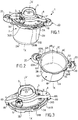
figure 1 illustre, selon une vue en perspective schématique, un appareil de cuisson d'aliments sous pression à verrouillage à baïonnette conforme à l'invention, avec le couvercle reposant librement sur la cuve en configuration de déverrouillage, l'appareil en question étant pourvu d'un organe de commande du verrouillage/déverrouillage mobile relativement au couvercle et se trouvant en l'espèce dans une position déployée correspondant au déverrouillage. - La
figure 2 illustre, selon une vue schématique en perspective plongeante, un sous-ensemble de cuve faisant partie de l'appareil de lafigure 1 , le sous-ensemble de cuve incluant une cuve métallique destinée à recevoir les aliments ainsi qu'une première et une deuxième poignée de cuve attachées à la cuve pour manipuler cette dernière. - La
figure 3 illustre un sous-ensemble de couvercle qui fait partie de l'autocuiseur de lafigure 1 , et qui est destiné à coopérer avec le sous-ensemble de cuve de lafigure 2 , ledit sous-ensemble de couvercle incluant non seulement un couvercle métallique mais également un support relativement auquel ledit couvercle peut pivoter, ainsi que l'organe de commande du verrouillage/déverrouillage qui est monté sur le support en question. - La
figure 4 illustre le sous-ensemble de couvercle de lafigure 3 représenté sous un autre angle. - La
figure 5 illustre, selon une vue de dessus, l'appareil de cuisson de lafigure 1 avec le couvercle rapporté sur la cuve et centré entre les poignées de cuves de manière à ne pas entrer en contact avec ces dernières. - Les
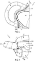
figures 6 et 7 illustrent des détails de lafigure 5 , respectivement en vue de dessus et de côté. - La
figure 8 est une vue en coupe du détail de lafigure 7 . - La
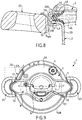
figure 9 est une vue de dessus de l'autocuiseur des figures précédentes lors du passage de la configuration de déverrouillage à la configuration de verrouillage, le couvercle métallique venant en appui latéral contre la première butée solidaire de la première poignée de cuve, la vue de lafigure 9 étant localement écorchée au niveau du couvercle pour permettre de visualiser une zone où un jeu est maintenu entre une rampe de cuve et le couvercle. - La
figure 10 est une vue agrandie d'un détail correspondant à la zone écorchée de lafigure 9 . - La
figure 11 est une vue de dessus de l'autocuiseur des figures précédentes pendant le passage de la configuration de verrouillage à la configuration de déverrouillage, le couvercle venant en appui latéral contre une deuxième butée solidaire de la première poignée de cuve. - La
figure 12 est une vue de dessous de l'autocuiseur de lafigure 11 montrant l'existence d'un jeu entre le couvercle et une rampe de cuve au voisinage d'une zone située de manière diamétralement opposée à la zone de contact entre le couvercle et la deuxième butée.
- The
figure 1 illustrates, in a schematic perspective view, a pressure cooking appliance with bayonet locking according to the invention, with the cover resting freely on the tank in unlocking configuration, the appliance in question being provided with a movable locking / unlocking control member relative to the cover and being in this case in a deployed position corresponding to the unlocking. - The
figure 2 illustrates, in a schematic view in plunging perspective, a sub-assembly of tank forming part of the apparatus of thefigure 1 , the tank sub-assembly including a metal tank intended to receive the food as well as a first and a second tank handle attached to the tank for manipulating the latter. - The
figure 3 illustrates a cover sub-assembly which is part of the pressure cooker of thefigure 1 , and which is intended to cooperate with the tank sub-assembly of thefigure 2 , said cover sub-assembly including not only a metal cover but also a support relative to which said cover can pivot, as well as the locking / unlocking control member which is mounted on the support in question. - The
figure 4 illustrates the cover sub-assembly of thefigure 3 represented from another angle. - The
figure 5 illustrates, from a top view, the cooking appliance of thefigure 1 with the cover attached to the tank and centered between the tank handles so as not to come into contact with them. - The
Figures 6 and 7 illustrate details of thefigure 5 , respectively from above and from the side. - The
figure 8 is a sectional view of the detail of thefigure 7 . - The
figure 9 is a top view of the pressure cooker of the previous figures during the transition from the unlocking configuration to the locking configuration, the metal cover coming into lateral abutment against the first stop integral with the first bowl handle, the view of thefigure 9 being locally flayed at the level of the cover to allow viewing of an area where play is maintained between a tank ramp and the cover. - The
figure 10 is an enlarged view of a detail corresponding to the cut-away area of thefigure 9 . - The
figure 11 is a top view of the pressure cooker of the previous figures during the transition from the locking configuration to the unlocking configuration, the cover coming into lateral abutment against a second stop integral with the first bowl handle. - The
figure 12 is a bottom view of the pressure cooker of thefigure 11 showing the existence of a clearance between the cover and a tank ramp in the vicinity of an area situated diametrically opposite to the contact area between the cover and the second stop.
Comme illustré aux figures, l'invention concerne un appareil de cuisson 1 d'aliments sous pression, destiné à assurer la cuisson de différents aliments à un niveau de pression supérieur à la pression atmosphérique, en présence de vapeur, et par exemple de vapeur d'eau. Ladite vapeur est générée par le chauffage, au sein de l'appareil 1 et en présence des aliments, d'un liquide de cuisson, par exemple un liquide aqueux. L'appareil 1 selon l'invention est préférentiellement destiné à un usage domestique, étant entendu toutefois que l'invention peut également concerner des appareils professionnels ou semi-professionnels. L'appareil 1 conforme à l'invention est avantageusement conçu pour monter en pression exclusivement sous l'effet d'une source de chauffe (embarquée ou externe), sans apport de pression externe. L'appareil 1 de cuisson d'aliments sous pression constitue donc un autocuiseur, destiné préférentiellement à être disposé sur une plaque de cuisson indépendante pour en chauffer le contenu. L'appareil de cuisson 1 conforme à l'invention comporte au moins une cuve métallique 2 formant récipient de cuisson, destiné à accueillir les aliments à cuire et présentant en l'espèce sensiblement une symétrie de révolution selon un axe vertical central X-X', lequel s'étend selon une direction qui s'apparente à la direction verticale lorsque l'appareil 1 est en fonctionnement normal, c'est-à-dire repose sur un plan horizontal. La cuve 2 est de manière classique réalisée, de préférence entièrement, en un matériau métallique, par exemple en acier inoxydable ou en aluminium, de préférence par emboutissage d'un flan discoïde en métal. La cuve 2 comprend un fond 2A, qui est par exemple un fond thermo-conducteur multicouches. La cuve 2 comprend également une paroi latérale annulaire 2B qui s'élève entre ledit fond 2A et un bord supérieur 2C, qui est en l'espèce de forme circulaire, et qui délimite une ouverture d'accès à l'intérieur de la cuve 2. La conformation de ce bord supérieur 2C sera décrite plus en détails dans ce qui suit, en relation avec les moyens de verrouillage de l'appareil 1.As illustrated in the figures, the invention relates to an
Avantageusement, et comme illustré aux figures, l'appareil de cuisson 1 comprend au moins une première poignée de cuve 2D fixée à ladite cuve pour permettre à un utilisateur de manipuler la cuve 2 par l'intermédiaire de ladite première poignée de cuve 2D. Cette dernière est fixée à ladite cuve 2 de façon à faire saillie extérieurement de cette dernière. Dans le mode de réalisation illustré aux figures, ladite première poignée de cuve 2D est montée sur la face externe de la paroi latérale 2B de la cuve 2, de façon à s'étendre radialement vers l'extérieur de la cuve 2 et à former ainsi une prise destinée à être attrapée manuellement par l'utilisateur pour manipuler la cuve 2 (par exemple pour la soulever et la déplacer). Dans le mode de réalisation illustré aux figures, l'appareil de cuisson 1 comprend également une deuxième poignée de cuve 2E, qui est de préférence identique à la première poignée de cuve 2D, lesdites première et deuxième poignées 2D, 2E étant avantageusement fixées sur la paroi latérale 2B de la cuve 2, de façon diamétralement opposée par rapport à l'axe central X-X', lesdites poignées de cuve 2D, 2E étant en l'espèce disposées à proximité du bord supérieur libre 2C de la cuve 2. Il est toutefois parfaitement envisageable que la cuve 2 ne soit munie que d'une seule poignée de cuve 2D, ou de plus de deux poignées de cuve (par exemple trois ou quatre), sans pour autant que l'on sorte du cadre de l'invention.Advantageously, and as illustrated in the figures, the
L'appareil 1 conforme à l'invention comprend également un couvercle métallique 3 indépendant de la cuve 2, c'est-à-dire qui n'est pas lié à la cuve 2 (notamment pas lié par une charnière), et peut être librement séparé de la cuve 2. Le couvercle 3 métallique indépendant est destiné à être rapporté sur la cuve 2, c'est-à-dire en l'espèce à venir coiffer cette dernière, pour passer d'une configuration de déverrouillage (illustrée aux
Le joint 4 est donc interposé entre la cuve 2 et le couvercle 3, de sorte que lorsque le couvercle 3 repose librement sur la cuve 2, en configuration de déverrouillage, ledit couvercle 3 repose plus précisément sur le joint 4 interposé entre la cuve 2 et le couvercle 3. Le couvercle 3 est de manière classique réalisé, de préférence entièrement, en un matériau métallique qui est de préférence le même que celui de la cuve 2, par exemple l'acier inoxydable ou l'aluminium. Le couvercle 3 présente avantageusement une forme conjuguée à celle de la cuve 2, par exemple une forme globalement discoïde, et s'étend avantageusement dans un plan moyen sensiblement parallèle au plan moyen d'extension du fond 2A de la cuve 2 (c'est-à-dire un plan sensiblement horizontal en l'espèce) lorsqu'il est rapporté et verrouillé sur cette dernière. Dans le mode de réalisation illustré aux figures, le couvercle 3 inclut un élément de couverture discoïde 3A, à partir de la périphérie duquel s'étend un bord tombant annulaire 3B. L'élément de couverture discoïde 3A est avantageusement de forme et dimensions conjuguées à celles de l'ouverture d'accès délimitée par le bord supérieur libre 2C de la paroi latérale annulaire 2B de la cuve 2, tandis que le bord tombant annulaire 3B forme une ceinture annulaire, par exemple de forme sensiblement cylindrique ou tronconique, qui s'élève entre un premier bord circulaire 30B solidaire de l'élément de couverture discoïde 3A (en l'espèce au niveau de la périphérie de ce dernier) et un second bord circulaire libre 31B. Comme illustré aux figures, l'élément de couverture discoïde 3A s'étend globalement selon un plan moyen horizontal, c'est-à-dire en l'espèce parallèle au plan moyen d'extension du fond 2A de la cuve 2 lorsque le couvercle 3 est associé à la cuve 2 pour former l'enceinte de cuisson, tandis que la ceinture annulaire 3B s'étend sensiblement verticalement, c'est-à-dire parallèlement à l'axe central X-X'. Cela n'exclut bien entendu aucunement que l'élément de couverture discoïde 3A puisse être, tel qu'illustré aux figures, légèrement bombé ou incurvé localement, par exemple pour accueillir un mécanisme de commande. Dans ce mode de réalisation, le couvercle 3 est ainsi destiné à venir coiffer de façon sensiblement ajustée le sommet de la cuve 2, de sorte que le bord tombant annulaire 3B entoure par l'extérieur le sommet de la paroi latérale annulaire 2B et le bord supérieur libre 2C, tandis que l'élément de couverture discoïde 3A repose en appui sur la cuve 2 au niveau du bord libre 2C, par l'intermédiaire du joint d'étanchéité 4 interposé entre la cuve 2 et le couvercle 3.The
La cuve 2 et le couvercle 3 constituent ainsi des enveloppes métalliques respectives complémentaires, qui une fois associées forment une enveloppe métallique résultante délimitant un volume fermé au sein duquel les aliments sont destinés à cuire sous pression de vapeur. A cette fin, l'appareil 1 de cuisson d'aliments sous pression conforme à l'invention comprend avantageusement un moyen de régulation de pression 5, comme par exemple une soupape, montée de préférence sur le couvercle 3 et agencée pour maintenir la pression régnant dans l'enceinte de cuisson à une valeur prédéterminée sensiblement constante, dite pression de fonctionnement, laquelle excède la pression atmosphérique d'une valeur qui est comprise par exemple entre sensiblement 10 et 120 kPa, de préférence de l'ordre de 100 kPa. Le principe de fonctionnement général d'un tel moyen de régulation de pression est bien connu en tant que tel, de sorte qu'il n'est pas nécessaire de le décrire plus avant ici. L'appareil 1 de cuisson d'aliments sous pression peut comporter d'autres organes de fonctionnement (par exemple un moyen de sécurité à l'ouverture, une soupape de sécurité à la surpression, etc.).The
L'appareil 1 conforme à l'invention est pourvu d'un système de verrouillage du couvercle 3 relativement à la cuve 2, afin de permettre à l'enceinte de cuisson formée par l'association de la cuve 2 et du couvercle 3 en configuration de verrouillage d'atteindre au moins la pression de fonctionnement susvisée, sans risque de voir le couvercle 3 échapper sous l'effet de la pression régnant au sein de l'enceinte. En d'autres termes, le système de verrouillage est conçu pour attacher, en configuration de verrouillage, le couvercle 3 à la cuve 2, en établissant une liaison mécanique entre la cuve 2 et le couvercle 3 qui soit suffisamment robuste pour empêcher le couvercle 3 de se séparer de la cuve 2 sous l'effet de la montée en pression au sein de l'enceinte de cuisson. De préférence, l'appareil 1 est pourvu d'un système de verrouillage à baïonnette qui inclut des rampes interverrouillables de cuve 6A - 6H et de couvercle 7A - 7H qui font respectivement partie de la cuve 2 et du couvercle 3. Ledit système de verrouillage à baïonnette est conçu, comme cela est bien connu en tant que tel, pour assurer le verrouillage et le déverrouillage du couvercle 3 relativement à la cuve 2 par pivotement du couvercle 3 relativement à la cuve 2 selon l'axe central X-X'. Ce pivotement peut faire ainsi passer l'appareil 1 d'une configuration d'attente de verrouillage (configuration de déverrouillage), dans laquelle le couvercle 3 est rapporté sur la cuve 2 et repose librement sur cette dernière, à la configuration de verrouillage précitée, dans laquelle la cuve 2 et le couvercle 3 interagissent, par l'intermédiaire de leurs rampes interverrouillables 6A - 6H, 7A - 7H respectives pour empêcher leur libre séparation, et inversement. Comme cela est bien connu en tant que tel, les rampes de cuve 6A - 6H et de couvercle 7A - 7H sont destinées à coopérer deux-à-deux, de sorte que chaque rampe 7A - 7H de couvercle est amenée, par rotation du couvercle 3 relativement à la cuve 2, à passer sous une excroissance correspondante de cuve 6A - 6H pour verrouiller le couvercle 3 relativement à la cuve 2. Dans le mode de réalisation illustré aux figures, les rampes 6A - 6H de cuve sont formées par un rebord annulaire qui déborde radialement vers l'extérieur à partir du bord supérieur 2C, des encoches étant ménagées à travers ledit rebord annulaire pour permettre le passage des rampes de couvercle 7A - 7H, de sorte que les portions dudit rebord annulaire qui s'étendent entre chaque encoche forment les rampes de cuves 6A - 6H respectives destinées à coopérer avec les rampes de couvercle 7A - 7H. Ainsi, lorsque le couvercle 3 vient coiffer la cuve 2, les rampes de couvercle 7A - 7H peuvent passer par les encoches pour se retrouver plus bas que le rebord annulaire précité. Il suffit ensuite de faire simplement tourner le couvercle 3 relativement à la cuve 2 selon l'axe central de rotation X-X' pour décaler angulairement les rampes de couvercle 7A - 7H et les encoches du rebord annulaire de la cuve 2, pour amener les rampes de couvercle 7A - 7H sous et contre les rampes de cuve 6A - 6H, réalisant de cette manière un verrouillage « à baïonnette ». Quant aux rampes de couvercles 7A - 7H, elles sont par exemple formées, comme cela est par ailleurs bien connu en tant que tel, par des languettes obtenues par repliement localisé vers l'intérieur du bord libre 31B du bord tombant annulaire 3B du couvercle 3. L'invention n'est toutefois pas limitée à la conformation spécifique des rampes de cuve 6A - 6H et de couvercle 7A - 7H décrite dans ce qui précède, et il est par exemple parfaitement envisageable de mettre en oeuvre des rampes de couvercle 7A - 7H formées par des éléments volumiques emboutis, sans pour autant que l'on sorte du cadre de l'invention. L'invention n'est pas non plus limitée à un appareil 1 mettant en oeuvre un système de verrouillage à baïonnette, et concerne tout appareil dans lequel le passage de la configuration de déverrouillage à la configuration de verrouillage ou inversement implique au moins une rotation du couvercle 3 alors qu'il repose sur la cuve 2.The
Dans une telle conception basée sur une rotation du couvercle 3 pour passer de la configuration de déverrouillage à la configuration de verrouillage ou inversement, le couvercle 3 est également susceptible de subir, à l'occasion du passage de la configuration de déverrouillage à la configuration de verrouillage ou inversement, un déplacement en translation relativement à la cuve 2 dans un plan perpendiculaire audit axe central de rotation X-X'.In such a design based on a rotation of the
En d'autres termes, le couvercle 3, lorsqu'il est déplacé relativement à la cuve 2 entre les configurations de déverrouillage et de verrouillage, peut être susceptible de se déplacer en translation dans un plan horizontal perpendiculaire à l'axe central de rotation X-X', sous l'effet de la manipulation directe ou indirecte du couvercle 3 par l'utilisateur pour le faire passer d'une configuration à l'autre. La présence de ces mouvements parasites de translation du couvercle 3 dans un plan horizontal perpendiculaire à l'axe central de rotation X-X' est accentuée par le caractère relativement instable du positionnement du couvercle 3 sur la cuve 2 lorsque le couvercle 3 repose librement sur la cuve 2, en raison de la présence du joint souple 4 interposé entre la cuve 2 et le couvercle 3.In other words, the
Dans le cas, non illustré aux figures, où le couvercle 3 est simplement doté d'une poignée de couvercle fixe, par l'intermédiaire de laquelle l'utilisateur peut imprimer au couvercle 3 un mouvement de rotation selon l'axe central X-X', les mouvements parasites de translation du couvercle 3 proviennent essentiellement de l'inévitable imperfection du mouvement imprimé manuellement par l'utilisateur au couvercle 3, mouvement qui inclut inévitablement une ou plusieurs composantes en translation.In the case, not illustrated in the figures, where the
Dans le mode de réalisation illustré aux figures, les mouvements parasites susceptibles d'être subis par le couvercle 3 entre ses configurations de déverrouillage et de verrouillage sont essentiellement impartis, de manière non souhaitée, par un mécanisme de commande manuelle du pivotement du couvercle 3 monté sur ce dernier. Plus précisément, dans le mode de réalisation avantageux illustré aux figures, l'appareil 1 comprend un support 8 auquel ledit couvercle 3 est attaché, en l'espèce de façon permanente, afin de former un sous-ensemble unitaire comprenant au moins lesdits support 8 et couvercle 3.In the embodiment illustrated in the figures, the parasitic movements likely to be undergone by the
Comme cela ressortira plus en détails de ce qui suit, le couvercle 3 est attaché au support 8 de façon à être mobile relativement à ce dernier, et en particulier de façon à pouvoir pivoter relativement au support 8 selon ledit axe central X-X', selon une course angulaire correspondant à la course angulaire requise pour faire passer l'appareil 1 de sa configuration de déverrouillage (dans laquelle le couvercle 3 repose librement sur la cuve 2 par l'intermédiaire du joint 4) à sa configuration de verrouillage, et inversement. Avantageusement, le support 8 se présente, dans le mode de réalisation illustré aux figures, sous la forme d'une traverse, c'est-à-dire d'une pièce sensiblement allongée qui s'étend diamétralement sur le couvercle 3 et qui se prolonge en l'espèce à chacune de ses extrémités par des bords tombants respectifs 8A, 8B. Dans ce mode de réalisation, l'appareil 1 comprend en outre un organe de commande 9 du verrouillage/déverrouillage qui est d'une part attaché au support 8 par une liaison mécanique autorisant le déplacement manuel dudit organe de commande 9 relativement audit support 8, et d'autre-part connecté au couvercle 3 par un dispositif de transformation dudit déplacement manuel de l'organe de commande 9 en pivotement du couvercle 3 relativement au support 8 selon ledit axe central de rotation X-X'. L'organe de commande 9 est donc avantageusement conçu pour être manipulé par l'utilisateur, de façon à permettre à ce dernier de contrôler le système de verrouillage à baïonnette afin de pouvoir faire passer, par actionnement manuel de l'organe de commande 9, l'appareil 1 de sa configuration de déverrouillage (configuration d'attente de verrouillage) à sa configuration de verrouillage, et inversement. L'organe de commande 9 est attaché au support 8, en l'espèce de façon permanente, par une liaison mécanique autorisant le déplacement manuel de l'organe de commande 9 relativement au support 8. L'organe de commande 9 est par ailleurs connecté au couvercle 3 par le dispositif de transformation précité qui est conçu pour convertir le mouvement de l'organe de commande 9 en mouvement rotatif du couvercle 3 relativement au support 8, de sorte que l'utilisateur peut ainsi commander le verrouillage et le déverrouillage par pivotement du couvercle 3 relativement au support 8 par simple manipulation de l'organe de commande 9, sans que l'utilisateur n'ait à imprimer lui-même un mouvement de rotation au couvercle 3.As will appear in more detail from the following, the
L'invention n'est pas limitée à un dispositif de transformation spécifique, et l'homme du métier pourra mettre en oeuvre tout dispositif de transformation adapté, selon la nature du mouvement de l'organe de commande 9, en utilisant les composants mécaniques habituels (du genre : roues dentées, cames, leviers, biellettes, etc.) requis. L'invention est tout particulièrement adaptée à la mise en oeuvre d'un organe de commande 9 mobile relativement au couvercle 3, car c'est dans ce cas de figure que des mouvements parasites de translation du couvercle 3, notamment dans le plan horizontal perpendiculaire à l'axe central de rotation X-X', sont particulièrement susceptibles d'être générés, sous l'effet de la manipulation indirecte du couvercle 3 par l'utilisateur, via l'organe de commande 9, pour le faire passer d'une configuration à l'autre. L'invention est donc particulièrement intéressante lorsque sont mis en oeuvre un organe de commande 9 mobile relativement au couvercle 3 (et au support 8 en l'occurrence) et un dispositif de transformation du mouvement de l'organe de commande 9 en rotation du couvercle 3 selon l'axe central X-X'. Le dispositif de transformation en question inclut de préférence au moins une pièce mobile selon un mouvement présentant au moins une composante de translation horizontale, susceptible de favoriser en retour un déplacement parasite en translation horizontale du couvercle. Une telle configuration est avantageuse car elle permet une ergonomie de commande améliorée, avec une possibilité de démultiplication du mouvement de commande manuelle exercé sur l'organe de commande 9. Les effets indésirables liés à une telle conception (éventuels mouvements parasites du couvercle 3 dans le plan horizontal) sont avantageusement contrebalancés par la conception originale décrite dans ce qui suit.The invention is not limited to a specific transformation device, and the person skilled in the art can implement any suitable transformation device, depending on the nature of the movement of the
Avantageusement, la liaison mécanique entre le support 8 et l'organe de commande 9 est conçu pour que le déplacement manuel de l'organe de commande 9 soit formé par au moins un déplacement en rotation de l'organe de commande 9 autour d'un axe de rotation Y-Y' parallèle à une direction sécante à l'axe central de rotation X-X' (comme illustré aux figures) et/ou par au moins un déplacement en translation de l'organe de commande 9 (mode de réalisation non représenté). Afin de sensiblement empêcher le support 8 de pouvoir pivoter relativement à la cuve 2 selon l'axe central de rotation X-X' lors dudit déplacement manuel de l'organe de commande 9, les support 8 et cuve 2 sont avantageusement conçus, comme illustré aux figures, pour interagir, lorsque le couvercle 3 est rapporté sur la cuve 2 pour former l'enceinte de cuisson. En d'autres termes, l'association du couvercle 3 et de la cuve 2 dans la configuration de déverrouillage illustrée par exemple à la
Chaque conformation de cuve 20, 21 forme ainsi préférentiellement un élément femelle tandis que chaque conformation de support 80, 81 forme un élément mâle complémentaire dudit élément femelle. Lorsque l'utilisateur rapporte le sous-ensemble de couvercle (formé par le couvercle 3, le support 8 et l'organe de commande 9) sur le sous-ensemble de cuves (formé par la cuve 2 et ses poignées 2D, 2E conformées pour constituer les première et deuxième conformations de cuve 20, 21), les bords tombants 8A, 8B du support 8 viennent se loger dans les logements complémentaires correspondant aux première et deuxième conformations de cuves 20, 21, le couvercle 3 reposant librement sur la cuve 2 par l'intermédiaire du joint d'étanchéité 4. Dans cette configuration de déverrouillage, illustré par la
Ce dernier se présente avantageusement sous la forme d'un élément rotatif du type poignée, levier, manette ou anse et/ou d'un élément coulissant tel qu'un bouton-poussoir, un curseur ou autre. Dans le mode de réalisation préférentiel illustré aux figures, l'organe de commande 9 se présente sous la forme d'une anse pivotante montée à rotation selon un axe radial Y-Y' perpendiculaire à l'axe vertical central X-X'. L'anse en question peut ainsi évoluer par rotation selon l'axe de rotation Y-Y' entre une position déployée (
Le dispositif de transformation qui transforme le déplacement manuel de l'organe de commande 9 en pivotement du couvercle 3 relativement au support 8 selon ledit axe central de rotation X-X' est par exemple conforme à l'enseignement de l'un et/ou l'autre des demandes de brevets européens publiées sous les numéros suivants :
La coopération entre les conformations de support 80, 81 et de cuve 20, 21 est susceptible de limiter ces déplacements en translation parasite dans un plan perpendiculaire à l'axe central de rotation X-X', mais avec toutefois une efficacité très difficile à contrôler en raison notamment des multiples jeux à prendre en considération, compte-tenu de la multiplicité de pièces concernées dans la chaîne de cotes (cuve 2, poignées 2D, 2E, couvercle 3, support 8, organe de commande 9, joint 4, dispositif de transformation de mouvement incluant lui-même une multiplicité de pièces en mouvement...). Le déplacement intempestif du couvercle 3 en translation perpendiculairement à l'axe central de rotation X-X' dépend donc de toute la reprise de jeux de tous les composants mécaniques concernés, ce qui rend la maîtrise et la limitation de ce mouvement parasite en translation horizontale très difficiles, sinon impossibles en pratique.The cooperation between the
Il résulte ainsi un risque de mise en contact localisé du couvercle 3 et de la cuve 2, et plus précisément de la face interne 300B du bord tombant 3B et du bord latéral libre des rampes de cuves 6A - 6H. Ce contact, même localisé, entraîne des frottements métal/métal qui nuisent au bon fonctionnement de l'organe de commande 9 et à l'ergonomie d'utilisation. L'utilisateur est en effet contraint, pour surmonter les forces de réaction résultant de ces frottements intempestifs métal/métal, d'exercer un effort supplémentaire pour verrouiller ou déverrouiller le couvercle 3 relativement à la cuve 2.This results in a risk of localized contacting of the
Afin de surmonter ce problème et limiter le risque de survenance de frottements métal/métal entre la cuve 3 et le couvercle 2, l'invention propose de limiter le déplacement du couvercle 3 par rapport au centre de l'appareil (matérialisé par l'axe vertical central X-X') dans le plan perpendiculaire à l'axe central de rotation X-X' lors de la manipulation de l'appareil 1 pour le faire passer de cette configuration de déverrouillage à sa configuration de verrouillage ou inversement. Pour cela, l'appareil 1 comprend au moins une première butée 10 non métallique fixée à la cuve 2 et disposée relativement au couvercle 3 pour limiter la course dudit déplacement en translation du couvercle 3 selon une première direction D1, par mise en appui du couvercle 3 contre ladite première butée 10. La première butée 10 est donc fixée à la cuve 2, c'est-à-dire qu'elle est attachée de manière permanente directement à la cuve 2, dans une position fixe par rapport à cette dernière. La position de la première butée 10 relativement à la cuve 2 est choisie pour que le couvercle, lorsqu'il se déplace en translation selon la première direction D1 dans un plan perpendiculaire à l'axe central de rotation X-X', vienne en contact direct contre ladite première butée10 et soit ainsi empêché, par cette mise en butée, de poursuivre sa course en translation selon la première direction D1. Cette mise en appui du couvercle 3 contre la première butée 10 empêche ainsi le couvercle 3 de poursuivre sa translation et de venir localement directement en appui contre la cuve 2 selon un contact métal/métal. Plus précisément, la première butée 10 permet, lorsque le couvercle 3 se déplace en translation selon la première direction D1, d'empêcher le couvercle 3 de venir au contact direct de la cuve 2 dans un secteur angulaire de la cuve 2 qui est sensiblement diamétralement opposée au secteur angulaire où est positionné la première butée 10. De cette façon, lorsque le couvercle 3 subit, à l'occasion du passage de la configuration de déverrouillage à la configuration de verrouillage ou inversement, un déplacement en translation selon la première direction D1 dans le plan perpendiculaire à l'axe central de rotation X-X', le couvercle 2 viendra d'abord en contact avec la première butée 10, avant pouvoir de venir en contact avec la cuve 2 (ce que lui interdit en réalité la première butée 10).In order to overcome this problem and limit the risk of metal / metal friction occurring between the
Cela signifie que l'appareil 1 selon l'invention est capable de mettre en oeuvre la séquence suivante :
- ▪ le couvercle 3 repose librement sur la cuve 2, de manière centrée de sorte qu'il ne se trouve sensiblement pas en contact avec la cuve 2 sur l'ensemble de son périmètre (
figure 5 ) et qu'il n'est pas non plus en contact avec la première butée 10 (existence d'un jeu J0 non nul entre la première butée 10 et laface externe 301A du bord tombant annulaire 3B du couvercle 3); - ▪ l'utilisateur entraîne le couvercle 3 en rotation pour passer de la configuration de déverrouillage à la configuration de verrouillage, ce qui entraîne simultanément un déplacement parasite en translation du couvercle 3 relativement à la cuve 2 selon la première direction D1, dans un plan perpendiculaire à l'axe central de rotation X-X' (
figure 9 ); - ▪ le couvercle 3 progresse alors en translation selon la direction D1 jusqu'à venir en butée contre la première butée 10, qui empêche le couvercle 3 de venir en contact, dans la zone diamétralement opposée Z0, avec la cuve 2 (existence d'un jeu J1 non nul entre la cuve 2 et
la face interne 300B du bord tombant annulaire 3B du couvercle 3) ; le couvercle tourne concomitamment selon l'axe central de rotation X-X', tout en frottant contre ladite première butée 10 ; ce frottement est cependant beaucoup moins incommodant pour l'utilisateur que le frottement métal/métal rencontré dans l'art antérieur, car il génère une résistance à la rotation beaucoup plus faible en raison de la mise en contact de métal d'une part (le couvercle 3) et d'un matériau non métallique d'autre part (la première butée 10) ;
l'invention permet donc d'éviter un contact métal/métal qui nuit à l'ergonomie et au bon fonctionnement de l'appareil 1.
- ▪ the
cover 3 rests freely on thetank 2, in a centered manner so that it is not substantially in contact with thetank 2 over its entire perimeter (figure 5 ) and that it is also not in contact with the first stop 10 (existence of a non-zero clearance J0 between thefirst stop 10 and theexternal face 301A of the annular fallingedge 3B of the cover 3); - ▪ the user drives the
cover 3 in rotation to pass from the unlocking configuration to the locking configuration, which simultaneously causes a parasitic displacement in translation of thecover 3 relative to thetank 2 in the first direction D1, in a perpendicular plane to the central axis of rotation XX '(figure 9 ); - ▪ the
cover 3 then progresses in translation in the direction D1 until it comes into abutment against thefirst stop 10, which prevents thecover 3 from coming into contact, in the diametrically opposite zone Z0, with the tank 2 (existence of a non-zero clearance J1 between thetank 2 and theinternal face 300B of the annular fallingedge 3B of the cover 3); the cover rotates concomitantly along the central axis of rotation XX ′, while rubbing against saidfirst stop 10; this friction is however much less inconvenient for the user than the metal / metal friction encountered in the prior art, because it generates a much lower resistance to rotation due to the contacting of metal on the one hand (the cover 3) and a non-metallic material on the other hand (the first stop 10);
the invention therefore makes it possible to avoid metal / metal contact which adversely affects the ergonomics and the proper functioning of thedevice 1.
Avantageusement, la première butée 10 est réalisée en matière plastique, ce qui permet un contact plastique/métal particulièrement avantageux sur le plan tribologique. Dans ce mode de réalisation préférentiel, illustré aux figures, le couvercle 3 en rotation frotte donc directement contre la première butée 10 en plastique, le contact métal/plastique minimisant les forces de réactions s'opposant au déplacement en rotation du couvercle 3 relativement à la cuve 2 selon l'axe central de rotation X-X'. L'invention n'est toutefois pas limitée à la mise en oeuvre d'une première butée 10 en matière plastique, et d'autres matériaux synthétiques ou naturels peuvent parfaitement être envisagés sans pour autant que l'on sorte du cadre de l'invention. De façon préférentielle, la première butée 10 est réalisée en un matériau thermodurcissable, comme par exemple une résine phénol-formaldéhyde, telle que la Bakélite®, qui s'avère particulièrement avantageux sur le plan tribologique, notamment lorsque le couvercle 3 est réalisé en aluminium ou en acier inoxydable. Il est cependant tout à fait envisageable d'employer d'autres matériaux plastiques, comme par exemple un matériau thermoplastique, sans pour autant que l'on sorte du cadre de l'invention.Advantageously, the
De préférence, la première butée 10, et plus précisément la surface de butée de cette dernière contre laquelle est destiné à venir en appui le couvercle 3, s'inscrit dans un cercle de diamètre d0 qui est lié au diamètre hors tout d1 du couvercle 3 (correspondant au diamètre du bord tombant cylindrique 3B) par la formule suivante : ![]()
![]()
L'invention a permis de mettre en évidence qu'un jeu J0 compris entre 0,2 mm et 1 mm, de préférence compris entre sensiblement 0,5 mm et 0,9 mm, par exemple égal à environ 0,8 mm, lorsque le couvercle se trouve dans la position centrée de la
De préférence, ladite première butée 10 non métallique présente une forme angulaire, c'est-à-dire une forme en « coin », saillante, pour favoriser un contact ponctuel entre lesdits première butée 10 non métallique et couvercle 3 métallique, ce qui limite les effets de freinage dus aux frottements.Preferably, said first
Dans le mode de réalisation illustré aux figures, la première butée 10 est positionnée en regard dudit bord tombant annulaire 3B du couvercle 3, lorsque ce dernier est rapporté sur la cuve 2, pour que ladite limitation de la course soit obtenue par mise en appui dudit bord tombant annulaire 3B (métallique) contre la première butée 10 (non métallique). Le couvercle 3 est donc conçu, lorsqu'il subit le déplacement intempestif en translation dans le plan horizontal perpendiculaire à l'axe central de rotation X-X', pour que la face externe 301 B de son bord tombant 3B vienne localement en appui contre la première butée 10. Ainsi, en configuration de déverrouillage, le bord tombant annulaire 3B du couvercle 3 est interposé localement entre d'une part la première butée 10, et d'autre part le bord le plus extérieur de la cuve 2, correspondant par exemple au bord libre 60E de l'une des languettes formant rampe de cuve 6E. Ainsi, lorsque l'utilisateur sollicite manuellement l'organe de commande 9, pour faire passer le couvercle 3 de l'une de ses configurations de déverrouillage ou verrouillage à l'autre, il va simultanément contraindre le couvercle 3 en translation selon la première direction D1, rapprochant ainsi localement, dans la zone Z0, la face interne 300B du bord tombant 3B et le bord libre 60A de la rampe de cuve 6A présente dans cette zone Z0. Toutefois, la face externe 301 B du bord tombant 3B va venir en contact et en appui contre la première butée 10 avant que la face interne du bord tombant 3B ne puisse venir au contact du bord extérieur libre 60A de la rampe de cuve 6A, un jeu J1, par exemple compris entre 0,2 et 1 mm, de préférence entre 0,5 et 0,9 mm, étant ainsi maintenu localement entre la cuve 2 (et plus précisément la rampe de cuve 6A) et le couvercle 3 (et plus précisément la face interne 300B du bord tombant 3B). Un jeu radial, correspondant localement au jeu J1 précité, est ainsi ménagé entre le couvercle 3 et la cuve 2 lorsque le couvercle 3 repose sur la cuve 2 et est en appui contre la première butée 10.In the embodiment illustrated in the figures, the
Avantageusement, ladite première butée 10 non métallique est portée par ladite première poignée de cuve 2D, et de façon encore plus avantageuse ladite première butée 10 non métallique vient de matière avec ladite première poignée de cuve 2D. En d'autres termes, dans le mode de réalisation préférentiel illustré aux figures, l'appareil 1 comprend une seule et même pièce, qui joue à la fois le rôle de première poignée de cuve 2D et de première butée 10. Par exemple, la première poignée 2D présente une forme sensiblement annulaire avec une excroissance localisée formant ladite première butée 10 non métallique. De préférence, la première poignée 2D présente plus précisément une première portion arrondie formant moyen de préhension et destinée à être saisie à la main par l'utilisateur, cette première portion arrondie s'étendant entre deux extrémités reliées entre elles par une portion de garde, laquelle est incurvée pour délimiter le logement correspondant à la première conformation de cuve 20 évoquée précédemment. L'une des extrémités en question est dotée d'une excroissance en coin formant avantageusement la première butée 10. Bien évidemment, l'invention n'est absolument pas limitée à ce mode de réalisation particulière, et il est tout à fait envisageable que la première butée 10 soit formée non pas par une excroissance localisée, mais par un patin surfacique, qui donnerait toutefois de moins bons résultats car il ne favoriserait pas un contact ponctuel susceptible de limiter les frottements. Il est également parfaitement envisageable que la première butée 10 ne soit pas portée ou venue de matière avec la première poignée 2D, mais soit plutôt constituée par une pièce indépendante de la première poignée 2D, fixée de manière séparée sur la cuve 2 par tout moyen approprié (par exemple via un pontet soudé).Advantageously, said first
Dans le mode de réalisation préférentiel illustré aux figures, l'appareil 1 comprend avantageusement au moins une deuxième butée 11, de préférence elle aussi non métallique, fixée à la cuve 2 et disposée relativement au couvercle 3 pour limiter la course dudit déplacement translation du couvercle 3 selon une deuxième direction D2 sécante avec ladite première direction D1, par mise en appui du couvercle 3 contre ladite deuxième butée 11. La deuxième butée 11 est donc conçue pour avantageusement jouer le même rôle que la première butée 10, à la seule différence près que ce rôle s'exerce pour limiter le déplacement en translation du couvercle 3 selon la deuxième direction D2. La description qui précède concernant la première butée 10 est donc valable, mutatis mutandis, pour la deuxième butée 11. La mise en oeuvre de deux butées 10, 11 est particulièrement préféré car elle permet de tenir compte du fait que le déplacement intempestif en translation du couvercle 3 n'est pas forcément le même dans le sens du verrouillage que dans le sens du déverrouillage. Par exemple, dans le mode de réalisation illustré aux figures, les premières et deuxième directions D1, D2 forment entre elles un angle saillant compris entre 10 et 45 degrés, de préférence compris entre 20 et 30 degrés.In the preferred embodiment illustrated in the figures, the
Avantageusement, la deuxième butée 11 non métallique est en matière plastique, et est également portée par la première poignée de cuve 2D, et vient de façon encore plus préférentielle également de matière avec ladite première poignée de cuve 2D, tout comme la première butée 10. Dans ce mode de réalisation particulièrement avantageux, la première poignée de cuve 2D présente avantageusement une forme sensiblement symétrique, chaque extrémité de la portion de garde qui relie les extrémités de la portion courbe de préhension manuelle étant pourvue d'une excroissance localisée, en forme de coin, constituant respectivement la première butée 10 et la deuxième butée 11. De préférence, la deuxième butée 11, et plus précisément la surface de butée de cette dernière contre laquelle est destiné à venir en appui le couvercle 3, s'inscrit dans le cercle de diamètre d0 évoqué précédemment.Advantageously, the second
De manière particulièrement avantageuse, la deuxième poignée 2E est identique à la première poignée 2D, et est disposée sur la cuve 2de manière diamétralement opposée, en miroir, relativement à la première poignée 2D. Afin d'autoriser un positionnement du sous-ensemble de couvercle dans un sens ou dans l'autre, la deuxième poignée de cuve 2E porte elle aussi des excroissances localisées en forme de coin 12, 13 susceptibles de jouer le rôle des première et deuxième butées 10, 11 lorsque le couvercle 3 repose sur la cuve 2 dans une position décalée de 180° par rapport à la position illustrée aux
Le fonctionnement de l'appareil de cuisson 1 illustré aux figures va maintenant être décrit brièvement. L'utilisateur remplit tout d'abord la cuve 2 illustrée à la
Le couvercle 3 tourne autour de l'axe central de rotation X-X' en direction de la configuration de verrouillage.Le couvercle 3 se déplace légèrement, de manière parasite, en translation selon la première direction D1, dans un plan perpendiculaire à l'axe central de rotation X-X', jusqu'à venir en butée contre la première butée 10, comme illustré à lafigure 9 . Le jeu J0 devient donc nul. Cette mise en butée permet d'empêcher laface interne 300B du bord tombant annulaire 3B du couvercle 3 de venir frotter latéralement contre le bordlibre 60A de la rampe de cuve 6A, un jeu non nul J1, de l'ordrepar exemple d'environ 0,8 mm, étant maintenu dans la zone Z0 diamétralement opposée à la zone oùla face externe 301 B du bord tombant annulaire 3B vient en appui contre la première butée 10.
- The
cover 3 rotates around the central axis of rotation XX 'in the direction of the locking configuration. - The
cover 3 moves slightly, parasitically, in translation in the first direction D1, in a plane perpendicular to the central axis of rotation X-X ', until it abuts against thefirst stop 10, as illustrated in thefigure 9 . The game J0 therefore becomes zero. This abutment makes it possible to prevent theinternal face 300B of the fallingannular edge 3B of thecover 3 from coming to rub laterally against thefree edge 60A of thetank ramp 6A, a non-zero clearance J1, of the order for example of approximately 0.8 mm, being held in the zone Z0 diametrically opposite to the zone where theexternal face 301 B of the fallingannular edge 3B comes to bear against thefirst stop 10.
L'appareil 1 se trouve alors en configuration de verrouillage et peut monter en pression et en température pour cuire les aliments.The
À la fin du cycle de cuisson, l'utilisateur exerce sur l'organe de commande 9 une traction manuelle visant à relever l'organe de commande manuelle 9 pour déverrouiller le couvercle 3 relativement à la cuve 2. Cette opération entraîne les deux phénomènes sensiblement concomitants suivants :
Le couvercle 3 tourne autour de l'axe central de rotation X-X' en direction de la configuration de déverrouillage.Le couvercle 3 se déplace légèrement, de manière parasite, en translation selon la deuxième direction D2, dans un plan perpendiculaire à l'axe central de rotation X-X', jusqu'à venir en butée contre la deuxième butée 11, comme illustré à lafigure 11 . Le jeu J2 devient donc nul. Cette mise en butée permet d'empêcher laface interne 300B du bord tombant annulaire 3B du couvercle 3 de venir frotter latéralement contre le bordlibre 60H de la rampe de cuve 6H, un jeu non nul J13, de l'ordrepar exemple de 0,8 mm, étant maintenu dans la zone diamétralement opposée à la zone oùla face externe 301 B du bord tombant annulaire 3B vient en appui contre la deuxième butée 11.
- The
cover 3 rotates around the central axis of rotation XX 'in the direction of the unlocking configuration. - The
cover 3 moves slightly, parasitically, in translation in the second direction D2, in a plane perpendicular to the central axis of rotation X-X ', until it comes into abutment against thesecond abutment 11, as illustrated in thefigure 11 . The J2 clearance therefore becomes zero. This abutment prevents theinternal face 300B of the fallingannular edge 3B of thecover 3 from rubbing laterally against thefree edge 60H of thetank ramp 6H, a non-zero clearance J13, of the order for example of 0 , 8 mm, being held in the zone diametrically opposite to the zone where theexternal face 301 B of the fallingannular edge 3B abuts against thesecond stop 11.
L'invention permet ainsi de limiter drastiquement les contacts métal/métal au verrouillage comme au déverrouillage, ce qui contribue à améliorer considérablement l'ergonomie de fonctionnement et la fiabilité de l'appareil 1.The invention thus makes it possible to drastically limit the metal / metal contacts during locking as well as when unlocking, which contributes to considerably improving the ergonomics of operation and the reliability of the
Claims (15)
Applications Claiming Priority (1)
| Application Number | Priority Date | Filing Date | Title |
|---|---|---|---|
| FR1855709A FR3082717B1 (en) | 2018-06-26 | 2018-06-26 | PRESSURE COOKER WITH LID STOPPER |
Publications (2)
| Publication Number | Publication Date |
|---|---|
| EP3586689A1 true EP3586689A1 (en) | 2020-01-01 |
| EP3586689B1 EP3586689B1 (en) | 2022-05-04 |
Family
ID=63491721
Family Applications (1)
| Application Number | Title | Priority Date | Filing Date |
|---|---|---|---|
| EP19182211.3A Active EP3586689B1 (en) | 2018-06-26 | 2019-06-25 | Pressure cooker provided with an abutment for a lid |
Country Status (5)
| Country | Link |
|---|---|
| EP (1) | EP3586689B1 (en) |
| CN (1) | CN110638322B (en) |
| BR (1) | BR102019013220A2 (en) |
| CO (1) | CO2019006647A1 (en) |
| FR (1) | FR3082717B1 (en) |
Families Citing this family (3)
| Publication number | Priority date | Publication date | Assignee | Title |
|---|---|---|---|---|
| CN110250930A (en) | 2017-08-09 | 2019-09-20 | 沙克忍者运营有限责任公司 | Cooking system |
| CN212788226U (en) | 2019-02-25 | 2021-03-26 | 沙克忍者运营有限责任公司 | Cooking system |
| US11647861B2 (en) | 2020-03-30 | 2023-05-16 | Sharkninja Operating Llc | Cooking device and components thereof |
Citations (6)
| Publication number | Priority date | Publication date | Assignee | Title |
|---|---|---|---|---|
| GB657982A (en) * | 1949-04-29 | 1951-10-03 | Midland Metal Spinning Company | Pressure cookers |
| EP3100653A1 (en) | 2015-06-02 | 2016-12-07 | Seb S.A. | Bayonet pressure cooker provided with a controller |
| EP3100654A1 (en) | 2015-06-02 | 2016-12-07 | Seb S.A. | Bayonet pressure cooker provided with a vessel handle |
| EP3100652A1 (en) | 2015-06-02 | 2016-12-07 | Seb S.A. | Pressure cooker provided with a member for manual locking control |
| EP3100655A1 (en) | 2015-06-02 | 2016-12-07 | Seb S.A. | Bayonet pressure cooker provided with guide elements |
| EP3329810A1 (en) * | 2016-12-02 | 2018-06-06 | Seb S.A. | Pressure cooker with bayonet and mobile lock |
Family Cites Families (2)
| Publication number | Priority date | Publication date | Assignee | Title |
|---|---|---|---|---|
| CN204181448U (en) * | 2014-08-29 | 2015-03-04 | 松下家电研究开发(杭州)有限公司 | A kind of cooking apparatus of safe opening |
| FR3046043B1 (en) * | 2015-12-23 | 2018-01-26 | Seb S.A. | REINFORCING COOKER |
-
2018
- 2018-06-26 FR FR1855709A patent/FR3082717B1/en active Active
-
2019
- 2019-06-21 CO CONC2019/0006647A patent/CO2019006647A1/en unknown
- 2019-06-25 EP EP19182211.3A patent/EP3586689B1/en active Active
- 2019-06-25 BR BR102019013220A patent/BR102019013220A2/en active Search and Examination
- 2019-06-26 CN CN201910559796.7A patent/CN110638322B/en active Active
Patent Citations (6)
| Publication number | Priority date | Publication date | Assignee | Title |
|---|---|---|---|---|
| GB657982A (en) * | 1949-04-29 | 1951-10-03 | Midland Metal Spinning Company | Pressure cookers |
| EP3100653A1 (en) | 2015-06-02 | 2016-12-07 | Seb S.A. | Bayonet pressure cooker provided with a controller |
| EP3100654A1 (en) | 2015-06-02 | 2016-12-07 | Seb S.A. | Bayonet pressure cooker provided with a vessel handle |
| EP3100652A1 (en) | 2015-06-02 | 2016-12-07 | Seb S.A. | Pressure cooker provided with a member for manual locking control |
| EP3100655A1 (en) | 2015-06-02 | 2016-12-07 | Seb S.A. | Bayonet pressure cooker provided with guide elements |
| EP3329810A1 (en) * | 2016-12-02 | 2018-06-06 | Seb S.A. | Pressure cooker with bayonet and mobile lock |
Also Published As
| Publication number | Publication date |
|---|---|
| CN110638322A (en) | 2020-01-03 |
| CN110638322B (en) | 2021-08-10 |
| CO2019006647A1 (en) | 2019-07-31 |
| FR3082717A1 (en) | 2019-12-27 |
| FR3082717B1 (en) | 2020-07-03 |
| BR102019013220A2 (en) | 2020-01-14 |
| EP3586689B1 (en) | 2022-05-04 |
Similar Documents
| Publication | Publication Date | Title |
|---|---|---|
| EP3100652B1 (en) | Pressure cooker provided with a member for manual locking control | |
| EP3100653B1 (en) | Bayonet pressure cooker provided with a controller | |
| FR3036936B1 (en) | BAIONNETTE COOKER WITH A TANK HANDLE | |
| FR3059534B1 (en) | BAIONNETTE COOKER AND MOBILE LOCK | |
| EP3238580B1 (en) | Pressure cooker provided with a lid opening | |
| EP1344476B1 (en) | Apparatus for cooking food under pressure with a rotative locking device | |
| EP3100655B1 (en) | Bayonet pressure cooker provided with guide elements | |
| EP3457897B1 (en) | Pressure cooking appliance with improved control ergonomics | |
| EP1938717B1 (en) | Pressure-cooking device provided with a bolt | |
| EP2687132B1 (en) | Appliance for cooking food under pressure with improved control device | |
| EP2624728B1 (en) | Pressure cooking appliance including a disengageable control member | |
| EP2732736B1 (en) | Appliance for cooking food under pressure comprising an improved control device | |
| EP3586689B1 (en) | Pressure cooker provided with an abutment for a lid | |
| EP3329809B1 (en) | Bayonet pressure cooker with interlocking pot and lid handles | |
| WO2005053483A1 (en) | Pressurized cooking device with a single control element for decompression and locking/unlocking | |
| EP1547497B1 (en) | Domestic pressure cooking appliance with improved locking device | |
| EP1720433B1 (en) | Domestic pressure food cooking device with improved guide for the locking means | |
| FR2994814A1 (en) | SIMPLIFIEDLY MANUFACTURED PRESSURE COOKER COVER AND PRESSURIZED COOKING APPARATUS EQUIPPED WITH SUCH COVER |
Legal Events
| Date | Code | Title | Description |
|---|---|---|---|
| PUAI | Public reference made under article 153(3) epc to a published international application that has entered the european phase |
Free format text: ORIGINAL CODE: 0009012 |
|
| STAA | Information on the status of an ep patent application or granted ep patent |
Free format text: STATUS: THE APPLICATION HAS BEEN PUBLISHED |
|
| AK | Designated contracting states |
Kind code of ref document: A1 Designated state(s): AL AT BE BG CH CY CZ DE DK EE ES FI FR GB GR HR HU IE IS IT LI LT LU LV MC MK MT NL NO PL PT RO RS SE SI SK SM TR |
|
| AX | Request for extension of the european patent |
Extension state: BA ME |
|
| STAA | Information on the status of an ep patent application or granted ep patent |
Free format text: STATUS: REQUEST FOR EXAMINATION WAS MADE |
|
| 17P | Request for examination filed |
Effective date: 20200331 |
|
| RBV | Designated contracting states (corrected) |
Designated state(s): AL AT BE BG CH CY CZ DE DK EE ES FI FR GB GR HR HU IE IS IT LI LT LU LV MC MK MT NL NO PL PT RO RS SE SI SK SM TR |
|
| GRAP | Despatch of communication of intention to grant a patent |
Free format text: ORIGINAL CODE: EPIDOSNIGR1 |
|
| STAA | Information on the status of an ep patent application or granted ep patent |
Free format text: STATUS: GRANT OF PATENT IS INTENDED |
|
| RIC1 | Information provided on ipc code assigned before grant |
Ipc: A47J 27/08 20060101AFI20211008BHEP |
|
| INTG | Intention to grant announced |
Effective date: 20211116 |
|
| GRAS | Grant fee paid |
Free format text: ORIGINAL CODE: EPIDOSNIGR3 |
|
| GRAA | (expected) grant |
Free format text: ORIGINAL CODE: 0009210 |
|
| STAA | Information on the status of an ep patent application or granted ep patent |
Free format text: STATUS: THE PATENT HAS BEEN GRANTED |
|
| AK | Designated contracting states |
Kind code of ref document: B1 Designated state(s): AL AT BE BG CH CY CZ DE DK EE ES FI FR GB GR HR HU IE IS IT LI LT LU LV MC MK MT NL NO PL PT RO RS SE SI SK SM TR |
|
| REG | Reference to a national code |
Ref country code: GB Ref legal event code: FG4D Free format text: NOT ENGLISH |
|
| REG | Reference to a national code |
Ref country code: CH Ref legal event code: EP |
|
| REG | Reference to a national code |
Ref country code: AT Ref legal event code: REF Ref document number: 1488114 Country of ref document: AT Kind code of ref document: T Effective date: 20220515 |
|
| REG | Reference to a national code |
Ref country code: DE Ref legal event code: R096 Ref document number: 602019014357 Country of ref document: DE |
|
| REG | Reference to a national code |
Ref country code: IE Ref legal event code: FG4D Free format text: LANGUAGE OF EP DOCUMENT: FRENCH |
|
| REG | Reference to a national code |
Ref country code: LT Ref legal event code: MG9D |
|
| REG | Reference to a national code |
Ref country code: NL Ref legal event code: MP Effective date: 20220504 |
|
| REG | Reference to a national code |
Ref country code: AT Ref legal event code: MK05 Ref document number: 1488114 Country of ref document: AT Kind code of ref document: T Effective date: 20220504 |
|
| PG25 | Lapsed in a contracting state [announced via postgrant information from national office to epo] |
Ref country code: SE Free format text: LAPSE BECAUSE OF FAILURE TO SUBMIT A TRANSLATION OF THE DESCRIPTION OR TO PAY THE FEE WITHIN THE PRESCRIBED TIME-LIMIT Effective date: 20220504 Ref country code: PT Free format text: LAPSE BECAUSE OF FAILURE TO SUBMIT A TRANSLATION OF THE DESCRIPTION OR TO PAY THE FEE WITHIN THE PRESCRIBED TIME-LIMIT Effective date: 20220905 Ref country code: NO Free format text: LAPSE BECAUSE OF FAILURE TO SUBMIT A TRANSLATION OF THE DESCRIPTION OR TO PAY THE FEE WITHIN THE PRESCRIBED TIME-LIMIT Effective date: 20220804 Ref country code: NL Free format text: LAPSE BECAUSE OF FAILURE TO SUBMIT A TRANSLATION OF THE DESCRIPTION OR TO PAY THE FEE WITHIN THE PRESCRIBED TIME-LIMIT Effective date: 20220504 Ref country code: LT Free format text: LAPSE BECAUSE OF FAILURE TO SUBMIT A TRANSLATION OF THE DESCRIPTION OR TO PAY THE FEE WITHIN THE PRESCRIBED TIME-LIMIT Effective date: 20220504 Ref country code: HR Free format text: LAPSE BECAUSE OF FAILURE TO SUBMIT A TRANSLATION OF THE DESCRIPTION OR TO PAY THE FEE WITHIN THE PRESCRIBED TIME-LIMIT Effective date: 20220504 Ref country code: GR Free format text: LAPSE BECAUSE OF FAILURE TO SUBMIT A TRANSLATION OF THE DESCRIPTION OR TO PAY THE FEE WITHIN THE PRESCRIBED TIME-LIMIT Effective date: 20220805 Ref country code: FI Free format text: LAPSE BECAUSE OF FAILURE TO SUBMIT A TRANSLATION OF THE DESCRIPTION OR TO PAY THE FEE WITHIN THE PRESCRIBED TIME-LIMIT Effective date: 20220504 Ref country code: ES Free format text: LAPSE BECAUSE OF FAILURE TO SUBMIT A TRANSLATION OF THE DESCRIPTION OR TO PAY THE FEE WITHIN THE PRESCRIBED TIME-LIMIT Effective date: 20220504 Ref country code: BG Free format text: LAPSE BECAUSE OF FAILURE TO SUBMIT A TRANSLATION OF THE DESCRIPTION OR TO PAY THE FEE WITHIN THE PRESCRIBED TIME-LIMIT Effective date: 20220804 Ref country code: AT Free format text: LAPSE BECAUSE OF FAILURE TO SUBMIT A TRANSLATION OF THE DESCRIPTION OR TO PAY THE FEE WITHIN THE PRESCRIBED TIME-LIMIT Effective date: 20220504 |
|
| PG25 | Lapsed in a contracting state [announced via postgrant information from national office to epo] |
Ref country code: RS Free format text: LAPSE BECAUSE OF FAILURE TO SUBMIT A TRANSLATION OF THE DESCRIPTION OR TO PAY THE FEE WITHIN THE PRESCRIBED TIME-LIMIT Effective date: 20220504 Ref country code: PL Free format text: LAPSE BECAUSE OF FAILURE TO SUBMIT A TRANSLATION OF THE DESCRIPTION OR TO PAY THE FEE WITHIN THE PRESCRIBED TIME-LIMIT Effective date: 20220504 Ref country code: LV Free format text: LAPSE BECAUSE OF FAILURE TO SUBMIT A TRANSLATION OF THE DESCRIPTION OR TO PAY THE FEE WITHIN THE PRESCRIBED TIME-LIMIT Effective date: 20220504 Ref country code: IS Free format text: LAPSE BECAUSE OF FAILURE TO SUBMIT A TRANSLATION OF THE DESCRIPTION OR TO PAY THE FEE WITHIN THE PRESCRIBED TIME-LIMIT Effective date: 20220904 |
|
| PG25 | Lapsed in a contracting state [announced via postgrant information from national office to epo] |
Ref country code: SM Free format text: LAPSE BECAUSE OF FAILURE TO SUBMIT A TRANSLATION OF THE DESCRIPTION OR TO PAY THE FEE WITHIN THE PRESCRIBED TIME-LIMIT Effective date: 20220504 Ref country code: SK Free format text: LAPSE BECAUSE OF FAILURE TO SUBMIT A TRANSLATION OF THE DESCRIPTION OR TO PAY THE FEE WITHIN THE PRESCRIBED TIME-LIMIT Effective date: 20220504 Ref country code: RO Free format text: LAPSE BECAUSE OF FAILURE TO SUBMIT A TRANSLATION OF THE DESCRIPTION OR TO PAY THE FEE WITHIN THE PRESCRIBED TIME-LIMIT Effective date: 20220504 Ref country code: EE Free format text: LAPSE BECAUSE OF FAILURE TO SUBMIT A TRANSLATION OF THE DESCRIPTION OR TO PAY THE FEE WITHIN THE PRESCRIBED TIME-LIMIT Effective date: 20220504 Ref country code: DK Free format text: LAPSE BECAUSE OF FAILURE TO SUBMIT A TRANSLATION OF THE DESCRIPTION OR TO PAY THE FEE WITHIN THE PRESCRIBED TIME-LIMIT Effective date: 20220504 Ref country code: CZ Free format text: LAPSE BECAUSE OF FAILURE TO SUBMIT A TRANSLATION OF THE DESCRIPTION OR TO PAY THE FEE WITHIN THE PRESCRIBED TIME-LIMIT Effective date: 20220504 |
|
| REG | Reference to a national code |
Ref country code: CH Ref legal event code: PL |
|
| REG | Reference to a national code |
Ref country code: DE Ref legal event code: R097 Ref document number: 602019014357 Country of ref document: DE |
|
| REG | Reference to a national code |
Ref country code: BE Ref legal event code: MM Effective date: 20220630 |
|
| PG25 | Lapsed in a contracting state [announced via postgrant information from national office to epo] |
Ref country code: MC Free format text: LAPSE BECAUSE OF FAILURE TO SUBMIT A TRANSLATION OF THE DESCRIPTION OR TO PAY THE FEE WITHIN THE PRESCRIBED TIME-LIMIT Effective date: 20220504 |
|
| PLBE | No opposition filed within time limit |
Free format text: ORIGINAL CODE: 0009261 |
|
| STAA | Information on the status of an ep patent application or granted ep patent |
Free format text: STATUS: NO OPPOSITION FILED WITHIN TIME LIMIT |
|
| PG25 | Lapsed in a contracting state [announced via postgrant information from national office to epo] |
Ref country code: AL Free format text: LAPSE BECAUSE OF FAILURE TO SUBMIT A TRANSLATION OF THE DESCRIPTION OR TO PAY THE FEE WITHIN THE PRESCRIBED TIME-LIMIT Effective date: 20220504 |
|
| 26N | No opposition filed |
Effective date: 20230207 |
|
| PG25 | Lapsed in a contracting state [announced via postgrant information from national office to epo] |
Ref country code: LU Free format text: LAPSE BECAUSE OF NON-PAYMENT OF DUE FEES Effective date: 20220625 Ref country code: LI Free format text: LAPSE BECAUSE OF NON-PAYMENT OF DUE FEES Effective date: 20220630 Ref country code: IE Free format text: LAPSE BECAUSE OF NON-PAYMENT OF DUE FEES Effective date: 20220625 Ref country code: CH Free format text: LAPSE BECAUSE OF NON-PAYMENT OF DUE FEES Effective date: 20220630 |
|
| PG25 | Lapsed in a contracting state [announced via postgrant information from national office to epo] |
Ref country code: SI Free format text: LAPSE BECAUSE OF FAILURE TO SUBMIT A TRANSLATION OF THE DESCRIPTION OR TO PAY THE FEE WITHIN THE PRESCRIBED TIME-LIMIT Effective date: 20220504 Ref country code: BE Free format text: LAPSE BECAUSE OF NON-PAYMENT OF DUE FEES Effective date: 20220630 |
|
| PGFP | Annual fee paid to national office [announced via postgrant information from national office to epo] |
Ref country code: FR Payment date: 20230622 Year of fee payment: 5 Ref country code: DE Payment date: 20230613 Year of fee payment: 5 |
|
| PGFP | Annual fee paid to national office [announced via postgrant information from national office to epo] |
Ref country code: TR Payment date: 20230608 Year of fee payment: 5 |
|
| PG25 | Lapsed in a contracting state [announced via postgrant information from national office to epo] |
Ref country code: IT Free format text: LAPSE BECAUSE OF FAILURE TO SUBMIT A TRANSLATION OF THE DESCRIPTION OR TO PAY THE FEE WITHIN THE PRESCRIBED TIME-LIMIT Effective date: 20220504 |
|
| GBPC | Gb: european patent ceased through non-payment of renewal fee |
Effective date: 20230625 |