EP0690665B1 - Vitrage équipé d'un circuit de protection électrostatique - Google Patents
Vitrage équipé d'un circuit de protection électrostatique Download PDFInfo
- Publication number
- EP0690665B1 EP0690665B1 EP95401555A EP95401555A EP0690665B1 EP 0690665 B1 EP0690665 B1 EP 0690665B1 EP 95401555 A EP95401555 A EP 95401555A EP 95401555 A EP95401555 A EP 95401555A EP 0690665 B1 EP0690665 B1 EP 0690665B1
- Authority
- EP
- European Patent Office
- Prior art keywords
- glazing
- sheet
- flexible
- heating
- circuit
- Prior art date
- Legal status (The legal status is an assumption and is not a legal conclusion. Google has not performed a legal analysis and makes no representation as to the accuracy of the status listed.)
- Expired - Lifetime
Links
- 230000005611 electricity Effects 0.000 title description 2
- 230000003068 static effect Effects 0.000 title 1
- 238000010438 heat treatment Methods 0.000 claims description 46
- 239000000758 substrate Substances 0.000 claims description 31
- 239000000463 material Substances 0.000 claims description 24
- 239000004020 conductor Substances 0.000 claims description 19
- 229920003023 plastic Polymers 0.000 claims description 14
- 239000004033 plastic Substances 0.000 claims description 14
- 238000004519 manufacturing process Methods 0.000 claims description 8
- 229920002037 poly(vinyl butyral) polymer Polymers 0.000 claims description 8
- 238000000034 method Methods 0.000 claims description 5
- 229920002457 flexible plastic Polymers 0.000 description 31
- 239000002985 plastic film Substances 0.000 description 22
- 238000010586 diagram Methods 0.000 description 17
- 229920003229 poly(methyl methacrylate) Polymers 0.000 description 11
- 239000004926 polymethyl methacrylate Substances 0.000 description 11
- 208000028659 discharge Diseases 0.000 description 8
- 230000003287 optical effect Effects 0.000 description 5
- 229920002635 polyurethane Polymers 0.000 description 4
- 239000004814 polyurethane Substances 0.000 description 4
- 238000005299 abrasion Methods 0.000 description 3
- NIXOWILDQLNWCW-UHFFFAOYSA-N acrylic acid group Chemical group C(C=C)(=O)O NIXOWILDQLNWCW-UHFFFAOYSA-N 0.000 description 2
- 239000011248 coating agent Substances 0.000 description 2
- 238000000576 coating method Methods 0.000 description 2
- 230000006378 damage Effects 0.000 description 2
- WFKWXMTUELFFGS-UHFFFAOYSA-N tungsten Chemical compound [W] WFKWXMTUELFFGS-UHFFFAOYSA-N 0.000 description 2
- 229910052721 tungsten Inorganic materials 0.000 description 2
- 239000010937 tungsten Substances 0.000 description 2
- 238000003466 welding Methods 0.000 description 2
- 238000010521 absorption reaction Methods 0.000 description 1
- 238000009825 accumulation Methods 0.000 description 1
- 239000000956 alloy Substances 0.000 description 1
- 229910045601 alloy Inorganic materials 0.000 description 1
- 238000003763 carbonization Methods 0.000 description 1
- 230000015556 catabolic process Effects 0.000 description 1
- 238000004140 cleaning Methods 0.000 description 1
- 230000008602 contraction Effects 0.000 description 1
- 230000006866 deterioration Effects 0.000 description 1
- 238000007599 discharging Methods 0.000 description 1
- 238000005485 electric heating Methods 0.000 description 1
- 230000006355 external stress Effects 0.000 description 1
- 239000011888 foil Substances 0.000 description 1
- 239000011521 glass Substances 0.000 description 1
- 239000011810 insulating material Substances 0.000 description 1
- 238000009413 insulation Methods 0.000 description 1
- 239000002650 laminated plastic Substances 0.000 description 1
- 229920000515 polycarbonate Polymers 0.000 description 1
- 239000004417 polycarbonate Substances 0.000 description 1
- 229920000728 polyester Polymers 0.000 description 1
- 238000006748 scratching Methods 0.000 description 1
- 230000002393 scratching effect Effects 0.000 description 1
- 230000035939 shock Effects 0.000 description 1
- 230000035882 stress Effects 0.000 description 1
Images


Classifications
-
- B—PERFORMING OPERATIONS; TRANSPORTING
- B32—LAYERED PRODUCTS
- B32B—LAYERED PRODUCTS, i.e. PRODUCTS BUILT-UP OF STRATA OF FLAT OR NON-FLAT, e.g. CELLULAR OR HONEYCOMB, FORM
- B32B27/00—Layered products comprising a layer of synthetic resin
- B32B27/30—Layered products comprising a layer of synthetic resin comprising vinyl (co)polymers; comprising acrylic (co)polymers
- B32B27/308—Layered products comprising a layer of synthetic resin comprising vinyl (co)polymers; comprising acrylic (co)polymers comprising acrylic (co)polymers
-
- H—ELECTRICITY
- H05—ELECTRIC TECHNIQUES NOT OTHERWISE PROVIDED FOR
- H05B—ELECTRIC HEATING; ELECTRIC LIGHT SOURCES NOT OTHERWISE PROVIDED FOR; CIRCUIT ARRANGEMENTS FOR ELECTRIC LIGHT SOURCES, IN GENERAL
- H05B3/00—Ohmic-resistance heating
- H05B3/84—Heating arrangements specially adapted for transparent or reflecting areas, e.g. for demisting or de-icing windows, mirrors or vehicle windshields
- H05B3/86—Heating arrangements specially adapted for transparent or reflecting areas, e.g. for demisting or de-icing windows, mirrors or vehicle windshields the heating conductors being embedded in the transparent or reflecting material
-
- H—ELECTRICITY
- H05—ELECTRIC TECHNIQUES NOT OTHERWISE PROVIDED FOR
- H05F—STATIC ELECTRICITY; NATURALLY-OCCURRING ELECTRICITY
- H05F3/00—Carrying-off electrostatic charges
- H05F3/02—Carrying-off electrostatic charges by means of earthing connections
-
- Y—GENERAL TAGGING OF NEW TECHNOLOGICAL DEVELOPMENTS; GENERAL TAGGING OF CROSS-SECTIONAL TECHNOLOGIES SPANNING OVER SEVERAL SECTIONS OF THE IPC; TECHNICAL SUBJECTS COVERED BY FORMER USPC CROSS-REFERENCE ART COLLECTIONS [XRACs] AND DIGESTS
- Y10—TECHNICAL SUBJECTS COVERED BY FORMER USPC
- Y10S—TECHNICAL SUBJECTS COVERED BY FORMER USPC CROSS-REFERENCE ART COLLECTIONS [XRACs] AND DIGESTS
- Y10S428/00—Stock material or miscellaneous articles
- Y10S428/922—Static electricity metal bleed-off metallic stock
-
- Y—GENERAL TAGGING OF NEW TECHNOLOGICAL DEVELOPMENTS; GENERAL TAGGING OF CROSS-SECTIONAL TECHNOLOGIES SPANNING OVER SEVERAL SECTIONS OF THE IPC; TECHNICAL SUBJECTS COVERED BY FORMER USPC CROSS-REFERENCE ART COLLECTIONS [XRACs] AND DIGESTS
- Y10—TECHNICAL SUBJECTS COVERED BY FORMER USPC
- Y10T—TECHNICAL SUBJECTS COVERED BY FORMER US CLASSIFICATION
- Y10T29/00—Metal working
- Y10T29/49—Method of mechanical manufacture
- Y10T29/49002—Electrical device making
- Y10T29/49082—Resistor making
- Y10T29/49083—Heater type
-
- Y—GENERAL TAGGING OF NEW TECHNOLOGICAL DEVELOPMENTS; GENERAL TAGGING OF CROSS-SECTIONAL TECHNOLOGIES SPANNING OVER SEVERAL SECTIONS OF THE IPC; TECHNICAL SUBJECTS COVERED BY FORMER USPC CROSS-REFERENCE ART COLLECTIONS [XRACs] AND DIGESTS
- Y10—TECHNICAL SUBJECTS COVERED BY FORMER USPC
- Y10T—TECHNICAL SUBJECTS COVERED BY FORMER US CLASSIFICATION
- Y10T428/00—Stock material or miscellaneous articles
- Y10T428/29—Coated or structually defined flake, particle, cell, strand, strand portion, rod, filament, macroscopic fiber or mass thereof
- Y10T428/2913—Rod, strand, filament or fiber
- Y10T428/2933—Coated or with bond, impregnation or core
- Y10T428/294—Coated or with bond, impregnation or core including metal or compound thereof [excluding glass, ceramic and asbestos]
-
- Y—GENERAL TAGGING OF NEW TECHNOLOGICAL DEVELOPMENTS; GENERAL TAGGING OF CROSS-SECTIONAL TECHNOLOGIES SPANNING OVER SEVERAL SECTIONS OF THE IPC; TECHNICAL SUBJECTS COVERED BY FORMER USPC CROSS-REFERENCE ART COLLECTIONS [XRACs] AND DIGESTS
- Y10—TECHNICAL SUBJECTS COVERED BY FORMER USPC
- Y10T—TECHNICAL SUBJECTS COVERED BY FORMER US CLASSIFICATION
- Y10T428/00—Stock material or miscellaneous articles
- Y10T428/29—Coated or structually defined flake, particle, cell, strand, strand portion, rod, filament, macroscopic fiber or mass thereof
- Y10T428/2913—Rod, strand, filament or fiber
- Y10T428/2933—Coated or with bond, impregnation or core
- Y10T428/294—Coated or with bond, impregnation or core including metal or compound thereof [excluding glass, ceramic and asbestos]
- Y10T428/2951—Metal with weld modifying or stabilizing coating [e.g., flux, slag, producer, etc.]
-
- Y—GENERAL TAGGING OF NEW TECHNOLOGICAL DEVELOPMENTS; GENERAL TAGGING OF CROSS-SECTIONAL TECHNOLOGIES SPANNING OVER SEVERAL SECTIONS OF THE IPC; TECHNICAL SUBJECTS COVERED BY FORMER USPC CROSS-REFERENCE ART COLLECTIONS [XRACs] AND DIGESTS
- Y10—TECHNICAL SUBJECTS COVERED BY FORMER USPC
- Y10T—TECHNICAL SUBJECTS COVERED BY FORMER US CLASSIFICATION
- Y10T428/00—Stock material or miscellaneous articles
- Y10T428/31504—Composite [nonstructural laminate]
- Y10T428/31507—Of polycarbonate
Definitions
- the present invention relates to laminated glazing fitted with a circuit for electrostatic protection to dissipate electrostatic charges likely to accumulate on one side of the glazing, in particular glazing laminate used in the aeronautical field having a sheet of material rigid plastic such as polymethyl methacrylate (PMMA) as outer sheet.
- the invention also relates to the method for manufacturing a such glazing.
- Such glazing in particular those used in the aeronautical field, may be subject to an accumulation of charges during flight electrostatic on the outer sheet of the glazing. These charges can reach a potential that could create an electric shock along the face of the glazing and / or a discharge in the thickness of the glazing, in particular when the glazing is fitted with an electric heating circuit. This discharge can locally modify the properties of the glazing, or even create holes and / or micro-carbonization, in particular reducing its optical properties.
- the object of the invention is to provide glazing fitted with a circuit for electrostatic protection avoiding both the creation of surface discharges and discharges in the thickness of the glazing, this circuit not being damaged by the abrasion that the glazing undergoes.
- the invention also relates to glazing fitted of such a circuit, the manufacture of which is relatively simple and, in particular, a glazing which can be fitted with a single electrostatic protection circuit without that it affects its reliability.
- the invention relates to laminated glazing comprising at least one rigid exterior substrate and a flexible plastic sheet, adjacent to the substrate, the latter comprising an outer sheet capable of charge with electrostatic charges, said glazing being fitted with a electrostatic protection capable of dissipating the charges accumulated on the outer sheet of the substrate.
- This circuit includes conductive elements passing through the substrate and passing through at least part of the material sheet flexible plastic, these conductive elements being connected to an element collector connected to the ground embedded in the plastic.
- the collecting element is embedded in a sheet of material flexible plastic and is not in contact with the rigid external substrate according to the inventors, improves its mechanical strength and thermal.
- the flexible plastic sheet in a way absorbs the possible expansions and / or contractions that the external substrate may undergo, the latter being due, in particular, to large temperature differences to which glass in flight is subjected.
- the collecting element is located in the plastic sheet flexible in a plane different from that formed by the interface between the substrate rigid exterior and said flexible plastic sheet.
- rigid exterior substrate is meant, according to the invention, a substrate monolithic or laminated plastic.
- plastic sheet flexible means, according to the invention, one or more adjacent sheets, formed of one or more folds (or layers), of flexible polyurethane or, of preferably in polyvinyl butyral.
- flooded is meant, according to the invention, that the collecting element is totally embedded between two layers or two plies of the plastic flexible or the collecting element is encrusted or almost encrusted in the face of the layer of flexible plastic, opposite the substrate.
- the elements conductors are perpendicular to the plane of the glazing, the collecting element being parallel to this plane.
- the collector element describes one or more lines interconnected, parallel to the plane of the glazing.
- the spacing between different conductive elements must be such that there is no risk appearance of a short circuit. This distance is, for example, between 3 and 15 cm.
- the conductive elements only consist of of a conductive wire or filament.
- the filament may possibly form a loop near the face on which are likely to accumulate electrostatic charges in order to consolidate, in a way, this end subject to external stress.
- the collecting element and the conductive elements consist of the same conductive wire or filament, each conductive element also forming a loop. The making such a circuit is then particularly easy to implement.
- a single protection circuit according to the invention is generally sufficient to provide the desired protection safely.
- the glazing can also be fitted with several circuits electrostatic protection.
- the glazing also comprises a heating circuit in order to remove frost, snow and / or fogging which may form on the glazing.
- This circuit includes, in a conventional manner, heating elements located in a plane parallel to the glazing, such as wires ends of electrical resistance or a conductive layer connected electrically to at least one grounding strip.
- the heating elements are, usually located near the internal face of the substrate.
- each conductive element of the electrostatic protection circuit according to the invention passes through the heating circuit. These two circuits, the circuit of electrostatic protection and the heating circuit are also independent. It is however necessary to avoid the creation of short circuit likely to occur between these two relatively close circuits.
- each conducting element of the antistatic circuit passes according to the invention between two fine wires of electrical resistance, the material constituting the flexible plastic sufficient to isolate these two circuits.
- the heating element is a conductive layer located in a plane intermediate between the exterior face of the glazing and the plane containing the element collector. The layer can then form two heating circuits separated by an intermediate zone through which the conductive elements pass. Thread forming the conductor can also be sheathed with an insulating material.
- the collecting element of the protection circuit electrostatic is electrically connected to the collector strip of the circuit heating, connected to ground located, for example, at the edge of glazing. Only one ground connection is therefore sufficient for these two circuits.
- the elements advantageously can be located in a different plane from the plan of the collector strip of the heating circuit, these two planes being parallel to the plane of the glazing. Fine wires of electrical resistance are then advantageously turned 180 ° in the space separating the edge of the glazing of the collector strip to return to the plan of the collector strip in order to be connected to said collector strip. This arrangement provides more flexibility to the heating network wires.
- the invention also relates to a method of manufacturing a glazing according to the invention.
- the rigid outer substrate is assembled with the flexible plastic sheet.
- the conductive element being embedded in the sheet of material flexible plastic before or after assembly, it electrically connects each conductive elements and is connected to ground.
- at at least one of the flexible plastic sheets constituting the glazing is equipped with a heating circuit, this sheet being either a sheet entering the constitution of the rigid external substrate, i.e. the plastic sheet flexible fitted with the collecting element.
- the glazing can also be produced by another method without depart from the spirit of the invention.
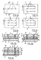
- Figure 1 shows, without limitation, several trajectories possible from a circuit capable of eliminating electrostatic charges accumulated on an outer sheet of glazing 1 according to the invention. It's about generally a transparent sheet of rigid plastic, such as acrylic, in particular polymethyl methacrylate (PMMA) polycarbonate, polyester or rigid polyurethane.
- the antistatic circuit according to the invention comprises a plurality of conductive elements 2 perpendicular to the plane of the glazing. One end of each of the elements conductors 2 is connected to a collector 3, one end of which is connected to the mass 4.
- the collector can describe only one line parallel to the plane of the glazing, as illustrated in diagram 1a. He can also describe several lines parallel to the plane of the glazing, as illustrated in diagrams 1b, 1c and 1d, each of the lines being connected to the adjacent line by one or the other of their ends, alternately, so as to form a sort of niche, as illustrated in diagram 1b. Each of the lines can also be connected to the others at one of their ends, as illustrated in diagram 1c, or at both ends, as shown in Figure 1d.
- the collector 3 forms only one circuit, connected to ground 4, connecting electrically all the conductive elements 2.
- the circuit describes a simple geometry network in order to limit the number of lines parallel to the plane of the glazing, the presence of these lines in too many numbers important which can reduce the optical quality of the glazing.
- FIG 2 shows views, according to section A-A, of the glazing shown in Figure 1a.
- These glazings include, in particular, a rigid exterior substrate 5 and a flexible plastic sheet 6.
- the flexible plastic sheets usually improve the properties of the glazing, in particular its shock absorption. These are leaves in polyvinyl butyral or flexible polyurethane. It can also be planned, in as an outer sheet, on the side of the passenger compartment, for example of a cockpit, as illustrated in diagram 2c. This sheet can confer properties of surface, such as resistance to scratching, anti-burst protection ... These are, by example, of a polyurethane sheet.
- the conductive elements 2 pass through the substrate 5 and at least part of the flexible plastic sheet 6.
- the substrate rigid outer may include an outer sheet 7, as illustrated in the diagram 2a or diagram 2b. It can also include two sheets rigid 7 and 8 between which two sheets of material are interposed flexible plastic 22 and 23.
- the glazing may comprise, in addition to the substrate 5 and the plastic sheet 6, other elements such as a rigid sheet 24, as illustrated in diagrams 2a and 2b.
- the flexible plastic sheet 6 can be formed from two sheets 6a, 6b (or more), as shown in the Figure 2b.
- Passages 9 are provided in order to pass through the elements conductors 2 through the substrate 5 and at least part of the sheet in flexible plastic material 6. These passages 9 are, for example, holes mechanically drilled.
- the outer sheet 7 is made of a stretched acrylic material which offers the advantage of resistance improved with the appearance and propagation of cracks. This characteristic is particularly advantageous insofar as several passages 9 are drilled at regular intervals. Parts of passages at leaf level flexible plastic material can be filled by creep of the material plastic when assembling the glazing.
- the electrostatic protection circuit is such that the conductive element 2 electrically connects, as soon as the circuit is installed in the glazing, the outer face 10 of the outer sheet 7 to a manifold 3 connected to ground.
- the electrostatic protection circuit according to the invention thus makes it possible to control the trajectory of the electrostatic charges present on the face 10 of sheet 7, through the glazing to the ground and this from the first use of glazing. This avoids discharges due to a difference of significant potential between face 10 and the rest of the glazing.
- the conductive element 2 can pass through an undifferentiated number of rigid and flexible sheets insofar as one of its ends is embedded in a flexible plastic sheet so that the collector either drowned in the same sheet of flexible plastic.
- the flexibility of this plastic sheet gives resistance improved mechanics to conductive elements 2 and, in particular, to collector 3.
- the collector 3 is here represented near the face 11 of a sheet flexible plastic which is the side furthest from face 12 of the outer sheet 7. This preferred arrangement improves flexibility conductors 2 and collector 3.
- the collector can be approximately in the middle of the flexible plastic sheet or at proximity of the face 12 of the outer sheet, insofar as the collector is embedded in the flexible plastic sheet and is not in contact with the rigid outer substrate.
- Figure 3 shows several enlarged views of the elements conductors 2.
- the conductive elements 2 are advantageously formed of a filament or thread.
- This filament can possibly form a loop 13 so that it constitutes a movement back and forth in the passage 9.
- This loop can possibly be twisted. It can extend beyond from the side 10 of the sheet 1 by forming a sort of wick, as shown in diagram 3a, its end may possibly be in contact with face 10. It can also be flush with the surface or be located just below, as shown in diagrams 3b and 3c.
- the collector 3 and the conductive elements 2 form only a conductive wire, as shown on the 3d diagram, which facilitates the manufacture of the protection circuit electrostatic according to the invention.
- the conductive elements and the collector are made of a material likely to conduct electricity. It can be tungsten or an alloy based on tungsten. Their diameter is, for example, of the order of 0.015 mm.
- FIGS 4 to 7 show preferred variants of the invention that the glazing comprises a heating circuit and a electrostatic protection.
- FIG. 4 represents a front view of the glazing of the invention.
- the electrostatic protection circuit shown here occupies only part of the glazing.
- the glazing comprises a substrate 5 made of polymethyl methacrylate (PMMA) and a plastic sheet 6 formed, here, of several plies of PVB and a sheet 24 in PMMA.
- the conductive elements 2 are located in the dense part of the heating network which is usually in the part glazing center. This limits any optical damage.
- the heating wires 14 and the collector 3 are located in two planes parallel, as best seen in Figures 6 and 8, so that they do not are not in contact but separated by at least part of the thickness of the flexible plastic sheet, dielectric, 6, as illustrated on the Figures 7 and 8.
- the heating circuit shown here has fine resistance wires electric 14 embedded, at least partially, in a sheet 6 of material flexible plastic. Each end of these wires is connected electrically with two collector strips 15 and 16, one of which, for example the collecting strip 15 is connected to ground, while the other, for example the collecting strip 16, is connected to a current supply source.
- the sons ends of electrical resistance 14 are advantageously located near the face 12 of the flexible plastic sheet, the face 12 constituting, in somehow, the interface with the outer sheet 7 which constitutes the substrate exterior 5: the efficiency of the heating circuit is all the more improved.
- the two collector strips are located on one side of a sheet of material flexible plastic other than the face on which the heating wires are located.
- the collector strips 15 and 16 are located on the face 11 of the sheet 6 of flexible plastic, while the heating wires 14 are located on side 17 of sheet 6 near side 12 of sheet exterior 1.
- these are turned 180 ° in the space between the strip collector 15 and the edge of the glazing.
- This reversal is shown schematically in 18.
- the fine electrical resistance wires 14 are straight in 19, while they are wavy in the central part of the glazing or, more precisely, in most of the space separating the two bands collectors 15 and 16 in order to improve their heating capacity.
- FIG. 5 illustrates, in more detail, the connection of the wires heating 14 to the collecting strip 15.
- the heating wires 14 are, usually inserted between two foils 15a and 15b forming the strip collector.
- the electrostatic protection circuit for its part, consists of conductive elements 2, electrically connected to a collector 3 located on the same face of a sheet of flexible plastic material as the collector strip 15 connected to ground.
- the collector 3 is electrically connected to the collector strip 15, for example by welding, as illustrated in FIG. 5.
- it can be connected on the face 20 or 21 of the collector strip 15.
- the configuration and position of the two circuits, the heating circuit and the antistatic circuit are such that, on the one hand, the optical quality of the glazing does not is not altered and that, on the other hand, the two circuits are isolated electrically from each other to avoid short circuits.
- the configuration and position of circuits take account of constraints and stresses that glazing can undergo in flight.
- the two circuits are nested, as seen in Figures 4, 7 and 8, the conductive elements being located between two heating wires.
- the distance between a heating wire 14 and a conductive element 2 is such that the insulation sufficient between these two materials and greater than passage diameter 9.
- the section according to FIG. 8 illustrates the inversion of the heating wires 14. This characteristic also makes it possible to heat the marginal parts of the glazing located between the edge and the collecting strip 15. Furthermore, it improves the flexibility of the heating wire and therefore its thermal resistance, in particular the temperature differences that can occur during flight.
- the conductive elements pass through the substrate comprising the rigid outer sheet 7, here constituting the substrate, and at at least part of a sheet 6 of flexible plastic.
- the substrate can also include other rigid and / or flexible sheets, such as example illustrated in Figures 1 to 3, regardless of the existence of the heating circuit.
- a flexible plastic sheet 6 comprising a heating network, fine electrical resistance wires and collector strips being on the two opposite sides of said sheet.
- This sheet is then, for example, heat-sealed with the rigid outer sheet 7.
- Passages 9 are then drilled, for example mechanically, in order to introduce the conductive elements 2.
- These are either introduced and then connected, by example welded to a collector 3 previously deposited on the sheet 6, ie a conductive filament is introduced into each of the passages by connecting them so to constitute the conducting elements 2 and the collector 3.
- One of the ends of the collector 3 is connected to ground, for example by welding. It is preferably connected to the collecting strip of the heating circuit connected to ground.
- the set consisting of sheets fitted with the circuit heating and antistatic is then assembled, possibly with other sheets forming part of the glazing.
- Sample 1 has no electrostatic protection. A perforation is observed in the thickness of the glazing for a voltage of 160 kV, corresponding to a current of the order of 300 mA / m 2, ie of the order of 80 mA for the sample tested.
- This test illustrates the critical threshold, i.e. 80 mA, not to be exceeded before to avoid any risk of discharge through the thickness of the glazing.
- Electrodes are placed 3 cm from the samples. These electrodes simulate the creation of electrostatic charges on the surface of the sheet rigid in PMMA.
- Sample 2 has three conductive elements 8 cm apart according to the configuration shown in diagrams 2b and 3d.
- Sample 3 has six conductive elements approximately 5 cm and arranged in the same configuration as sample 2.
- the conductive elements are flush with the outer surface of the sheet rigid in PMMA for the two samples.
- the intensity of the current in the conductive elements and the collector is the intensity of the current in the conductive elements and the collector.
- Measurable currents are observed from relatively voltages weak.
- the electrostatic charges are evacuated, in a way, as and as they appear. Note that the value of 80 mA is observed for voltages of 32 and 29 kV, for samples 2 and 3 respectively.
- the values obtained for the two types of protection appear relatively similar in efficiency with respect to the breakdown voltage threshold (160 kV), the voltage values being 5 to 6 times lower than the voltage slamming.
- the applied voltage has been increased for each sample in order to obtain a current of the order of 150 mA in order to test the circuit resistance for an abnormally high current.
- the two types of protection have not suffered any deterioration.
- This example illustrates the effectiveness of the protection circuit which can be relatively simple (3 conductive elements) insofar as the elements conductors are placed in the glazing area subject to these loads electrostatic.
Landscapes
- Laminated Bodies (AREA)
- Elimination Of Static Electricity (AREA)
- Surface Heating Bodies (AREA)
- Joining Of Glass To Other Materials (AREA)
Description
- la figure 1 comporte quatre schémas, 1a à 1d, représentant quatre vues de face de vitrages munis d'un circuit de protection électrostatique selon l'invention,
- la figure 2 comporte trois schémas, 2a à 2c, en coupe selon la section A-A du vitrage représenté sur le schéma 1a,
- la figure 3 comporte quatre schémas en coupe, 3a à 3d, de l'extrémité d'un élément conducteur à proximité de la face extérieure du vitrage,
- la figure 4 représente une vue d'un vitrage chauffant équipé d'un circuit antistatique selon l'invention,
- la figure 5 représente une vue partielle détaillée du vitrage de la figure 4,
- la figure 6 représente une vue, en perspective, du vitrage représenté figure 4,
- la figure 7 illustre une coupe, selon la section B-B, du vitrage représenté figure 4,
- la figure 8 illustre une coupe, selon la section C-C, du vitrage représenté figure 5.
| Échantillon 2 | Échantillon 3 | |
| Tension appliquée (kV) | Courant mesuré (mA) | Courant mesuré (mA) |
| 20 | 11 | 11 |
| 24 | 23.5 | 32.5 |
| 26 | 36 | 46 |
| 30 | 62 | 110 |
| 32 | 83.5 | 145 |
| 36 | 130 | |
| 38 | 150 |
Claims (15)
- Vitrage feuilleté (1) comprenant au moins un substrat rigide extérieur (5) et une feuille en matière plastique souple (6) adjacente au substrat comprenant une feuille extérieure (7) susceptible de se charger en charges électrostatiques, ledit vitrage étant équipé d'un circuit de protection électrostatique susceptible de dissiper les charges accumulées sur la feuille extérieure, ce circuit comprenant des éléments conducteurs (2) traversant au moins le substrat (5), ces éléments conducteurs étant connectés à un élément collecteur (3) relié à la masse, caractérisé en ce que les éléments conducteurs (2) traversent au moins une partie de la feuille en matière plastique souple dans laquelle est noyé l'élément collecteur (3).
- Vitrage selon la revendication 1, caractérisé en ce que l'élément collecteur (3) est situé dans la feuille en matière plastique souple dans un plan différent de celui constitué par l'interface entre le substrat (5) et ladite feuille en matière plastique souple (6).
- Vitrage selon la revendication 1 ou la revendication 2, caractérisé en ce que les éléments conducteurs (2) sont perpendiculaires au plan du vitrage, l'élément collecteur (3) étant parallèle au plan du vitrage.
- Vitrage selon la revendication 1, caractérisé en ce que la feuille en matière plastique souple (6) est en polyvinylbutyral.
- Vitrage selon l'une des revendications précédentes, caractérisé en ce que les éléments conducteurs (2) ne sont constitués que d'un fil ou filament conducteur.
- Vitrage selon la revendication 5, caractérisé en ce que les éléments conducteurs (2) sont constitués d'un fil ou filament formant une boucle (13) à proximité de la face (10) de la feuille extérieure sur laquelle sont susceptibles d'être présentes les charges électrostatiques.
- Vitrage selon la revendication 6, caractérisé en ce que les éléments conducteurs (2) et l'élément collecteur (3) sont constitués du même filament.
- Vitrage selon l'une des revendications précédentes, caractérisé en ce que l'élément collecteur (3) forme une ou plusieurs lignes reliées entre elles.
- Vitrage selon l'une des revendications précédentes comportant, en outre, un circuit chauffant comportant des éléments chauffants (14), caractérisé en ce que chaque élément conducteur (2) du circuit de protection électrostatique traverse le circuit chauffant.
- Vitrage selon la revendication 9, caractérisé en ce que les éléments chauffants du circuit chauffant sont des fils fins de résistance électrique (14) connectés électriquement à au moins une bande collectrice (15) reliée à la masse, chaque élément conducteur (3) du circuit de protection électrostatique passant entre deux fils fins de résistance électrique (14).
- Vitrage selon la revendication 9, caractérisé en ce que l'élément chauffant du circuit chauffant est une couche conductrice, cette couche étant dans un plan intermédiaire entre la face extérieure du vitrage et le plan contenant l'élément collecteur.
- Vitrage selon l'une des revendications 9 à 11, caractérisé en ce que l'élément collecteur (3) du circuit de protection électrostatique est connecté électriquement à la bande collectrice (15), reliée à la masse, du circuit chauffant.
- Vitrage selon l'une des revendications 9 à 12, caractérisé en ce que les éléments chauffants et la bande collectrice (15) du circuit chauffant sont situés dans deux plans différents, parallèles au plan du vitrage, des fils fins de résistance électrique étant recourbés à 180° dans l'espace séparant la bande collectrice du circuit chauffant et le bord du vitrage.
- Méthode pour fabriquer un vitrage selon l'une des revendications 1 à 13, caractérisé en ce qu'elle comprend, notamment, les étapes suivantes :l'élément collecteur étant noyé dans la feuille en matière plastique souple avant ou après l'assemblage, reliant électriquement aux éléments conducteurs et étant connecté à la masse.assemblage du substrat rigide extérieur et d'une feuille en matière plastique souple,introduction des éléments conducteurs à travers des passages aménagés préalablement dans ledit assemblage,
- Méthode selon la revendication 14, caractérisé en ce qu'on équipe une feuille en matière plastique souple d'un circuit chauffant, cette feuille entrant dans la constitution du substrat (5) ou étant ladite feuille en matière plastique souple (6) et, dans ce cas, le circuit chauffant est situé dans un plan intermédiaire entre le substrat (5) et le collecteur (3).
Applications Claiming Priority (2)
| Application Number | Priority Date | Filing Date | Title |
|---|---|---|---|
| FR9408050 | 1994-06-30 | ||
| FR9408050A FR2721857B1 (fr) | 1994-06-30 | 1994-06-30 | Vitrage equipe d'un circuit de protection electrostatique |
Publications (2)
| Publication Number | Publication Date |
|---|---|
| EP0690665A1 EP0690665A1 (fr) | 1996-01-03 |
| EP0690665B1 true EP0690665B1 (fr) | 2001-12-05 |
Family
ID=9464825
Family Applications (1)
| Application Number | Title | Priority Date | Filing Date |
|---|---|---|---|
| EP95401555A Expired - Lifetime EP0690665B1 (fr) | 1994-06-30 | 1995-06-28 | Vitrage équipé d'un circuit de protection électrostatique |
Country Status (4)
| Country | Link |
|---|---|
| US (1) | US5650208A (fr) |
| EP (1) | EP0690665B1 (fr) |
| DE (1) | DE69524301T2 (fr) |
| FR (1) | FR2721857B1 (fr) |
Families Citing this family (12)
| Publication number | Priority date | Publication date | Assignee | Title |
|---|---|---|---|---|
| FR2793106B1 (fr) * | 1999-04-28 | 2001-06-22 | Saint Gobain Vitrage | Vitrage multiple isolant, en particulier hublot d'avion, a blindage electromagnetique |
| US6180921B1 (en) * | 1999-10-08 | 2001-01-30 | Visteon Global Technologies, Inc. | Windshield heating device |
| DE10126869A1 (de) * | 2001-06-01 | 2002-12-19 | Saint Gobain Sekurit D Gmbh | Elektrisch beheizbare Scheibe |
| US7370903B2 (en) * | 2002-05-10 | 2008-05-13 | United Protective Technologies, Llc | Transparent laminated structure having peel-away film layers for use on aircraft windscreens |
| GB0216787D0 (en) * | 2002-07-19 | 2002-08-28 | Pilkington Plc | Laminated glazing panel |
| FR2882813B1 (fr) * | 2005-03-04 | 2007-05-11 | Tda Armements Sas Soc Par Acti | Structure de module pour blindage electrique |
| US7883050B2 (en) * | 2007-06-28 | 2011-02-08 | The Boeing Company | Composites with integrated multi-functional circuits |
| WO2010082970A2 (fr) * | 2008-10-23 | 2010-07-22 | University Of Virginia Patent Foundation | Blindages réactifs topologiquement contrôlés pour protection et procédé associé |
| US9266622B2 (en) | 2011-10-05 | 2016-02-23 | Textron Innovations, Inc. | Precipitation static charge drain system for an aircraft window |
| US8717734B1 (en) * | 2011-12-12 | 2014-05-06 | The Boeing Company | Dissipation of electrostatic charge from substrates |
| US9326327B2 (en) | 2013-03-15 | 2016-04-26 | Ppg Industries Ohio, Inc. | Stack including heater layer and drain layer |
| DE112022001809T5 (de) * | 2021-03-29 | 2024-01-11 | AGC Inc. | Mit einer erdungsstruktur versehenes laminiertes glas für fahrzeuge |
Family Cites Families (5)
| Publication number | Priority date | Publication date | Assignee | Title |
|---|---|---|---|---|
| US4078107A (en) * | 1976-06-28 | 1978-03-07 | Ppg Industries, Inc. | Lightweight window with heating circuit and anti-static circuit and a method for its preparation |
| US4590535A (en) * | 1983-02-04 | 1986-05-20 | Ppg Industries, Inc. | Static charge dissipation circuit with electroconductive wicks |
| US4920254A (en) * | 1988-02-22 | 1990-04-24 | Sierracin Corporation | Electrically conductive window and a method for its manufacture |
| FR2656491B1 (fr) * | 1989-12-21 | 1996-06-07 | Saint Gobain Vitrage Int | Vitrage chauffant. |
| DE4207638C2 (de) * | 1992-03-11 | 1994-01-27 | Ver Glaswerke Gmbh | Heizbare Verbundglasscheibe mit in der thermoplastischen Zwischenschicht angeordneten Widerstandsdrähten |
-
1994
- 1994-06-30 FR FR9408050A patent/FR2721857B1/fr not_active Expired - Lifetime
-
1995
- 1995-06-26 US US08/494,876 patent/US5650208A/en not_active Expired - Lifetime
- 1995-06-28 EP EP95401555A patent/EP0690665B1/fr not_active Expired - Lifetime
- 1995-06-28 DE DE69524301T patent/DE69524301T2/de not_active Expired - Lifetime
Also Published As
| Publication number | Publication date |
|---|---|
| US5650208A (en) | 1997-07-22 |
| FR2721857A1 (fr) | 1996-01-05 |
| EP0690665A1 (fr) | 1996-01-03 |
| DE69524301D1 (de) | 2002-01-17 |
| DE69524301T2 (de) | 2002-10-31 |
| FR2721857B1 (fr) | 1996-09-06 |
Similar Documents
| Publication | Publication Date | Title |
|---|---|---|
| CA2469708C (fr) | Vitre chauffante avec un revetement superficiel electriquement conducteur | |
| EP2419787B1 (fr) | Dispositif électrochrome à transparence contrôlée | |
| CA2142984C (fr) | Vitrage a proprietes ameliorees | |
| EP0690665A1 (fr) | Vitrage équipé d'un circuit de protection électrostatique | |
| FR2909921A1 (fr) | Vitrage fonctionnalise | |
| EP1559296B1 (fr) | Vitre transparente avec surface de contact non transparente pour une liaison par brasage | |
| WO2003056880A2 (fr) | Vitre feuilletee avec un element fonctionnel a commande electrique | |
| EP1340060A1 (fr) | Procede de fabrication de convertisseurs thermo-electriques | |
| EP0893938B1 (fr) | Vitrage chauffant feuilleté, notamment pour cockpit d'avion | |
| CA2962211C (fr) | Vitrage chauffant et de blindage electromagnetique | |
| EP3803018A1 (fr) | Vitrage ayant des performances acoustiques ameliorées | |
| EP0434537B1 (fr) | Vitrage chauffant | |
| EP0506521B1 (fr) | Vitrage feuilleté chauffant | |
| LU86892A1 (fr) | Vitrages comprenant une feuille de verre qui porte un reveement conducteur | |
| FR2721759A1 (fr) | Connecteur électrique hermétique. | |
| FR3146873A1 (fr) | Vitrage feuilleté aéronautique à système de chauffage électrique, utilisation du vitrage feuilleté aéronautique comme vitrage de cockpit d’aéronef, et aéronef associé | |
| EP3723982B1 (fr) | Vitrage chauffant en matière plastique structurale | |
| FR2819942A1 (fr) | Dispositif pour contact electrique pour materiaux fibreux et son uitilisation pour le chauffage par effet joule | |
| FR2875215A1 (fr) | Procede de realisation d'une protection externe d'un vecteur et vecteur dote d'une telle protection. | |
| FR2782944A1 (fr) | Dispositif de localisation d'une rupture dans un panneau transparent a au moins deux plis et panneau obtenu | |
| FR2893177A1 (fr) | Cable electrique avec ecran ameliore |
Legal Events
| Date | Code | Title | Description |
|---|---|---|---|
| PUAI | Public reference made under article 153(3) epc to a published international application that has entered the european phase |
Free format text: ORIGINAL CODE: 0009012 |
|
| AK | Designated contracting states |
Kind code of ref document: A1 Designated state(s): CH DE GB IT LI |
|
| 17P | Request for examination filed |
Effective date: 19960214 |
|
| GRAG | Despatch of communication of intention to grant |
Free format text: ORIGINAL CODE: EPIDOS AGRA |
|
| 17Q | First examination report despatched |
Effective date: 20001213 |
|
| RAP1 | Party data changed (applicant data changed or rights of an application transferred) |
Owner name: SAINT-GOBAIN GLASS FRANCE |
|
| GRAG | Despatch of communication of intention to grant |
Free format text: ORIGINAL CODE: EPIDOS AGRA |
|
| GRAH | Despatch of communication of intention to grant a patent |
Free format text: ORIGINAL CODE: EPIDOS IGRA |
|
| GRAG | Despatch of communication of intention to grant |
Free format text: ORIGINAL CODE: EPIDOS AGRA |
|
| GRAH | Despatch of communication of intention to grant a patent |
Free format text: ORIGINAL CODE: EPIDOS IGRA |
|
| GRAH | Despatch of communication of intention to grant a patent |
Free format text: ORIGINAL CODE: EPIDOS IGRA |
|
| GRAA | (expected) grant |
Free format text: ORIGINAL CODE: 0009210 |
|
| AK | Designated contracting states |
Kind code of ref document: B1 Designated state(s): CH DE GB IT LI |
|
| REG | Reference to a national code |
Ref country code: CH Ref legal event code: EP |
|
| REG | Reference to a national code |
Ref country code: GB Ref legal event code: IF02 |
|
| REF | Corresponds to: |
Ref document number: 69524301 Country of ref document: DE Date of ref document: 20020117 |
|
| REG | Reference to a national code |
Ref country code: CH Ref legal event code: NV Representative=s name: KIRKER & CIE SA |
|
| GBT | Gb: translation of ep patent filed (gb section 77(6)(a)/1977) |
Effective date: 20020220 |
|
| PLBE | No opposition filed within time limit |
Free format text: ORIGINAL CODE: 0009261 |
|
| STAA | Information on the status of an ep patent application or granted ep patent |
Free format text: STATUS: NO OPPOSITION FILED WITHIN TIME LIMIT |
|
| 26N | No opposition filed | ||
| PGFP | Annual fee paid to national office [announced via postgrant information from national office to epo] |
Ref country code: GB Payment date: 20140625 Year of fee payment: 20 |
|
| PGFP | Annual fee paid to national office [announced via postgrant information from national office to epo] |
Ref country code: DE Payment date: 20140625 Year of fee payment: 20 Ref country code: IT Payment date: 20140620 Year of fee payment: 20 Ref country code: CH Payment date: 20140612 Year of fee payment: 20 |
|
| REG | Reference to a national code |
Ref country code: DE Ref legal event code: R071 Ref document number: 69524301 Country of ref document: DE |
|
| REG | Reference to a national code |
Ref country code: CH Ref legal event code: PL |
|
| REG | Reference to a national code |
Ref country code: GB Ref legal event code: PE20 Expiry date: 20150627 |
|
| PG25 | Lapsed in a contracting state [announced via postgrant information from national office to epo] |
Ref country code: GB Free format text: LAPSE BECAUSE OF EXPIRATION OF PROTECTION Effective date: 20150627 |