EP0689821B1 - Absorbent catamenial device - Google Patents
Absorbent catamenial device Download PDFInfo
- Publication number
- EP0689821B1 EP0689821B1 EP95109135A EP95109135A EP0689821B1 EP 0689821 B1 EP0689821 B1 EP 0689821B1 EP 95109135 A EP95109135 A EP 95109135A EP 95109135 A EP95109135 A EP 95109135A EP 0689821 B1 EP0689821 B1 EP 0689821B1
- Authority
- EP
- European Patent Office
- Prior art keywords
- pad
- section
- insert
- adhesive zones
- width
- Prior art date
- Legal status (The legal status is an assumption and is not a legal conclusion. Google has not performed a legal analysis and makes no representation as to the accuracy of the status listed.)
- Expired - Lifetime
Links
- 239000002250 absorbent Substances 0.000 title claims description 14
- 230000002745 absorbent Effects 0.000 title claims description 13
- 239000000853 adhesive Substances 0.000 claims description 32
- 230000001070 adhesive effect Effects 0.000 claims description 32
- 230000002175 menstrual effect Effects 0.000 description 12
- 239000012530 fluid Substances 0.000 description 5
- 239000007788 liquid Substances 0.000 description 2
- 238000000034 method Methods 0.000 description 2
- 239000004831 Hot glue Substances 0.000 description 1
- 206010021639 Incontinence Diseases 0.000 description 1
- 239000011230 binding agent Substances 0.000 description 1
- 230000007423 decrease Effects 0.000 description 1
- 238000006073 displacement reaction Methods 0.000 description 1
- 230000002093 peripheral effect Effects 0.000 description 1
- 230000037074 physically active Effects 0.000 description 1
- 230000001681 protective effect Effects 0.000 description 1
Images

Classifications
-
- A—HUMAN NECESSITIES
- A61—MEDICAL OR VETERINARY SCIENCE; HYGIENE
- A61F—FILTERS IMPLANTABLE INTO BLOOD VESSELS; PROSTHESES; DEVICES PROVIDING PATENCY TO, OR PREVENTING COLLAPSING OF, TUBULAR STRUCTURES OF THE BODY, e.g. STENTS; ORTHOPAEDIC, NURSING OR CONTRACEPTIVE DEVICES; FOMENTATION; TREATMENT OR PROTECTION OF EYES OR EARS; BANDAGES, DRESSINGS OR ABSORBENT PADS; FIRST-AID KITS
- A61F13/00—Bandages or dressings; Absorbent pads
- A61F13/15—Absorbent pads, e.g. sanitary towels, swabs or tampons for external or internal application to the body; Supporting or fastening means therefor; Tampon applicators
- A61F13/56—Supporting or fastening means
- A61F13/5605—Supporting or fastening means specially adapted for sanitary napkins or the like
- A61F13/5611—Supporting or fastening means specially adapted for sanitary napkins or the like using fastening strips, e.g. adhesive, on the undergarment-facing side
Definitions
- the present invention relates to an absorbent insert and especially an absorbent pad that acts as a menstrual pad, an incontinence pad and the like is.
- Conventional absorbent pads such as menstrual pads or binders have a fastening device that is arranged on its back so that the insert on the Panties are attached by the fastener can and therefore also during active body movements of the Carrier are kept at their target position.
- a fastening device that is arranged on its back so that the insert on the Panties are attached by the fastener can and therefore also during active body movements of the Carrier are kept at their target position.
- Japanese Utility Model Application Laid-Open No. 1984-177425 a technique according to which a dimension in the transverse direction of a fastening device in Longitudinal direction from at least one end to the central region of one Menstrual insert is gradually reduced.
- a such fastener acts in the same way like the attachment zones.
- the panties often not in close contact with the wearer's body is, especially in an area from crotch to hip runs, and in addition the hip often other objects, such as for example brushes a chair on which the wearer sits.
- the insert it is often difficult for the insert to be between the panties and the body area of the wearer is held.
- an active movement of the wearer's body can shift the insert relative to the wearer's panties and the shifted insert makes the wearer uncomfortable Feeling, especially in the hip area, and dirty the wearer's body and clothing with menstrual fluid. This also teaches with regard to this problem the aforementioned application is not an effective solution.
- An absorbent insert is also described from WO-A-92/04000, which has adhesive strips for fixing, the Adhesive strips arranged side by side in the transverse direction and from the front section to the middle section run to the rear section of the insert.
- the in Transverse direction measured distance of the adjacent adhesive strips is in the middle section of the insert less than in the front or rear section.
- the holding force of the adhesive strips dimensioned so that the used insert is pulled off the panties is possible.
- the disadvantage of this is that the insert move slightly when the wearer is physically active can.
- the invention is therefore based on the object of a deposit to create the type described above, the one hand can be securely fixed and on the other hand by the wearer can be easily removed.
- an absorbent insert comprising a liquid-permeable Top layer, a liquid-impermeable outer layer, a liquid absorbent arranged between these two layers Core and a fastener attached to it the outer layer is intended to attach the insert to the panties is, wherein the fastening device comprises adhesive zones, the along opposite sides in the transverse direction the insert are provided, one between outer edges the adhesive zones opposite each other in the transverse direction measured dimension in a longitudinal front and rear section of the insert is larger than in an in Longitudinal middle section of the insert and one for peeling the insert required force in the rear section is higher than in the other sections.
- a menstrual pad 1 comprises one liquid-permeable top layer 2, a liquid-impermeable Outer layer 3 and a liquid absorbent Core 4, which is arranged between these two layers 2, 3, with sections of the top and outer layers 2, 3, which are extend outwards over a peripheral edge of the core 4, together waterproof along a connecting line 5 are connected.
- the back of the insert 1, which for Putting on the worn panties is intended with two Provide adhesive zones that form a fastening device, the with hot melt adhesive on the outer layer 3 in the form of Stripes, tapes or webs are applied.
- Adhesive zones 7, 8 extend longitudinally from the front section 11 to the rear section 12, describing circular arcs that are convex with respect to a center line (not shown) that divides the insert 1 in the transverse direction into right and left halves.
- a dimension "D" measured between the outer edges of the respective adhesive zones 7, 8 is relatively large in the front and rear sections 11, 12 and gradually reduced to a minimum in the middle section 13.
- a dimension "d” measured between the inner edges also gradually decreases to a minimum in the central section 13.
- a width W C in the rear section 12 is larger than widths W A , W B in the front or middle section.
- Such a configuration of the adhesive zones 7, 8 allows the insert 1 to be attached to the panties along the right and left side edges around the wearer's legs symmetrically with respect to the crotch area.
- a surface of the adhesive zones 7, 8 on the surface of the insert 1, which is intended to be placed on the worn panties, can be dimensioned such that it is larger in the rear section 12 than in the front and in the middle section 11, 13.
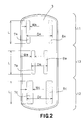
- adhesive zones are divided along transverse side edges of the insert 1 into three straight zones 7 A , 7 B , 7 C and 8 A , 8 B , 8 C with substantially the same length "L", which occupy the front, middle and rear sections 11, 13, 12 of the insert 1.
- the mutually opposite adhesive zones are arranged parallel to one another at a distance, with the width W A in the front section 11, W B in the middle section 13 and W C in the rear section 12, W C being greater than W A and W B, respectively is.
- the respective pairs of mutually opposite adhesive zones are spaced apart from one another by the width D A , D B , D C in the front, middle and rear sections 11, 13, 12, where D A is essentially equal to D C , but D B is smaller than D A and D C. Accordingly, the total area of the adhesive zones in the rear section 12 is larger than in the front and in the middle section 11, 13, and a force required to separate the same is correspondingly higher than in the front and in the middle section 11, 13.
- FIGS. 1 and 2 The one required for severing in the rear section 12 Force that is ensured by the arrangement that is in Form of an example is shown by FIGS. 1 and 2 preferably at least 1.2 times this force in the front Section 11.
- the insert 1 according to the invention can be worn that the middle section 13, the minimum dimension "D" between has the outer edges of the adhesive zones 7, 8, in Crotch area is positioned, and the rear section 12 is positioned on the hip area of the panties.
- the Insert 1 is thus directional in the longitudinal direction and preferably provided with suitable facilities that the Carrier identifying this particular direction of Make insert 1 easier.
- the deposit 1 is in the trade Consumers with protective paper covered by release paper Adhesive zones 7, 8 supplied.
- the adhesive can be on the zones 7, 8 are so applied that flat courses, points or broken lines are formed.
- the Dimension "d" between the inner edges of the adhesive zones 7, 8 is measured, is preferably to 10 millimeters or larger and more preferred to 15 millimeters or larger set to prevent the adhesive zones 7, 8 be glued together.
- panties can be used not only around the crotch area, but also along the side edges of the leg openings be fastened near the crotch area without the fear that the deposit will remain active Movement of the wearer's body could be twisted there those between the outer edges of the crosswise to each other opposite adhesive zones measured dimension in the in Longitudinal front and rear section is larger than in the longitudinal middle section of the napkin.
- the pad caused by menstrual fluid was dirty, easily from the panties towards the front to the rear section, since the to Separating the insert required force is set so that it is higher in the rear section than in the front and in the middle section of the bandage.
- This feature of the invention effectively stabilizes the rear section the insert against active movement of the wearer's body or sitting down and getting up often Chair. In this way, the insert according to the invention is comfortable to wear and hardly pollutes the body or the Clothing of the wearer.
Landscapes
- Health & Medical Sciences (AREA)
- Epidemiology (AREA)
- Engineering & Computer Science (AREA)
- Biomedical Technology (AREA)
- Heart & Thoracic Surgery (AREA)
- Vascular Medicine (AREA)
- Life Sciences & Earth Sciences (AREA)
- Animal Behavior & Ethology (AREA)
- General Health & Medical Sciences (AREA)
- Public Health (AREA)
- Veterinary Medicine (AREA)
- Absorbent Articles And Supports Therefor (AREA)
- Orthopedics, Nursing, And Contraception (AREA)
- Vehicle Interior And Exterior Ornaments, Soundproofing, And Insulation (AREA)
Description
Die vorliegende Erfindung betrifft eine saugfähige Einlage und insbesondere eine saugfähige Einlage, die als eine Menstruationseinlage, eine Inkontinenzeinlage und ähnliches geeignet ist.The present invention relates to an absorbent insert and especially an absorbent pad that acts as a menstrual pad, an incontinence pad and the like is.
Herkömmliche saugfähige Einlagen, wie etwa Menstruationseinlagen bzw. Binden, haben eine Befestigungseinrichtung, die auf ihrer Rückseite angeordnet ist, so daß die Einlage an dem Höschen durch die Befestigungseinrichtung befestigt werden kann und dadurch auch während aktiver Körperbewegungen der Trägerin an ihrer Zielposition gehalten werden. Beispielsweise zeigt die japanische offengelegte Gebrauchsmusteranmeldung Nr. 1984-177425 eine Technik auf, gemäß welcher eine Abmessung in Querrichtung einer Befestigungseinrichtung in Längsrichtung von wenigstens einem Ende zum Mittelbereich einer Menstruationseinlage hin allmählich verringert wird. Eine derartige Befestigungseinrichtung wirkt in derselben Weise wie die Befestigungszonen.Conventional absorbent pads, such as menstrual pads or binders have a fastening device that is arranged on its back so that the insert on the Panties are attached by the fastener can and therefore also during active body movements of the Carrier are kept at their target position. For example shows the Japanese Utility Model Application Laid-Open No. 1984-177425 a technique according to which a dimension in the transverse direction of a fastening device in Longitudinal direction from at least one end to the central region of one Menstrual insert is gradually reduced. A such fastener acts in the same way like the attachment zones.
Wenn eine relative Position einer Menstruationseinlage und des Höschens der Trägerin sich bedingt durch die Bewegung der Trägerin verschiebt, kann die Einlage verdreht oder gefaltet werden, was nicht nur ein unkomfortables Tragegefühl verursacht, sondern auch das teilweise Herausragen der Einlage aus dem Höschen, wobei die Bekleidung mit Menstruationsflüssigkeit verschmiert werden kann. Ein derartiges Problem tritt wahrscheinlich im Schrittbereich des Höschens auf. Die in der vorstehend genannten Anmeldung aufgezeigte Einlage schlägt sicherlich die Befestigungseinrichtung vor, lehrt jedoch keine effektive Lösung dieses Problems. Gemäß dieser bekannten Technik wird eine Haltekraft der Befestigungseinrichtung so eingestellt, daß sie das Trennen bzw. das Abziehen der benutzten Einlage, die mit Menstruationsflüssigkeit verschmutzt ist, von dem Höschen erlaubt. Es ist jedoch der Fall, daß das Höschen oftmals nicht in engem Kontakt mit dem Körper der Trägerin ist, insbesondere in einem Bereich, der vom Schritt zur Hüfte verläuft, und zusätzlich die Hüfte häufig andere Objekte, wie etwa einen Stuhl streift, auf welchem die Trägerin sitzt. Folglich ist es oftmals schwierig, daß die Einlage zwischen dem Höschen und dem Körperbereich der Trägerin gehalten wird. Insbesondere eine aktive Bewegung des Körpers der Trägerin kann die Einlage relativ zu dem Höschen der Trägerin verschieben und die verschobene Einlage gibt der Trägerin ein unkomfortables Gefühl, insbesondere im Hüftbereich, und verschmutzt den Körper der Trägerin sowie die Kleidung mit Menstruationsflüssigkeit. Auch im Hinblick auf dieses Problem lehrt die vorstehend genannte Anmeldung keine wirksame Lösung.If a relative position of a menstrual pad and of the wearer's panties is caused by the movement of the If the wearer moves, the insert can be twisted or folded which not only causes an uncomfortable feeling, but also the partial protrusion of the insert the panties, the clothing with menstrual fluid can be smeared. Such a problem is likely to occur in the crotch area of the panties. The above The deposit shown above certainly surely beats the fastener, but does not teach effective solution to this problem. According to this known technique a holding force of the fastening device is set so that they used separating or peeling off Pad soiled with menstrual fluid from allowed the panties. However, it is the case that the panties often not in close contact with the wearer's body is, especially in an area from crotch to hip runs, and in addition the hip often other objects, such as for example brushes a chair on which the wearer sits. As a result, it is often difficult for the insert to be between the panties and the body area of the wearer is held. In particular, an active movement of the wearer's body can shift the insert relative to the wearer's panties and the shifted insert makes the wearer uncomfortable Feeling, especially in the hip area, and dirty the wearer's body and clothing with menstrual fluid. This also teaches with regard to this problem the aforementioned application is not an effective solution.
Aus WO-A-92/04000 ist ebenfalls eine saugfähige Einlage beschrieben, die zur Fixierung Klebestreifen aufweist, wobei die Klebestreifen in Querrichtung nebeneinanderliegend angeordnet sind und von dem vorderen Abschnitt über den mittleren Abschnitt zum hinteren Abschnitt der Einlage verlaufen. Der in Querrichtung gemessene Abstand der nebeneinanderliegenden Klebestreifen ist hierbei in dem mittleren Abschnitt der Einlage geringer als in dem vorderen oder hinteren Abschnitt. Auch bei dieser bekannten Einlage ist die Haltekraft der Klebestreifen so bemessen, daß ein Abziehen der benutzten Einlage vom Höschen möglich ist. Nachteilig ist hieran, daß sich die Einlage bei körperlicher Aktivität der Trägerin leicht verschieben kann.An absorbent insert is also described from WO-A-92/04000, which has adhesive strips for fixing, the Adhesive strips arranged side by side in the transverse direction and from the front section to the middle section run to the rear section of the insert. The in Transverse direction measured distance of the adjacent adhesive strips is in the middle section of the insert less than in the front or rear section. Also at this known insert is the holding force of the adhesive strips dimensioned so that the used insert is pulled off the panties is possible. The disadvantage of this is that the insert move slightly when the wearer is physically active can.
Der Erfindung liegt also die Aufgabe zugrunde, eine Einlage der vorstehend beschriebenen Art zu schaffen, die sich einerseits sicher fixieren läßt und andererseits von der Trägerin leicht entfernt werden kann.The invention is therefore based on the object of a deposit to create the type described above, the one hand can be securely fixed and on the other hand by the wearer can be easily removed.
Die Lösung der Aufgabe ergibt sich aus Patentanspruch 1. Unteransprüche
zeigen bevorzugte Ausführungsformen der Erfindung.The solution to the problem results from
Erfindungsgemäß wird die vorstehend dargelegte Aufgabe durch eine saugfähige Einlage gelöst, umfassend eine flüssigkeitsdurchlässige Decklage, eine flüssigkeitsundurchlässige Außenlage, einen zwischen diesen beiden Lagen angeordneten flüssigkeitssaugfähigen Kern und eine Befestigungseinrichtung, die an der Außenlage zur Befestigung der Einlage am Höschen vorgesehen ist, wobei die Befestigungseinrichtung Klebezonen umfaßt, die entlang in Querrichtung einander gegenüberliegenden Seiten der Einlage vorgesehen sind, wobei eine zwischen äußeren Rändern der in Querrichtung einander gegenüberliegenden Klebezonen gemessene Abmessung in einem in Längsrichtung vorderen und hinteren Abschnitt der Einlage größer ist als in einem in Längsrichtung mittleren Abschnitt der Einlage und eine zum Abziehen der Einlage erforderliche Kraft in dem hinteren Abschnitt höher ist als in den übrigen Abschnitten.According to the invention, the object set out above is achieved by dissolved an absorbent insert, comprising a liquid-permeable Top layer, a liquid-impermeable outer layer, a liquid absorbent arranged between these two layers Core and a fastener attached to it the outer layer is intended to attach the insert to the panties is, wherein the fastening device comprises adhesive zones, the along opposite sides in the transverse direction the insert are provided, one between outer edges the adhesive zones opposite each other in the transverse direction measured dimension in a longitudinal front and rear section of the insert is larger than in an in Longitudinal middle section of the insert and one for peeling the insert required force in the rear section is higher than in the other sections.
Die Einlage mit diesem Aufbau kann zuverlässig durch die Befestigungseinrichtung
am Höschen nicht nur um den Schrittbereich,
sondern auch entlang den Seitenrändern von Beinöffnungen
in Längsrichtung im vorderen und hinteren Bereich des
Schrittbereiches befestigt werden. Auf diese Weise wird der in
Längsrichtung hintere Abschnitt der Einlage in ausreichender
Weise gegen die Hüfte des Höschens stabilisiert, um sicherzustellen,
daß auch eine aktive Bewegung des Körpers der Trägerin
keine Verschiebung der Einlage verursacht und daß die Einlage,
die durch Menstruationsflüssigkeit verschmutzt
wurde, von den Höschen leicht abgezogen werden kann, beginnend
von dem vorderen Abschnitt, in welchem die Klebekraft
relativ schwach ist.
Wie Fig. 1 zeigt, umfaßt eine Menstruationseinlage 1 eine
flüssigkeitsdurchlässige Decklage 2, eine flüssigkeitsundurchlässige
Außenlage 3 und einen flüssigkeitssaugfähigen
Kern 4, der zwischen diesen beiden Lagen 2, 3 angeordnet ist,
wobei Abschnitte der Deck- und der Außenlage 2, 3, die sich
über einen Umfangsrand des Kernes 4 hinaus nach außen erstrecken,
miteinander entlang einer Verbindungslinie 5 wasserdicht
verbunden sind. Die Rückseite der Einlage 1, die zum
Anlegen an das getragene Höschen bestimmt ist, ist mit zwei
Klebezonen versehen, die eine Befestigungseinrichtung bilden,
die mit Heißschmelzkleber an der Außenlage 3 in Form von
Streifen, Bändern oder Bahnen aufgetragen ist.As shown in FIG. 1, a
Es sei angenommen, daß die Einlage 1 in Längsrichtung in
einen vorderen Abschnitt 11, einen Mittelabschnitt 13 und
einen hinteren Abschnitt 12 eingeteilt ist. Klebezonen 7, 8
erstrecken sich in Längsrichtung vom vorderen Abschnitt 11
zum hinteren Abschnitt 12, wobei sie kreisförmige Bögen beschreiben,
die bezüglich einer Mittellinie (nicht dargestellt),
die die Einlage 1 in Querrichtung in eine rechte und
eine linke Hälfte unterteilt, konvex sind. Eine Abmessung
"D", gemessen zwischen den äußeren Rändern der jeweiligen
Klebezonen 7, 8, ist in dem vorderen und dem hinteren Abschnitt
11, 12 relativ groß und in dem mittleren Abschnitt 13
allmählich auf ein Minimum verringert. Eine Abmessung "d",
die zwischen den Innenrändern gemessen wird, verringert sich
ebenfalls in dem mittleren Abschnitt 13 allmählich auf ein
Minimum. In jeder der Klebezonen 7, 8 ist eine Breite WC im
hinteren Abschnitt 12 größer als Breiten WA, WB im vorderen
bzw. mittleren Abschnitt. Eine derartige Konfiguration der
Klebezonen 7, 8 erlaubt es, die Einlage 1 an dem Höschen entlang
dem rechten und dem linken Seitenrand um die Beine der
Trägerin symmetrisch bezüglich des Schrittbereichs zu befestigen.
Eine Fläche der Klebezonen 7, 8 auf der Oberfläche
der Einlage 1, die zum Anlegen an das getragene Höschen bestimmt
ist, kann so dimensioniert sein, daß sie im hinteren
Abschnitt 12 größer ist als im vorderen und im mittleren Abschnitt
11, 13.It is assumed that the
Wie Fig. 2 zeigt, sind Klebezonen entlang in Querrichtung
einander gegenüberliegenden Seitenrändern der Einlage 1 jeweils
in drei gerade Zonen 7A, 7B, 7C und 8A, 8B, 8C mit im
wesentlichen derselben Länge "L" unterteilt, welche den vorderen,
mittleren und hinteren Abschnitt 11, 13, 12 der Einlage
1 einnehmen. Die in Querrichtung einander gegenüberliegenden
Klebezonen sind parallel zueinander im Abstand angeordnet,
mit der Breite WA in dem vorderen Abschnitt 11, WB in
dem Mittelabschnitt 13 und WC in dem hinteren Abschnitt 12,
wobei WC größer als WA bzw. WB ist.As shown in FIG. 2, adhesive zones are divided along transverse side edges of the
Die jeweiligen Paare von in Querrichtung einander gegenüberliegenden
Klebezonen sind voneinander durch die Breite DA,
DB, DC im vorderen, mittleren bzw. hinteren Abschnitt 11, 13,
12 beabstandet, wobei DA im wesentlichen gleich DC ist, DB
jedoch kleiner ist als DA und DC. Demgemäß ist die Gesamtfläche
der Klebezonen in dem hinteren Abschnitt 12 größer als im
vorderen und im mittleren Abschnitt 11, 13, und eine zum Abtrennen
derselben erforderliche Kraft entsprechend höher als
im vorderen und im mittleren Abschnitt 11, 13. Alternativ ist
es möglich, alle Klebezonen so zu dimensionieren, daß sie
gleiche Flächen haben, und eine Klebkraft des Klebstoffs in
den Zonen 7C, 8C so einzustellen, daß sie höher ist als in
den Zonen 7A, 7B, 8A, 8B, so daß eine zum Abtrennen im hinteren
Abschnitt 12 erforderliche Kraft so eingestellt werden
kann, daß sie höher als in den anderen Abschnitten ist.The respective pairs of mutually opposite adhesive zones are spaced apart from one another by the width D A , D B , D C in the front, middle and
Die zum Abtrennen in dem hinteren Abschnitt 12 erforderliche
Kraft, die durch die Anordnung sichergestellt wird, die in
Form eines Beispiels durch Fig. 1 und 2 dargestellt wird, ist
vorzugsweise wenigstens das 1,2-fache dieser Kraft im vorderen
Abschnitt 11.The one required for severing in the
Die Einlage 1 gemäß der Erfindung kann so getragen werden,
daß der Mittelabschnitt 13, der die Mindestabmessung "D" zwischen
den äußeren Rändern der Klebezonen 7, 8 hat, im
Schrittbereich positioniert ist, und der hintere Abschnitt 12
jeweils am Hüftbereich des Höschens positioniert ist. Die
Einlage 1 ist somit in Längsrichtung richtungsgebunden und
vorzugsweise mit geeigneten Einrichtungen versehen, die der
Trägerin die Identifizierung dieser bestimmten Richtung der
Einlage 1 erleichtern. Die Einlage 1 wird im Handel dem
Verbraucher mit durch Trennpapier schützend abgedeckten
Klebezonen 7, 8 geliefert. Der Klebstoff kann auf die Zonen
7, 8 so aufgetragen werden, daß flächige Verläufe, Punkte
oder unterbrochen angeordnete Linien gebildet werden. Die
Abmessung "d", die zwischen den Innenrändern der Klebezonen
7, 8 gemessen wird, wird vorzugsweise auf 10 Millimeter oder
größer und bevorzugter auf 15 Millimeter oder größer
eingestellt, um zu verhindern, daß die Klebezonen 7, 8
miteinander verklebt werden.The
Eine Einlage, wie beispielsweise die Menstruationseinlage gemäß der Erfindung, kann an Höschen nicht nur um den Schrittbereich, sondern auch entlang den Seitenrändern der Beinöffnungen in der Nähe des Schrittbereichs befestigt werden, ohne der Befürchtung, daß die Einlage auch während einer aktiven Bewegung des Körpers der Trägerin verdreht werden könnte, da die zwischen den äußeren Rändern der in Querrichtung einander gegenüberliegenden Klebezonen gemessene Abmessung in dem in Längsrichtung vorderen und hinteren Abschnitt größer ist als in dem in Längsrichtung mittleren Abschnitt der Binde. Zusätzlich kann die Einlage, die durch Menstruationsflüssigkeit verschmutzt wurde, problemlos von dem Höschen in Richtung vom vorderen zum hinteren Abschnitt abgezogen werden, da die zum Trennen der Einlage erforderliche Kraft so eingestellt ist, daß sie im hinteren Abschnitt höher ist als im vorderen und im mittleren Abschnitt der Binde. Dieses Merkmal der Erfindung stabilisiert in effektiver Weise den hinteren Abschnitt der Einlage gegen eine aktive Bewegung des Körpers der Trägerin oder häufiges Hinsetzen auf und Aufstehen von einem Stuhl. Auf diese Weise ist die erfindungsgemäße Einlage komfortabel zu tragen und verschmutzt kaum den Körper oder die Kleidung der Trägerin.An insert, such as the menstrual insert according to of the invention, panties can be used not only around the crotch area, but also along the side edges of the leg openings be fastened near the crotch area without the fear that the deposit will remain active Movement of the wearer's body could be twisted there those between the outer edges of the crosswise to each other opposite adhesive zones measured dimension in the in Longitudinal front and rear section is larger than in the longitudinal middle section of the napkin. In addition can the pad caused by menstrual fluid was dirty, easily from the panties towards the front to the rear section, since the to Separating the insert required force is set so that it is higher in the rear section than in the front and in the middle section of the bandage. This feature of the invention effectively stabilizes the rear section the insert against active movement of the wearer's body or sitting down and getting up often Chair. In this way, the insert according to the invention is comfortable to wear and hardly pollutes the body or the Clothing of the wearer.
Claims (4)
- Absorbent pad, comprising a liquid-permeable cover layer (2), a liquid-impermeable outer layer (3), a liquid-absorbent core (4) and a fastening device, which is provided on the outer layer (3) to fasten the pad to the pants, the fastening device comprising adhesive zones (7, 8) which are provided on sides of the pad lying opposite one another in a transverse direction, and a dimension (D), measured between outer edges of the adhesive zones lying opposite one another in a transverse direction, being greater in a front and rear section (11, 12) in the longitudinal direction of the pad than in a central section (13) in the longitudinal direction of the pad,
characterised in that
the force necessary to pull away the pad is greater in the rear section (12) than in the remaining sections. - Absorbent pad according to claim 1,
characterised in that
a measured dimension (d) between inner side edges of the adhesive zones (7,8) is smaller in the central section than in the front section (11) and the rear section (12). - Absorbent pad according to claim 1,
characterised in that
the adhesive zones (7,8) describe circular arcs, which are convex in respect of a central line, which divides the pad in the transverse direction. - Absorbent pad according to claim 1,
characterised in that
the adhesive zones are respectively divided in three straight zones (7A, tB, 7C, 8A, 8B, 8C) of essentially the same length which take up the front, the central and the rear sections (11, 13, 12), and in that the adhesive zones (7A, tB, 7C, 8A, 8B, 8C), which lie opposite one another in the transverse direction, are parallel and spaced from one another by a first width in the front section (11), a second width in the central section (13) and a third width in the rear section (12), the third width being greater than the first width and the second width.
Applications Claiming Priority (3)
| Application Number | Priority Date | Filing Date | Title |
|---|---|---|---|
| JP6131973A JPH07328068A (en) | 1994-06-14 | 1994-06-14 | Sanitary napkin |
| JP131973/94 | 1994-06-14 | ||
| JP13197394 | 1994-06-14 |
Publications (3)
| Publication Number | Publication Date |
|---|---|
| EP0689821A2 EP0689821A2 (en) | 1996-01-03 |
| EP0689821A3 EP0689821A3 (en) | 1997-01-08 |
| EP0689821B1 true EP0689821B1 (en) | 2000-02-09 |
Family
ID=15070563
Family Applications (1)
| Application Number | Title | Priority Date | Filing Date |
|---|---|---|---|
| EP95109135A Expired - Lifetime EP0689821B1 (en) | 1994-06-14 | 1995-06-13 | Absorbent catamenial device |
Country Status (9)
| Country | Link |
|---|---|
| EP (1) | EP0689821B1 (en) |
| JP (1) | JPH07328068A (en) |
| KR (1) | KR0122116Y1 (en) |
| CN (1) | CN2242680Y (en) |
| AU (1) | AU687179B2 (en) |
| CA (1) | CA2151437C (en) |
| DE (1) | DE59507767D1 (en) |
| MY (1) | MY130603A (en) |
| TW (1) | TW294962U (en) |
Cited By (7)
| Publication number | Priority date | Publication date | Assignee | Title |
|---|---|---|---|---|
| US8211074B2 (en) | 2002-02-22 | 2012-07-03 | The Procter And Gamble Company | Absorbent article including undergarment fastener adhesive having improved adhesive pattern |
| USD772403S1 (en) | 2015-05-29 | 2016-11-22 | Kimberly-Clark Worldwide, Inc. | Absorbent article |
| USD772401S1 (en) | 2015-05-29 | 2016-11-22 | Kimberly-Clark Worldwide, Inc. | Absorbent article |
| USD772402S1 (en) | 2015-05-29 | 2016-11-22 | Kimberly-Clark Worldwide, Inc. | Absorbent article |
| USD777910S1 (en) | 2015-05-29 | 2017-01-31 | Kimberly-Clark Worldwide, Inc. | Absorbent article |
| USD789523S1 (en) | 2015-05-29 | 2017-06-13 | Kimberly-Clark Worldwide, Inc. | Absorbent article |
| US10765564B2 (en) | 2015-05-29 | 2020-09-08 | Kimberly-Clark Worldwide, Inc. | Flexible absorbent article with a lobed absorbent layer |
Families Citing this family (15)
| Publication number | Priority date | Publication date | Assignee | Title |
|---|---|---|---|---|
| DE19641849A1 (en) * | 1996-10-10 | 1998-04-16 | Peter Sczypior | Pantiliner |
| EP0916329A1 (en) * | 1997-11-12 | 1999-05-19 | The Procter & Gamble Company | Integrated long absorbent article having stepped panty fastening adhesive |
| EP0917866A1 (en) * | 1997-11-12 | 1999-05-26 | The Procter & Gamble Company | Long sanitary napkins having stepped panty fastening adhesive |
| BR0004042B1 (en) * | 2000-09-06 | 2009-08-11 | Feminine toilet pad. | |
| US7578812B2 (en) | 2001-03-01 | 2009-08-25 | Kimberly-Clark Worldwide, Inc. | Pre-fastened absorbent article having simplified fastening features |
| JP4464586B2 (en) * | 2001-07-31 | 2010-05-19 | 大王製紙株式会社 | Absorbent packaging structure |
| EP1574226B1 (en) | 2004-03-09 | 2017-06-28 | The Procter & Gamble Company | Disposable absorbent articles with improved peel force on hydrophobic garment materials, particularly microfibre materials |
| JP4712533B2 (en) * | 2005-11-11 | 2011-06-29 | ユニ・チャーム株式会社 | Absorbent articles |
| US20090062761A1 (en) * | 2007-08-30 | 2009-03-05 | Kimberly-Clark Worldwide, Inc. | Attachment Pattern for Undergarment Attached Absorbent Articles |
| JP5306637B2 (en) * | 2007-12-03 | 2013-10-02 | 花王株式会社 | Absorbent articles |
| JP5095445B2 (en) * | 2008-03-05 | 2012-12-12 | 大王製紙株式会社 | Absorbent articles |
| JP5069639B2 (en) * | 2008-08-20 | 2012-11-07 | 大王製紙株式会社 | Absorbent pad and method for manufacturing the same |
| JP5623828B2 (en) * | 2010-08-31 | 2014-11-12 | 大王製紙株式会社 | Absorbent articles |
| JP6373092B2 (en) * | 2014-06-30 | 2018-08-15 | ユニ・チャーム株式会社 | Absorbent articles |
| JP2024091518A (en) * | 2022-12-23 | 2024-07-04 | 花王株式会社 | Absorbent pad |
Family Cites Families (5)
| Publication number | Priority date | Publication date | Assignee | Title |
|---|---|---|---|---|
| DE2930929A1 (en) * | 1979-07-30 | 1981-02-26 | Unilever Nv | SANITARY BAND |
| ZA832789B (en) * | 1982-05-10 | 1983-12-28 | Kimberly Clark Co | Tabless sanitary napkin |
| JPS59177425U (en) | 1983-05-12 | 1984-11-27 | 花王株式会社 | sanitary napkins |
| US4690680A (en) * | 1986-06-27 | 1987-09-01 | The Procter & Gamble Company | Adhesive attachment means for absorbent articles |
| SK19293A3 (en) * | 1990-09-12 | 1993-08-11 | Procter & Gamble | Disposable absorbent article with combination mechanical and adhesive tape fastener system and having reserve adhesive tape for improved disposability |
-
1994
- 1994-06-14 JP JP6131973A patent/JPH07328068A/en active Pending
-
1995
- 1995-06-08 TW TW084207865U patent/TW294962U/en unknown
- 1995-06-08 AU AU20555/95A patent/AU687179B2/en not_active Ceased
- 1995-06-09 CA CA002151437A patent/CA2151437C/en not_active Expired - Fee Related
- 1995-06-09 MY MYPI95001526A patent/MY130603A/en unknown
- 1995-06-13 DE DE59507767T patent/DE59507767D1/en not_active Expired - Lifetime
- 1995-06-13 EP EP95109135A patent/EP0689821B1/en not_active Expired - Lifetime
- 1995-06-14 KR KR2019950013356U patent/KR0122116Y1/en not_active IP Right Cessation
- 1995-06-14 CN CN95214585U patent/CN2242680Y/en not_active Expired - Lifetime
Cited By (7)
| Publication number | Priority date | Publication date | Assignee | Title |
|---|---|---|---|---|
| US8211074B2 (en) | 2002-02-22 | 2012-07-03 | The Procter And Gamble Company | Absorbent article including undergarment fastener adhesive having improved adhesive pattern |
| USD772403S1 (en) | 2015-05-29 | 2016-11-22 | Kimberly-Clark Worldwide, Inc. | Absorbent article |
| USD772401S1 (en) | 2015-05-29 | 2016-11-22 | Kimberly-Clark Worldwide, Inc. | Absorbent article |
| USD772402S1 (en) | 2015-05-29 | 2016-11-22 | Kimberly-Clark Worldwide, Inc. | Absorbent article |
| USD777910S1 (en) | 2015-05-29 | 2017-01-31 | Kimberly-Clark Worldwide, Inc. | Absorbent article |
| USD789523S1 (en) | 2015-05-29 | 2017-06-13 | Kimberly-Clark Worldwide, Inc. | Absorbent article |
| US10765564B2 (en) | 2015-05-29 | 2020-09-08 | Kimberly-Clark Worldwide, Inc. | Flexible absorbent article with a lobed absorbent layer |
Also Published As
| Publication number | Publication date |
|---|---|
| CA2151437C (en) | 1999-05-04 |
| JPH07328068A (en) | 1995-12-19 |
| AU687179B2 (en) | 1998-02-19 |
| MY130603A (en) | 2007-07-31 |
| EP0689821A2 (en) | 1996-01-03 |
| DE59507767D1 (en) | 2000-03-16 |
| CN2242680Y (en) | 1996-12-18 |
| KR960000456U (en) | 1996-01-17 |
| TW294962U (en) | 1997-01-01 |
| EP0689821A3 (en) | 1997-01-08 |
| KR0122116Y1 (en) | 1998-07-15 |
| AU2055595A (en) | 1995-12-21 |
| CA2151437A1 (en) | 1995-12-15 |
Similar Documents
| Publication | Publication Date | Title |
|---|---|---|
| EP0689821B1 (en) | Absorbent catamenial device | |
| DE69713474T2 (en) | The disposable panty | |
| DE69607570T2 (en) | Urine-absorbent bag for incontinence | |
| DE69617566T2 (en) | Disposable absorbent diaper | |
| DE69411187T2 (en) | DIAPER | |
| DE69626079T2 (en) | disposable diaper | |
| DE69909168T2 (en) | Disposable diaper with adhesive closures | |
| EP0241925B1 (en) | Disposable absorbent underpants | |
| DE69919253T2 (en) | disposable diaper | |
| DE69803261T2 (en) | Disposable diapers have elongated barriers as leak protection | |
| DE69711244T2 (en) | LATCHES FOR ABSORBENT CLOTHING | |
| DE69904668T2 (en) | sanitary napkin | |
| DE60223311T2 (en) | disposable diaper | |
| DE69918591T2 (en) | disposable diaper | |
| DE69619172T2 (en) | Disposable underwear with a ribbon fastener | |
| DE69606232T2 (en) | Individually wrapped sanitary napkin | |
| DE69211546T2 (en) | MONTHLY TIE WITH LATCHES | |
| DE60027759T2 (en) | ABSORBENT ARTICLE | |
| DE19732499C2 (en) | diaper | |
| DE69929400T2 (en) | Pantsy disposable diaper | |
| EP0460467B1 (en) | Pants-type disposable clothing | |
| DE69324774T3 (en) | Absorbent article | |
| DE60019235T2 (en) | Hygienic disposable absorbent article | |
| DE69414595T2 (en) | DISPOSABLE ABSORBENT HYGIENE ITEM WITH A SURFACE LAYING WITH A CHAIR RECEPTING OPENING | |
| DE60015068T3 (en) | Insert for thong with side wing |
Legal Events
| Date | Code | Title | Description |
|---|---|---|---|
| PUAI | Public reference made under article 153(3) epc to a published international application that has entered the european phase |
Free format text: ORIGINAL CODE: 0009012 |
|
| AK | Designated contracting states |
Kind code of ref document: A2 Designated state(s): BE DE FR GB IT NL SE |
|
| PUAL | Search report despatched |
Free format text: ORIGINAL CODE: 0009013 |
|
| AK | Designated contracting states |
Kind code of ref document: A3 Designated state(s): BE DE FR GB IT NL SE |
|
| 17P | Request for examination filed |
Effective date: 19970512 |
|
| 17Q | First examination report despatched |
Effective date: 19990212 |
|
| GRAG | Despatch of communication of intention to grant |
Free format text: ORIGINAL CODE: EPIDOS AGRA |
|
| GRAG | Despatch of communication of intention to grant |
Free format text: ORIGINAL CODE: EPIDOS AGRA |
|
| GRAH | Despatch of communication of intention to grant a patent |
Free format text: ORIGINAL CODE: EPIDOS IGRA |
|
| GRAH | Despatch of communication of intention to grant a patent |
Free format text: ORIGINAL CODE: EPIDOS IGRA |
|
| GRAA | (expected) grant |
Free format text: ORIGINAL CODE: 0009210 |
|
| AK | Designated contracting states |
Kind code of ref document: B1 Designated state(s): BE DE FR GB IT NL SE |
|
| REF | Corresponds to: |
Ref document number: 59507767 Country of ref document: DE Date of ref document: 20000316 |
|
| ITF | It: translation for a ep patent filed | ||
| GBT | Gb: translation of ep patent filed (gb section 77(6)(a)/1977) |
Effective date: 20000417 |
|
| ET | Fr: translation filed | ||
| PLBE | No opposition filed within time limit |
Free format text: ORIGINAL CODE: 0009261 |
|
| STAA | Information on the status of an ep patent application or granted ep patent |
Free format text: STATUS: NO OPPOSITION FILED WITHIN TIME LIMIT |
|
| 26N | No opposition filed | ||
| REG | Reference to a national code |
Ref country code: GB Ref legal event code: IF02 |
|
| PGFP | Annual fee paid to national office [announced via postgrant information from national office to epo] |
Ref country code: NL Payment date: 20060615 Year of fee payment: 12 |
|
| PGFP | Annual fee paid to national office [announced via postgrant information from national office to epo] |
Ref country code: IT Payment date: 20060630 Year of fee payment: 12 |
|
| PGFP | Annual fee paid to national office [announced via postgrant information from national office to epo] |
Ref country code: BE Payment date: 20060817 Year of fee payment: 12 |
|
| BERE | Be: lapsed |
Owner name: *UNI-CHARM CORP. Effective date: 20070630 |
|
| NLV4 | Nl: lapsed or anulled due to non-payment of the annual fee |
Effective date: 20080101 |
|
| PG25 | Lapsed in a contracting state [announced via postgrant information from national office to epo] |
Ref country code: BE Free format text: LAPSE BECAUSE OF NON-PAYMENT OF DUE FEES Effective date: 20070630 |
|
| PG25 | Lapsed in a contracting state [announced via postgrant information from national office to epo] |
Ref country code: NL Free format text: LAPSE BECAUSE OF NON-PAYMENT OF DUE FEES Effective date: 20080101 |
|
| PG25 | Lapsed in a contracting state [announced via postgrant information from national office to epo] |
Ref country code: IT Free format text: LAPSE BECAUSE OF NON-PAYMENT OF DUE FEES Effective date: 20070613 |
|
| PGFP | Annual fee paid to national office [announced via postgrant information from national office to epo] |
Ref country code: GB Payment date: 20130612 Year of fee payment: 19 Ref country code: DE Payment date: 20130605 Year of fee payment: 19 Ref country code: SE Payment date: 20130612 Year of fee payment: 19 |
|
| PGFP | Annual fee paid to national office [announced via postgrant information from national office to epo] |
Ref country code: FR Payment date: 20130624 Year of fee payment: 19 |
|
| REG | Reference to a national code |
Ref country code: DE Ref legal event code: R119 Ref document number: 59507767 Country of ref document: DE |
|
| PG25 | Lapsed in a contracting state [announced via postgrant information from national office to epo] |
Ref country code: SE Free format text: LAPSE BECAUSE OF NON-PAYMENT OF DUE FEES Effective date: 20140614 |
|
| REG | Reference to a national code |
Ref country code: SE Ref legal event code: EUG |
|
| GBPC | Gb: european patent ceased through non-payment of renewal fee |
Effective date: 20140613 |
|
| REG | Reference to a national code |
Ref country code: FR Ref legal event code: ST Effective date: 20150227 |
|
| REG | Reference to a national code |
Ref country code: DE Ref legal event code: R119 Ref document number: 59507767 Country of ref document: DE Effective date: 20150101 |
|
| PG25 | Lapsed in a contracting state [announced via postgrant information from national office to epo] |
Ref country code: DE Free format text: LAPSE BECAUSE OF NON-PAYMENT OF DUE FEES Effective date: 20150101 |
|
| PG25 | Lapsed in a contracting state [announced via postgrant information from national office to epo] |
Ref country code: GB Free format text: LAPSE BECAUSE OF NON-PAYMENT OF DUE FEES Effective date: 20140613 Ref country code: FR Free format text: LAPSE BECAUSE OF NON-PAYMENT OF DUE FEES Effective date: 20140630 |