EP0689679B1 - Process for recognizing and discriminating between useful and interfering echos in the reception signal of distance sensors working according to the pulse-echo principle - Google Patents
Process for recognizing and discriminating between useful and interfering echos in the reception signal of distance sensors working according to the pulse-echo principle Download PDFInfo
- Publication number
- EP0689679B1 EP0689679B1 EP94908958A EP94908958A EP0689679B1 EP 0689679 B1 EP0689679 B1 EP 0689679B1 EP 94908958 A EP94908958 A EP 94908958A EP 94908958 A EP94908958 A EP 94908958A EP 0689679 B1 EP0689679 B1 EP 0689679B1
- Authority
- EP
- European Patent Office
- Prior art keywords
- echo
- echoes
- signal
- determined
- measurement
- Prior art date
- Legal status (The legal status is an assumption and is not a legal conclusion. Google has not performed a legal analysis and makes no representation as to the accuracy of the status listed.)
- Expired - Lifetime
Links
Images


Classifications
-
- G—PHYSICS
- G01—MEASURING; TESTING
- G01F—MEASURING VOLUME, VOLUME FLOW, MASS FLOW OR LIQUID LEVEL; METERING BY VOLUME
- G01F23/00—Indicating or measuring liquid level or level of fluent solid material, e.g. indicating in terms of volume or indicating by means of an alarm
- G01F23/22—Indicating or measuring liquid level or level of fluent solid material, e.g. indicating in terms of volume or indicating by means of an alarm by measuring physical variables, other than linear dimensions, pressure or weight, dependent on the level to be measured, e.g. by difference of heat transfer of steam or water
- G01F23/28—Indicating or measuring liquid level or level of fluent solid material, e.g. indicating in terms of volume or indicating by means of an alarm by measuring physical variables, other than linear dimensions, pressure or weight, dependent on the level to be measured, e.g. by difference of heat transfer of steam or water by measuring the variations of parameters of electromagnetic or acoustic waves applied directly to the liquid or fluent solid material
- G01F23/296—Acoustic waves
- G01F23/2962—Measuring transit time of reflected waves
-
- G—PHYSICS
- G01—MEASURING; TESTING
- G01F—MEASURING VOLUME, VOLUME FLOW, MASS FLOW OR LIQUID LEVEL; METERING BY VOLUME
- G01F23/00—Indicating or measuring liquid level or level of fluent solid material, e.g. indicating in terms of volume or indicating by means of an alarm
- G01F23/22—Indicating or measuring liquid level or level of fluent solid material, e.g. indicating in terms of volume or indicating by means of an alarm by measuring physical variables, other than linear dimensions, pressure or weight, dependent on the level to be measured, e.g. by difference of heat transfer of steam or water
- G01F23/28—Indicating or measuring liquid level or level of fluent solid material, e.g. indicating in terms of volume or indicating by means of an alarm by measuring physical variables, other than linear dimensions, pressure or weight, dependent on the level to be measured, e.g. by difference of heat transfer of steam or water by measuring the variations of parameters of electromagnetic or acoustic waves applied directly to the liquid or fluent solid material
- G01F23/296—Acoustic waves
-
- G—PHYSICS
- G01—MEASURING; TESTING
- G01S—RADIO DIRECTION-FINDING; RADIO NAVIGATION; DETERMINING DISTANCE OR VELOCITY BY USE OF RADIO WAVES; LOCATING OR PRESENCE-DETECTING BY USE OF THE REFLECTION OR RERADIATION OF RADIO WAVES; ANALOGOUS ARRANGEMENTS USING OTHER WAVES
- G01S15/00—Systems using the reflection or reradiation of acoustic waves, e.g. sonar systems
- G01S15/88—Sonar systems specially adapted for specific applications
-
- G—PHYSICS
- G01—MEASURING; TESTING
- G01S—RADIO DIRECTION-FINDING; RADIO NAVIGATION; DETERMINING DISTANCE OR VELOCITY BY USE OF RADIO WAVES; LOCATING OR PRESENCE-DETECTING BY USE OF THE REFLECTION OR RERADIATION OF RADIO WAVES; ANALOGOUS ARRANGEMENTS USING OTHER WAVES
- G01S7/00—Details of systems according to groups G01S13/00, G01S15/00, G01S17/00
- G01S7/52—Details of systems according to groups G01S13/00, G01S15/00, G01S17/00 of systems according to group G01S15/00
- G01S7/523—Details of pulse systems
- G01S7/526—Receivers
- G01S7/527—Extracting wanted echo signals
- G01S7/5273—Extracting wanted echo signals using digital techniques
-
- G—PHYSICS
- G01—MEASURING; TESTING
- G01S—RADIO DIRECTION-FINDING; RADIO NAVIGATION; DETERMINING DISTANCE OR VELOCITY BY USE OF RADIO WAVES; LOCATING OR PRESENCE-DETECTING BY USE OF THE REFLECTION OR RERADIATION OF RADIO WAVES; ANALOGOUS ARRANGEMENTS USING OTHER WAVES
- G01S7/00—Details of systems according to groups G01S13/00, G01S15/00, G01S17/00
- G01S7/02—Details of systems according to groups G01S13/00, G01S15/00, G01S17/00 of systems according to group G01S13/00
- G01S7/28—Details of pulse systems
- G01S7/285—Receivers
- G01S7/292—Extracting wanted echo-signals
-
- Y—GENERAL TAGGING OF NEW TECHNOLOGICAL DEVELOPMENTS; GENERAL TAGGING OF CROSS-SECTIONAL TECHNOLOGIES SPANNING OVER SEVERAL SECTIONS OF THE IPC; TECHNICAL SUBJECTS COVERED BY FORMER USPC CROSS-REFERENCE ART COLLECTIONS [XRACs] AND DIGESTS
- Y10—TECHNICAL SUBJECTS COVERED BY FORMER USPC
- Y10S—TECHNICAL SUBJECTS COVERED BY FORMER USPC CROSS-REFERENCE ART COLLECTIONS [XRACs] AND DIGESTS
- Y10S367/00—Communications, electrical: acoustic wave systems and devices
- Y10S367/908—Material level detection, e.g. liquid level
Definitions
- the invention relates to ultrasonic distance sensors on the Basis of the pulse-echo method with increased measurement certainty and improved suppression of false echo signals.
- Significant Application areas are non-contact distance measurement for the positioning of workpieces, collision protection or the level measurement technology.
- Ultrasonic sensors which measure the distance between the sensor and a sound reflecting object by measuring the transit time of a sound signal from the sensor determine to the object and back. This is the echo usually detected by exceeding a predetermined threshold value evaluated in the received signal becomes. This distance measurement method usually evaluates the transit time of the first detected echo. Perhaps following echoes from others within the detection range of the Objects lying on the sensor, however, are not further processed. Through a time window control according to Mágori, V .; Walker, H .: Ultrasonic Presence Sensors with Wide Range and High Local Resolution. IEEE Trans. Ultrasonics, Ferroelectrics and Frequency Control, UFFC-34, No. 2, Mar. 1987, pp.
- the permissible detection range for echo signals can be varied in the desired manner. On this way you can also echo objects with different Distances to the sensor can be detected by the evaluation time window is cyclically shifted over the measuring range, where the resolution of the individual echoes and the total measuring time increase with a shorter length of the time window.
- the Received signal can also be the demodulated envelope of the echoes can (EP 0 459 336).
- the signal processing follows to the recording of the received signal by extraction the echoes using a suitable method, e.g. Matched Filter + threshold detection. That way you can all echoes occurring within a measurement are detected will.
- Methods for suppressing undesired ones are also known echoes contained in the received signal, for example due to disturbing objects that are in addition to the measurement object are in the detection range of the sensor. If the interfering objects be spatially fixed and at the same time the range of motion of the object to be measured is sufficient Suppression of false echoes by suitable selection of the Evaluation time window can be reached.
- interference object echoes are suppressed as a result can be that in a learning phase in which the measurement object is not in the detection range of the sensor, initially all interference object echoes are detected and in one Storage can be stored (DE 33 37 690). During the measuring operation the currently detected echoes with the learned ones Compared echoes. With a sufficient match the echo is classified as an interference echo and correspondingly suppressed, while the other echoes measuring objects be assigned.
- the sound signal can occur several times be reflected.
- the object reflectivity and the Geometry of the transducer and the attenuation subside more or less quickly.
- the decay time constant of the multiple echoes in the magnitude of the simple sound propagation time This results out of the way from the sensor to the object and back. Thereby multiple echoes of the same object in the received signal detected. Additional false echoes can occur if there are several objects in the detection range of the sensor. The reason for this are reflection paths between the individual Objects or multiple reflections on different Objects.
- the object of the invention is to provide a method which eliminates the false echoes described.
- the invention can be advantageously used for intelligent distance sensors with object-selective measurement properties, in particular for the distance measurement under by interfering objects difficult conditions.
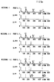
- Figure 1 shows the principle of the pulse-echo method.
- Figure 2 shows the formation of multiple echoes by reflection of the sound signal at the transducer or between the different ones Objects.
- Figure 3 shows features of a single echo.
- Figure 4 shows the principle of multiple echo evaluation.
- FIG. 5 shows the echo profile evaluation with changes over time Echo profile e.g. B. due to the agitator.
- FIG. 6 shows the echo profile evaluation by comparison with the learned echo profile (teach-in profile)
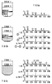
- Figure 7 shows the block diagram of a possible circuit arrangement for level measurement for echo detection as well as for the extraction of echo features.
- a microcontroller takes over control and evaluation of the measurements.
- the non-contact ultrasonic distance measurement is based on the determination of the transit time of a sound signal from a sound transducer to the test object and back (pulse-echo method).
- the principle is shown in Figure 1.
- the pulse-shaped transmission signal S is emitted periodically, reflected on the reflector (test object) and is present at the output of the US converter with a delay of time t e .
- t e Usually only the envelope signal HK of the high-frequency received signal is evaluated.
- the measuring range can range from a few mm to several 10 m. With ultrasound, a high path resolution in the direction of sound propagation can be achieved with comparatively little effort.
- a major advantage is the fact that it is largely insensitive to dust and lighting conditions as well as to the material properties, color and surface roughness of the test objects.
- the shape and amplitude of the echo signals can depend to a large extent on the orientation and the geometry of an object. This is caused by shadows, specular reflections and interference. They act as disturbance variables for distance measurement.
- Another problem is that in the case of well reflecting objects, multiple echoes often occur as a result of the reflection of the received signal at the transducer, which simulate the presence of further objects (see FIG. 2). This is always critical if the sensor does not only want to measure the shortest object distance.
- the transmission signal S which is emitted by the ultrasonic transducer USW, is first reflected on the object O a .
- E a represents the envelope curve HK of the first useful echo of the object O a .
- the second echo E a ' (first multiple echo) arrives at the ultrasonic transducer USW before the second useful echo E b' originating from the object b.
- E a '' is the second and E a ''' the third multiple echo of the object O a .
- E b ' is the first multiple echo of the object O b .
- E ab ' is the echo that arises due to the parasitic reflection path between the objects O a and O b .
- the task of signal processing is that of the product surface reliably separate incoming echo. Since the Envelopes of the individual echoes in the received signal are not necessarily show significant differences is one easy recognition based on the signal shape in practice hardly possible.
- the prior knowledge is always situation-specific. In the event of The level measurement applies that the product is the furthest assign a distant echo, which is not a multiple echo is. Knowledge can also serve as prior knowledge about the location of the fixed destinations in the container (e.g. in the form of a Teach-in echo profiles) as well as the maximum filling and Emptying speeds can be used. The consideration the history enables plausibility checks for Suppression of incorrect measurements and compensation of drift phenomena.
- Each multiple echo is characterized in that it is can be derived from one or more previous echoes. From these pre-echoes, which are themselves multiple echoes can, taking into account the spatial Divergence of the sound signal and the frequency-dependent Loss of propagation expected values for the characteristics of a Determine multiple echoes.
- the amplitude of a signal allows statements to be made about the losses that occur. It decreases at least with the factor 1 / r.
- r represents the distance to the US converter.
- attenuation ⁇ of approximately 0.015 dB / ⁇ . However, this decrease can be much larger and depends in particular on the reflection factors that occur.
- the signal shape of an echo can be determined by different parameters such as. B. rise and / or decay time or the ratio of amplitude to width can be characterized.
- a form factor F e derived from several signal shape parameters appears to be expedient.
- B a is the time that elapses between reaching the maximum amplitude A e and the 6dB drop to the left of it.
- B e is the time that elapses before the signal has decayed from the amplitude maximum A e to the 6 dB drop to the right of it.
- FIG. 4a illustrates the method using the example of two partial echoes (E a ′′ and E e ) on the basis of a measurement situation and the associated echo profile.
- a value that describes the multiple echo probability P MFE is assigned to each partial echo (FIG. 4b).
- the ordinate here carries the probability of a useful echo P neo , which is the complement to the multiple echo probability P MFE .
- kl means small difference, mt medium, gr large, n-gr negative large and p-gr positive large, s-gr very large, m-kl medium small and m-gr medium large difference, and s-gr very large difference .
- the level sensor presented here is subjected to a plausibility check using fuzzy rules.
- Each individual echo of the current measurement is compared with the echoes of the previous measurement cycle. There is a "good” match if both the transit time difference and the difference of the multiple echo probabilities P MFE are "small”.
- the absolute values for "small", “medium” and “large” transit time differences result, for example, from the maximum filling speed and measuring rate.
- the method is shown schematically in FIG.
- a basic problem with ultrasonic distance measurement at the same time to several objects is given by the fact that real Object echoes due to multiple or other interfering reflections can be covered.
- There is a level measurement the task is the sound signal reflected by the product to be detected reliably, the amplitude of which is very small compared to can be the fixed target echoes.
- the procedure also applies the principle of comparison between the fixed target echo profile saved in a learning phase (including agitators, which change periodically located in the detection area of the sensor) and the actual one Measurement operation recorded signal course. This Comparison is in the following in contrast to conventional Level sensors also using fuzzy rules carried out. Echoes with "good" agreement become fixed targets assigned and for further processing with less Weighting rated.
- an additional plausibility check of the measurement result is therefore carried out in addition to the fluctuation assessment described above.
- This uses the measured values with the highest useful echo probability (P NE max ) from the last n measurements and the currently displayed value as input variables.
- the display value is always updated when the new measured value lies within the tolerance zone specified by the maximum filling or emptying speed, a smooth averaging being carried out to smooth the display process.
- the display value is only overwritten when all measured values of the last n cycles lie within this tolerance zone and which is above a predetermined threshold for the echoes with the next higher useful echo probability. If the measured values are inadmissible, the last valid display value is retained. This state is also signaled by an error flag on the display.
- the plausibility check of the display value can also be carried out with the help of fuzzy controllers.
- the conception of the presented evaluation method allows the step-by-step testing of the individual modules. Based on The fuzzy sets can be used for test situations with multiple reflectors for the evaluation of multiple echoes, temporal fluctuations and consistency with the teach-in profile individually be created and optimized.
- Figure 7 shows the structure implemented for level measurement and a block diagram of the evaluation unit.
- the microcontroller MC generates a transmission pulse at predetermined time intervals, which is sent to the sound converter USW via the transmission output stage SE.
- the emitted sound signal After reflection from the objects O a , O b , O c, the emitted sound signal returns as an echo profile EP to the sound converter USW ..
- the demodulated echoes After passing through the preamplifier / envelope demodulator V, the demodulated echoes are obtained.
- a comparator delivers a corresponding output signal, the leading edge of which activates the peak detector for measuring the echo amplitude and an integrator for determining the width of the echo (form factor).
- the peak detector When the maximum echo amplitude is reached, the peak detector generates a control signal with which the content of the counter / memory module used for air time measurement is transferred to the buffer. With the trailing edge of the comparator signal, the individual features t e , A e , F e are transferred to the fuzzy evaluation for echo evaluation.
- the fuzzy evaluation takes over the multiple echo evaluation by assigning a multiple echo probability P -neo , the fluctuation evaluation by assigning a fluctuation probability P ne , the comparison with the learned echoes (teach-in) by assigning a probability P fill, and the plausibility check by assigning one Plausibility probability P meas .
- the multiple echo evaluation and the fluctuation evaluation are not only limited to the level measurement in their application. Where, on the other hand, the comparison with the learned and the plausibility check are level-specific.
- the complete received signal curve or the demodulated envelope curve sampled using an ADC module and cached.
- the feature extraction is then also carried out by appropriate Software.
- Evaluation methods can also be advantageous on non-contact measuring systems working on the spread electromagnetic waves are applied. These include, for example, pulse-radar arrangements for object location at greater distances or microwave sensors for distance measurement.
- the evaluation of the echo amplitudes can be due to the damping acting in the respective propagation medium can be optimally adapted through á priori knowledge.
Landscapes
- Physics & Mathematics (AREA)
- Engineering & Computer Science (AREA)
- Remote Sensing (AREA)
- Radar, Positioning & Navigation (AREA)
- General Physics & Mathematics (AREA)
- Acoustics & Sound (AREA)
- Thermal Sciences (AREA)
- Fluid Mechanics (AREA)
- Electromagnetism (AREA)
- Computer Networks & Wireless Communication (AREA)
- Measurement Of Velocity Or Position Using Acoustic Or Ultrasonic Waves (AREA)
- Investigating Or Analyzing Materials By The Use Of Ultrasonic Waves (AREA)
- Length Measuring Devices Characterised By Use Of Acoustic Means (AREA)
- Measurement Of Levels Of Liquids Or Fluent Solid Materials (AREA)
- Radar Systems Or Details Thereof (AREA)
Abstract
Description
Die Erfindung betrifft Ultraschall-Abstandssensoren auf der Basis des Impuls-Echo-Verfahrens mit erhöhter Meßsicherheit und verbesserter Unterdrückung von Störechosignalen. Bedeutende Applikationsgebiete sind die berührungslose Distanzmessung für die Positionierung von Werkstücken, der Kollisionsschutz oder die Füllstandsmeßtechnik.The invention relates to ultrasonic distance sensors on the Basis of the pulse-echo method with increased measurement certainty and improved suppression of false echo signals. Significant Application areas are non-contact distance measurement for the positioning of workpieces, collision protection or the level measurement technology.
Bekannt sind Ultraschall-Sensoren, welche den Abstand zwischen dem Sensor und einem schallreflektierenden Objekt durch die Messung der Laufzeit eines Schallsignals vom Sensor zum Objekt und zurück bestimmen. Hierbei wird das Echo üblicherweise dadurch erfaßt, daß das Überschreiten eines vorgegebenen Schwellwertes im Empfangssignal ausgewertet wird. Dieses Verfahren zur Abstandsmessung wertet üblicherweise die Laufzeit des ersten detektierten Echos aus. Eventuell folgende Echos von anderen im Erfassungsbereich des Sensors liegenden Objekten werden hingegen nicht weiterverarbeitet. Durch eine Zeitfenstersteuerung nach Mágori, V.; Walker, H.: Ultrasonic Presence Sensors with Wide Range and High Local Resolution. IEEE Trans. Ultrasonics, Ferroelectrics and Frequency Control, UFFC-34, No. 2, Mar. 1987, S. 202-211, kann dabei der zulässige Detektionsbereich für Echosignale in gewünschter Weise variiert werden. Auf diese Weise können auch Echos von Objekten mit unterschiedlichen Abständen zum Sensor erfaßt werden, indem das Auswertezeitfenster zyklisch über den Meßbereich verschoben wird, wobei die Auflösung der Einzelechos und die Gesamtmeßdauer mit geringerer Länge des Zeitfensters zunehmen.Ultrasonic sensors are known which measure the distance between the sensor and a sound reflecting object by measuring the transit time of a sound signal from the sensor determine to the object and back. This is the echo usually detected by exceeding a predetermined threshold value evaluated in the received signal becomes. This distance measurement method usually evaluates the transit time of the first detected echo. Perhaps following echoes from others within the detection range of the Objects lying on the sensor, however, are not further processed. Through a time window control according to Mágori, V .; Walker, H .: Ultrasonic Presence Sensors with Wide Range and High Local Resolution. IEEE Trans. Ultrasonics, Ferroelectrics and Frequency Control, UFFC-34, No. 2, Mar. 1987, pp. 202-211, the permissible detection range for echo signals can be varied in the desired manner. On this way you can also echo objects with different Distances to the sensor can be detected by the evaluation time window is cyclically shifted over the measuring range, where the resolution of the individual echoes and the total measuring time increase with a shorter length of the time window.
Bekannt sind außerdem Verfahren zur Verarbeitung von Ultraschall-Echosignalen,
bei denen das Empfangssignal digital
abgetastet und in einem Speicher abgelegt wird, wobei das
Empfangssignal auch die demodulierte Hüllkurve der Echos sein
kann (EP 0 459 336). Die Signalverarbeitung erfolgt im Anschluß
an die Aufzeichnung des Empfangssignals durch Extraktion
der Echos mittels eines geeigneten Verfahrens, z.B. Matched
Filter + Schwellwertdetektion. Auf diese Weise können
alle innerhalb einer Messung auftretenden Echos detektiert
werden.Methods for processing ultrasound echo signals are also known,
where the received signal is digital
is scanned and stored in a memory, the
Received signal can also be the demodulated envelope of the echoes
can (
Auch in dem Verfahren, das in Advances in Instrumentation and
Control, Vol 46, Teil 2, 1991, Research Triangle Park, NC,
US, Duncan: "Ultrasonics in Solids Level Measurements", Seiten
1355-1366 beschrieben wird, wird das ausgesendete und
später empfangene Ultraschallsignal mittels eines Mikroprozessors
digitalisiert und als Hüllkurve gespeichert. Das Verfahren
bezieht sich auf die Messung des Füllständs eines Behälters.
Zur Bestimmung des Nutzechos wird das Echoprofil des
Leerbehälters mit dem Echoprofil des gefüllten Behälters verglichen.
Weiterhin ist es möglich, das Nutzecho dadurch zu
erkennen, daß ein Vorwissen über die Beschaffenheit des in
dem Behälter befindlichen Füllguts und das dazu charakteristische
Echo zur Erkennung des Nutzechos verwendet wird.Also in the procedure described in Advances in Instrumentation and
Control, Vol 46,
Bekannt sind weiterhin Verfahren zur Unterdrückung von unerwünschten im Empfangssignal enthaltenen Echos, beispielsweise aufgrund störender Objekte, die sich zusätzlich zum Meßobjekt im Erfassungsbereich des Sensors befinden. Wenn die Störobjekte räumlich feststehen und gleichzeitig der Bewegungsbereich des Meßobjektes eingeschränkt ist, so kann eine hinreichende Unterdrückung von Störechos durch geeignete Wahl des Auswertezeitfensters erreicht werden.Methods for suppressing undesired ones are also known echoes contained in the received signal, for example due to disturbing objects that are in addition to the measurement object are in the detection range of the sensor. If the interfering objects be spatially fixed and at the same time the range of motion of the object to be measured is sufficient Suppression of false echoes by suitable selection of the Evaluation time window can be reached.
Weiterhin ist bekannt, daß Störobjektechos dadurch unterdrückt werden können, daß in einer Einlernphase, bei der sich das Meßobjekt nicht im Erfassungsbereich des Sensors befindet, zunächst alle Störobjektechos detektiert und in einem Speicher abgelegt werden (DE 33 37 690). Während des Meßbetriebes werden die aktuell detektierten Echos mit den eingelernten Echos verglichen. Bei einer hinreichenden Übereinstimmung wird das Echo als Störobjektecho klassifiziert und entsprechend unterdrückt, während die übrigen Echos Meßobjekten zugeordnet werden.It is also known that interference object echoes are suppressed as a result can be that in a learning phase in which the measurement object is not in the detection range of the sensor, initially all interference object echoes are detected and in one Storage can be stored (DE 33 37 690). During the measuring operation the currently detected echoes with the learned ones Compared echoes. With a sufficient match the echo is classified as an interference echo and correspondingly suppressed, while the other echoes measuring objects be assigned.
In den Schriften DE 33 37 690 und EP 0 459 336 werden Verfahren
beschrieben, welche durch Mehrfachreflexionen zwischen
dem Sensor und einem Objekt verursachte Störechos dadurch
ausblenden, daß die maximale auszuwertende Laufzeit begrenzt
wird, so daß außerhalb dieser Laufzeit auftretende Echos
ignoriert werden. Bei der in EP 0 459 336 dargestellten Lösung
kann zusätzlich auch die Echoamplitude als Kriterium für
die Mehrfachechounterdrückung ausgewertet werden. Für Meßsituationen
mit mehreren Objekten im Erfassungsbebereich
des Sensors sind diese Verfahren jedoch i.a. ungeeignet.Processes are described in the
Bekannt sind weiterhin Verfahren zur Unterdrückung von Störechos auf der Basis von Plausibilitätsprüfungen (DE 38 21 103 und DE 38 21 577). Da der Gradient, mit welchem sich die Meßsituation ändern kann, aufgrund der endlichen Bewegungsgeschwindigkeit von Objekten begrenzt ist, werden Echos nur dann ausgewertet, wenn ihre zeitliche Lage und Amplitude aufgrund vorheriger Meßsituationen hinreichend plausibel sind. Auf diese Weise können vor allem stochastisch auftretende Störsignale sicher unterdrückt werden.Methods for suppressing false echoes are also known on the basis of plausibility checks (DE 38 21 103 and DE 38 21 577). Since the gradient with which the measurement situation can change due to the finite speed of movement is limited by objects, echoes only then evaluated if based on their temporal position and amplitude previous measuring situations are sufficiently plausible. In this way, especially stochastically occurring ones Interference signals can be suppressed safely.
Allen obenbekannten Verfahren zur Auswertung von Echosignalen bei Ultraschall-Abstandssensoren ist gemeinsam, daß jedem im Empfangssignal detektierten Echo, welches kein stochastisches Störsignal ist, innerhalb der maximal auszuwertenden Laufzeit ein Objekt zugeordnet wird, wobei sich der Abstand zum Sensor aus der Schallaufzeit des Echos ergibt. Nachteilig an diesen bekannten Verfahren ist, daß somit auch Echos, welche beispielsweise durch mehrfache Reflexionen zwischen dem Sensor und einem einzigen Meßobjekt entstehen und die nicht außerhalb der maximalen auszuwertenden Laufzeit liegen, in fehlerhafter Weise weiteren, tatsächlich nicht vorhandenen Objekten zugeordnet werden. Dies kann zu sehr großen Fehlern bei der Beurteilung von Meßsituationen führen, insbesondere wenn sich Meßobjekte in geringem Abstand zum Sensor befinden.All methods known above for evaluating echo signals with ultrasonic distance sensors it is common that everyone in Received signal detected echo, which is not a stochastic Interference signal is within the maximum runtime to be evaluated an object is assigned, the distance to the sensor results from the sound propagation time of the echo. A disadvantage of this known method is that thus also echoes, for example due to multiple reflections between the sensor and a single measurement object and not outside of the maximum runtime to be evaluated are incorrect Wise further, actually non-existent objects be assigned. This can lead to very big mistakes in the Assessment of measurement situations, especially when The test objects are at a short distance from the sensor.
Zwischen dem Schallwandler und den Objekten, die im Erfassungsbereich des Sensors liegen, kann das Schallsignal mehrmals reflektiert werden. In Abhängigkeit vom Abstand zwischen dem Objekt und dem Sensor, der Objektreflektivität und der Geometrie des Schallwandlers sowie der Ausbreitungsdämpfung klingen diese Mehrfachechos mehr oder weniger schnell ab. Bei einer ebenen Wandler- bzw. Reflektoroberfläche sowie bei einem geringen Abstand zwischen dem Wandler und dem Objekt liegt die Abklingzeitkonstante der Mehrfachechos in der Größenordnung der einfachen Schallaufzeit. Diese ergibt sich aus dem Weg vom Sensor zum Objekt und zurück. Dadurch werden mehrere Echos desselben Objektes im Empfangssignal detektiert. Zusätzliche Störechos können auftreten, wenn sich mehrere Objekte im Erfassungsbereich des Sensors befinden. Ursache hierfür sind Reflexionswege zwischen den einzelnen Objekten bzw. Mehrfachreflexionen an verschiedenen Objekten.Between the transducer and the objects in the detection area of the sensor, the sound signal can occur several times be reflected. Depending on the distance between the object and the sensor, the object reflectivity and the Geometry of the transducer and the attenuation these multiple echoes subside more or less quickly. At a flat transducer or reflector surface as well with a small distance between the transducer and the object is the decay time constant of the multiple echoes in the magnitude of the simple sound propagation time. This results out of the way from the sensor to the object and back. Thereby multiple echoes of the same object in the received signal detected. Additional false echoes can occur if there are several objects in the detection range of the sensor. The reason for this are reflection paths between the individual Objects or multiple reflections on different Objects.
Bei allen bekannten Verfahren zur Echosignalverarbeitung besteht das Problem, daß die durch Mehrfachreflexionen entstehenden Störechos nicht von den direkten Objektechos unterschieden werden, was bei vielen in der Praxis vorkommenden Situationen zu Fehlmessungen führt.All known methods for processing echo signals exist the problem that those caused by multiple reflections False echoes do not differ from direct object echoes become what occurs in practice in many Situations leading to incorrect measurements.
Die Aufgabe der Erfindung ist es, ein Verfahren anzugeben, welches die beschriebenen Störechos eliminiert.The object of the invention is to provide a method which eliminates the false echoes described.
Gelöst wird die Aufgabe durch ein Verfahren gemäß dem Patentanspruch
1.The object is achieved by a method according to the
Vorteilhafte Weiterbildungen der Erfindung sind durch die in den Unteransprüchen angegebenen Merkmale gekennzeichnet.Advantageous further developments of the invention can be found in the features specified in the subclaims.
Die Erfindung ist vorteilhaft anwendbar für intelligente Abstandssensoren mit objektselektiven Meßeigenschaften, insbesondere für die Abstandmessung unter durch störende Objekte erschwerten Bedingungen.The invention can be advantageously used for intelligent distance sensors with object-selective measurement properties, in particular for the distance measurement under by interfering objects difficult conditions.
Im folgenden wird die Erfindung anhand von lediglich einen Ausführungsweg darstellenden Zeichnungen näher erläutert.In the following the invention is based on only one Execution path illustrating drawings explained in more detail.
Figur 1 zeigt das Prinzip des Puls-Echo-Verfahrens.Figure 1 shows the principle of the pulse-echo method.
Figur 2 zeigt die Entstehung von Mehrfachechos durch Reflexion des Schallsignals am Wandler oder zwischen den verschiedenen Objekten. Figure 2 shows the formation of multiple echoes by reflection of the sound signal at the transducer or between the different ones Objects.
Figur 3 zeigt Merkmale eines Einzelechos.Figure 3 shows features of a single echo.
Figur 4 zeigt das Prinzip der Mehrfachechoauswertung.Figure 4 shows the principle of multiple echo evaluation.
Figur 5 zeigt die Echoprofilauswertung bei sich zeitlich änderndem Echoprofil z. B. aufgrund des Rührwerkes.FIG. 5 shows the echo profile evaluation with changes over time Echo profile e.g. B. due to the agitator.
Figur 6 zeigt die Echoprofilauswertung durch Vergleich mit dem gelernten Echoprofil (Teach-in-Profil)FIG. 6 shows the echo profile evaluation by comparison with the learned echo profile (teach-in profile)
Figur 7 zeigt das Blockschaltbild einer möglichen Schaltungsanordnung für die Füllstandsmessung zur Echodetektion sowie zur Extraktion von Echomerkmalen. Ein Mikrocontroller übernimmt die Steuerung und die Auswertung der Messungen.Figure 7 shows the block diagram of a possible circuit arrangement for level measurement for echo detection as well as for the extraction of echo features. A microcontroller takes over control and evaluation of the measurements.
Die berührungslose Ultraschall-Abstandsmessung basiert auf der Bestimmung der Laufzeit eines Schallsignals von einem Schallwandler zum Meßobjekt und zurück (Impuls-Echo-Verfahren). Das Prinzip ist in Figur 1 dargestellt. Das impulsförmige Sendesignal S wird periodisch ausgesandt, am Reflektor (Meßobjekt) reflektiert und steht am Ausgang des US-Wandlers um die Zeit te verzögert an. Zumeist wird nur das Hüllkurvensignal HK des hochfrequenten Empfangssignal ausgewertet. Der Meßbereich kann je nach gewählter Schallfrequenz von einigen mm bis zu mehreren 10 m betragen. Mit Ultraschall ist bei vergleichsweise geringem Aufwand eine hohe Wegauflösung in Richtung der Schallausbreitung erreichbar. Ein wesentlicher Vorteil besteht in Gegensatz zum optischen System in der weitgehenden Unempflindlichkeit gegenüber Staub und Beleuchtungsverhaltnissen sowie gegenüber der Materialbeschaffenheit, Farbe und Oberflächenrauhigkeit der Meßobjekte. Die Form und Amplitude der Echosignale können in starkem Maße von der Orientierung sowie der Geometrie eines Objektes abhängen. Ursache hierfür sind Abschattungen, spiegelnde Reflexionen sowie Interferenzen. Für die Abstandsmessung wirken sie als Störgrößen. Ein weiteres Problem besteht darin, daß bei gut reflektierenden Objekten infolge der Reflexion des Empfangssignals am Wandler häufig Mehrfachechos auftreten, welche das Vorhandensein weiterer Objekte vortäuschen (siehe Figur 2). Dies ist immer dann kritisch, wenn vom Sensor nicht nur die kürzeste Objektdistanz gemessen werden soll.The non-contact ultrasonic distance measurement is based on the determination of the transit time of a sound signal from a sound transducer to the test object and back (pulse-echo method). The principle is shown in Figure 1. The pulse-shaped transmission signal S is emitted periodically, reflected on the reflector (test object) and is present at the output of the US converter with a delay of time t e . Usually only the envelope signal HK of the high-frequency received signal is evaluated. Depending on the selected sound frequency, the measuring range can range from a few mm to several 10 m. With ultrasound, a high path resolution in the direction of sound propagation can be achieved with comparatively little effort. In contrast to the optical system, a major advantage is the fact that it is largely insensitive to dust and lighting conditions as well as to the material properties, color and surface roughness of the test objects. The shape and amplitude of the echo signals can depend to a large extent on the orientation and the geometry of an object. This is caused by shadows, specular reflections and interference. They act as disturbance variables for distance measurement. Another problem is that in the case of well reflecting objects, multiple echoes often occur as a result of the reflection of the received signal at the transducer, which simulate the presence of further objects (see FIG. 2). This is always critical if the sensor does not only want to measure the shortest object distance.
Das Sendesignal S, das vom Ultraschallwandler USW ausgesandt wird, wird zuerst am Objekt Oa reflektiert. Ea stellt die Hüllkurve HK des ersten Nutzechos des Objekts Oa dar. Das zweite Echo Ea' (erstes Mehrfachecho) trifft vor dem zweiten Nutzecho Eb' das vom Objekt b stammt, am Ultraschallwandler USW ein. Ea'' ist das zweite und Ea''' das dritte Mehrfachecho des Objekts Oa. Eb' ist das erste Mehrfachecho des Objekts Ob. Eab' ist das Echo, das aufgrund des parasitären Reflexionswegs zwischen den Objekten Oa und Ob zustande kommt.The transmission signal S, which is emitted by the ultrasonic transducer USW, is first reflected on the object O a . E a represents the envelope curve HK of the first useful echo of the object O a . The second echo E a ' (first multiple echo) arrives at the ultrasonic transducer USW before the second useful echo E b' originating from the object b. E a '' is the second and E a ''' the third multiple echo of the object O a . E b ' is the first multiple echo of the object O b . E ab ' is the echo that arises due to the parasitic reflection path between the objects O a and O b .
Die Echos bzw. deren Hüllkurven sind mit folgenden Indizes
versehen und die Laufzeiten setzen sich wie folgt zusammen:
Bei der Füllstandsmessung wirken häufig mehrere Störgrößen gleichzeitig. Das an der Oberfläche von Schüttgütern rückgestreute Echo besitzt im allgemeinen eine wesentlich geringere Amplitude als von Verstrebungen oder anderen konstruktiven Elementen oberhalb des Schüttgutes hervorgerufene Reflexionen bzw. Mehrfachechos. Hinzu kommen zeitweise Abschattungen durch Rührwerke sowie Ablagerungen an den Behälterwänden, Weitere Störeinflüsse sind durch Luftturbulenzen und Störschall gegeben, welche Amplitudenfluktuationen von mehr als 20 dB bewirken können.Several disturbance variables often act in the level measurement at the same time. The backscattered on the surface of bulk goods Echo is generally much lower Amplitude as of struts or other constructive Reflections caused by elements above the bulk material or multiple echoes. There are also occasional shadows through agitators and deposits on the container walls, Further disturbances are caused by air turbulence and noise, which amplitude fluctuations of can cause more than 20 dB.
Aufgabe der Signalverabeitung ist es, das von der Füllgutoberfläche kommende Echo zuverlässig zu separieren. Da die Einhüllenden der einzelnen Echos im Empfangssignal nicht zwangsläufig signifikante Unterschiede aufweisen, ist eine einfache Erkennung anhand der Signalform in der Praxis kaum möglich.The task of signal processing is that of the product surface reliably separate incoming echo. Since the Envelopes of the individual echoes in the received signal are not necessarily show significant differences is one easy recognition based on the signal shape in practice hardly possible.
Die Separation von Nutz- und Störgrößen erfolgt deshalb mit einer Fuzzy Auswerteeinheit. Als Eingangsgrößen wirken hierbei:
- Merkmale zur Charakterisierung eines Einzelechos
- Merkmale zur Beschreibung der Relationen zwischen mehreren Einzelechos
- Historie
- á priori-Wissen
- Characteristics for characterizing a single echo
- Features to describe the relationships between several individual echoes
- history
- á priori knowledge
Das á priori-Wissen ist stets situationsspezifisch. Im Falle der Füllstandsmessung gilt, daß das Füllgut dem am weitesten entfernt liegenden Echo, welches kein Mehrfachecho ist, zuzuordnen ist. Als á priori- Wissen kann auch die Kenntnis über die Lage der Festziele im Behälter (z. B. in Form eines Teach-in-Echoprofiles) sowie über die maximalen Befüll- und Entleerungsgeschwindigkeiten genutzt werden. Die Berücksichtigung der Historie ermöglicht Plausibilitätsprüfungen zur Unterdrückung von Fehlmessungen und Kompensation von Drifterscheinungen.The prior knowledge is always situation-specific. In the event of The level measurement applies that the product is the furthest assign a distant echo, which is not a multiple echo is. Knowledge can also serve as prior knowledge about the location of the fixed destinations in the container (e.g. in the form of a Teach-in echo profiles) as well as the maximum filling and Emptying speeds can be used. The consideration the history enables plausibility checks for Suppression of incorrect measurements and compensation of drift phenomena.
Das Echoprofil einer einzelnen Messung muß anhand signifikanter Kriterien (Fig. 3) bewertet werden. Die durchgeführten Untersuchungen haben gezeigt, daß das jeweilige Echo hinreichend gut durch folgende Merkmale beschrieben werden kann:
- zeitliche Lagedes Maximums Laufzeit te
- Signalamplitude Ae des Maximums
- Formfaktor Fe (aus den 6dB Breiten des Maximums)
- temporal location of the maximum term t e
- Signal amplitude A e of the maximum
- Form factor F e (from the 6dB widths of the maximum)
Zur Vereinfachung des Auswerteaufwands genügt eine Aufzeichnung der Hüllkurve. Sämtliche Merkmale zur Beschreibung der Relationen zwischen jeweils zwei Echos untereinander sind daraus abgeleitete Größen.A recording is sufficient to simplify the evaluation effort the envelope. All features to describe the Relationships between two echoes are each other derived quantities.
Jedes Mehrfachecho ist dadurch gekennzeichnet, daß es sich aus einem oder mehreren vorhergehenden Echos ableiten läßt. Aus diesen Vorechos, welche auch selbst Mehrfachechos sein können, lassen sich unter Berücksichtigung der räumlichen Divergenz des Schallsignals sowie der frequenzabhängigen Ausbreitungsdämpfung Erwartungswerte für die Merkmale eines Mehrfachechos bestimmen.Each multiple echo is characterized in that it is can be derived from one or more previous echoes. From these pre-echoes, which are themselves multiple echoes can, taking into account the spatial Divergence of the sound signal and the frequency-dependent Loss of propagation expected values for the characteristics of a Determine multiple echoes.
Ein Nutzecho, das zur Zeit te auftritt, besitzt üblicherweise
ein Mehrfachecho 1. Ordnung zur Zeit 2te, ein Mehrfachecho
2. Ordnung zur Zeit 3te usw.. Für die erwartete Laufzeit
te eines Mehrfachechos an der Stelle k gilt also (siehe
hierzu auch Figur 2):
- i,j,k:
- Echoindex; ein höherer Index entspricht einer größeren Laufzeit
- i=j:
- erstes Mehrfachecho des Objektes an der Stelle i
- i, j, k:
- Echo index; a higher index corresponds to a longer term
- i = j:
- first multiple echo of the object at point i
Zusätzliche Mehrfachechos können durch Reflexionswege zwischen
mehreren Einzelobjekten hervorgerufen werden. Im einfachsten
Fall (dünne Platten als Reflektoren) gilt dann:
Die Amplitude eines Signals erlaubt Aussagen über die auftretenden
Verluste. Sie nimmt mindestens mit dem Faktor 1/r
ab. Dabei stellt r den Abstand zum US-Wandler dar. Hinzu
kommt noch eine Dämpfung α von etwa 0.015 dB/λ. Diese Abnahme
kann jedoch noch wesentlich größer sein und hängt insbesondere
von den auftretenden Reflexionsfaktoren ab. Hinsichtlich
der Amplitude Ae eines Mehrfachechos an der Stelle
k, vgl. Figur 2 Ea' Ea', Ea'', Ea''' welches sich aus den
Vorechos i und j zusammensetzt, muß somit aufgrund der Divergenz
des Schallstrahles (Ae ∼ 1/te) und der Ausbreitungsdämpfung
folgende Bedingung erfüllt sein, sofern keine
Reflexionswege zwischen den verschiedenen Objekten beitragen:
Für Mehrfachechos infolge eines Reflexionsweges zwischen
zwei Objekten i und j gilt zumindest:
Die Signalform eines Echos kann durch unterschiedliche Parameter
wie z. B. Anstiegs und/oder Abklingzeit oder das Verhaltnis
von Amplitude zu Breite charakterisiert werden. Für
die Praxis erscheint ein aus mehreren Signalformparametern
abgeleiteter Formfaktor Fe als zweckmäßig. Für das im Rahmen
dieser Erfindung entwickelte Auswerteverfahren wurde der
Formfaktor aus der Einhüllenden wie folgt bestimmt (siehe
Figur 3):
Wobei Ba die Zeit ist, die zwischen dem Erreichen des Amplitudenmaximums Ae und dem links davon liegenden 6dB Abfall verstreicht. Be ist die Zeit, die verstreicht, bis das Signal vom Amplitudenmaximum Ae bis zum rechts davon liegenden 6dB Abfall abgeklungen ist. Where B a is the time that elapses between reaching the maximum amplitude A e and the 6dB drop to the left of it. B e is the time that elapses before the signal has decayed from the amplitude maximum A e to the 6 dB drop to the right of it.
Bei Reflexionen an ebenen oder einfachen regelmäßig gekrümmten
Flächen bleibt die Signalform im wesentlichen erhalten.
In diesen Fällen besitzen Mehrfachechos eine ähnliche Einhüllende
wie die zugehörigen Vorechos i und j:
Das Verfahren zur Klassifizierung eines Echos als Nutz- oder
Mehrfachecho beruht darauf, daß die Merkmale jedes detektierten
Echos mit den aus den Vorechos berechneten Erwartungswerten
verglichen werden. Hierfür erweisen sich normierte
Merkmalsdifferenzen als besonders geeignet.
- Mmeß:
- gemessenes Merkmal m, wobei das Merkmal m te, Ae oder Fe sein kann.
- Merw:
- Erwartungswert des Merkmales m
- DM m:
- skalierte Merkmalsdifferenz
- M measure :
- measured characteristic m, where the characteristic may be mt e , A e or F e .
- M ext :
- Expected value of the characteristic m
- D M m :
- scaled feature difference
Im konkreten Fall bedeuten kleine Differenzen, daß das betreffende Echo mit höherer Wahrscheinlichkeit der Klasse "Mehrfachecho" zuzuordnen ist. Wegen der oben aufgeführten Einflußfaktoren auf die Schallausbreitung stellen die Erwartungswerte Merw stets nur Schätzwerte dar. Eine binäre Ja/Nein-Entscheidung bei der Mehrfachechobewertung ist somit kaum sinnvoll. Daher werden die Differenzwerte DM i als Eingangsgrößen für die Fuzzy-Auswerteeinheit verwendet. Figur 4a illustriert anhand einer Meßsituation und des zugehörigen Echoprofiles das Verfahren am Beispiel zweier Teilechos (Ea'' und Ee). Als Ergebnis der Defuzzifizierung wird jedem Teilecho ein Wert zugeordnet, welcher die Mehrfachecho-Wahrscheinlichkeit PMFE beschreibt (Figur 4b). Die Ordinate trägt hier die Wahrscheinlichkeit für ein Nutzecho Pneo, welche das Komplement zur Mehrfachechowahrscheinlichkeit PMFE ist. In Figur 4a bedeutet kl kleine Differenz, mt mittlere, gr große, n-gr negativ große und p-gr positiv große, s-gr sehr große, m-kl mittelkleine und m-gr mittelgroße Differenz, sowie s-gr sehr große Differenz.In the specific case, small differences mean that the echo in question is more likely to be assigned to the "multiple echo" class. Because of the above-listed factors influencing the sound propagation are the expected values M exp always estimates only. A binary yes / no decision in multiple echo evaluation is thus hardly meaningful. The difference values D M i are therefore used as input variables for the fuzzy evaluation unit. FIG. 4a illustrates the method using the example of two partial echoes (E a ″ and E e ) on the basis of a measurement situation and the associated echo profile. As a result of the defuzzification, a value that describes the multiple echo probability P MFE is assigned to each partial echo (FIG. 4b). The ordinate here carries the probability of a useful echo P neo , which is the complement to the multiple echo probability P MFE . In Figure 4a, kl means small difference, mt medium, gr large, n-gr negative large and p-gr positive large, s-gr very large, m-kl medium small and m-gr medium large difference, and s-gr very large difference .
Da die Bewegungsgeschwindigkeit von Objekten im Erfassungsbereich des Sensors stets begrenzt ist, kann sich das Echoprofil von einem zum anderen Meßzyklus nicht sprunghaft ändern. Dieses Wissen wird üblicherweise zur Plausibilitätsbewertung einzelner Echos genutzt. Da andererseits die Geschwindigkeit der Situationsänderung nur selten exakt bekannt ist und Echos aufgrund von Luftbewegungen oder zeitweisen Abschattungen stark fluktuieren können, erweisen sich Verfahren mit festen Schwellenwerten als nur bedingt geeignet.Because the speed of movement of objects in the detection area of the sensor is always limited, the echo profile can do not change abruptly from one measuring cycle to another. This knowledge usually becomes a plausibility assessment individual echoes used. On the other hand, because of the speed the change in situation is rarely known exactly and echoes due to air movement or intermittent Shadowing can fluctuate strongly, it turns out Procedures with fixed threshold values are only suitable to a limited extent.
Bei dem hier vorgestellten Füllstandssensor erfolgt eine Plausibilitätsprüfung mit Hilfe von Fuzzy-Regeln. Dabei wird jedes Einzelecho der aktuellen Messung mit den Echos des vorhergehenden Meßzyklusses verglichen. Eine "gute" Übereinstimmung liegt dann vor, wenn sowohl die Laufzeitdifferenz als auch die Differenz der Mehrfachecho-Wahrscheinlichkeiten PMFE "klein" sind. Die Absolutwerte für "kleine", "mittlere" und "große" Laufzeitdifferenzen ergeben sich beispielsweise aus maximaler Befüllgeschwindigkeit und Meßrate. Je nach Güte der Übereinstimmung mit einem Echo der vorhergehenden Messung wird der Wert für die Nutzecho-Wahrscheinlichkeit PNEo = 1 - PMFE der aktuellen Echos mit einem aus der Defuzzierung abgeleiteten Wichtungsfaktor multipliziert. Bei plötzlich verschwindenden Echos (z. B. Verdeckung durch Rührwerk) wird das aktuelle Profil durch das entsprechende Echo aus der vorhergehenden Messung mit verringerter Wichtung ergänzt. Damit enthält die jeweils letzte Messung das gewichtete akkumulierte Ergebnis aus mehreren vorhergehenden Meßzyklen. In Figur 5 ist das Verfahren schmatisch dargestellt.The level sensor presented here is subjected to a plausibility check using fuzzy rules. Each individual echo of the current measurement is compared with the echoes of the previous measurement cycle. There is a "good" match if both the transit time difference and the difference of the multiple echo probabilities P MFE are "small". The absolute values for "small", "medium" and "large" transit time differences result, for example, from the maximum filling speed and measuring rate. Depending on the quality of correspondence with an echo from the previous measurement, the value for the useful echo probability P NEo = 1 - P MFE of the current echoes is multiplied by a weighting factor derived from the defuzzification. If echoes suddenly disappear (e.g. masking by agitator), the current profile is supplemented by the corresponding echo from the previous measurement with reduced weighting. The last measurement in each case thus contains the weighted accumulated result from several previous measurement cycles. The method is shown schematically in FIG.
Ein Grundproblem bei der Ultraschall-Abstandsmessung gleichzeitig zu mehreren Objekten ist dadurch gegeben, daß echte Objektechos durch Mehrfach- oder andere Störreflexionen überdeckt werden können. Bei der Füllstandsmessung besteht die Aufgabe darin, das vom Füllgut reflektierte Schallsignal sicher zu detektieren, wobei dessen Amplitude sehr klein gegenüber den Festzielechos sein kann. Das erfindungsgemäße Verfahren wendet zusätzlich das Prinzip des Vergleichs zwischen dem in einer Einlernphase abgespeicherten Festziel-Echoprofil (einschließlich Rührwerke, welche sich periodisch im Erfassungsbereich des Sensors befinden) und dem im eigentlichen Meßbetrieb aufgenommenen Signalverlauf an. Dieser Vergleich wird im folgenden im Gegensatz zu herkömmlichen Füllstandssensoren ebenfalls mit Hilfe von Fuzzy-Regeln durchgeführt. Echos mit "guter" Übereinstimmung werden Festzielen zugeordnet und für die weitere Verarbeitung mit geringer Wichtung bewertet. Von den übrigen Echos wird das mit der größten Laufzeit, welches eine geringe MehrfachechoWahrscheinlichkeit besitzt, dem Füllgut zugeordnet. Für den Fall, daß alle detektierten Echos mit dem eingelernten Verlauf hinreichend gut übereinstimmen (z. B. wenn sich das Füllgut in Hohe eines Festzieles befindet), wird das letzte Echo mit hoher Nutzecho-Wahrscheinlichkeit ausgewertet. Die Bewertung der Abweichungen zwischen eingelerntem und gemessenem Echoprofil wird analog, wie vorher beschrieben, durchgeführt. Das Verfahren ist in Figur 6a-e illustriert. Vorteile der unscharfen Auswertung sind in der Kompensation von Driften und der damit möglichen adaptiven Nachführung des Teach-in-Verlaufes zu sehen.A basic problem with ultrasonic distance measurement at the same time to several objects is given by the fact that real Object echoes due to multiple or other interfering reflections can be covered. There is a level measurement the task is the sound signal reflected by the product to be detected reliably, the amplitude of which is very small compared to can be the fixed target echoes. The invention The procedure also applies the principle of comparison between the fixed target echo profile saved in a learning phase (including agitators, which change periodically located in the detection area of the sensor) and the actual one Measurement operation recorded signal course. This Comparison is in the following in contrast to conventional Level sensors also using fuzzy rules carried out. Echoes with "good" agreement become fixed targets assigned and for further processing with less Weighting rated. Of the other echoes, this is also the case the longest term, which has a low multiple echo probability owns, assigned to the product. For the Case that all detected echoes with the learned course agree sufficiently well (e.g. if that Product is at the height of a fixed destination), the last one Echo evaluated with a high useful echo probability. The Evaluation of the deviations between the learned and the measured Echo profile is carried out analogously, as previously described. The method is illustrated in Figure 6a-e. advantages the fuzzy evaluation are in the compensation of Drifting and the adaptive tracking of the To see the teach-in process.
Bei ungünstigen Reflexionsbedingungen an der Oberfläche eines Schüttgutes kann das eigentlich interessierende Füllstandsecho zeitweise bereits im Bereich der Rauschgrenze des Meßsystems liegen. In diesem Fall ist die Detektion des Nutzechos über mehrere Meßzyklen oft nur sporadisch möglich. Eine weitere Fehlerursache können Störechos bilden, welche durch parasitäre Reflexionswege zwischen dem Schüttgut und konstruktiven Elementen des Behälters entstehen, wie in Figur 6c gezeigt. Da diese Echos später als das Füllstandsecho am Schallempfänger eintreffen, können sie von der Auswertung fehlinterpretiert werden. With unfavorable reflection conditions on the surface of a Bulk goods can be the level echo that is actually of interest at times already in the area of the noise limit of the Measuring system lie. In this case the detection of the Useful echoes often only sporadically possible over several measuring cycles. Another cause of error can be false echoes, which due to parasitic reflection paths between the bulk material and constructive elements of the container arise, as in figure 6c shown. Because these echoes are later than the level echo Arrive at the sound receiver, they can from the evaluation be misinterpreted.
Zur Unterdrückung fehlerhafter Meßwertausgaben wird daher neben der im vorigen beschriebenen Fluktuationsbewertung eine zusätzliche Plausibilitätsprüfung des Meßergebnisses durchgeführt. Diese verwendet als Eingangsgrößen die Meßwerte mit der höchsten Nutzecho-Wahrscheinlichkeit (PNE max) aus den letzten n Messungen sowie dem aktuell angezeigten Wert. Der Anzeigewert wird immer dann aktualisiert, wenn der neue Meßwert innerhalb der durch die maximale Befüll- bzw. Entleergeschwindigkeit vorgegebenen Toleranzzone liegt, wobei zur Glättung des Anzeigeverlaufes eine gleitende Mittelwertbildung durchgeführt wird. Im anderen Fall wird der Anzeigewert erst dann überschrieben, wenn alle Meßwerte der letzten n Zyklen innerhalb dieser Toleranzzone liegen und der zu den Echos mit der nächst höheren Nutzecho-Wahrscheinlichkeit über einer vorgegebenen Schwelle liegt. Wenn die Meßwerte unzulässig streuen, bleibt der jeweils letzte gültige Anzeigewert erhalten. Dieser Zustand wird zugleich durch ein Fehlerflag über die Anzeige signalisiert. Die Plausibilitätsprüfung des Anzeigewertes kann ebenfalls mit Hilfe von Fuzzy-Reglern erfolgen.In order to suppress incorrect measured value outputs, an additional plausibility check of the measurement result is therefore carried out in addition to the fluctuation assessment described above. This uses the measured values with the highest useful echo probability (P NE max ) from the last n measurements and the currently displayed value as input variables. The display value is always updated when the new measured value lies within the tolerance zone specified by the maximum filling or emptying speed, a smooth averaging being carried out to smooth the display process. In the other case, the display value is only overwritten when all measured values of the last n cycles lie within this tolerance zone and which is above a predetermined threshold for the echoes with the next higher useful echo probability. If the measured values are inadmissible, the last valid display value is retained. This state is also signaled by an error flag on the display. The plausibility check of the display value can also be carried out with the help of fuzzy controllers.
Die Konzeption des vorgestellten Auswerteverfahrens erlaubt die schrittweise Erprobung der einzelnen Module. Anhand von Testsituationen mit mehreren Reflektoren können die Fuzzy-Sets für die Bewertung von Mehrfachechos, zeitlichen Fluktuationen und Übereinstimmung mit dem Teach-in-Profil einzeln erstellt und optimiert werden.The conception of the presented evaluation method allows the step-by-step testing of the individual modules. Based on The fuzzy sets can be used for test situations with multiple reflectors for the evaluation of multiple echoes, temporal fluctuations and consistency with the teach-in profile individually be created and optimized.
Bild 7 zeigt den für die Füllstandsmessung realisierten Aufbau und ein Blockschaltbild der Auswerteeinheit.Figure 7 shows the structure implemented for level measurement and a block diagram of the evaluation unit.
Durch den Mikrocontroller MC wird in vorgegebenen Zeitabständen ein Sendeimpuls generiert, welcher über die Sendeendstufe SE an den Schallwandler USW geführt wird. Das abgestrahlte Schallsignal gelangt nach der Reflexion an den Objekten Oa, Ob, Oc als Echoprofil EP zurück zum Schallwandler USW.. Nach Durchlaufen des Vorverstärkers/Hüllkurvendemodulators V erhält man die demodulierten Echos. Sobald im Empfangssignal ein vorgegebener Schwellwert überschritten wird, liefert ein Komparator ein entsprechendes Ausganssignal, dessen Vorderflanke den Peakdetektor zur Messung der Echoamplitude sowie einen Integrator zur Bestimmung der Breite des Echos (Formfaktor) aktiviert. Wenn die maximale Echoamplitude erreicht ist, generiert der Peakdetektor ein Steuersignal, mit welchem der Inhalt der zur Lufzeitmessung verwendeten Zähler-/Speicherbaugruppe in den Zwischenspeicher übernommen wird. Mit der Rückflanke des Komparatorsignals werden die einzelnen Merkmale te, Ae, Fe an die Fuzzyauswertung zur Echobewertung übergeben.The microcontroller MC generates a transmission pulse at predetermined time intervals, which is sent to the sound converter USW via the transmission output stage SE. After reflection from the objects O a , O b , O c, the emitted sound signal returns as an echo profile EP to the sound converter USW .. After passing through the preamplifier / envelope demodulator V, the demodulated echoes are obtained. As soon as a predetermined threshold value is exceeded in the received signal, a comparator delivers a corresponding output signal, the leading edge of which activates the peak detector for measuring the echo amplitude and an integrator for determining the width of the echo (form factor). When the maximum echo amplitude is reached, the peak detector generates a control signal with which the content of the counter / memory module used for air time measurement is transferred to the buffer. With the trailing edge of the comparator signal, the individual features t e , A e , F e are transferred to the fuzzy evaluation for echo evaluation.
Die Fuzzyauswertung übernimmt die Mehrfachechobewertung mit der Vergabe einer Mehrfachechowahrscheinlichkeit P-neo, die Fluktuationsbewertung mit der Vergabe einer Fluktuationswahrscheinlichkeit P ne, den Vergleich mit den eingelernten Echos (Teach-in) mit der Vergabe einer Wahrscheinlichkeit P fuell,und die Plausibilitätsüberprüfung mit der Vergabe einer Plausibilitätswahrscheinlichkeit P meß. Die Mehrfachechobewertung und die Fluktuationsbewertung beschränken sich in ihrer Anwendung nicht nur auf die Füllstandsmeßung. Wo hingegen der Vergleich mit Eingelerntem und die Plausibilitätsprüfung füllstandsmeßspezifisch sind.The fuzzy evaluation takes over the multiple echo evaluation by assigning a multiple echo probability P -neo , the fluctuation evaluation by assigning a fluctuation probability P ne , the comparison with the learned echoes (teach-in) by assigning a probability P fill, and the plausibility check by assigning one Plausibility probability P meas . The multiple echo evaluation and the fluctuation evaluation are not only limited to the level measurement in their application. Where, on the other hand, the comparison with the learned and the plausibility check are level-specific.
Alternativ kann der komplette Empfangssignalverlauf bzw. die demodulierte Hüllkurve mittels einer ADC-Baugruppe abgetastet und zwischengespeichert werden. Neben der Echobewertung erfolgt dann auch die Merkmalsextraktion durch entsprechende Software.Alternatively, the complete received signal curve or the demodulated envelope curve sampled using an ADC module and cached. In addition to the echo assessment the feature extraction is then also carried out by appropriate Software.
Die Untersuchungen zur Wichtung der Echomerkmale für die Mehrfachechoerkennung ergaben, daß die Laufzeit die größte Aussagekraft besitzt. Die Echoamplitude kann vor allem dann von Bedeutung sein, wenn Mehrfach- und Nutzecho zusammenfallen. Der Formfaktor besitzt das geringste Gewicht. Er trägt bei sich überlappenden Echos mit ähnlicher Amplitude zur verbesserten Bewertung von Mehrfachechos bei. The investigations on the weighting of the echo characteristics for the Multiple echo detection revealed that the runtime was the longest Is meaningful. Above all, the echo amplitude can then be of importance if multiple and useful echoes coincide. The form factor has the lowest weight. He wears with overlapping echoes with a similar amplitude improved evaluation of multiple echoes.
Gegenüber herkömmlichen Verfahren weist der beschriebene Fuzzy-Vergleich zwischen Teach-in-Echoprofil und Meßsignal wesentliche Vorteile auf, beispielsweise wenn vom Schüttgut selbst Mehrfachreflexionen erzeugt werden.Compared to conventional methods, the one described Fuzzy comparison between teach-in echo profile and measurement signal significant advantages, for example when bulk goods even multiple reflections are generated.
Das zunächst für Ultraschallsensoren beschriebene erfindungsgemäße Auswerteverfahren kann auch vorteilhaft auf berührungslos arbeitende Meßsysteme, welche auf der Ausbreitung elektromagnetischer Wellen beruhen, angewendet werden. Hierzu zählen beispielsweise Puls-Radar-Anordnungen zur Objektortung in größeren Entfernungen oder Mikrowellensensoren für die Abstandsmessung. Die Bewertung der Echoamplituden kann an die im jeweiligen Ausbreitungsmedium wirkende Dämpfung durch á priori Wissen optimal angepaßt werden.The invention described first for ultrasonic sensors Evaluation methods can also be advantageous on non-contact measuring systems working on the spread electromagnetic waves are applied. These include, for example, pulse-radar arrangements for object location at greater distances or microwave sensors for distance measurement. The evaluation of the echo amplitudes can be due to the damping acting in the respective propagation medium can be optimally adapted through á priori knowledge.
Claims (8)
- Process for the recognition and separation of useful and interfering echoes in the received signal of distance sensors, which operate in accordance with the pulse-echo principle,characterized by the following steps:1.1 in which the maxima in the received signal are detected and an echo is associated with each maximum,1.2 in which form factors which characterize the form of the echoes are formed and stored,1.3 in which the amplitudes and the instants of occurrence of the maxima are measured and stored,so that a set of echoes with low multiple echo probability is selected and the useful echo is determined therefrom with the aid of a priori knowledge or with knowledge of the measurement history.1.4 the differences between the measured amplitude values and expected values of the amplitudes which are obtained from the reciprocal signal transit times are determined,1.5 the differences between the measured instants of occurrence of the maxima and expected values of the instants of occurrence of the maxima which are obtained from the signal transit times are determined,1.6 the differences between the form factors determined in step 1.2 and expected values of the form factors which are obtained from the form factors of the preceding echoes are determined,1.7 the probability for a multiple echo is assumed to be the greater, the smaller are the differences which were determined in the steps 1.4, 1.5 and 1.6,1.8 the probability for an interfering echo is assumed to be the greater, the greater the probability for a multiple echo,
- Process according to Claim 1,
characterized in that2.1 a reference measurement is carried out without the object the distance of which from the distance sensor is of interest, and the received reference signal is stored,2.2 a measurement is carried out with the object the distance of which from the distance sensor is of interest, and the received measurement signal is stored,2.3 the echoes which in the reference signal are in concordance with the echoes in the measurement signal are allocated to fixed target echoes which represent interfering echoes. - Process according to Claim 1 or 2,
characterized in that to determine the form factor, the width of the echo and the width of the echo up to the maximum are set in ratio to one another. - Process according to Claim 1, 2 or 3,
characterized in that the probability for a multiple echo is determined by means of fuzzy logic. - Process according to one of Claims 1 to 4,
characterized in that the probability for an interfering echo is determined by means of fuzzy logic. - Process according to one of Claims 1 to 5,
characterized in that the expected value of the amplitude of a maximum is determined by means of the proportionality: - Process according to one of Claims 1 to 6,
characterized in that the expected value of the form factor for the echo to be evaluated is one of the form factors of the preceding echoes. - Use of the process according to one of Claims 1 to 7, characterized in that it is used for filling-level measurement.
Applications Claiming Priority (3)
| Application Number | Priority Date | Filing Date | Title |
|---|---|---|---|
| DE4308373A DE4308373C2 (en) | 1993-03-16 | 1993-03-16 | Process for the detection and separation of useful and false echoes in the received signal from distance sensors, which work according to the pulse-echo principle |
| DE4308373 | 1993-03-16 | ||
| PCT/DE1994/000249 WO1994022033A1 (en) | 1993-03-16 | 1994-03-10 | Process for recognizing and discriminating between useful and interfering echos in the reception signal of distance sensors working according to the pulse-echo principle |
Publications (2)
| Publication Number | Publication Date |
|---|---|
| EP0689679A1 EP0689679A1 (en) | 1996-01-03 |
| EP0689679B1 true EP0689679B1 (en) | 1998-05-27 |
Family
ID=6482964
Family Applications (1)
| Application Number | Title | Priority Date | Filing Date |
|---|---|---|---|
| EP94908958A Expired - Lifetime EP0689679B1 (en) | 1993-03-16 | 1994-03-10 | Process for recognizing and discriminating between useful and interfering echos in the reception signal of distance sensors working according to the pulse-echo principle |
Country Status (8)
| Country | Link |
|---|---|
| US (1) | US5587969A (en) |
| EP (1) | EP0689679B1 (en) |
| JP (1) | JP3207426B2 (en) |
| AT (1) | ATE166726T1 (en) |
| DE (2) | DE4308373C2 (en) |
| DK (1) | DK0689679T3 (en) |
| ES (1) | ES2117258T3 (en) |
| WO (1) | WO1994022033A1 (en) |
Cited By (3)
| Publication number | Priority date | Publication date | Assignee | Title |
|---|---|---|---|---|
| DE10249544A1 (en) * | 2002-10-23 | 2004-05-06 | Endress + Hauser Gmbh + Co. Kg | Level measurement using transition time principle involves forming echo function asymmetry factor, deriving transition time to surface and back and correcting for asymmetry |
| EP1628119A2 (en) | 2004-08-16 | 2006-02-22 | VEGA Grieshaber KG | Radar level measurement device with automatic echo signal determination |
| CN106909077A (en) * | 2017-03-16 | 2017-06-30 | 深圳市正弦电气股份有限公司 | A kind of control method of frequency converter S curve acceleration and deceleration mutation |
Families Citing this family (82)
| Publication number | Priority date | Publication date | Assignee | Title |
|---|---|---|---|---|
| DE4406525C2 (en) * | 1994-02-28 | 1996-10-24 | Siemens Ag | Method for determining the position of an object relative to the background using ultrasound |
| GB9502087D0 (en) * | 1995-02-02 | 1995-03-22 | Croma Dev Ltd | Improvements relating to pulse echo distance measurement |
| DE19540170C2 (en) * | 1995-10-27 | 1998-01-29 | Endress Hauser Gmbh Co | Method and arrangement for suppressing fixed target echoes during distance measurement according to the pulse transit time principle |
| DE19533303C2 (en) * | 1995-09-08 | 1997-08-14 | Siemens Ag | Device and method for detecting inhomogeneities in the cooling circuit of a transformer |
| US6118282A (en) * | 1995-12-19 | 2000-09-12 | Endress & Hauser Gmbh & Co. | Sensor apparatus |
| US5661251A (en) * | 1995-12-19 | 1997-08-26 | Endress + Hauser Gmbh + Co. | Sensor apparatus for process measurement |
| US5827985A (en) * | 1995-12-19 | 1998-10-27 | Endress + Hauser Gmbh + Co. | Sensor apparatus for process measurement |
| US5884231A (en) * | 1995-12-21 | 1999-03-16 | Endress & Hauser Gmbh & Co. | Processor apparatus and method for a process measurement signal |
| US5841666A (en) * | 1995-12-21 | 1998-11-24 | Endress + Hauser Gmbh + Co. | Processor apparatus and method for a process measurement signal |
| GB9606151D0 (en) * | 1996-03-23 | 1996-05-29 | Smiths Industries Plc | Fluid-gauging systems and probes |
| US5768939A (en) * | 1996-06-10 | 1998-06-23 | Kistler-Morse Corporation | Method and apparatus for acoustic level measurements |
| US5793704A (en) * | 1996-12-13 | 1998-08-11 | Solid Scientific Research And Development Ltd. | Method and device for ultrasonic ranging |
| DE19717399C2 (en) * | 1997-04-24 | 2001-05-23 | Martin Spies | Device for determining the distance and type of objects and the visibility |
| DE29709926U1 (en) * | 1997-06-08 | 1997-08-21 | Sailer Josef | Level detection system |
| US6078280A (en) * | 1998-01-09 | 2000-06-20 | Endress + Hauser Gmbh + Co. | Periodic probe mapping |
| US5973637A (en) * | 1998-01-09 | 1999-10-26 | Endress + Hauser Gmbh + Co. | Partial probe mapping |
| DE19805515A1 (en) * | 1998-02-11 | 1999-08-12 | Bayerische Motoren Werke Ag | Obstacle detection system in a motor vehicle |
| DE19824267A1 (en) * | 1998-05-29 | 1999-12-02 | Siemens Ag | Useful echo and clutter determination method for distance sensor, e.g. level detector |
| US6166681A (en) * | 1998-08-18 | 2000-12-26 | Usx Corporation | Measuring the thickness of materials |
| US6152238A (en) * | 1998-09-23 | 2000-11-28 | Laser Alignment, Inc. | Control and method for positioning a tool of a construction apparatus |
| US6559657B1 (en) | 1999-01-13 | 2003-05-06 | Endress+Hauser Gmbh+Co. | Probe mapping diagnostic methods |
| US6271762B1 (en) | 1999-02-27 | 2001-08-07 | Breed Automotive Technology, Inc. | Occupant position system and method using ultrasonic technology |
| DE50014809D1 (en) * | 1999-03-24 | 2008-01-10 | Siemens Ag | Method for level measurement |
| DE10024353A1 (en) | 2000-05-17 | 2001-12-13 | Endress Hauser Gmbh Co | Method and device for determining the fill level of a medium in a container |
| US6460412B1 (en) | 2000-10-27 | 2002-10-08 | Union Carbide Chemicals & Plastics Technology Corporation | Detection of dynamic fluidized bed level in a fluidized bed polymerization reactor using ultrasonic waves or microwaves |
| DE10133081A1 (en) * | 2001-07-11 | 2003-01-30 | Grieshaber Vega Kg | Level measurement method and level measuring device |
| CA2454748C (en) * | 2001-07-27 | 2011-10-25 | Endress + Hauser Gmbh + Co.Kg | Method for evaluating the measurement signals of a propagation-time based measurement device |
| DE10139242A1 (en) * | 2001-08-09 | 2003-03-06 | Grieshaber Vega Kg | Method and device for detecting a filling process |
| US6556511B1 (en) | 2001-11-01 | 2003-04-29 | Techno Research | Method of locking onto and tracking a target |
| US6545946B1 (en) * | 2002-02-14 | 2003-04-08 | Rosemount Aerospace Inc. | Method and apparatus for eliminating substantially false echoes produced by electrical noise induced into high gain receiver circuits |
| US6954685B2 (en) * | 2002-04-23 | 2005-10-11 | Lord Corporation | Aircraft vehicular propulsion system monitoring device and method |
| US7925392B2 (en) | 2002-04-23 | 2011-04-12 | Lord Corporation | Aircraft vehicular propulsion system monitoring device and method |
| WO2004010093A1 (en) * | 2002-07-19 | 2004-01-29 | Vega Grieshaber Kg | Method and device for determining an expectancy range for a level echo and a spurious echo |
| DE10305003A1 (en) * | 2003-02-07 | 2004-08-19 | Jäger, Frank-Michael | Liquid detection unit, comprises an ultrasound transducer located on a container wall, with a piezo electric element that produces an ultrasound impulse |
| DE10309861B4 (en) * | 2003-03-06 | 2006-05-04 | Robert Seuffer Gmbh & Co. Kg | Method and device for determining at least one chemical or physical property of a liquid in level measurement in a container |
| DE10314557A1 (en) * | 2003-03-31 | 2004-10-28 | Siemens Ag | Compact microwave proximity sensor with low power consumption thanks to power measurement on a stimulated local oscillator |
| US6935177B2 (en) * | 2003-09-29 | 2005-08-30 | Siemens Milltronics Process Instruments Inc. | Method for an entropy filter echo processing in time-of-flight or level measurement systems |
| DE10360710A1 (en) * | 2003-12-19 | 2005-10-06 | Endress + Hauser Gmbh + Co. Kg | Method for level measurement according to the transit time principle |
| US6972712B1 (en) | 2004-06-24 | 2005-12-06 | Saab Rosemount Tank Rader Ab | Near zone detection in radar level gauge system |
| DE102004052110B4 (en) | 2004-10-26 | 2018-08-23 | Endress+Hauser SE+Co. KG | Method for level measurement according to the transit time principle |
| DE102004059964A1 (en) | 2004-12-13 | 2006-06-14 | Truma Gerätetechnik GmbH & Co. KG | Ultrasonic measuring device for a container |
| DE102005003152A1 (en) * | 2005-01-21 | 2006-07-27 | Endress + Hauser Gmbh + Co. Kg | Procedure for checking the proper functioning of a level gauge |
| US7355548B2 (en) | 2005-09-01 | 2008-04-08 | Rosemount Tank Radar Ab | Processing of tank signal in radar level gauge system |
| US7819144B2 (en) * | 2005-09-01 | 2010-10-26 | Wotring Blake R | Method and apparatus for loading and conditioning materials |
| DE102005063079B4 (en) * | 2005-12-29 | 2018-09-20 | Endress+Hauser SE+Co. KG | Method for detecting and monitoring the level of a medium in a container |
| US7266042B1 (en) | 2006-03-31 | 2007-09-04 | The United States Of America As Represented By The Secretary Of The Navy | Multi-stage maximum likelihood target estimator |
| US20080060431A1 (en) * | 2006-09-07 | 2008-03-13 | Christer Frovik | Radar level gauging |
| DE102007062782B4 (en) * | 2006-12-27 | 2016-02-25 | SONOTEC Dr. zur Horst-Meyer & Münch oHG | Piston or pig detection device and piston or pig detection method |
| WO2008147223A1 (en) * | 2007-05-28 | 2008-12-04 | Bep Marine Limited | Improvements relating to ultrasonic distance measuring devices |
| DE102007060579B4 (en) | 2007-12-13 | 2019-04-25 | Endress+Hauser SE+Co. KG | Method for determining and / or assessing the filling state of a container filled with at least one medium |
| EP2309235A1 (en) * | 2009-10-12 | 2011-04-13 | VEGA Grieshaber KG | Segment-based signal processing |
| DE102009055262A1 (en) * | 2009-12-23 | 2011-06-30 | Endress + Hauser GmbH + Co. KG, 79689 | Method for determining and monitoring the level of a medium in a container according to a transit time measurement method |
| EP2372318B1 (en) * | 2010-03-26 | 2020-03-18 | VEGA Grieshaber KG | Noise echo storage for container noises |
| EP2418465B1 (en) * | 2010-07-19 | 2017-02-22 | VEGA Grieshaber KG | Amplitude profiling in fill level measuring devices |
| EP2423707B1 (en) * | 2010-08-25 | 2013-04-17 | Siemens Aktiengesellschaft | A method for determining the echo distance in an acoustic pulse-echo ranging system |
| DE102010042525A1 (en) | 2010-10-15 | 2012-04-19 | Endress + Hauser Gmbh + Co. Kg | Method for determining and monitoring the level of a medium in a container by means of a level gauge according to a transit time measurement method |
| CN105181007A (en) * | 2010-11-11 | 2015-12-23 | Ssi技术公司 | System and method of determining a quality and a quantity of a fluid of tank with a base |
| EP2527801B1 (en) | 2011-05-27 | 2019-12-11 | VEGA Grieshaber KG | Method and device for determining media and container characteristics |
| EP2527802B1 (en) | 2011-05-27 | 2019-12-18 | VEGA Grieshaber KG | Method and device for determining media and container characteristics |
| EP2584324B1 (en) * | 2011-10-17 | 2018-09-19 | VEGA Grieshaber KG | Fill level measuring device and method for determining a functional correlation between different tracks |
| DE102012101725A1 (en) * | 2012-03-01 | 2013-09-05 | Sick Ag | Method for level measurement |
| DE102012007979A1 (en) * | 2012-04-24 | 2013-10-24 | Krohne Messtechnik Gmbh | Method for determining the level of a medium and corresponding device |
| DE102012207724A1 (en) * | 2012-05-09 | 2013-11-14 | Continental Automotive Gmbh | Method for measuring the level of a liquid |
| DE102012104858A1 (en) * | 2012-06-05 | 2013-12-05 | Endress + Hauser Gmbh + Co. Kg | Method for level measurement according to the transit time principle |
| US20150164467A1 (en) * | 2012-07-18 | 2015-06-18 | Furono Electric Co., Ltd. | Waveform tracking device, ultrasound diagnostic device, and waveform tracking method |
| US9587939B2 (en) * | 2013-01-23 | 2017-03-07 | Apm Automation Solutions Ltd. | Method and system for measuring content of a bin |
| US9518860B2 (en) * | 2013-01-31 | 2016-12-13 | Apm Automation Solutions Ltd | System and method for fuzzy logic based measurement of a content of a bin |
| DE102013108436B4 (en) * | 2013-08-05 | 2022-10-13 | Finetek Co., Ltd. | Frequency modulated continuous wave radar level device and method of measurement therefor |
| DE102013109606B4 (en) | 2013-09-03 | 2022-05-12 | Pepperl + Fuchs Gmbh | Method and device for detecting a filling level in a collection container |
| CN106164626A (en) * | 2014-06-03 | 2016-11-23 | Vega格里沙贝两合公司 | Container profile and the identification of defect profile |
| CN105300468B (en) * | 2014-07-22 | 2020-09-18 | 罗斯蒙特储罐雷达股份公司 | System and method for measuring contents of a bin based on fuzzy logic |
| EP3098577A1 (en) * | 2015-05-29 | 2016-11-30 | Shell Internationale Research Maatschappij B.V. | Fuel level detection system and method |
| ES2738328T3 (en) * | 2015-09-29 | 2020-01-22 | Handtmann Albert Maschf | Filling machine and procedure for filling level measurement with radar sensor, in particular in sausage production |
| DE102016100674B4 (en) * | 2016-01-15 | 2019-03-21 | Krohne Messtechnik Gmbh | Method for operating a non-contact ultrasonic or radar level gauge and non-contact ultrasonic or radar level gauge |
| CN109254292B (en) * | 2017-07-13 | 2021-06-15 | 广州极飞科技股份有限公司 | Sonar ranging method and device and execution equipment |
| JP7081143B2 (en) * | 2017-12-27 | 2022-06-07 | セイコーエプソン株式会社 | Ultrasonic device and ultrasonic measurement method |
| JP7245070B2 (en) * | 2019-02-19 | 2023-03-23 | 積水マテリアルソリューションズ株式会社 | Information processing device, program, trash container |
| RU2719210C1 (en) * | 2019-05-06 | 2020-04-17 | Акционерное Общество "Концерн "Океанприбор" | Echo sounder |
| JP7218683B2 (en) * | 2019-07-10 | 2023-02-07 | 株式会社デンソー | Ultrasonic distance measuring device |
| WO2021152482A1 (en) | 2020-01-27 | 2021-08-05 | Mts Sensor Technologie Gmbh & Co. Kg | Magnetostrictive position measurement using frequency domain analysis |
| EP4102194B1 (en) * | 2021-06-07 | 2023-07-26 | VEGA Grieshaber KG | Fill level radar with variable quantization accuracy |
| CN113917397A (en) * | 2021-09-17 | 2022-01-11 | 深圳市睿联技术股份有限公司 | Ranging method, ranging device, ranging system and computer-readable storage medium |
Family Cites Families (10)
| Publication number | Priority date | Publication date | Assignee | Title |
|---|---|---|---|---|
| US4380807A (en) * | 1979-10-03 | 1983-04-19 | Polaroid Corporation | Echo recognition system |
| DE3337690A1 (en) * | 1983-10-17 | 1985-04-25 | VEGA Grieshaber GmbH & Co, 7620 Wolfach | Method and device for measuring the filling level in a container by means of sound/ultrasonic waves |
| US4992998A (en) * | 1986-10-03 | 1991-02-12 | Federal Industries Industrial Group Inc. | Acoustic range finding system |
| US4890266A (en) * | 1987-04-22 | 1989-12-26 | Federal Industries Industrial Group Inc. | Acoustic range finding system |
| US4821569A (en) * | 1987-10-30 | 1989-04-18 | Fischer & Porter Co. | Parasitic echo pulse rejector for ultrasonic liquid level meter |
| DE3812293A1 (en) * | 1988-04-13 | 1989-10-26 | Endress Hauser Gmbh Co | LEVEL MEASURING DEVICE |
| EP0346687B1 (en) * | 1988-06-13 | 1993-08-04 | Siemens Aktiengesellschaft | Method of suppressing interference in ultrasonic distance measurement |
| DE3821577A1 (en) * | 1988-06-25 | 1990-01-04 | Hipp Johann F | Method and device for obstruction identification using ultrasound range measurement |
| US5060205A (en) * | 1990-05-29 | 1991-10-22 | Deere & Company | Ultrasonic distance measuring system |
| US5157639A (en) * | 1990-09-04 | 1992-10-20 | Magnetrol International | Ultrasonic detector |
-
1993
- 1993-03-16 DE DE4308373A patent/DE4308373C2/en not_active Expired - Fee Related
-
1994
- 1994-03-10 AT AT94908958T patent/ATE166726T1/en not_active IP Right Cessation
- 1994-03-10 US US08/522,310 patent/US5587969A/en not_active Expired - Lifetime
- 1994-03-10 JP JP52050694A patent/JP3207426B2/en not_active Expired - Fee Related
- 1994-03-10 DE DE59406091T patent/DE59406091D1/en not_active Expired - Lifetime
- 1994-03-10 DK DK94908958T patent/DK0689679T3/en active
- 1994-03-10 WO PCT/DE1994/000249 patent/WO1994022033A1/en active IP Right Grant
- 1994-03-10 EP EP94908958A patent/EP0689679B1/en not_active Expired - Lifetime
- 1994-03-10 ES ES94908958T patent/ES2117258T3/en not_active Expired - Lifetime
Cited By (5)
| Publication number | Priority date | Publication date | Assignee | Title |
|---|---|---|---|---|
| DE10249544A1 (en) * | 2002-10-23 | 2004-05-06 | Endress + Hauser Gmbh + Co. Kg | Level measurement using transition time principle involves forming echo function asymmetry factor, deriving transition time to surface and back and correcting for asymmetry |
| DE10249544B4 (en) * | 2002-10-23 | 2012-05-31 | Endress + Hauser Gmbh + Co. Kg | Method for level measurement according to the transit time principle |
| EP1628119A2 (en) | 2004-08-16 | 2006-02-22 | VEGA Grieshaber KG | Radar level measurement device with automatic echo signal determination |
| CN106909077A (en) * | 2017-03-16 | 2017-06-30 | 深圳市正弦电气股份有限公司 | A kind of control method of frequency converter S curve acceleration and deceleration mutation |
| CN106909077B (en) * | 2017-03-16 | 2020-05-05 | 深圳市正弦电气股份有限公司 | Control method for S curve acceleration and deceleration mutation of frequency converter |
Also Published As
| Publication number | Publication date |
|---|---|
| DE59406091D1 (en) | 1998-07-02 |
| ES2117258T3 (en) | 1998-08-01 |
| JPH08507607A (en) | 1996-08-13 |
| JP3207426B2 (en) | 2001-09-10 |
| DE4308373C2 (en) | 1995-04-13 |
| DK0689679T3 (en) | 1999-03-22 |
| DE4308373A1 (en) | 1994-09-22 |
| ATE166726T1 (en) | 1998-06-15 |
| EP0689679A1 (en) | 1996-01-03 |
| WO1994022033A1 (en) | 1994-09-29 |
| US5587969A (en) | 1996-12-24 |
Similar Documents
| Publication | Publication Date | Title |
|---|---|---|
| EP0689679B1 (en) | Process for recognizing and discriminating between useful and interfering echos in the reception signal of distance sensors working according to the pulse-echo principle | |
| EP2418465B1 (en) | Amplitude profiling in fill level measuring devices | |
| EP1523661B1 (en) | Method and device for determining an expectancy range for a level echo and a spurious echo | |
| EP2527801B1 (en) | Method and device for determining media and container characteristics | |
| EP2527805B1 (en) | Evaluation device and method for determining a parameter for the position of a boundary area in a container | |
| DE102006062606A1 (en) | Medium filling level determining and monitoring method for e.g. freely radiating microwave measuring device, involves adjusting shielding curve, evaluation curve and/or echo parameter based on change of position and/or amplitude of signals | |
| EP2516973A2 (en) | Method for determining and monitoring the level of a medium in a container according to a runtime measurement method | |
| EP3025128B1 (en) | Method for determining and monitoring the level of a medium in a container according to a transit time measurement method | |
| DE102010033207A1 (en) | Method and device for environmental monitoring for a vehicle | |
| EP2372319A1 (en) | Noise echo storage for container noises | |
| WO2007077079A1 (en) | Method for determining and monitoring the level of a medium in a container by propagation time measurement | |
| DE4327333A1 (en) | Method for measuring the filling level of a liquid in a container, using the radar principle | |
| DE102013114737A1 (en) | Laser-based level measuring device | |
| DE102018200688A1 (en) | Method and device for operating an acoustic sensor | |
| DE102009054664A1 (en) | Method and device for active detection of objects taking into account previous detection results | |
| DE102012213580A1 (en) | Method and device for evaluating a received alternating signal | |
| EP3258296B1 (en) | Reflection microwave barrier | |
| EP1039273B1 (en) | Fluid level measurement method | |
| WO1999038029A1 (en) | Surveillance device for signal-echo sensors | |
| EP1358450B1 (en) | Method and device for rough discrimination between the liquid or bulk material state of a filling material in a container | |
| DE102014219399A1 (en) | Ultrasonic measuring system, ultrasonic sensor and method for investigating an ultrasonic echo | |
| EP1283412A2 (en) | Method and apparatus for detecting a filling process | |
| DE10238896B4 (en) | Method for evaluating radar data | |
| DE102022004971B3 (en) | Ultrasonic sensor with an object detection of objects in the close range | |
| DE102022004967B3 (en) | Method for detecting objects in the close range of an ultrasonic sensor |
Legal Events
| Date | Code | Title | Description |
|---|---|---|---|
| PUAI | Public reference made under article 153(3) epc to a published international application that has entered the european phase |
Free format text: ORIGINAL CODE: 0009012 |
|
| 17P | Request for examination filed |
Effective date: 19950904 |
|
| AK | Designated contracting states |
Kind code of ref document: A1 Designated state(s): AT BE CH DE DK ES FR GB IT LI LU NL SE |
|
| 17Q | First examination report despatched |
Effective date: 19960604 |
|
| GRAG | Despatch of communication of intention to grant |
Free format text: ORIGINAL CODE: EPIDOS AGRA |
|
| GRAG | Despatch of communication of intention to grant |
Free format text: ORIGINAL CODE: EPIDOS AGRA |
|
| GRAH | Despatch of communication of intention to grant a patent |
Free format text: ORIGINAL CODE: EPIDOS IGRA |
|
| GRAH | Despatch of communication of intention to grant a patent |
Free format text: ORIGINAL CODE: EPIDOS IGRA |
|
| GRAA | (expected) grant |
Free format text: ORIGINAL CODE: 0009210 |
|
| AK | Designated contracting states |
Kind code of ref document: B1 Designated state(s): AT BE CH DE DK ES FR GB IT LI LU NL SE |
|
| REF | Corresponds to: |
Ref document number: 166726 Country of ref document: AT Date of ref document: 19980615 Kind code of ref document: T |
|
| REG | Reference to a national code |
Ref country code: CH Ref legal event code: NV Representative=s name: SIEMENS SCHWEIZ AG Ref country code: CH Ref legal event code: EP |
|
| REF | Corresponds to: |
Ref document number: 59406091 Country of ref document: DE Date of ref document: 19980702 |
|
| ET | Fr: translation filed | ||
| REG | Reference to a national code |
Ref country code: ES Ref legal event code: FG2A Ref document number: 2117258 Country of ref document: ES Kind code of ref document: T3 |
|
| ITF | It: translation for a ep patent filed |
Owner name: STUDIO JAUMANN P. & C. S.N.C. |
|
| GBT | Gb: translation of ep patent filed (gb section 77(6)(a)/1977) |
Effective date: 19980729 |
|
| PGFP | Annual fee paid to national office [announced via postgrant information from national office to epo] |
Ref country code: AT Payment date: 19990303 Year of fee payment: 6 |
|
| PGFP | Annual fee paid to national office [announced via postgrant information from national office to epo] |
Ref country code: DK Payment date: 19990309 Year of fee payment: 6 |
|
| PGFP | Annual fee paid to national office [announced via postgrant information from national office to epo] |
Ref country code: LU Payment date: 19990310 Year of fee payment: 6 |
|
| PGFP | Annual fee paid to national office [announced via postgrant information from national office to epo] |
Ref country code: BE Payment date: 19990312 Year of fee payment: 6 |
|
| REG | Reference to a national code |
Ref country code: DK Ref legal event code: T3 |
|
| PGFP | Annual fee paid to national office [announced via postgrant information from national office to epo] |
Ref country code: ES Payment date: 19990325 Year of fee payment: 6 |
|
| PLBE | No opposition filed within time limit |
Free format text: ORIGINAL CODE: 0009261 |
|
| STAA | Information on the status of an ep patent application or granted ep patent |
Free format text: STATUS: NO OPPOSITION FILED WITHIN TIME LIMIT |
|
| 26N | No opposition filed | ||
| PG25 | Lapsed in a contracting state [announced via postgrant information from national office to epo] |
Ref country code: LU Free format text: LAPSE BECAUSE OF NON-PAYMENT OF DUE FEES Effective date: 20000310 Ref country code: DK Free format text: LAPSE BECAUSE OF NON-PAYMENT OF DUE FEES Effective date: 20000310 Ref country code: AT Free format text: LAPSE BECAUSE OF NON-PAYMENT OF DUE FEES Effective date: 20000310 |
|
| PG25 | Lapsed in a contracting state [announced via postgrant information from national office to epo] |
Ref country code: ES Free format text: LAPSE BECAUSE OF NON-PAYMENT OF DUE FEES Effective date: 20000311 |
|
| PG25 | Lapsed in a contracting state [announced via postgrant information from national office to epo] |
Ref country code: BE Free format text: LAPSE BECAUSE OF NON-PAYMENT OF DUE FEES Effective date: 20000331 |
|
| BERE | Be: lapsed |
Owner name: SIEMENS A.G. Effective date: 20000331 |
|
| REG | Reference to a national code |
Ref country code: DK Ref legal event code: EBP |
|
| PGFP | Annual fee paid to national office [announced via postgrant information from national office to epo] |
Ref country code: SE Payment date: 20010322 Year of fee payment: 8 |
|
| PGFP | Annual fee paid to national office [announced via postgrant information from national office to epo] |
Ref country code: NL Payment date: 20010326 Year of fee payment: 8 |
|
| PGFP | Annual fee paid to national office [announced via postgrant information from national office to epo] |
Ref country code: CH Payment date: 20010614 Year of fee payment: 8 |
|
| REG | Reference to a national code |
Ref country code: ES Ref legal event code: FD2A Effective date: 20011010 |
|
| REG | Reference to a national code |
Ref country code: GB Ref legal event code: IF02 |
|
| PG25 | Lapsed in a contracting state [announced via postgrant information from national office to epo] |
Ref country code: SE Free format text: LAPSE BECAUSE OF NON-PAYMENT OF DUE FEES Effective date: 20020311 |
|
| PG25 | Lapsed in a contracting state [announced via postgrant information from national office to epo] |
Ref country code: LI Free format text: LAPSE BECAUSE OF NON-PAYMENT OF DUE FEES Effective date: 20020331 Ref country code: CH Free format text: LAPSE BECAUSE OF NON-PAYMENT OF DUE FEES Effective date: 20020331 |
|
| PG25 | Lapsed in a contracting state [announced via postgrant information from national office to epo] |
Ref country code: NL Free format text: LAPSE BECAUSE OF NON-PAYMENT OF DUE FEES Effective date: 20021001 |
|
| EUG | Se: european patent has lapsed |
Ref document number: 94908958.5 |
|
| REG | Reference to a national code |
Ref country code: CH Ref legal event code: PL |
|
| NLV4 | Nl: lapsed or anulled due to non-payment of the annual fee |
Effective date: 20021001 |
|
| PG25 | Lapsed in a contracting state [announced via postgrant information from national office to epo] |
Ref country code: IT Free format text: LAPSE BECAUSE OF NON-PAYMENT OF DUE FEES Effective date: 20050310 |
|
| PG25 | Lapsed in a contracting state [announced via postgrant information from national office to epo] |
Ref country code: DE Free format text: LAPSE BECAUSE OF NON-PAYMENT OF DUE FEES Effective date: 20111001 |
|
| PGFP | Annual fee paid to national office [announced via postgrant information from national office to epo] |
Ref country code: FR Payment date: 20120327 Year of fee payment: 19 |
|
| PGFP | Annual fee paid to national office [announced via postgrant information from national office to epo] |
Ref country code: GB Payment date: 20120312 Year of fee payment: 19 |
|
| PGFP | Annual fee paid to national office [announced via postgrant information from national office to epo] |
Ref country code: DE Payment date: 20120518 Year of fee payment: 19 |
|
| GBPC | Gb: european patent ceased through non-payment of renewal fee |
Effective date: 20130310 |
|
| REG | Reference to a national code |
Ref country code: FR Ref legal event code: ST Effective date: 20131129 |
|
| REG | Reference to a national code |
Ref country code: DE Ref legal event code: R119 Ref document number: 59406091 Country of ref document: DE Effective date: 20131001 |
|
| PG25 | Lapsed in a contracting state [announced via postgrant information from national office to epo] |
Ref country code: FR Free format text: LAPSE BECAUSE OF NON-PAYMENT OF DUE FEES Effective date: 20130402 Ref country code: GB Free format text: LAPSE BECAUSE OF NON-PAYMENT OF DUE FEES Effective date: 20130310 |
|
| PG25 | Lapsed in a contracting state [announced via postgrant information from national office to epo] |
Ref country code: DE Free format text: LAPSE BECAUSE OF NON-PAYMENT OF DUE FEES Effective date: 20131001 |