EP0689174A2 - Check out device - Google Patents
Check out device Download PDFInfo
- Publication number
- EP0689174A2 EP0689174A2 EP95108209A EP95108209A EP0689174A2 EP 0689174 A2 EP0689174 A2 EP 0689174A2 EP 95108209 A EP95108209 A EP 95108209A EP 95108209 A EP95108209 A EP 95108209A EP 0689174 A2 EP0689174 A2 EP 0689174A2
- Authority
- EP
- European Patent Office
- Prior art keywords
- article
- checkout device
- articles
- conveying
- conveyed
- Prior art date
- Legal status (The legal status is an assumption and is not a legal conclusion. Google has not performed a legal analysis and makes no representation as to the accuracy of the status listed.)
- Granted
Links
Images


Classifications
-
- A—HUMAN NECESSITIES
- A47—FURNITURE; DOMESTIC ARTICLES OR APPLIANCES; COFFEE MILLS; SPICE MILLS; SUCTION CLEANERS IN GENERAL
- A47F—SPECIAL FURNITURE, FITTINGS, OR ACCESSORIES FOR SHOPS, STOREHOUSES, BARS, RESTAURANTS OR THE LIKE; PAYING COUNTERS
- A47F9/00—Shop, bar, bank or like counters
- A47F9/02—Paying counters
- A47F9/04—Check-out counters, e.g. for self-service stores
-
- G—PHYSICS
- G07—CHECKING-DEVICES
- G07G—REGISTERING THE RECEIPT OF CASH, VALUABLES, OR TOKENS
- G07G1/00—Cash registers
- G07G1/0036—Checkout procedures
- G07G1/0045—Checkout procedures with a code reader for reading of an identifying code of the article to be registered, e.g. barcode reader or radio-frequency identity [RFID] reader
Definitions
- This invention relates to a checkout device for registering articles based on article codes affixed to the respective articles.
- Jpn. Pat. KOKAI Publication No. 4-67291 discloses a checkout device used in the POS system.
- a bar code scanner 1 is arranged between an entry conveyor 2 and an outfeed conveyor 3 and an electronic cash register 4 is disposed near one side of the outfeed conveyor 3.
- the bar code scanner 1 has a keyboard 1a for inputting an article code and a display 1b for displaying the result of inputting.
- a customer 10 comes to the entry conveyor 2 side while pushing a shopping cart 11 containing articles to be purchased, places the articles on the entry conveyor 2 one by one, and then moves towards the outfeed conveyor 3 side as indicated by an arrow.
- the entry conveyor 2 sequentially conveys the articles placed by the customer 10 towards the bar code scanner 1.
- An article sensor 5 detects an article transported to an end position of the entry conveyor 2 which is adjacent to the bar code scanner 1.
- the entry conveyor 2 stops at the time of detection of the article and is driven again to convey the next article after the former article is taken up from the entry conveyor 2 by an operator 6.
- the operator 6 puts the article in a scanning range of the bar code scanner 1 so as to permit the bar code scanner to read the article code affixed to the taken-up article in the bar code form.
- the outfeed conveyor 3 conveys the article placed thereon by the operator 6 in a direction away from the bar code scanner 1.
- the electronic cash register 4 registers the sold article based on the article code supplied from the bar code scanner 1, calculates the total amount of sales for all of the registered articles when the operator 8 operates a total key, and then issues a receipt having the total amount of sales printed thereon.
- the customer 10 makes payment for the articles to the operator 8, moves the purchased articles from the outfeed conveyor 3 into the shopping cart 11, and then leaves the checkout device.
- the driving speeds of the entry conveyor 2 and outfeed conveyor 3 can be adjusted by use of control switches 7 and 9 which are respectively disposed near the operators 6 and 8.
- a partition rod 12 is used to separate the purchased articles for respective customers 10 and previously placed near the entry conveyor 2.
- the customer 10 puts the partition rod 12 on the entry conveyor 2 after all of the articles purchased by the customer are placed.
- the operator 6 moves the partition rod 12 from the entry conveyor 2 to the outfeed conveyor 3, and the operator 8 operates the total key of the electronic cash register 4 after confirming that the partition rod 12 is placed on the outfeed conveyor 3.
- An object of this invention is to provide a checkout device which can attain the high reliability without requiring an operator for reading the article code.
- a checkout device comprising a conveying section for conveying articles in one direction; an optical scanner for scanning the article conveyed by the conveying section with a scanning light beam to read an article code affixed thereto; and a registration processing section for registering the article based on the article code read by the optical scanner; wherein the registration processing section includes a control section for performing a control in which a scanning pattern of the optical scanner is optimized for physical features of the article conveyed by the conveying section.
- the conveying section conveys articles via the optical scanner. Therefore, no operator is required for reading the article code.
- the control section optimizes the scanning pattern of the optical scanner for physical features of an article conveyed by the conveying section. Therefore, only if the article is placed on the conveying section so as not to hide the article code, the article code can be read from the article with high reliability even when the positional relation between the article and the optical scanner is changed due to an operation of the conveyor.
- the checkout device is used in a POS system installed in a large-scale retail store such as a supermarket.
- FIG. 2 shows the plane structure of the checkout device.
- the checkout device has two checkout lanes L1 and L2 arranged substantially in parallel and an electronic cash register 67 disposed between the checkout lanes L1 and L2.
- Each of the checkout lanes L1 and L2 has an optical reading section 21, basket table 22, belt conveyor 23, article stacker 29, monitor display 30, start button 31, end button 32, guidance display 33, guidance speaker SP and article rejecting gate 34.
- the basket table 22 is used to permit a basket 61 containing articles 63 to be placed thereon.
- the guidance display 33 and guidance speaker SP output a guidance message to a customer 62 in the form of image and voice, respectively.
- the start button 31 and end button 32 are operated by the customer 62 to instruct the start and end of the article registration, respectively.
- the belt conveyor 23 is laid between the basket table 22 and the article stacker 29 to convey the article 62 from the article placing area 24 near the basket table 22 towards the article stacker 29.
- a tunnel 25 partly covers the conveyor 23 on the downstream side from the article placing area 24.
- the optical reading section 21 is arranged in the tunnel 25 to detect the article 63 conveyed into the tunnel 25 by the belt conveyor 23 and read the article code affixed to the article 63 in the bar code form.
- the article rejecting gate 34 selectively rejects or discharges the article 63 conveyed out from the tunnel 25 by the belt conveyor 23 to an article table 64 adjacent to the belt conveyor 23.
- the article table 64 is formed as the upper surface of the electronic cash register 67 set at the same height as that of the belt conveyor 23, and the article rejecting gate 34 is formed as an arm which rotates around a shaft set at a boundary position between the belt conveyor 23 and the article table 64.
- the arm is temporarily set at right angles to the belt conveyor 23 and returned to the home angle at which it is set in parallel to the belt conveyor 23.
- the article 63 is swept from the belt conveyor 23 to the article table 64 by the movement of the arm.
- the article stacker 29 stores the article 63 which is not discharged by the article rejecting gate 34.
- the optical reading section 21 includes a height measuring unit 26, video camera 27 and bar code scanner 28 arranged as shown in FIG. 3.
- the height measuring unit 26 measures the height of the article 63 conveyed into the tunnel 25.
- the video camera 27 obtains an image of the article 63 which has passed the height measuring unit 26.
- the bar code scanner 28 scans the article 63 which has passed the video camera 27 by use of a laser beam, and photoelectrically converting the laser beam reflected from the article 63 to read the article code in the bar code form.
- the height measuring unit 26 has two supporting poles 101 and 102 disposed on both sides of the belt conveyor 23.
- the supporting pole 101 has a plurality of light emitting elements 103 arranged at a preset pitch and the supporting pole 102 has a plurality of light receiving elements 104 arranged at a preset pitch.
- the light emitting element 103 is formed of LED or the like, and the light receiving element is formed of phototransistor, photodiode or the like.
- the supporting poles 101 and 102 are vertically fixed so that the light emitting elements 103 will face the corresponding light receiving elements 104. With this arrangement, light beams emitted from the light emitting elements 103 cross the space above the belt conveyor 23 and are made incident on the corresponding light receiving elements 104.
- the height measuring unit 26 measures the height of the article 63 based on the number of those light receiving elements 104 which do not receive the light beams because of interruption of the light beams by the article when the article 63 crosses a curtain of the light beams and outputs height data corresponding to the result of measurement.
- the video camera 27 is fixed directly above the belt conveyor 23 to monitor an image input area 105 set between the height measuring unit 26 and the bar code scanner 28 and outputs image data which will be subjected to the image processing to obtain a color image of the article 63 lying in the image input area 105.
- the video camera 27 cooperates with the height measuring unit 26 to detect that the article 63 is conveyed into the tunnel 25.
- the entry of the article is detected when at least one of the height data from the height measuring unit 26 and image data from the video camera 27 is changed from the data obtained in the normal state.
- the bar code scanner 28 has variable scanning optical systems 107, 108 and 109 disposed on both sides of and above the belt conveyor 23.
- the variable scanning optical systems 107, 108 and 109 cooperate to scan the article 63 passing a scanning area 106 set on the downstream side from the image input area 105 by use of a laser beam.
- the laser beam is generated by use of a laser light source such as a laser tube or semiconductor laser device.
- the bar code scanner 28 is constructed to adjust the optical length, focal distance and scanning pattern of the variable scanning optical systems 107, 108 and 109 according to the control from the exterior.
- the electronic cash register 4 is operated by an operator 65 or cashier stationed between the checkout lanes L1 and L2 and is used as a POS terminal for registering sold articles for each of the checkout lanes L1 and L2.
- the electronic cash register 4 includes a CPU 202, ROM 204, RAM 206, interfaces 208, 216, 218, 220 and 230, controllers 210, 226 and 228 and drivers 212, 214 and 224, which are interconnected as shown in FIG. 5.
- the controller 228 is connected to a keyboard 66.
- the interface 230 is connected to a host computer HC via a communication line.
- the interface 208 is connected to the start button 31 and end button 32 of each of the lanes L1 and L2.
- the controller 210 is connected to the guide display 33 of each of the lanes L1 and L2.
- the driver 212 is connected to the guide speaker SP of each of the lanes L1 and L2.
- the driver 214 is connected to the belt conveyor 23 of each of the lanes L1 and L2.
- the interface 216 is connected to the height measuring unit 26 of each of the lanes L1 and L2.
- the interface 218 is connected to the video camera 27 of each of the lanes L1 and L2.
- the interface 220 is connected to the bar code scanner 28 of each of the lanes L1 and L2.
- the driver 224 is connected to the article rejecting gate 34 of each of the lanes L1 and L2.
- the controller 226 is connected to the monitor display 30 of each of the lanes L1 and L2 (in FIG. 5, for simplicity, the components of the lane L2 are omitted and only the components of the lane L1 are shown).
- the CPU 202 controls the whole operations of the electronic cash register 4 and the checkout lanes L1 and L2.
- the ROM 204 stores fixed data such as printing character font, display character font and the control program of the CPU 202
- the RAM 206 stores various data input to or output from the CPU 202.
- the RAM 206 has a data base area for storing article data, feature data and sales data of various articles as a data base DB, a video memory area for storing image data VD, a work area for storing various guidance messages, height data, read article codes, key input article codes, and other work data WK, a counter area constructing a first counter CT1 for counting the number of conveyed-in articles, and a counter area constructing a second counter CT2 for counting the number of registered articles.
- the article data represents the article code, article name, unit price and the like
- the feature data represents features of items such as the size (including the projected area), shape and color.
- the feature of color is represented by monochromatic information, color component information representing red, green and blue, chromatic information representing hue, brightness and chroma, or other information.
- the feature data may be omitted in some cases, for example, the feature data for fresh provisions may be omitted.
- the interface 218 receives the data base DB supplied from the host computer HC to store the same into the data base area of the RAM 206.
- the interface 218 receives the start instruction and end instruction of the article registration respectively supplied from the start button 31 and end button 32.
- the controller 210 controls the guidance display 33 to output an image of the guidance message.
- the driver 212 drives the speaker SP to output a voice of guidance message.
- the driver 214 drives the belt conveyor 23.
- the interface 216 receives height data supplied from the height measuring unit 26 to store the same into the work area of the RAM 206.
- the interface 218 receives image data VD supplied from the video camera 27 to store the same into the video memory area.
- the interface 220 receives a read article code supplied from the bar code scanner 28 to store the same into the work area of the RAM 206.
- the driver 224 drives the article rejecting gate 34.
- the controller 226 drives the monitor display 30 to output the total amount for sold articles.
- the controller 228 receives an article code and other input data supplied from the keyboard 66.
- the keyboard 66 has a plurality of key pads for generating different article codes. Further, the controller 228 can be connected to a small-sized stationary scanner, touch scanner or pen scanner in addition to the keyboard 66.
- the CPU 202 executes the control program stored in the ROM 204 to perform a control process shown in FIG. 6A for each of the checkout lanes L1 and L2 in a time-sharing fashion, for example.
- step S1 If the components are initialized at the starting time of the process, whether the start button 31 is depressed or not is repeatedly checked in the step S1. If it is detected that the start button 31 is depressed, the CPU 202 performs in the step S2 a control of causing the display 33 and speaker SP to output guidance messages, driving the belt conveyor 23, and clearing the contents of the counters CT1 and CT2. Then, the step S3 is repeatedly executed to check whether the entry of the article is detected or not. If the entry of the article is detected based on a change in at least one of height data from the height measuring unit 26 and image data from the video camera 27, the feature extraction process is performed in the step S4.
- the CPU 202 extracts physical features of the article placed on the conveyor from the height data generated by the height measuring unit 26 and the image data generated by the video camera 27.
- the physical features of the article include not only the feature items such as the size, shape and color but also the feature items such as the location, height and bar code position in the image input area 105.
- the location of the article is determined by taking the orientation and inclination of the article into consideration.
- the CPU 202 determines the effective scanning range based on the article conveying position and the above physical features, and determines the optimum optical length, focal distance and scanning pattern of each of the variable scanning optical systems 107, 108 and 109 in order to scan the effective scanning range.
- the CPU 202 increments the content of the counter CT1 by "1" in the step S5, performs an article registration process in the step S6, and checks in the step S7 whether the end button 32 is depressed or not. If it is detected that the end button 32 is not depressed, the steps S3 to S7 are repeatedly executed for article registration. On the other hand, if it is detected that the end button 32 is depressed, whether or not CT1 (the number of conveyed-in articles) is equal to CT2 (the number of registered articles) is checked in the step S8.
- the CPU 202 enables an article code to be entered from the keyboard 66 in the step S9, registers an article identified by the entered article code as a sold article in the step S10, and increments the content of the counter CT2 by "1" in the step S11. If it is detected in the step S8 that CT1 is equal to CT2, the belt conveyor 23 is stopped in the step S12, the CPU 202 calculates the total sales amount in the step S13 and displays the same on the display 30. After display of the total sales amount, the step S1 is executed again for the next checkout.
- FIG. 6B shows the article registration process performed in the step S6 in more detail.
- the bar code scanner 28 is controlled based on the results of the feature extraction process. Then, the optical length, focal distance and scanning pattern of each of the variable scanning optical systems 107, 108 and 109 of the bar code scanner 28 are set to optimum values to scan the effective scanning area of the article passing through the scanning area 106. Thus, the bar code scanner 28 reads the article code affixed to the article in the bar code form with high probability. In the succeeding step S21, whether the bar code scanner 28 successfully has read the article code or not is checked. If it is detected that the article code reading is successful, the CPU 202 registers an article identified by the read article code as a sold article in the step S22 and increments the content of the counter CT2 by "1" in the step S23.
- the CPU 202 obtains feature data of the article identified by the read article code from the data base in the step S24 and compares the features represented by the feature data with corresponding features contained in the results of the feature extraction process. In the step S25, whether or not there is a difference between the compared features is checked. If there is no difference between them, the article registration process is terminated. On the other hand, if there is a difference between them, the feature data is changed in the data base to additionally represent the different feature as a selectable feature in the step S26 and the article registration process is terminated after the step S26.
- the CPU 202 informs the operator of the electronic cash register 4 of the failure by use of a lamp, for example, and searches the data base for feature data representing features which are sufficiently similar to the features contained in the results of the feature extraction process to identify the article.
- the step S28 whether or not the article is identified in the step S27 is checked. If the article has been identified, the identified article is registered as a sold article in the step S29 and the content of the counter CT2 is incremented by "1" in the step S30. The article registration process is terminated after the step S30. On the other hand, if it is detected in the step S28 that the article is not identified, the CPU 202 drives the article rejecting gate to discharge the article from the belt conveyor 23 in the step S31 and then terminates the article registration process.
- the customer 62 goes to the first checkout lane L1 as shown in FIG. 2, for example, and then places the basket 61 containing articles to be purchased, on the basket table 22.
- the guidance display 33 previously displays the guidance message suggesting that the start button 31 should be depressed to start the checkout operation.
- the guidance message is also informed to the customer 62 in a voice.
- the belt conveyor 23 is driven and the guidance message is transmitted to the customer 62 by display and voice to instruct the customer 62 to place the article 63 on the placing area 24 of the belt conveyor 23 with the bar code set to face upward or sideways.
- the customer 62 takes out articles 63 one by one from the basket 61, recognizes the position of the bar code affixed to the article 63, and places the article 63 in the specified position on the placing area 24.
- the guidance display 33 and speaker SP also inform that the end button 32 should be depressed when all of the articles 63 to be purchased are placed.
- the article 63 on the placing area 24 is conveyed into the tunnel 25 by the belt conveyor 23.
- the height of the article 63 is measured by the height measuring unit 26
- the image of the article 23 is obtained by the video camera 27, and the effective scanning area of the article 23 is scanned by the bar code scanner 28.
- the electronic cash register 4 registers an article identified by the article code as a sold article, and when the article code cannot be derived, it registers the article as a sold article by extracting physical features of the article 63 from data derived by the height measuring unit 26 and video camera 27 and searching the data base for feature data representing features which are sufficiently similar to the extracted features.
- the article rejecting gate 34 discharges the unregistered article 63 from the belt conveyor 23 to the article table 64. Further, when the registered article 63 is conveyed out from the tunnel 25, the registered article is conveyed to the article stacker 29 without being discharged by the article rejecting gate 34.
- the unregistered article 63 is taken out from the article table 64 by the operator 65, and after registered by use of the keyboard 66, it is placed back on the belt conveyor 23.
- the guidance display 33 and speaker SP instruct the customer 62 to move forward with the empty basket 61 by display and voice.
- the display 30 displays the total amount for all of the sold articles for the customer 62.
- the customer 62 recognizes the amount of payment based on the display content of the display 30 and pays money for the amount to the operator 65. For example, the operator 65 issues a receipt using a printer and puts the money paid by the customer into a drawer. The customer 62 puts the articles 63 stored on the stacker 29 into a bag after the payment and leaves the checkout device.
- the operator 65 selects one of the checkout lanes L1 and L2 by operation of the keyboard 66.
- the checkout device can be so designed as to register physical features for identification of an article into the data base, for example, by using a small-sized camera which obtains the image of an unregistered article supplied to the operator 65 for registration and inputs the image to the electronic cash register 4 as image data.
- the belt conveyor 23 conveys the article to pass the bar code scanner 28. Therefore, no operator is required for reading the article code.
- the height measuring unit 26, video camera 27 and CPU 202 are used to detect the physical features of the article 63 placed on the belt conveyor 23 and optimize at least the scanning pattern of the bar code scanner 28 based on the detected physical features. Therefore, if the article 63 is placed on the belt conveyor 23 with the article code exposed to the outside, the article code of the article can be read with high reliability even when the positional relation between the article 63 and the bar code scanner 28 is changed with the movement of the belt conveyor 23.
- the checkout device can identify an article by comparing the features derived from the data produced by the height measuring unit 26 and the video camera 27 with those contained in the data base. Therefore, it is possible to reduce the number of articles to be supplied to the operator 65 for registration.
- a checkout device according to a second embodiment of the present invention will be described with reference to FIG. 7.
- the arrangement of the checkout device is similar to that in the first embodiment except the following points.
- similar components are represented by the same numerals so as to omit repetitive description.
- the belt conveyor 23 of each checkout lane is formed of an entry belt conveyor 23a and an outfeed belt conveyor 23b which are arranged in series between the basket table 22 and the article stacker 29.
- the speeds of the belt conveyors 23a and 23b can be controlled independently.
- the article placing area 24 is set on the entry belt conveyor 23a, and the tunnel 25 is set to partly cover the outfeed belt conveyor 23b.
- the entry belt conveyor 23a conveys an article from the article placing area 24 to the entrance of the tunnel 25, and the outfeed belt conveyor 23b conveys the article from the entrance of the tunnel 25 to the article stacker 29.
- the speed of the entry belt conveyor 23a is normally set such that the customer 62 can easily place an article 63
- the speed of the outfeed belt conveyor 23b is set equal to or higher than that of the entry belt conveyor 23.
- the bar code scanner 28 takes a long period of time to read the bar code. Accordingly, the speed of the outfeed belt conveyor 23b is temporarily decreased so that the article 63 can pass the scanning area 106 slowly.
- the CPU 202 performs a control of terminating the reading operation currently performed by the bar code scanner 28, increasing the speed of the outfeed belt conveyor 23b to the normal state, and driving the article rejecting gate 34 so as to discharge the former article 63 whose article code has not been read to the article table 64 from the outfeed conveyor 23b after the article is conveyed out from the tunnel 25.
- the speed of the outfeed conveyor 23b is increased to the normal state immediately.
- the entry belt conveyor 23a is temporarily set at a higher speed after confirming that the end button 32 has not been depressed, and resumed to the normal speed when the next article is detected by means of the height measuring unit 26 and the video camera 27.
- the same effects as described in the first embodiment can be obtained.
- the article 63 can be conveyed at a more appropriate speed.
- FIG. 8 The arrangement of the checkout device is similar to that in the first embodiment except the following points.
- similar components are represented by the same numerals so as to omit repetitive description.
- each of the checkout lanes L1 and L2 further includes an subsidiary belt conveyor 35.
- the basket table 22 is disposed in the vicinity of an end of the belt conveyor 35.
- a guidance display 33a of a panel type is provided instead of the guidance display 33 shown in FIG. 2.
- the subsidiary belt conveyor 35 is used for directly conveying to the article table 64 an article who has no article code affixed thereto in the bar code form.
- the customer 62 checks whether the article 63 taken out from the basket 61 has a bar code affixed thereto, and places the article 63 on the belt conveyor 23 when the article 63 has the bar code and on the subsidiary belt conveyor 35 when the article has no bar code. After the conveyor 35 has conveyed the article 63 to the article table 64, the article 63 is taken out for registration by the operator 65.
- the electronic cash register 67 includes POS keyboards 68 and 69 assigned to the checkout lanes L1 and L2.
- the keyboards 68 and 69 are mounted on the upper edge portions of the corresponding tunnels 25.
- a printer and drawer are disposed under the article table 64.
- the same effects as described in the first embodiment can be obtained. Further, the article registration can be effected without a unnecessary time delay since the bar code scanner 28 does not scan an article who has no bar code. Thus, operation efficiency in the article registration can be enhanced. Moreover, since the keyboards 68 and 69 are mounted on the upper edge portions of the corresponding tunnels 25, these keyboards 68 and 69 do not serve as obstacles to the articles conveyed to the article table 64.
- the checkout device uses the height measuring unit 26 shown in FIG. 4.
- this unit 26 is not required if a light source 71 shown in FIG. 9 is provided, for example.
- the light source 71 has a slit through which light 70 is emitted.
- the light 70 spreads to form a bright line extending across the belt conveyor 23, and is applied in an oblique direction with respect to the article 63 conveyed by the belt conveyor 23.
- the height of the article 63 is measured under association of the light source 71 and the video camera 27.
- the distance w between a bright line formed by part of the light 70 projected on the upper surface of the article 63 and a bright line formed by part of the light 70 projected on the belt conveyor 24 varies with the height of the article 63.
- the value of the distance w can be derived from 2-dimensional image data obtained by the video camera 30 and the height h of the article 26 can be calculated by incorporating the value of the distance w into the above equation.
- the height of the article 63 can be more precisely measured as compared with each of the above embodiments, and therefore, the variable scanning optical systems 107, 108, and 109 of the bar code scanner 28 can be more appropriately adjusted. As a result, the reliability of the reading operation can be enhanced. Further, since the light 70 is applied to the article 63 in the oblique direction, it is possible to estimate a 3-dimensional image thereof. Accordingly, the possibility that the article 63 is identified using the data base can be increased.
- the height measuring unit 26 in each embodiment may be replaced by an ultrasonic sensor head 73 shown in FIG. 12, for example.
- This ultrasonic sensor head 73 radiates an ultrasonic wave 74 towards the belt conveyor 23 and measures the height of the article 63 based on the phase difference between the radiated ultrasonic wave 74 and the ultrasonic wave reflected from the upper surface of the article 63.
- the height measuring unit 26 has two supporting poles 101 and 102 arranged such that a plurality of light emitting elements 103 face to a plurality of light receiving elements 104.
- the arrangement of the supporting poles 101 and 102 can be changed by using a reflection plate which reflects lights from the light emitting elements 103 to the light receiving elements 104.
- the light emitting elements 103 and the light receiving elements 104 can be formed on one of two supporting poles 101 and 102. In this case, the other pole is eliminated.
- the first and second counters CT1 and CT2 are provided to count the number of conveyed-in articles and the number of registered articles.
- the content of the first counter CT1 is cleared when the start button 31 is depressed, and the content of the second counter CT2 is cleared when article registration for one customer is completed. Therefore, article registration for the next customer must be started after article registration for the preceding customer has been completed. However, if the checkout device has additional counters used instead of the counters CT1 and CT2 being occupied, the article registration for the next customer can be started without awaiting completion of the article registration for the preceding customer.
- first and second counters CT1 and CT2 can be replaced by a single up-down counter which is incremented upon detection of a conveyed-in article and decremented upon registration of an article.
- the article registration for one customer is terminated after confirming that the end button 32 has been depressed and the content of the up-down counter is "0".
- the article registration for the next customer can be started without awaiting completion of the article registration for the preceding customer.
- the belt conveyor 23 is used to convey articles.
- the article can be transported by a pallet type or roller conveyor type transporting device, for example.
- the checkout device includes two checkout lanes L1 and L2.
- one of the checkout lanes L1 and L2 can be eliminated. In this case, the remaining checkout lane fully occupies an operator for article registration.
- the checkout device is used for registering articles sold in a supermarket.
- this device can be also used for article registration in a field such as a distribution industry and the like which manages a large number of articles.
Abstract
Description
- This invention relates to a checkout device for registering articles based on article codes affixed to the respective articles.
- In general, large-scale retail stores such as supermarkets utilizes Point of Sales (POS) systems to enhance the rationalization of service. For example, Jpn. Pat. KOKAI Publication No. 4-67291 discloses a checkout device used in the POS system. In the checkout device, as shown in FIG. 1, a bar code scanner 1 is arranged between an
entry conveyor 2 and anoutfeed conveyor 3 and anelectronic cash register 4 is disposed near one side of theoutfeed conveyor 3. The bar code scanner 1 has a keyboard 1a for inputting an article code and a display 1b for displaying the result of inputting. - A
customer 10 comes to theentry conveyor 2 side while pushing ashopping cart 11 containing articles to be purchased, places the articles on theentry conveyor 2 one by one, and then moves towards theoutfeed conveyor 3 side as indicated by an arrow. Theentry conveyor 2 sequentially conveys the articles placed by thecustomer 10 towards the bar code scanner 1. Anarticle sensor 5 detects an article transported to an end position of theentry conveyor 2 which is adjacent to the bar code scanner 1. Theentry conveyor 2 stops at the time of detection of the article and is driven again to convey the next article after the former article is taken up from theentry conveyor 2 by anoperator 6. Theoperator 6 puts the article in a scanning range of the bar code scanner 1 so as to permit the bar code scanner to read the article code affixed to the taken-up article in the bar code form. If the article code is not affixed to the article or the bar code scanner 1 fails to read the article code, the article code is input to the bar code scanner 1 by use of the keyboard 1a. Theoutfeed conveyor 3 conveys the article placed thereon by theoperator 6 in a direction away from the bar code scanner 1. Theelectronic cash register 4 registers the sold article based on the article code supplied from the bar code scanner 1, calculates the total amount of sales for all of the registered articles when theoperator 8 operates a total key, and then issues a receipt having the total amount of sales printed thereon. Thecustomer 10 makes payment for the articles to theoperator 8, moves the purchased articles from theoutfeed conveyor 3 into theshopping cart 11, and then leaves the checkout device. The driving speeds of theentry conveyor 2 and outfeedconveyor 3 can be adjusted by use ofcontrol switches 7 and 9 which are respectively disposed near theoperators - In the above checkout device, a
partition rod 12 is used to separate the purchased articles forrespective customers 10 and previously placed near theentry conveyor 2. Thecustomer 10 puts thepartition rod 12 on theentry conveyor 2 after all of the articles purchased by the customer are placed. Theoperator 6 moves thepartition rod 12 from theentry conveyor 2 to theoutfeed conveyor 3, and theoperator 8 operates the total key of theelectronic cash register 4 after confirming that thepartition rod 12 is placed on theoutfeed conveyor 3. - However, since the above checkout device is so constructed that two employees are engaged as operators for the bar code scanner 1 and the
electronic cash register 4, it is sometimes difficult to increase the number of checkout devices when taking the labor cost into consideration. Further, in the above checkout device, a troublesome operation that thepartition rod 12 which has been moved to the outfeed conveyor side must be moved back to the entry conveyor side is required. - An object of this invention is to provide a checkout device which can attain the high reliability without requiring an operator for reading the article code.
- The above object can be attained by a checkout device comprising a conveying section for conveying articles in one direction; an optical scanner for scanning the article conveyed by the conveying section with a scanning light beam to read an article code affixed thereto; and a registration processing section for registering the article based on the article code read by the optical scanner; wherein the registration processing section includes a control section for performing a control in which a scanning pattern of the optical scanner is optimized for physical features of the article conveyed by the conveying section.
- In the above checkout device, the conveying section conveys articles via the optical scanner. Therefore, no operator is required for reading the article code. Further, the control section optimizes the scanning pattern of the optical scanner for physical features of an article conveyed by the conveying section. Therefore, only if the article is placed on the conveying section so as not to hide the article code, the article code can be read from the article with high reliability even when the positional relation between the article and the optical scanner is changed due to an operation of the conveyor.
- This invention can be more fully understood from the following detailed description when taken in conjunction with the accompanying drawings, in which:
- FIG. 1 is a plan view showing a conventional checkout device;
- FIG. 2 is a plan view showing a checkout device according to a first embodiment of this invention;
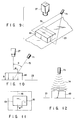
- FIG. 3 is a perspective view showing an optical reading section of FIG. 2 in more detail;
- FIG. 4 is a cross sectional view showing a height measuring unit shown in FIG. 3 in more detail;
- FIG. 5 is a block diagram showing a control circuit of the checkout device shown in FIG. 2;
- FIG. 6A is a flow chart for illustrating an operation of the checkout device shown in FIG. 2;
- FIG. 6B is a flow chart for illustrating an article registration process shown in FIG. 6A;
- FIG. 7 is a plan view showing a checkout device according to a second embodiment of this invention;
- FIG. 8 is a plan view showing a checkout device according to a third embodiment of this invention;
- FIG. 9 is a perspective view showing a first modification of the height measuring unit used in each of the above embodiments;
- FIG. 10 is a side view showing the first modification shown in FIG. 9;
- FIG. 11 shows an image for height measurement obtained by a video camera shown in FIG. 9; and
- FIG. 12 is a side view showing a second modification of the height measuring unit used in each of the above embodiments.
- There will now be described a checkout device according to a first embodiment of this invention with reference to the accompanying drawings. For example, the checkout device is used in a POS system installed in a large-scale retail store such as a supermarket.
- FIG. 2 shows the plane structure of the checkout device. The checkout device has two checkout lanes L1 and L2 arranged substantially in parallel and an
electronic cash register 67 disposed between the checkout lanes L1 and L2. Each of the checkout lanes L1 and L2 has anoptical reading section 21, basket table 22,belt conveyor 23,article stacker 29,monitor display 30,start button 31,end button 32,guidance display 33, guidance speaker SP andarticle rejecting gate 34. - The basket table 22 is used to permit a
basket 61 containingarticles 63 to be placed thereon. The guidance display 33 and guidance speaker SP output a guidance message to acustomer 62 in the form of image and voice, respectively. Thestart button 31 andend button 32 are operated by thecustomer 62 to instruct the start and end of the article registration, respectively. Thebelt conveyor 23 is laid between the basket table 22 and thearticle stacker 29 to convey thearticle 62 from thearticle placing area 24 near the basket table 22 towards thearticle stacker 29. Atunnel 25 partly covers theconveyor 23 on the downstream side from thearticle placing area 24. Theoptical reading section 21 is arranged in thetunnel 25 to detect thearticle 63 conveyed into thetunnel 25 by thebelt conveyor 23 and read the article code affixed to thearticle 63 in the bar code form. Thearticle rejecting gate 34 selectively rejects or discharges thearticle 63 conveyed out from thetunnel 25 by thebelt conveyor 23 to an article table 64 adjacent to thebelt conveyor 23. The article table 64 is formed as the upper surface of theelectronic cash register 67 set at the same height as that of thebelt conveyor 23, and thearticle rejecting gate 34 is formed as an arm which rotates around a shaft set at a boundary position between thebelt conveyor 23 and the article table 64. At the time of operation of thearticle rejecting gate 34, the arm is temporarily set at right angles to thebelt conveyor 23 and returned to the home angle at which it is set in parallel to thebelt conveyor 23. Thearticle 63 is swept from thebelt conveyor 23 to the article table 64 by the movement of the arm. Thearticle stacker 29 stores thearticle 63 which is not discharged by thearticle rejecting gate 34. - The
optical reading section 21 includes aheight measuring unit 26,video camera 27 andbar code scanner 28 arranged as shown in FIG. 3. Theheight measuring unit 26 measures the height of thearticle 63 conveyed into thetunnel 25. Thevideo camera 27 obtains an image of thearticle 63 which has passed theheight measuring unit 26. Thebar code scanner 28 scans thearticle 63 which has passed thevideo camera 27 by use of a laser beam, and photoelectrically converting the laser beam reflected from thearticle 63 to read the article code in the bar code form. - The
height measuring unit 26 has two supportingpoles belt conveyor 23. As shown in FIG. 4, the supportingpole 101 has a plurality oflight emitting elements 103 arranged at a preset pitch and the supportingpole 102 has a plurality of light receivingelements 104 arranged at a preset pitch. Thelight emitting element 103 is formed of LED or the like, and the light receiving element is formed of phototransistor, photodiode or the like. The supportingpoles light emitting elements 103 will face the correspondinglight receiving elements 104. With this arrangement, light beams emitted from thelight emitting elements 103 cross the space above thebelt conveyor 23 and are made incident on the correspondinglight receiving elements 104. Theheight measuring unit 26 measures the height of thearticle 63 based on the number of those light receivingelements 104 which do not receive the light beams because of interruption of the light beams by the article when thearticle 63 crosses a curtain of the light beams and outputs height data corresponding to the result of measurement. - The
video camera 27 is fixed directly above thebelt conveyor 23 to monitor animage input area 105 set between theheight measuring unit 26 and thebar code scanner 28 and outputs image data which will be subjected to the image processing to obtain a color image of thearticle 63 lying in theimage input area 105. Thevideo camera 27 cooperates with theheight measuring unit 26 to detect that thearticle 63 is conveyed into thetunnel 25. The entry of the article is detected when at least one of the height data from theheight measuring unit 26 and image data from thevideo camera 27 is changed from the data obtained in the normal state. - As shown in FIG. 3, the
bar code scanner 28 has variable scanningoptical systems belt conveyor 23. The variable scanningoptical systems article 63 passing ascanning area 106 set on the downstream side from theimage input area 105 by use of a laser beam. The laser beam is generated by use of a laser light source such as a laser tube or semiconductor laser device. Thebar code scanner 28 is constructed to adjust the optical length, focal distance and scanning pattern of the variable scanningoptical systems - The
electronic cash register 4 is operated by anoperator 65 or cashier stationed between the checkout lanes L1 and L2 and is used as a POS terminal for registering sold articles for each of the checkout lanes L1 and L2. - The
electronic cash register 4 includes aCPU 202,ROM 204,RAM 206,interfaces controllers drivers controller 228 is connected to akeyboard 66. Theinterface 230 is connected to a host computer HC via a communication line. Theinterface 208 is connected to thestart button 31 andend button 32 of each of the lanes L1 and L2. Thecontroller 210 is connected to theguide display 33 of each of the lanes L1 and L2. Thedriver 212 is connected to the guide speaker SP of each of the lanes L1 and L2. Thedriver 214 is connected to thebelt conveyor 23 of each of the lanes L1 and L2. Theinterface 216 is connected to theheight measuring unit 26 of each of the lanes L1 and L2. Theinterface 218 is connected to thevideo camera 27 of each of the lanes L1 and L2. Theinterface 220 is connected to thebar code scanner 28 of each of the lanes L1 and L2. Thedriver 224 is connected to thearticle rejecting gate 34 of each of the lanes L1 and L2. Thecontroller 226 is connected to themonitor display 30 of each of the lanes L1 and L2 (in FIG. 5, for simplicity, the components of the lane L2 are omitted and only the components of the lane L1 are shown). - The
CPU 202 controls the whole operations of theelectronic cash register 4 and the checkout lanes L1 and L2. TheROM 204 stores fixed data such as printing character font, display character font and the control program of theCPU 202, and theRAM 206 stores various data input to or output from theCPU 202. Specifically, theRAM 206 has a data base area for storing article data, feature data and sales data of various articles as a data base DB, a video memory area for storing image data VD, a work area for storing various guidance messages, height data, read article codes, key input article codes, and other work data WK, a counter area constructing a first counter CT1 for counting the number of conveyed-in articles, and a counter area constructing a second counter CT2 for counting the number of registered articles. The article data represents the article code, article name, unit price and the like, the feature data represents features of items such as the size (including the projected area), shape and color. The feature of color is represented by monochromatic information, color component information representing red, green and blue, chromatic information representing hue, brightness and chroma, or other information. The feature data may be omitted in some cases, for example, the feature data for fresh provisions may be omitted. - The
interface 218 receives the data base DB supplied from the host computer HC to store the same into the data base area of theRAM 206. Theinterface 218 receives the start instruction and end instruction of the article registration respectively supplied from thestart button 31 andend button 32. Thecontroller 210 controls theguidance display 33 to output an image of the guidance message. Thedriver 212 drives the speaker SP to output a voice of guidance message. Thedriver 214 drives thebelt conveyor 23. Theinterface 216 receives height data supplied from theheight measuring unit 26 to store the same into the work area of theRAM 206. Theinterface 218 receives image data VD supplied from thevideo camera 27 to store the same into the video memory area. Theinterface 220 receives a read article code supplied from thebar code scanner 28 to store the same into the work area of theRAM 206. Thedriver 224 drives thearticle rejecting gate 34. Thecontroller 226 drives themonitor display 30 to output the total amount for sold articles. Thecontroller 228 receives an article code and other input data supplied from thekeyboard 66. Thekeyboard 66 has a plurality of key pads for generating different article codes. Further, thecontroller 228 can be connected to a small-sized stationary scanner, touch scanner or pen scanner in addition to thekeyboard 66. - An operation of the above checkout device is explained below.
- When electric power is supplied to the checkout device, the
CPU 202 executes the control program stored in theROM 204 to perform a control process shown in FIG. 6A for each of the checkout lanes L1 and L2 in a time-sharing fashion, for example. - If the components are initialized at the starting time of the process, whether the
start button 31 is depressed or not is repeatedly checked in the step S1. If it is detected that thestart button 31 is depressed, theCPU 202 performs in the step S2 a control of causing thedisplay 33 and speaker SP to output guidance messages, driving thebelt conveyor 23, and clearing the contents of the counters CT1 and CT2. Then, the step S3 is repeatedly executed to check whether the entry of the article is detected or not. If the entry of the article is detected based on a change in at least one of height data from theheight measuring unit 26 and image data from thevideo camera 27, the feature extraction process is performed in the step S4. - In the feature extraction process, the
CPU 202 extracts physical features of the article placed on the conveyor from the height data generated by theheight measuring unit 26 and the image data generated by thevideo camera 27. The physical features of the article include not only the feature items such as the size, shape and color but also the feature items such as the location, height and bar code position in theimage input area 105. The location of the article is determined by taking the orientation and inclination of the article into consideration. Further, theCPU 202 determines the effective scanning range based on the article conveying position and the above physical features, and determines the optimum optical length, focal distance and scanning pattern of each of the variable scanningoptical systems - After the feature extraction process, the
CPU 202 increments the content of the counter CT1 by "1" in the step S5, performs an article registration process in the step S6, and checks in the step S7 whether theend button 32 is depressed or not. If it is detected that theend button 32 is not depressed, the steps S3 to S7 are repeatedly executed for article registration. On the other hand, if it is detected that theend button 32 is depressed, whether or not CT1 (the number of conveyed-in articles) is equal to CT2 (the number of registered articles) is checked in the step S8. If the compared two values are not equal to each other, theCPU 202 enables an article code to be entered from thekeyboard 66 in the step S9, registers an article identified by the entered article code as a sold article in the step S10, and increments the content of the counter CT2 by "1" in the step S11. If it is detected in the step S8 that CT1 is equal to CT2, thebelt conveyor 23 is stopped in the step S12, theCPU 202 calculates the total sales amount in the step S13 and displays the same on thedisplay 30. After display of the total sales amount, the step S1 is executed again for the next checkout. - FIG. 6B shows the article registration process performed in the step S6 in more detail.
- If the article registration process is started, the
bar code scanner 28 is controlled based on the results of the feature extraction process. Then, the optical length, focal distance and scanning pattern of each of the variable scanningoptical systems bar code scanner 28 are set to optimum values to scan the effective scanning area of the article passing through thescanning area 106. Thus, thebar code scanner 28 reads the article code affixed to the article in the bar code form with high probability. In the succeeding step S21, whether thebar code scanner 28 successfully has read the article code or not is checked. If it is detected that the article code reading is successful, theCPU 202 registers an article identified by the read article code as a sold article in the step S22 and increments the content of the counter CT2 by "1" in the step S23. After this, theCPU 202 obtains feature data of the article identified by the read article code from the data base in the step S24 and compares the features represented by the feature data with corresponding features contained in the results of the feature extraction process. In the step S25, whether or not there is a difference between the compared features is checked. If there is no difference between them, the article registration process is terminated. On the other hand, if there is a difference between them, the feature data is changed in the data base to additionally represent the different feature as a selectable feature in the step S26 and the article registration process is terminated after the step S26. - If it is detected in the step S21 that the
bar code scanner 28 fails to read the article code, theCPU 202 informs the operator of theelectronic cash register 4 of the failure by use of a lamp, for example, and searches the data base for feature data representing features which are sufficiently similar to the features contained in the results of the feature extraction process to identify the article. In the step S28, whether or not the article is identified in the step S27 is checked. If the article has been identified, the identified article is registered as a sold article in the step S29 and the content of the counter CT2 is incremented by "1" in the step S30. The article registration process is terminated after the step S30. On the other hand, if it is detected in the step S28 that the article is not identified, theCPU 202 drives the article rejecting gate to discharge the article from thebelt conveyor 23 in the step S31 and then terminates the article registration process. - In the checkout device of the above embodiment, the
customer 62 goes to the first checkout lane L1 as shown in FIG. 2, for example, and then places thebasket 61 containing articles to be purchased, on the basket table 22. At this time, theguidance display 33 previously displays the guidance message suggesting that thestart button 31 should be depressed to start the checkout operation. The guidance message is also informed to thecustomer 62 in a voice. - When the
customer 62 depresses thestart button 31 according to the guidance, thebelt conveyor 23 is driven and the guidance message is transmitted to thecustomer 62 by display and voice to instruct thecustomer 62 to place thearticle 63 on the placingarea 24 of thebelt conveyor 23 with the bar code set to face upward or sideways. Thecustomer 62 takes outarticles 63 one by one from thebasket 61, recognizes the position of the bar code affixed to thearticle 63, and places thearticle 63 in the specified position on the placingarea 24. Theguidance display 33 and speaker SP also inform that theend button 32 should be depressed when all of thearticles 63 to be purchased are placed. - The
article 63 on the placingarea 24 is conveyed into thetunnel 25 by thebelt conveyor 23. In thetunnel 25, the height of thearticle 63 is measured by theheight measuring unit 26, the image of thearticle 23 is obtained by thevideo camera 27, and the effective scanning area of thearticle 23 is scanned by thebar code scanner 28. When the article code is derived from thebar code scanner 28, theelectronic cash register 4 registers an article identified by the article code as a sold article, and when the article code cannot be derived, it registers the article as a sold article by extracting physical features of thearticle 63 from data derived by theheight measuring unit 26 andvideo camera 27 and searching the data base for feature data representing features which are sufficiently similar to the extracted features. - When the
unregistered article 63 is conveyed out from thetunnel 25, thearticle rejecting gate 34 discharges theunregistered article 63 from thebelt conveyor 23 to the article table 64. Further, when the registeredarticle 63 is conveyed out from thetunnel 25, the registered article is conveyed to thearticle stacker 29 without being discharged by thearticle rejecting gate 34. - The
unregistered article 63 is taken out from the article table 64 by theoperator 65, and after registered by use of thekeyboard 66, it is placed back on thebelt conveyor 23. - When the
customer 62 depresses theend button 32 after placing all of the purchasedarticles 63 on the placingarea 24, theguidance display 33 and speaker SP instruct thecustomer 62 to move forward with theempty basket 61 by display and voice. Thedisplay 30 displays the total amount for all of the sold articles for thecustomer 62. - The
customer 62 recognizes the amount of payment based on the display content of thedisplay 30 and pays money for the amount to theoperator 65. For example, theoperator 65 issues a receipt using a printer and puts the money paid by the customer into a drawer. Thecustomer 62 puts thearticles 63 stored on thestacker 29 into a bag after the payment and leaves the checkout device. - In the above embodiment, a case wherein the checkout device performs the registration of articles sold to the customer on the checkout lane L1 side is explained, but the checkout device performs the registration of articles sold to a customer on the checkout lane L2 side in the same manner as described above.
- Further, since the
electronic cash register 4 is commonly used for the checkout lanes L1 and L2, theoperator 65 selects one of the checkout lanes L1 and L2 by operation of thekeyboard 66. - It is also possible to use an automatic bagging machine to automatically put articles into a bag instead of bagging by the customer. In this case, the
article stacker 29 becomes unnecessary and articles are automatically put into a bag from thebelt conveyor 23. - Further, the checkout device can be so designed as to register physical features for identification of an article into the data base, for example, by using a small-sized camera which obtains the image of an unregistered article supplied to the
operator 65 for registration and inputs the image to theelectronic cash register 4 as image data. - In the checkout device of the above embodiment, the
belt conveyor 23 conveys the article to pass thebar code scanner 28. Therefore, no operator is required for reading the article code. Further, theheight measuring unit 26,video camera 27 andCPU 202 are used to detect the physical features of thearticle 63 placed on thebelt conveyor 23 and optimize at least the scanning pattern of thebar code scanner 28 based on the detected physical features. Therefore, if thearticle 63 is placed on thebelt conveyor 23 with the article code exposed to the outside, the article code of the article can be read with high reliability even when the positional relation between thearticle 63 and thebar code scanner 28 is changed with the movement of thebelt conveyor 23. - Even if the
bar code scanner 28 fails to read the article code, the checkout device can identify an article by comparing the features derived from the data produced by theheight measuring unit 26 and thevideo camera 27 with those contained in the data base. Therefore, it is possible to reduce the number of articles to be supplied to theoperator 65 for registration. - Further, in the checkout device, no conventional partition rod is required since customers can be separated from each other by use of the start and end
buttons - A checkout device according to a second embodiment of the present invention will be described with reference to FIG. 7. The arrangement of the checkout device is similar to that in the first embodiment except the following points. In FIG. 7, similar components are represented by the same numerals so as to omit repetitive description.
- In the checkout device, the
belt conveyor 23 of each checkout lane is formed of an entry belt conveyor 23a and anoutfeed belt conveyor 23b which are arranged in series between the basket table 22 and thearticle stacker 29. The speeds of thebelt conveyors 23a and 23b can be controlled independently. - The
article placing area 24 is set on the entry belt conveyor 23a, and thetunnel 25 is set to partly cover theoutfeed belt conveyor 23b. The entry belt conveyor 23a conveys an article from thearticle placing area 24 to the entrance of thetunnel 25, and theoutfeed belt conveyor 23b conveys the article from the entrance of thetunnel 25 to thearticle stacker 29. - The speed of the entry belt conveyor 23a is normally set such that the
customer 62 can easily place anarticle 63, and the speed of theoutfeed belt conveyor 23b is set equal to or higher than that of theentry belt conveyor 23. In a case where thearticle 63 has a large surface area, it is difficult to determine the position of the bar code affixed to thearticle 23 in the image processing of the image data from thevideo camera 27. In this case, thebar code scanner 28 takes a long period of time to read the bar code. Accordingly, the speed of theoutfeed belt conveyor 23b is temporarily decreased so that thearticle 63 can pass thescanning area 106 slowly. When the next article is conveyed into thetunnel 25 by the conveyor 23a, the next article is detected by means of theheight measuring unit 26 and thevideo camera 27. At this time, theCPU 202 performs a control of terminating the reading operation currently performed by thebar code scanner 28, increasing the speed of theoutfeed belt conveyor 23b to the normal state, and driving thearticle rejecting gate 34 so as to discharge theformer article 63 whose article code has not been read to the article table 64 from theoutfeed conveyor 23b after the article is conveyed out from thetunnel 25. When the article code is successfully read by thebar code scanner 28 before detection of the next article, the speed of theoutfeed conveyor 23b is increased to the normal state immediately. - If the customer hesitates to place the next article on the
article placing area 24, the placement of this article is delayed and theformer article 63 may reach thearticle stacker 29 or the article table 64 before the next article is detected by means of theheight measuring unit 26 and thevideo camera 27. In this case, the entry belt conveyor 23a is temporarily set at a higher speed after confirming that theend button 32 has not been depressed, and resumed to the normal speed when the next article is detected by means of theheight measuring unit 26 and thevideo camera 27. Thus, the time for conveying thearticle 63 can be shortened without reducing the reliability in the reading operation of thebar code scanner 28. - When the
end button 32 is detected to be depressed, the speeds of the entry andoutfeed conveyors 23a and 23b are increased so that the registration ofarticle 63 conveyed by theseconveyors 23a and 23b can be completed earlier. - According to the second embodiment, the same effects as described in the first embodiment can be obtained. In addition, the
article 63 can be conveyed at a more appropriate speed. - Next, a checkout device according to a third embodiment of the present invention will be described with reference to FIG. 8. The arrangement of the checkout device is similar to that in the first embodiment except the following points. In FIG. 8, similar components are represented by the same numerals so as to omit repetitive description.
- In the checkout device, each of the checkout lanes L1 and L2 further includes an
subsidiary belt conveyor 35. The basket table 22 is disposed in the vicinity of an end of thebelt conveyor 35. A guidance display 33a of a panel type is provided instead of theguidance display 33 shown in FIG. 2. Thesubsidiary belt conveyor 35 is used for directly conveying to the article table 64 an article who has no article code affixed thereto in the bar code form. - The
customer 62 checks whether thearticle 63 taken out from thebasket 61 has a bar code affixed thereto, and places thearticle 63 on thebelt conveyor 23 when thearticle 63 has the bar code and on thesubsidiary belt conveyor 35 when the article has no bar code. After theconveyor 35 has conveyed thearticle 63 to the article table 64, thearticle 63 is taken out for registration by theoperator 65. - Further, the
electronic cash register 67 includesPOS keyboards keyboards tunnels 25. A printer and drawer are disposed under the article table 64. - According to the third embodiment, the same effects as described in the first embodiment can be obtained. Further, the article registration can be effected without a unnecessary time delay since the
bar code scanner 28 does not scan an article who has no bar code. Thus, operation efficiency in the article registration can be enhanced. Moreover, since thekeyboards tunnels 25, thesekeyboards - In the first to third embodiments, the checkout device uses the
height measuring unit 26 shown in FIG. 4. However, thisunit 26 is not required if alight source 71 shown in FIG. 9 is provided, for example. Thelight source 71 has a slit through which light 70 is emitted. The light 70 spreads to form a bright line extending across thebelt conveyor 23, and is applied in an oblique direction with respect to thearticle 63 conveyed by thebelt conveyor 23. In this case, the height of thearticle 63 is measured under association of thelight source 71 and thevideo camera 27. - That is, as shown in FIG. 10, if the light 70 is inclined at a preset angle ϑ with respect to the central axis of the
video camera 30, the distance w between a bright line formed by part of the light 70 projected on the upper surface of thearticle 63 and a bright line formed by part of the light 70 projected on thebelt conveyor 24 varies with the height of thearticle 63. In other words, the height h of thearticle 26 can be represented by
video camera 30 and the height h of thearticle 26 can be calculated by incorporating the value of the distance w into the above equation. - Therefore, it is not necessary to measure the height of the
article 63 independently of the processing of 2-dimensional image data from thevideo camera 27. Further, with this height measuring scheme, the height of thearticle 63 can be more precisely measured as compared with each of the above embodiments, and therefore, the variable scanningoptical systems bar code scanner 28 can be more appropriately adjusted. As a result, the reliability of the reading operation can be enhanced. Further, since the light 70 is applied to thearticle 63 in the oblique direction, it is possible to estimate a 3-dimensional image thereof. Accordingly, the possibility that thearticle 63 is identified using the data base can be increased. - Further, the
height measuring unit 26 in each embodiment may be replaced by anultrasonic sensor head 73 shown in FIG. 12, for example. Thisultrasonic sensor head 73 radiates anultrasonic wave 74 towards thebelt conveyor 23 and measures the height of thearticle 63 based on the phase difference between the radiatedultrasonic wave 74 and the ultrasonic wave reflected from the upper surface of thearticle 63. - In each embodiment, the
height measuring unit 26 has two supportingpoles light emitting elements 103 face to a plurality of light receivingelements 104. However, the arrangement of the supportingpoles light emitting elements 103 to thelight receiving elements 104. Further, thelight emitting elements 103 and thelight receiving elements 104 can be formed on one of two supportingpoles - Further, in each embodiment, the first and second counters CT1 and CT2 are provided to count the number of conveyed-in articles and the number of registered articles. The content of the first counter CT1 is cleared when the
start button 31 is depressed, and the content of the second counter CT2 is cleared when article registration for one customer is completed. Therefore, article registration for the next customer must be started after article registration for the preceding customer has been completed. However, if the checkout device has additional counters used instead of the counters CT1 and CT2 being occupied, the article registration for the next customer can be started without awaiting completion of the article registration for the preceding customer. - Further, the first and second counters CT1 and CT2 can be replaced by a single up-down counter which is incremented upon detection of a conveyed-in article and decremented upon registration of an article. In this case, the article registration for one customer is terminated after confirming that the
end button 32 has been depressed and the content of the up-down counter is "0". In addition, if another up-down counter is provided, the article registration for the next customer can be started without awaiting completion of the article registration for the preceding customer. - Further, in each embodiment, the
belt conveyor 23 is used to convey articles. However, the article can be transported by a pallet type or roller conveyor type transporting device, for example. - Moreover, in each embodiment, the checkout device includes two checkout lanes L1 and L2. However, one of the checkout lanes L1 and L2 can be eliminated. In this case, the remaining checkout lane fully occupies an operator for article registration.
- In each embodiment, the checkout device is used for registering articles sold in a supermarket. However, this device can be also used for article registration in a field such as a distribution industry and the like which manages a large number of articles.
Claims (14)
- A checkout device comprising:
a conveying section (23) for conveying articles in one direction;
an optical scanner (28) for scanning the article conveyed by said conveying section (23) with a scanning light beam to read an article code affixed thereto; and
a registration processing section (67) for registering the article based on the article code read by said optical scanner (28);
characterized in that said registration processing section (67) includes control means (26, 27, 202, 204, 206) for performing a control in which a scanning pattern of the optical scanner (28) is optimized for physical features of the article conveyed by said conveying section (23). - A checkout device according to claim 1, characterized in that said control means includes optical monitoring means (26, 27; 71, 27) for monitoring a predetermined area into which the article is conveyed by said conveying section (23), and feature extracting means (202, 204, 206) for detecting the article and extracting physical features of the article from monitoring results of said optical monitoring means (26, 27; 71, 27).
- A checkout device according to claim 2, characterized in that said optical monitoring means includes image inputting means (27) for inputting an image within the predetermined area, and said feature extracting means (202, 204, 206) includes image processing means (202, 204, 206) for processing the image from the image inputting means (27) to extract the physical features of the article.
- A checkout device according to claim 3, characterized in that said optical monitoring means further includes light source (71) means for emitting light which is applied to the predetermined area in an oblique direction and spreads to form bright line extending across the predetermined area, and said image processing means includes height measuring means (202, 204, 206) for measuring a height of the article based on a positional difference between a bright line formed by part of the light projected on a upper surface of the article and a bright line formed by part of the light projected on a surface of said conveying section (23) outside the article in an image input by said image inputting means (27).
- A checkout device according to claim 1, characterized in that said conveying section includes a first conveyor (23a) for conveying an article placed thereon and a second conveyor (23b) for conveying, via said optical scanner (28), the article supplied from said first conveyor (23a).
- A checkout device according to claim 5, characterized in that said registration processing section includes speed control means (202, 204, 206) for independently controlling the speeds of said first and second conveyors (23a, 23b).
- A checkout device according to claim 2, characterized in that said registration processing section further includes first supplemental registering means (202, 204, 206), having a data base containing items of feature data each representing a preset number of features of an article, for searching the data base for feature data representing features which are sufficiently similar to the physical features extracted by said feature extracting means (202, 204, 206) when said optical scanner (28) fails to read the article code, identifying the article based on the results of searching, and registering the identified article.
- A checkout device according to claim 7, characterized in that said registration processing section further includes supplemental inputting means (66) for inputting an article code with respect to an article which is not identified by said first supplemental registering means (202, 204, 206) and a second supplemental registering means (202, 204, 206) for registering the article identified by the article code input from said supplemental inputting means (66).
- A checkout device according to claim 7, characterized in that said first supplemental registering means includes feature registering means (202, 204, 206) for obtaining, from the data base, feature data of the article identified by the article code which is successfully read by said optical scanner (28), detecting a difference between the features represented by the feature data and corresponding features extracted by said feature extracting means (202, 204, 206), and changing the feature data in the data base to additionally represent the different feature as a selectable feature.
- A checkout device according to claim 7, characterized in that said registration processing section further includes discharging mechanism (34) for discharging, from said conveying section (23), an article which is not identified by said first supplemental registering means (202, 204, 206), and an article table (64) for receiving the article discharged by said discharging mechanism (34).
- A checkout device according to claim 10, characterized in that said registration processing section further includes an article stacker (29) for receiving an article which is not discharged from said conveying section (23) by said discharging means.
- A checkout device according to claim 10, characterized by further comprising a subsidiary conveying section (35) arranged in parallel with said conveying section (23), for conveying an article having no article code to said article table (64).
- A checkout device according to claim 1, characterized in that said registration processing section includes instruction inputting means (31, 32) for inputting start and end instructions of article registration, counting means (CT1, CT2) for counting a number of articles conveyed into a predetermined area and a number of registered articles after the start instruction is input by said instruction inputting means (31, 32), and completion detecting means (202, 204, 206) for detecting completion of article registration by confirming that the numbers of conveyed articles and registered articles counted by said counting means (CT1, CT2) are equal to each other after the end instruction is input by said instruction inputting means (31, 32).
- A checkout device according to claim 13, characterized in that said registration processing section includes additional counting means for counting the numbers of conveyed articles and registered articles instead of said counting means (CT1, CT2) in a case where the start instruction is input by said instruction inputting means (31, 32) before completion of article registration is detected by said completion detecting means (202, 204, 206).
Applications Claiming Priority (3)
| Application Number | Priority Date | Filing Date | Title |
|---|---|---|---|
| JP11719994A JP3213670B2 (en) | 1994-05-30 | 1994-05-30 | Checkout device |
| JP11719994 | 1994-05-30 | ||
| JP117199/94 | 1994-05-30 |
Publications (3)
| Publication Number | Publication Date |
|---|---|
| EP0689174A2 true EP0689174A2 (en) | 1995-12-27 |
| EP0689174A3 EP0689174A3 (en) | 1999-07-07 |
| EP0689174B1 EP0689174B1 (en) | 2003-05-07 |
Family
ID=14705851
Family Applications (1)
| Application Number | Title | Priority Date | Filing Date |
|---|---|---|---|
| EP95108209A Expired - Lifetime EP0689174B1 (en) | 1994-05-30 | 1995-05-30 | Check out device for identifying and registering articles |
Country Status (4)
| Country | Link |
|---|---|
| US (1) | US5679941A (en) |
| EP (1) | EP0689174B1 (en) |
| JP (1) | JP3213670B2 (en) |
| DE (1) | DE69530638T2 (en) |
Cited By (4)
| Publication number | Priority date | Publication date | Assignee | Title |
|---|---|---|---|---|
| EP0672993A2 (en) * | 1994-03-07 | 1995-09-20 | Jeffrey M. Novak | Automated apparatus and method for object recognition |
| EP2230650A1 (en) * | 2009-03-18 | 2010-09-22 | Wincor Nixdorf International GmbH | Method and device for recording goods |
| EP3267408A1 (en) * | 2016-07-04 | 2018-01-10 | Toshiba TEC Kabushiki Kaisha | Check-out system with merchandise reading apparatus and pos terminal |
| US20210295300A1 (en) * | 2017-12-07 | 2021-09-23 | Ncr Corporation | Displaced scanner status indicator |
Families Citing this family (52)
| Publication number | Priority date | Publication date | Assignee | Title |
|---|---|---|---|---|
| US6330973B1 (en) * | 1989-10-30 | 2001-12-18 | Symbol Technologies, Inc. | Integrated code reading systems including tunnel scanners |
| US6073846A (en) * | 1994-08-17 | 2000-06-13 | Metrologic Instruments, Inc. | Holographic laser scanning system and process and apparatus and method |
| IT1289438B1 (en) * | 1996-12-11 | 1998-10-15 | Datalogic Spa | SCANNING READER OF AN OPTICAL CODE PLACED ON A MOVING ARTICLE AND METHOD OF SCANNING OF SAID OPTICAL CODE BY MEANS OF SAID |
| US5920056A (en) * | 1997-01-23 | 1999-07-06 | United Parcel Service Of America, Inc. | Optically-guided indicia reader system for assisting in positioning a parcel on a conveyor |
| US5923017A (en) * | 1997-01-23 | 1999-07-13 | United Parcel Service Of America | Moving-light indicia reader system |
| US5979760A (en) * | 1997-06-27 | 1999-11-09 | Accu-Sort Systems, Inc. | Scanner with linear actuator based lens positioning system |
| US7028899B2 (en) * | 1999-06-07 | 2006-04-18 | Metrologic Instruments, Inc. | Method of speckle-noise pattern reduction and apparatus therefore based on reducing the temporal-coherence of the planar laser illumination beam before it illuminates the target object by applying temporal phase modulation techniques during the transmission of the plib towards the target |
| ATE196694T1 (en) * | 1997-12-24 | 2000-10-15 | Datalogic Spa | DEVICE AND METHOD FOR FOCUSING A LASER BEAM FOR OPTICAL CODES |
| DE19840455A1 (en) * | 1998-09-04 | 2000-03-09 | Sick Ag | Method for operating a bar code reader |
| US6336587B1 (en) * | 1998-10-19 | 2002-01-08 | Symbol Technologies, Inc. | Optical code reader for producing video displays and measuring physical parameters of objects |
| JP3607131B2 (en) * | 1999-05-26 | 2005-01-05 | 株式会社デンソー | Information code image capturing device, optical information reading device, and image capturing timing setting system |
| US6557764B1 (en) * | 1999-08-12 | 2003-05-06 | Hewlett-Packard Development Company, L.P. | Method and apparatus for illumination control to increase the manufacturing yield for a bar code and position reference reader in a mass storage auto-changer |
| US6726094B1 (en) * | 2000-01-19 | 2004-04-27 | Ncr Corporation | Method and apparatus for multiple format image capture for use in retail transactions |
| US6542079B1 (en) * | 2000-02-18 | 2003-04-01 | Robert A. Kahl, Sr. | Infrared detection and alarm system for bottom shelf of shopping cart |
| DE10017862C2 (en) * | 2000-04-11 | 2002-08-14 | Leuze Electronic Gmbh & Co | Optoelectronic device |
| US6637655B1 (en) * | 2000-06-08 | 2003-10-28 | Metrologic Instruments, Inc. | Automatic range adjustment techniques for stand-mountable bar code scanners |
| US6739513B1 (en) * | 2000-09-05 | 2004-05-25 | Rjs Systems International | Box detector in barcode environment |
| US7594609B2 (en) * | 2003-11-13 | 2009-09-29 | Metrologic Instruments, Inc. | Automatic digital video image capture and processing system supporting image-processing based code symbol reading during a pass-through mode of system operation at a retail point of sale (POS) station |
| US7540424B2 (en) * | 2000-11-24 | 2009-06-02 | Metrologic Instruments, Inc. | Compact bar code symbol reading system employing a complex of coplanar illumination and imaging stations for omni-directional imaging of objects within a 3D imaging volume |
| US6637893B2 (en) * | 2002-03-22 | 2003-10-28 | Accu-Sort Systems, Inc. | Presentation imaging system |
| US6805449B2 (en) * | 2002-03-22 | 2004-10-19 | Accu-Sort Systems, Inc. | Presentation imaging system |
| US7048184B2 (en) * | 2002-06-21 | 2006-05-23 | International Business Machines Corporation | Multiple self-checkout system having integrated payment device |
| US20050078775A1 (en) * | 2002-09-23 | 2005-04-14 | Martin Hellmark | Mitigating the impact of phase steps |
| US7159777B2 (en) * | 2003-04-07 | 2007-01-09 | Silverbrook Research Pty Ltd | Transparent conveyor for check-out scanning |
| US7118026B2 (en) * | 2003-06-26 | 2006-10-10 | International Business Machines Corporation | Apparatus, method, and system for positively identifying an item |
| US7367509B2 (en) * | 2004-12-29 | 2008-05-06 | Symbol Technologies, Inc. | Methods and apparatus for swipe or presentation image scanning |
| US7222785B2 (en) * | 2005-08-16 | 2007-05-29 | Toshiba Tec Kabushiki Kaisha | Commodity information registering apparatus and commodity information registering method |
| US9778093B2 (en) * | 2006-12-26 | 2017-10-03 | Toshiba Global Commerce Solutions Holdings Corporation | Determining product length for use in regulating transactions in a self-checkout conveyer system |
| GB2451073A (en) * | 2007-07-16 | 2009-01-21 | Hawk Surveillance Systems Ltd | Checkout surveillance system |
| US8109439B2 (en) * | 2008-04-08 | 2012-02-07 | Toshiba Tec Kabushiki Kaisha | Commodity registration processing apparatus |
| US8818875B2 (en) * | 2008-09-23 | 2014-08-26 | Toshiba Global Commerce Solutions Holdings Corporation | Point of sale system with item image capture and deferred invoicing capability |
| US8571298B2 (en) * | 2008-12-23 | 2013-10-29 | Datalogic ADC, Inc. | Method and apparatus for identifying and tallying objects |
| DE102011000087A1 (en) * | 2011-01-11 | 2012-07-12 | Wincor Nixdorf International Gmbh | Transport unit and method for operating the same |
| WO2012103155A2 (en) * | 2011-01-24 | 2012-08-02 | Datalogic ADC, Inc. | Systems and methods for providing feedback to a user operating an automated checkstand |
| US8657196B2 (en) * | 2011-01-24 | 2014-02-25 | Datalogic ADC, Inc. | Systems and methods of capturing security images in an automated data reader |
| US20150242833A1 (en) | 2012-08-03 | 2015-08-27 | Nec Corporation | Information processing device and screen setting method |
| JP5936993B2 (en) * | 2012-11-08 | 2016-06-22 | 東芝テック株式会社 | Product recognition apparatus and product recognition program |
| JP2014174569A (en) * | 2013-03-05 | 2014-09-22 | Toshiba Tec Corp | Information processor and program |
| JP6549558B2 (en) * | 2014-03-28 | 2019-07-24 | 日本電気株式会社 | Sales registration device, program and sales registration method |
| US10210361B1 (en) * | 2014-08-25 | 2019-02-19 | Ecr Software Corporation | Systems and methods for checkouts, scan portal, and pay station environments with improved attendant work stations |
| JP6417912B2 (en) * | 2014-12-10 | 2018-11-07 | カシオ計算機株式会社 | Product processing system, product processing method and program |
| JP6451274B2 (en) * | 2014-12-10 | 2019-01-16 | カシオ計算機株式会社 | Product processing system, product processing method and program |
| US9898633B2 (en) | 2015-04-29 | 2018-02-20 | Datalogic IP Tech, S.r.l. | Method and system for determining the position and movement of items using radio frequency data |
| CA2931901A1 (en) * | 2015-06-08 | 2016-12-08 | Wal-Mart Stores, Inc. | Systems and methods for controlling checkout belt speed |
| US9617074B2 (en) | 2015-09-08 | 2017-04-11 | Carefusion Germany 326 Gmbh | Method and picking device for storing a plurality of identical piece goods |
| US10762486B2 (en) | 2016-01-21 | 2020-09-01 | Nec Corporation | Information processing apparatus, information processing method, and non-transitory storage medium |
| JP6801676B2 (en) | 2016-01-21 | 2020-12-16 | 日本電気株式会社 | Information processing equipment, information processing methods, and programs |
| CA3052117A1 (en) * | 2017-03-30 | 2018-10-04 | Dematic Corp. | Split robotic article pick and put system |
| JP7223596B2 (en) | 2019-02-20 | 2023-02-16 | 東芝テック株式会社 | Product information reader and program |
| JP7144058B2 (en) * | 2019-08-06 | 2022-09-29 | 日本電気株式会社 | POS terminal device, POS system, image processing method and program |
| JP7328846B2 (en) | 2019-09-18 | 2023-08-17 | 東芝テック株式会社 | Symbol reader and program |
| AT526299A1 (en) * | 2022-07-06 | 2024-01-15 | Manuel Loew Beer Mba | Computer-implemented method for identifying an article, computer program product, and system |
Citations (1)
| Publication number | Priority date | Publication date | Assignee | Title |
|---|---|---|---|---|
| JPH0467291A (en) | 1990-07-09 | 1992-03-03 | Tokyo Electric Co Ltd | Checkout device |
Family Cites Families (15)
| Publication number | Priority date | Publication date | Assignee | Title |
|---|---|---|---|---|
| CH460400A (en) * | 1967-09-18 | 1968-07-31 | Zellweger Uster Ag | Method and device for the automatic identification of objects not specially marked for automatic identification in shops and warehouses |
| US3562494A (en) * | 1967-11-24 | 1971-02-09 | Fmc Corp | Code detecting and control circuit for sorting articles |
| US3734286A (en) * | 1971-12-27 | 1973-05-22 | L Simjian | Article handling apparatus |
| GB1603860A (en) * | 1977-07-23 | 1981-12-02 | Aotosystems Ltd | Conveyor systems |
| BE899018A (en) * | 1984-02-27 | 1984-06-18 | Agemetal S A | Automatic output accounting procedure for shop - has moving mat with bar code reader, weigher and photoelectric cells arranged for fraud prevention |
| US4676343A (en) * | 1984-07-09 | 1987-06-30 | Checkrobot Inc. | Self-service distribution system |
| US4792018A (en) * | 1984-07-09 | 1988-12-20 | Checkrobot Inc. | System for security processing of retailed articles |
| US4939355A (en) * | 1988-01-22 | 1990-07-03 | Spectra-Physics, Inc. | Automatic package label scanner |
| DE3813725A1 (en) * | 1988-04-22 | 1989-11-09 | Nixdorf Computer Ag | METHOD FOR THE OPTICAL SCANING OF MARKINGS ON OBJECTS AND DEVICE FOR ITS IMPLEMENTATION |
| US4920255A (en) * | 1988-10-31 | 1990-04-24 | Stephen C. Gabeler | Automatic incremental focusing scanner system |
| DE4005105A1 (en) * | 1990-02-17 | 1991-08-22 | Werner Potrafke Spezialfabrik | CHECKOUT WITH SELF-SCANNING |
| US5178234A (en) * | 1990-03-15 | 1993-01-12 | Tokyo Electric Co., Ltd. | Checkout apparatus |
| FI86487C (en) * | 1990-12-17 | 1992-08-25 | Tero Purosto | Unmanned sales desk system |
| US5199084A (en) * | 1991-08-16 | 1993-03-30 | International Business Machines Corporation | Apparatus and method for locating characters on a label |
| US5497314A (en) * | 1994-03-07 | 1996-03-05 | Novak; Jeffrey M. | Automated apparatus and method for object recognition at checkout counters |
-
1994
- 1994-05-30 JP JP11719994A patent/JP3213670B2/en not_active Expired - Lifetime
-
1995
- 1995-05-30 DE DE69530638T patent/DE69530638T2/en not_active Expired - Fee Related
- 1995-05-30 US US08/451,273 patent/US5679941A/en not_active Expired - Fee Related
- 1995-05-30 EP EP95108209A patent/EP0689174B1/en not_active Expired - Lifetime
Patent Citations (1)
| Publication number | Priority date | Publication date | Assignee | Title |
|---|---|---|---|---|
| JPH0467291A (en) | 1990-07-09 | 1992-03-03 | Tokyo Electric Co Ltd | Checkout device |
Cited By (6)
| Publication number | Priority date | Publication date | Assignee | Title |
|---|---|---|---|---|
| EP0672993A2 (en) * | 1994-03-07 | 1995-09-20 | Jeffrey M. Novak | Automated apparatus and method for object recognition |
| EP0672993A3 (en) * | 1994-03-07 | 1997-12-17 | Jeffrey M. Novak | Automated apparatus and method for object recognition |
| EP2230650A1 (en) * | 2009-03-18 | 2010-09-22 | Wincor Nixdorf International GmbH | Method and device for recording goods |
| EP3267408A1 (en) * | 2016-07-04 | 2018-01-10 | Toshiba TEC Kabushiki Kaisha | Check-out system with merchandise reading apparatus and pos terminal |
| US20210295300A1 (en) * | 2017-12-07 | 2021-09-23 | Ncr Corporation | Displaced scanner status indicator |
| US11829983B2 (en) * | 2017-12-07 | 2023-11-28 | Ncr Corporation | Displaced scanner status indicator |
Also Published As
| Publication number | Publication date |
|---|---|
| DE69530638D1 (en) | 2003-06-12 |
| JP3213670B2 (en) | 2001-10-02 |
| JPH07320146A (en) | 1995-12-08 |
| US5679941A (en) | 1997-10-21 |
| DE69530638T2 (en) | 2004-03-04 |
| EP0689174A3 (en) | 1999-07-07 |
| EP0689174B1 (en) | 2003-05-07 |
Similar Documents
| Publication | Publication Date | Title |
|---|---|---|
| US5679941A (en) | Checkout device | |
| EP0689175B1 (en) | Check out system for identifying and registering articles | |
| US20040199427A1 (en) | Automatic check-out system | |
| US5252814A (en) | Multi-scanner checkout counter using digitizer panel to determine X-Y location of scanned items | |
| CA1247241A (en) | System for security processing of retailed articles | |
| US5343025A (en) | Check-out device with activity sensor terminating article input | |
| EP0729121B1 (en) | Check-out device | |
| EP0446929B1 (en) | Checkout apparatus | |
| US9378397B2 (en) | Portal data reader indicator light control | |
| KR101807205B1 (en) | Unattended payment device, Method for controlling the device, computer program for executing the method, and Apparatus for controlling the device | |
| KR20130139853A (en) | A checkout counter | |
| KR101998525B1 (en) | Unmanned checkout counter | |
| US8960549B2 (en) | Method, apparatus and system for scanning an optical code | |
| JP6451274B2 (en) | Product processing system, product processing method and program | |
| KR101793224B1 (en) | Unattended payment device, Method for controlling the device, computer program for executing the method, and Apparatus for controlling the device | |
| JPH08178620A (en) | Automatic bar code recognition device | |
| EP0036769A1 (en) | Checkout system | |
| USRE35455E (en) | Checkout apparatus | |
| JPH1021323A (en) | Bar code reader | |
| JPH08182002A (en) | Object recognition device | |
| JP2595336B2 (en) | Checkout device | |
| JPH06314350A (en) | Bar code scanner | |
| AU2002315954A1 (en) | Automatic check-out system | |
| JPH0896063A (en) | Comodity information reader | |
| JP2734727B2 (en) | Barcode reader |
Legal Events
| Date | Code | Title | Description |
|---|---|---|---|
| PUAI | Public reference made under article 153(3) epc to a published international application that has entered the european phase |
Free format text: ORIGINAL CODE: 0009012 |
|
| AK | Designated contracting states |
Kind code of ref document: A2 Designated state(s): DE FR GB |
|
| PUAL | Search report despatched |
Free format text: ORIGINAL CODE: 0009013 |
|
| RAP1 | Party data changed (applicant data changed or rights of an application transferred) |
Owner name: TOSHIBA TEC KABUSHIKI KAISHA |
|
| AK | Designated contracting states |
Kind code of ref document: A3 Designated state(s): DE FR GB |
|
| 17P | Request for examination filed |
Effective date: 19990908 |
|
| 17Q | First examination report despatched |
Effective date: 20010508 |
|
| GRAH | Despatch of communication of intention to grant a patent |
Free format text: ORIGINAL CODE: EPIDOS IGRA |
|
| RTI1 | Title (correction) |
Free format text: CHECK OUT DEVICE FOR IDENTIFYING AND REGISTERING ARTICLES |
|
| GRAH | Despatch of communication of intention to grant a patent |
Free format text: ORIGINAL CODE: EPIDOS IGRA |
|
| GRAH | Despatch of communication of intention to grant a patent |
Free format text: ORIGINAL CODE: EPIDOS IGRA |
|
| GRAA | (expected) grant |
Free format text: ORIGINAL CODE: 0009210 |
|
| AK | Designated contracting states |
Designated state(s): DE FR GB |
|
| REG | Reference to a national code |
Ref country code: GB Ref legal event code: FG4D |
|
| REF | Corresponds to: |
Ref document number: 69530638 Country of ref document: DE Date of ref document: 20030612 Kind code of ref document: P |
|
| ET | Fr: translation filed | ||
| PLBE | No opposition filed within time limit |
Free format text: ORIGINAL CODE: 0009261 |
|
| STAA | Information on the status of an ep patent application or granted ep patent |
Free format text: STATUS: NO OPPOSITION FILED WITHIN TIME LIMIT |
|
| 26N | No opposition filed |
Effective date: 20040210 |
|
| PGFP | Annual fee paid to national office [announced via postgrant information from national office to epo] |
Ref country code: DE Payment date: 20080605 Year of fee payment: 14 |
|
| PGFP | Annual fee paid to national office [announced via postgrant information from national office to epo] |
Ref country code: GB Payment date: 20080604 Year of fee payment: 14 |
|
| GBPC | Gb: european patent ceased through non-payment of renewal fee |
Effective date: 20090530 |
|
| REG | Reference to a national code |
Ref country code: FR Ref legal event code: ST Effective date: 20100129 |
|
| PG25 | Lapsed in a contracting state [announced via postgrant information from national office to epo] |
Ref country code: FR Free format text: LAPSE BECAUSE OF NON-PAYMENT OF DUE FEES Effective date: 20090602 |
|
| PGFP | Annual fee paid to national office [announced via postgrant information from national office to epo] |
Ref country code: FR Payment date: 20080514 Year of fee payment: 14 |
|
| PG25 | Lapsed in a contracting state [announced via postgrant information from national office to epo] |
Ref country code: GB Free format text: LAPSE BECAUSE OF NON-PAYMENT OF DUE FEES Effective date: 20090530 |
|
| PG25 | Lapsed in a contracting state [announced via postgrant information from national office to epo] |
Ref country code: DE Free format text: LAPSE BECAUSE OF NON-PAYMENT OF DUE FEES Effective date: 20091201 |