EP0688939A2 - Cylinder head assembly for a multi-value internal combustion engine of an overhead camshaft type - Google Patents
Cylinder head assembly for a multi-value internal combustion engine of an overhead camshaft type Download PDFInfo
- Publication number
- EP0688939A2 EP0688939A2 EP94111176A EP94111176A EP0688939A2 EP 0688939 A2 EP0688939 A2 EP 0688939A2 EP 94111176 A EP94111176 A EP 94111176A EP 94111176 A EP94111176 A EP 94111176A EP 0688939 A2 EP0688939 A2 EP 0688939A2
- Authority
- EP
- European Patent Office
- Prior art keywords
- cylinder head
- internal combustion
- combustion engine
- camshaft
- valves
- Prior art date
- Legal status (The legal status is an assumption and is not a legal conclusion. Google has not performed a legal analysis and makes no representation as to the accuracy of the status listed.)
- Granted
Links
Images


Classifications
-
- F—MECHANICAL ENGINEERING; LIGHTING; HEATING; WEAPONS; BLASTING
- F01—MACHINES OR ENGINES IN GENERAL; ENGINE PLANTS IN GENERAL; STEAM ENGINES
- F01L—CYCLICALLY OPERATING VALVES FOR MACHINES OR ENGINES
- F01L1/00—Valve-gear or valve arrangements, e.g. lift-valve gear
- F01L1/26—Valve-gear or valve arrangements, e.g. lift-valve gear characterised by the provision of two or more valves operated simultaneously by same transmitting-gear; peculiar to machines or engines with more than two lift-valves per cylinder
- F01L1/265—Valve-gear or valve arrangements, e.g. lift-valve gear characterised by the provision of two or more valves operated simultaneously by same transmitting-gear; peculiar to machines or engines with more than two lift-valves per cylinder peculiar to machines or engines with three or more intake valves per cylinder
-
- F—MECHANICAL ENGINEERING; LIGHTING; HEATING; WEAPONS; BLASTING
- F01—MACHINES OR ENGINES IN GENERAL; ENGINE PLANTS IN GENERAL; STEAM ENGINES
- F01L—CYCLICALLY OPERATING VALVES FOR MACHINES OR ENGINES
- F01L1/00—Valve-gear or valve arrangements, e.g. lift-valve gear
- F01L1/02—Valve drive
- F01L1/04—Valve drive by means of cams, camshafts, cam discs, eccentrics or the like
- F01L1/047—Camshafts
- F01L1/053—Camshafts overhead type
- F01L1/0532—Camshafts overhead type the cams being directly in contact with the driven valve
-
- F—MECHANICAL ENGINEERING; LIGHTING; HEATING; WEAPONS; BLASTING
- F01—MACHINES OR ENGINES IN GENERAL; ENGINE PLANTS IN GENERAL; STEAM ENGINES
- F01M—LUBRICATING OF MACHINES OR ENGINES IN GENERAL; LUBRICATING INTERNAL COMBUSTION ENGINES; CRANKCASE VENTILATING
- F01M9/00—Lubrication means having pertinent characteristics not provided for in, or of interest apart from, groups F01M1/00 - F01M7/00
- F01M9/10—Lubrication of valve gear or auxiliaries
- F01M9/105—Lubrication of valve gear or auxiliaries using distribution conduits
-
- F—MECHANICAL ENGINEERING; LIGHTING; HEATING; WEAPONS; BLASTING
- F01—MACHINES OR ENGINES IN GENERAL; ENGINE PLANTS IN GENERAL; STEAM ENGINES
- F01M—LUBRICATING OF MACHINES OR ENGINES IN GENERAL; LUBRICATING INTERNAL COMBUSTION ENGINES; CRANKCASE VENTILATING
- F01M9/00—Lubrication means having pertinent characteristics not provided for in, or of interest apart from, groups F01M1/00 - F01M7/00
- F01M9/10—Lubrication of valve gear or auxiliaries
- F01M9/101—Lubrication of valve gear or auxiliaries of cam surfaces
-
- F—MECHANICAL ENGINEERING; LIGHTING; HEATING; WEAPONS; BLASTING
- F01—MACHINES OR ENGINES IN GENERAL; ENGINE PLANTS IN GENERAL; STEAM ENGINES
- F01M—LUBRICATING OF MACHINES OR ENGINES IN GENERAL; LUBRICATING INTERNAL COMBUSTION ENGINES; CRANKCASE VENTILATING
- F01M9/00—Lubrication means having pertinent characteristics not provided for in, or of interest apart from, groups F01M1/00 - F01M7/00
- F01M9/10—Lubrication of valve gear or auxiliaries
- F01M9/102—Lubrication of valve gear or auxiliaries of camshaft bearings
-
- F—MECHANICAL ENGINEERING; LIGHTING; HEATING; WEAPONS; BLASTING
- F02—COMBUSTION ENGINES; HOT-GAS OR COMBUSTION-PRODUCT ENGINE PLANTS
- F02B—INTERNAL-COMBUSTION PISTON ENGINES; COMBUSTION ENGINES IN GENERAL
- F02B75/00—Other engines
- F02B75/02—Engines characterised by their cycles, e.g. six-stroke
- F02B2075/022—Engines characterised by their cycles, e.g. six-stroke having less than six strokes per cycle
- F02B2075/027—Engines characterised by their cycles, e.g. six-stroke having less than six strokes per cycle four
-
- F—MECHANICAL ENGINEERING; LIGHTING; HEATING; WEAPONS; BLASTING
- F02—COMBUSTION ENGINES; HOT-GAS OR COMBUSTION-PRODUCT ENGINE PLANTS
- F02B—INTERNAL-COMBUSTION PISTON ENGINES; COMBUSTION ENGINES IN GENERAL
- F02B75/00—Other engines
- F02B75/16—Engines characterised by number of cylinders, e.g. single-cylinder engines
- F02B75/18—Multi-cylinder engines
- F02B2075/1804—Number of cylinders
- F02B2075/1808—Number of cylinders two
-
- F—MECHANICAL ENGINEERING; LIGHTING; HEATING; WEAPONS; BLASTING
- F02—COMBUSTION ENGINES; HOT-GAS OR COMBUSTION-PRODUCT ENGINE PLANTS
- F02B—INTERNAL-COMBUSTION PISTON ENGINES; COMBUSTION ENGINES IN GENERAL
- F02B2275/00—Other engines, components or details, not provided for in other groups of this subclass
- F02B2275/18—DOHC [Double overhead camshaft]
Abstract
Description
- This invention relates to an internal combustion engine and more particularly to an improved clyinder head arrangement for an overhead cam, multiple valve per cylinder engine.
- It is well recognized that the performance of an internal combustion engine can be significantly improved through the use of overhead valves. Further improvements can be realized if the overhead valves are operated by overhead mounted cam shafts and if multiple valves are employed per cylinder of the engine. However, the use of multiple valve overhead cam, internal combustion engines provide very complicated cylinder head assemblies. In addition to providing sliding support for the reciprocal motion of the valves and the porting associated therewith, it is also necessary to provide bearing support for the cam shafts and/or tappet bodies which may be interposed between the cam shafts and the valves for their actuation. If all of these bearings and passages are formed in a single cylinder head casting, the casting becomes very difficult to form and many difficult machining operations are required.
- It has, therefore, been proposed to provide an overhead valve engine wherein the main cylinder head forms the support for the valves but a separate cam carrier is employed which provides the bearing surface for the tappets and/or cam shaft. Of course, with such an arrangement, it must be insured that the cam carrier is adequately affixed to the cylinder head and properly located. This requires the formation of machined surfaces between the cam carrier and the cylinder head.
- In the conventional types of structures employing separate cam carriers, either the cylinder head is formed with a machined surface that extends generally parallel to its lower seating surface and the cam carrier is fastened to this machined surface or the cylinder head is provided with a machined surface that extends perpendicularly to the stems of the valves which are operated by the tappets and/or cam carried by the cam carrier.
- Where, however, multiple valves are employed per cylinder, it may be desirable to position the reciprocal axes for the valves in directions that do not lie in a common plane. With this type of arrangement, it has been the practice to use a mounting surface that extends parallel to the lower sealing surface of the cylinder head. However, this requires complicated machining operation and actually has the mounting surface of the cam carrier disposed at an angle to the tappet bores which is not particularly desirable.
- Where valves are provided that are disposed at different reciprocal angles, it may be possible to simplify the construction of the cam carrier if its mounting surface is disposed so that it is perpendicular to the stems of one of the valves operated by the associated cam shaft. If there are more than two valves and two of these valves have parallel reciprocal axes, then there is an advantage to choose the perpendicular relationship to the greater number of valves.
- However, in addition to the actual machining of the mounting surfaces of the cam carrier, there is still another factor to consider. It is desirable to provide a relatively low cylinder head height and where there are multiple valves per cylinder disposed at different reciprocal axes, then the question of clearance of the cam carrier and the tappets for removal of the cam carrier assembly from the cylinder head with the valves still in place is a problem.
- It is desirable in many instances to provide as large a diameter for the valve springs as possible and also, to maintain a low height, to have the valve springs inserted into the tappets. However, when this is done and the mounting surface is perpendicular to the axis of one of the valves, then a greater clearance must be provided between the spring and tappet of the other valves so as to permit ease of insertion and removal of the cam carrier and/or tappets. However, the provision of such large clearances can present problems and compromise the valve spring design. Therefore, there may be some instances when it is desirable to provide a mounting surface that is not perpendicular to the axis of either of the valves per cylinder but is disposed at an angle somewhere between these two perpendicular surface angles.
- Normally, when the use of a separate cam and/or tappet carrier is employed, it is the practice to use a plurality of separate bearing caps that are affixed to the cam carrier for journaling the cam shaft. The use of separate bearing caps has a number of disadvantages. First, it requires multiple parts and second, the individual bearing caps do not provide significant rigidity for the cylinder head. Finally, it is difficult to provide lubrication for the cam shaft bearings and cam lobes when separate bearing caps are provided. That is, in this instance, all of the oil delivery passages must be formed in the cam carrier or a multiple machining operations are required.
- Accordingly, it is an objective of the present invention to provide an internal combustion engine having an improved design of the cylinder head, in particular in view of the supporting means of the multiple valve operating structure and of the overhead camshaft.
- According to the present invention said objective is performed in that the cylinder head defines at least first and second supporting surfaces spaced from the lower surface, each of said supporting surfaces surrounding a respective one of the non parallel valve stems and that at least one camshaft bearing member journalling a camshaft means for operating the poppet valves is provided having a mounting surface affixed to a cylinder head mounting surface that is disposed at an angle in the range of the angles of the first and second support surfaces.
- Preferred embodiments of the present invention are laid down in the further dependent claims.
- In the following the present inventionn is explained in greater detail by means of several embodiments thereof in conjunction with the accompanying drawings, wherein:
- Figure 1 is a side elevational view of an internal combustion engine constructed in accordance with a first embodiment of the invention and coupled to a transmission final drive arrangement for driving a motorcycle, with a portion of the cylinder head and upper portion of the cylinder block broken away and shown in sections.
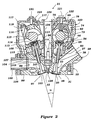
- Figure 2 is an enlarged cross sectional view of the portion of the cylinder head shown in section in Figure 1 taken along the line 2-2 of Figure 5 with the intake manifold removed.
- Figure 3 is a cross-sectional view of a portion of the cylinder head taken along the line 3-3 of Figure 5.
- Figure 4 is an enlarged top plan view of the cylinder head with the cam cover removed.
- Figure 5 is a partially exploded end elevational view of the cylinder head with the cam carrier assemblies being rotated through 90°.
- Figure 6 is a side elevational view of the cylinder head assembly looking generally in the direction of the
arrow 6 in Figure 4. - Figure 7 is an enlarged top plan view of the cam carrier and tappet body arrangement of the intake cam shaft.
- Figure 8 is a cross-sectional view taken along the line 8-8 of Figure 7 and shows how the lubricant is delivered from the cylinder head to the cam carrier tappet body assembly.
- Figure 9 is cross-sectional view taken along the line 9-9 of Figure 7 and shows how the lubricant is delivered to the individual cam lobes.
- Figure 10 is a cross-sectional view taken along the line 10-10 of Figure 7 and shows how the lubricant is delivered to the bearing surfaces of the cam shaft and tappet body and cam carrier.
- Figure 11 is a reduced scale top plan view of the cylinder head casting with the poppet body and cam carrier assembly removed.
- Figure 12 is a top plan view, in part similar to Figure 4, showing another embodiment of the invention.
- Referring now in detail to the drawings and initially to Figure 1, an internal combustion engine constructed in accordance with an embodiment of the invention is identified generally by the
reference numeral 21. Theengine 21 in the illustrated embodiment is of the two cylinder in-line type. It will be readily apparent to those skilled in the art, however, how the invention may be employed in conjunction with engines having other cylinder numbers and other cylinder configurations such as V-type and opposed types. It will be readily apparent, however, that certain facets of the invention have utility in conjunction with cylinder head assemblies that are associated with cylinder blocks having multiple cylinders. - The
engine 21 includes a cylinder head assembly, indicated generally by thereference numeral 22, and which has a construction as will be best understood by reference to the remaining figures of this embodiment. Thiscylinder head assembly 22 is affixed, in a manner which will be described, to acylinder block assembly 23 which, in turn as is typical with motorcycle practice, is affixed to a crankcase assembly 24 which also contains a change speed transmission and final drive for driving the driven wheel of the associated motorcycle in a well known manner. - The
cylinder block 23 is formed with a pair of aligned cylinder bores formed bycylinder liners 25 that are cast or pressed into thecylinder block 23 in a well known manner. Pistons 26 are slidably supported for reciprocation in each of the cylinder bores and are connected to the upper ends of respective connectingrods 27 bypiston pins 28 in a well known manner. The lower ends of these connectingrods 27 are journalled on a crankshaft contained within the crankcase transmission assembly 24 as is well known in this art. Since the invention deals with the cylinder head assembly, further description of the crankcase assembly and transmission is not believed to be necessary to understand the construction and operation of the invention. - The invention, as has been noted, deals with the construction of the
cylinder head assembly 22 and this construction will be described in more detail by reference to the remaining figures of this embodiment (Figures 2-11). Thecylinder head assembly 22 includes a main cylinder head casting, indicated generally by thereference numeral 29, which has alower sealing surface 31 that is adapted to be affixed, in the manner to be described, to thecylinder block 23 in sealing arrangement around the cylinder bores formed by theliners 25. Thislower surface 31 is provided with individualcombustion chamber recesses 32 each of which cooperates with a respective one of thepistons 26 and cylinder bores formed by theliners 25 to form a variable volume chamber, referred to hereinafter as the combustion chamber. - The
cylinder head assembly 22 is of the multiple valve type and more specifically in a preferred embodiment of the invention is of the five valve type having three intake valve and two exhaust valves per cylinder. These intake and exhaust valves are disposed in a relationship to the cylinder bore axis as described in United States Letters Patent 4,660,529, entitled 4-Cycle Engine, issued April 28, 1987 in the name of Masaaki Yoshikawa now reissued as RE33,787 on January 7, 1992, the disclosure of which is incorporated herein by reference. - The three intake valves are comprised of a center intake valve, indicated generally by the
reference numeral 33 and a pair of side intake valves, each indicated by thereference numeral 34. Thecenter intake valve 33 has ahead portion 35 that cooperates with arespective valve seat 36 positioned in the combustion chamber recess 32 of thecylinder head 29 in a known manner and formed at one end of anintake passage 37 which extends through thecylinder head casting 29 and terminates in asurface 38 in anexterior surface 38 thereof. - The
center intake valve 33 has astem portion 39 that is slidably received in a valve guide 41 suitably affixed to the cylinder head and which defines a reciprocal axis, shown at ϑc in Figure 3 which axis is disposed relative to a plane n, which will be described but which plane is parallel to a longitudinally extending plane containing the axes of the cylinder bores of theliners 25. This acute angle is relatively small as noted in the aforenoted United States Letters Patent. - The
side intake valves 34 havehead portions 42 that cooperate withrespective valve seats 43 which are affixed in thecylinder head casting 29 in the combustion chamber recess 32 and which are formed at the termination of intakegas flow passages 44 formed in thecylinder head casting 29. Thepassages cylinder head surface 38. - The
side intake valves 34 each haverespective valve stems 45 that are slidably supported about reciprocal axes defined byvalve guides 46 formed in thecylinder head casting 29 in a known manner. The valve guides 46 define respective reciprocal axes that lie in a common plane and which plane is disposed at an angle ϑs to the plane n and to the plane containing the cylinder bore axis. The angle ϑs is, as described in the aforenoted patent, a greater angle than the angle ϑc. The reciprocal axes of thecenter intake valve 33 and theside intake valves 34 intersect along a common line as also described in the aforenoted patent and which will be described later. - Referring again to Figure 1, an
intake manifold 47 is affixed to thecylinder head surface 38 through which theintake passages fuel injectors 48 that spray fuel into the openings of theintake passages combustion chamber 32 in a known manner. - A
throttle body 49 is affixed to theintake manifold 47 and contains butterflytype throttle valves 51 that are operated in a suitable manner so as to control the speed of theengine 21. Thethrottle body 49 communicates with an air inlet device such as a plenum chamber having an air inlet (not shown) in a well known manner. - The upper part of the cylinder head casting 29 is provided with a first machined
surface 52 that extends perpendicularly to the axis of thevalve stem 45 of thecenter intake valve 33. A coilcompression spring assembly 53 bears against thissurface 52 or an intervening bearing attached thereto at one end and against akeeper retainer assembly 54 that is affixed to the upper end of thevalve stem 39 at the other end for urging thecenter intake valve 33 to its closed position. In addition, the cylinder head casting 29 is provided with a pair of machine surfaces 55 that extend perpendicularly to the stems 45 of theside intake valves 34. Coil compression springs 56 bear against these surfaces andkeeper retainer assemblies 57 that are affixed to the upper ends of the stems 45 for urging theside intake valves 34 to their closed positions. - A single cam carrier and tappet body supporting member, indicated generally by the
reference numeral 58 is provided on the intake side of thecylinder head assembly 22. Thismember 58 has alower surface 59 which is machined and which is held in abutting relationship with asurface 61 of the cylinder head which is also machined. Threadedfasteners 62 affix thismember 58 to the cylinder head casting 29. - As has been previously noted, the
lower surface 59 of themember 58 and thesurface 61 of the cylinder head are disposed at an angle to the lower cylinderhead sealing surface 31. This angle is chosen to be in the range between the angles of the cylinder head machined surfaces 52 and 55 which are perpendicular to thecenter intake valve 33 orside intake valves 34, respectively. If they are chosen to be parallel to one of these perpendicular planes, there is an advantage to picking the surface that is perpendicular to the greater number of valves, in this case theside valves 34. However, as has been previously noted, this can require greater clearance between the tappet body, to be described, and the coil springs associated with the remaining intake valves. Therefore, in some embodiments it may be desirable to select an angle between the angles of the machined surfaces 52 and 55. In the illustrated embodiments, the mountingsurfaces - The
member 58 is provided with a first pair ofbores 63 which extend parallel to and are spaced outwardly from the coil springs 56 associated with theside intake valves 34.Tappets 64 are slidably supported in these bores and are engaged with adjusting shins for operating theside intake valves 34 in a manner which will be described. In a similar manner, there is provided asingle bore 65 which is parallel to and spaced outwardly from thecoil spring 53 associated with thecenter intake valve 54 and which receives atappet 66 for operating thiscenter intake valve 33. - It should be noted that the areas of the cylinder head where the
fasteners 62 are received are formed with small bores 67 (Figure 11) so as to receive locating pins for locating the cam carrier andtappet member 58 relative to the cylinder head casting 29. - The
member 58 is provided with a plurality of cylindrical recesses 69 (Figures 8 and 10) that receive the bearingportions 71 of an intake cam shaft, indicated generally by thereference numeral 72. Theintake cam shaft 72 has its rotational axis defined by these bearingsurfaces 69 and this rotational axis is coincident with the intersecting line of the axes of reciprocation of theintake valves intake cam shaft 72 is provided withcam lobes 73 that are disposed between these bearingsurfaces 71 and which engage each of thetappets intake valves - A single bearing cap, indicated generally by the
reference numeral 74 is provided with cylindrical bearing surfaces 75 that complete the journaling for the cam shaft bearing surfaces 71. Thisbearing cap 74 is provided with a plurality of spaced openings that receive threadedfasteners 76 that are tapped into tapped openings in themember 58 for affixing thebearing cap 74 to themember 58. - By providing a single
unitary bearing cap 74 for all of the cam shaft bearing surfaces 71, it is possible to rigidify the cylinder head assembly. Also, this singleunitary bearing cap 74 provides a way in which the cam shaft and tappet bodies and 66 can be lubricated. This lubrication system can be best understood by reference to Figures 6-11. - It should be noted that the cylinder head is provided with a plurality of
openings 77 that pass threaded fasteners for affixing the cylinder head casting 29 to thecylinder block 23. The center of thesepassages 77 is enlarged and provides a clearance to provide an oil passage that extends up from the cylinder block to the cylinder head. A cross drilling 78 (Figure 11) intersects thecylinder block 61 surface to which themember 58 is affixed. A drilled passage 79 (Figures 7 and 8) intersects thispassage 78 and delivers oil to themember 58. A further cross drilledpassage 81 is closed by aplug 82 and delivers the lubricant to afurther passageway 83 in which one of the set offasteners 76 is provided. Lubricant therefore can flow upwardly to apassageway 84 formed in thebearing cap 74 around this fastener. - The bearing
cap 74 is provided with a longitudinally drilledmain oil gallery 85 which is served by thispassageway 84 through afurther cross drilling 86 in thebearing cap 74 which is closed on its outer surface by aplug 87 and which intersects one of a plurality ofvertical drillings 88 formed in thebearing cap 74 and closed at their upper ends bycaps 89. Hence, lubricant is delivered to thismain oil gallery 85 at thebearing cap 74 as described. - The bearing
cap 74 is provided with drillings 91 (Figures 8 and 10) that extend from their bearingsurfaces 75 to thedrillings 88 and thus receive oil from themain oil gallery 85 and deliver it to the cam shaft bearing surfaces 71 for their lubrication. - In addition, in the areas of the
cam lobe 73, the bearingcap 74 is provided with acutaway surface 92 for clearance and adrilling 93 extends from each cutaway 92 to the main oil gallery 85 (Figures 2, 3, and 9) for delivering oil to thecam lobes 73 and also thetappets unitary bearing cap 74 provides a very effective way in which lubricant can be supplied to thecam shaft 71 andtappets - As has been previously noted, the cylinder head casting 29 is provided with
openings 77 to receive fasteners for affixing thecylinder head 29 to thecylinder block 23. The bearingcap 74 andmembers 58 is provided with a plurality ofopenings 94 through which a tool may be passed so as to facilitate tightening of these threaded fasteners without removal of the cam assembly. - The
cylinder head member 29 is provided with a cam shaft driving cavity 95 (Figures 4 and 11) at one end thereof into which theintake cam shaft 71 extends. Atiming gear 96 is affixed to theintake cam shaft 71 in thiscavity 95 and is driven in timed relationship to the engine crankshaft through a gear drive provided in part in this cavity as is well known in this art. - The intake system as thus far described and particularly the
heads intake valves exhaust passages 98 that extend from thecombustion chamber recess 32 to exhaustports 99 formed in the outer side of thecylinder head member 29. -
Exhaust valves 101 havehead portions 102 that cooperate with the exhaust valve seats 97 for controlling the flow through them. Theseexhaust valves 101 havestem portions 103 that are slidably supported within valve guides 104 fixed in thecylinder head member 29 in a known manner. Theexhaust valves 101 have theirstems 103 reciprocal about axes that lie in a common plane which plane is disposed at the angle ϑ (Figure 2) to the axis of reciprocation of the center ofintake valves 33. In addition, the reciprocal axes of theexhaust valves 71 are disposed at an angle to a vertical plane containing the cylinder bore axis and the plane n which is greater than the angle ϑc of the center intake valve and less than the angle ϑs of the side intake valves, as also described in the aforenoted patent. - An
exhaust manifold 105 is affixed to theexhaust ports 99 byfasteners 106 and discharges the exhaust gases to the atmosphere through a suitable exhaust system (not shown). Exhaust valve springs 107 encircle theexhaust valves 101 and act against machined surfaces formed in thecylinder head member 29 and keeper retainer assemblies 108 affixed to the upper ends of the valve stems 103 for urging theexhaust valves 101 to their closed positions. - A combined cam carrier and tappet body member, indicated generally by the
reference numeral 109 has a machined lower surface 111 that is engaged with a machinedupper surface 112 of thecylinder head member 29 and held thereto byfasteners 110. Thesurface 112 is perpendicular to the bearing surface for the exhaust valve springs 107 and perpendicular to the axis of the valve stems 103. Thismember 109 hasbores 113 that slidably receivetappets 64 114 for operating theexhaust valves 101 in a well known manner. - The
member 109 also is formed with bearing surfaces like those of themember 58 for journaling anexhaust cam shaft 115. Aunitary bearing cap 116 having a construction similar to that of thebearing cap 74 is affixed to themember 109 by threadedfasteners 117. Amain oil gallery 118 extends through theunitary bearing cap 116 and receives lubricant from the engine in the same manner as that described in conjunction with the intake cam shaft and, for that reason, this construction will not be described again. As with theintake cam shaft 71, the bearing surfaces, cam lobes andtappet bodies 114 on the exhaust side of the engine are lubricated in the manner as aforedescribed. - The
bearing cap 116 also hasopenings 118 disposed above the cylinder head hold downbolt hole openings 77 for permitting the fasteners to be tightened through an appropriate tool. - The
exhaust cam shaft 115 has affixed to it agear 119 in thedrive cavity 95 of thecylinder head 29 so as to permit driving of theexhaust cam shaft 115 from the engine crankshaft through the aforedescribed gear train in a well known manner. - The bearing caps 74 and 116 are each provided with tapped holes, one of which appears in Figures 2 and 3 and which receive threaded
fasteners 121 with sealinggrommets 122 for affixing acam cover 123 to thecylinder head member 29. - The
cam cover 123 is formed withopenings 124 that receivetubes 125 so as to pass spark plugs 126. The spark plugs 126 are threaded into tapped holes 127 formed centrally in thecombustion chamber recess 32 for firing the charge therein in a well known manner. - Figure 12 is a top plan view in part similar to Figure 4 and shows a slightly modified form of the invention wherein the only difference between the previously described embodiment is a reduction in the number of threaded fasteners. In this figure, where components are the same or substantially the same as those previously described they have been identified by the same reference numerals and further description of this embodiment is believed to be unnecessary.
- It should be readily apparent from the foregoing description that the described embodiments of the invention provide a very simplified cylinder head arrangement and nevertheless one in which the cylinder head casting itself can be simplified and through the use of a unitary cam carrier, tappet body and unitary bearing cap can be strong, provide good lubrication and ease of assembly. Of course, the foregoing description is that of a preferred embodiment of the invention and various changes and modifications may be made without departing from the spirit and scope of the invention, as defined by the appended claims.
Claims (17)
- Internal combustion engine of an overhead camshaft type comprising a cylinder block and a cylinder head (22) affixed to the cylinder block (23), said cylinder head (22) having a lower surface (31) sealingly engaging an upper surface of the cylinder block (23) and defining a plurality of valve seats (36,43) at the intake or exhaust side of a combustion chamber, said valve seats (36,43), which form a termination of respective flow passages (37,44) extending through said cylinder head (22), cooperate with head portions (35,42) of poppet valves (33,34) for controlling the flow through said valve seats (36,43), said poppert valves (33,34) having stem portions (39,45) slideably supported along their longitudinal axes by said cylinder head (22), wherein at least two of said longitudinal axes of the valve stems (39,45) extend in a non parallel relationship, characterised in that the cylinder head (22) defines at least first and second supporting surfaces (52,55) spaced from the lower surface (31), each of said supporting surfaces surrounding a respective one of the non parallel valve stems (39,45) and that at least one camshaft bearing member (58) journalling a camshaft means (72) for operating the poppet valves (33,34) is provided having a mounting surface (59) affixed to a cylinder head mounting surface (61) that is disposed at an angle in the range of the angles of the first and second support surfaces (52,55).
- Internal combustion engine as claimed in claim 1, characterised in that said first and second supporting surfaces (52,55) extend substantially perpendicularly to the longitudinal axis of the associated valve stems (39,45).
- Internal combustion engine as claims 1 or 2, characterised in that the cylinder head mounting surface (61) is disposed inclined with respect to the lower sealing surface (31) of the cylinder head (22), preferably at an angle which corresponds to one of the first and second support surfaces (52,55).
- Internal combustion engine as claimed in at least one of the preceding claims 1 to 3, characterised in that the first and second supporting surfaces (52,55) are adapted to be engaged by coil compression spring assemblies (55,56) for urging the associated poppert valves (33,34) in their closing positions.
- Internal combustion engine having at least three intake and two exhaust (33,34;101) valves as claimed in at least one of the preceding claims 1 to 4, characterised in that the cylinder head (22) comprises one first supporting surface (52) that extends perpendicularly to the axis of the associated valve stem (45) of a centre intake valve (33) and two second supporting surfaces (55) that extends perpendicularly to parallel valve stems (45) of the associated two side intake valves (44), said side intake valves (44) being disposed non-parallel to the centre intake valve (33).
- Internal combustion engine as claimed in claim 4, characterised in that, the camshaft bearing member (58) is disposed at the intake side of the engine and has a mounting surface (59) which extends in parallel to the second supporting surfaces (55) surrounding the valve stems (45) of the side intake valves (54), respectfully.
- Internal combustion engine as claimed in at least one of the preceding claims 1 to 6, characterised in that, the cylinder head mounting surface (61) is disposed at an angle which lies between that of the angles of the first and second supporting surfaces (52,55).
- Internal combustion engine as claimed in at least one of the preceding claims 1 to 6, characterised by a common unitary bearing cap member (74) which is affixed to the camshaft bearing member (58) and is provided with cylindrical bearing surfaces (75) that complete the journalling for bearing surfaces (71) of the camshaft (72) provided through a plurality of cylindrical recesses (69) of the camshaft bearing member (58).
- Internal combustion engine as claimed in claim 8, characterised in that the bearing cap member 874) comprises a lubricating passage means (77,85) for lubricating at least bearing surfaces (71) and cam lobes (73) of the camshaft (72).
- Internal combustion engine as claimed in claim 7 or 8, characterised in that the bearing cap member (74) has a main oil gallery (85) drilled longitudinally therethrough and cross drilled by respective passageways (86) for lubricating the bearing surfaces (71) and the cam lobes (73), and further including a passageway (77) extending through the bearing cap member (74) and the camshaft bearing member (58) and supplied with oil from the associated cylinder head (22) and intersecting the main oil gallery (85) of the bearing cap member (74).
- Internal combustion engine as claimed in at least one of the preceding claim 1 to 10, characterised by a plurality of tappet bores (63) formed in the camshaft bearing member (18), one for each poppet valve (33,34) for slideably receiving a tappet (64) for operating the respective poppet valves (33,34).
- Internal combustion engine as claimed in claim 11, characterised in that the tappet receiving bores (63) extend in parallel to the respective longitudinal axes of the valve stems (39,45) of the poppet valves (33,34).
- Internal combustion engine as claimed in claims 11 or 12, characterised in that a tappet bearing member (58) is providing having a mounting surface (59) parallel to and affixed to a mounting surface (61) of said cylinder head (22) and providing a plurality of bores (63) for receiving respective tappets (65) for operating respective of said poppet valves (33,34), said mounting surfaces (59,63) being disposed of at an angle in the range of the angles of said supporting surfaces (52,55).
- Internal combustion engine as claimed in claim 13, characterised in that the mounting surface (59) of the tappet bearing member (58) is disposed in parallel to the second supporting surface (55) of the side intake valves (34).
- Internal combustion engine as claimed in at least one of the preceding claims 1 to 14, characterised in that said cylinder head (22) having a lower surface (31) for sealing relationship with a plurality of cylinder bores of the associated clyinder block (23), a plurality of valve seats (36,43) formed in said cylinder head lower surface (31) for each of said cylinder bores at the termination of the respective gas flow passages (57,44) extending through said cylinder head (22), a plurality of poppet valves (33,34) supported for reciprocation by said cylinder head (22) and each adapted to control the flow through a respective one of said valve seats, a camshaft (72) journalled for rotation by said cylinder head (22) for operating said poppet valves (33,34) including a single bearing cap (74) having a plurality of bearing surfaces engaging bearing surfaces (71) of said camshaft (72) and detachable connected to said cylinder head (22), and a cam cover affixed (123) to said cylinder head (22) and enclosing said cam shaft (72) and said single bearing cap (74).
- Internal combustion engine as claimed in claim 15, characterised in that a lubricating passage means (85) is provided formed in the single bearing cap member (74) for lubricating the camshaft.
- Internal combustion engine as claimed in at least one of the preceding claims 1 to 15, characterised in that the camshaft bearing member (58) affixed to the cylinder head (22) and defining bearing surfaces cooperates with the bearing surfaces of the single bearing cap member (74) for journalling the camshaft (72) and provides bores (63) for receiving the tappets (64) actuated by the camshaft and for operating the poppet valves (33,34).
Applications Claiming Priority (2)
| Application Number | Priority Date | Filing Date | Title |
|---|---|---|---|
| US26033994A | 1994-06-15 | 1994-06-15 | |
| US260339 | 1994-06-15 |
Publications (3)
| Publication Number | Publication Date |
|---|---|
| EP0688939A2 true EP0688939A2 (en) | 1995-12-27 |
| EP0688939A3 EP0688939A3 (en) | 1996-05-01 |
| EP0688939B1 EP0688939B1 (en) | 1998-11-11 |
Family
ID=22988767
Family Applications (1)
| Application Number | Title | Priority Date | Filing Date |
|---|---|---|---|
| EP94111176A Expired - Lifetime EP0688939B1 (en) | 1994-06-15 | 1994-07-18 | Cylinder head assembly for a multi-value internal combustion engine of an overhead camshaft type |
Country Status (3)
| Country | Link |
|---|---|
| US (1) | US5704330A (en) |
| EP (1) | EP0688939B1 (en) |
| DE (1) | DE69414557T2 (en) |
Cited By (1)
| Publication number | Priority date | Publication date | Assignee | Title |
|---|---|---|---|---|
| EP1722075A1 (en) * | 2005-05-14 | 2006-11-15 | Bayerische Motoren Werke Aktiengesellschaft | Cylinder head |
Families Citing this family (10)
| Publication number | Priority date | Publication date | Assignee | Title |
|---|---|---|---|---|
| DE19928838C1 (en) * | 1999-06-24 | 2001-02-15 | Otmar Gaehrken | Cylinder head |
| JP4446105B2 (en) | 1999-06-25 | 2010-04-07 | ヤマハ発動機株式会社 | 4-cycle engine |
| US6293244B1 (en) * | 2000-05-09 | 2001-09-25 | Ford Global Technologies, Inc. | Oil flow control system for engine cylinder head |
| DE10250303A1 (en) * | 2002-10-29 | 2004-05-19 | Bayerische Motoren Werke Ag | Cylinder head of an internal combustion engine with a camshaft bearing strip |
| JP2004293435A (en) * | 2003-03-27 | 2004-10-21 | Honda Motor Co Ltd | Oiling structure of ohc-type internal combustion engine |
| US7377246B2 (en) * | 2005-05-04 | 2008-05-27 | Gentek Technologies Marketing Inc. | Vertically oriented camshaft cap oil diverter |
| JP4698544B2 (en) * | 2006-09-26 | 2011-06-08 | 本田技研工業株式会社 | Internal combustion engine |
| JP2011001878A (en) * | 2009-06-18 | 2011-01-06 | Jtekt Corp | Camshaft device, engine with the same, and method for manufacturing camshaft device |
| US8534251B2 (en) * | 2010-05-17 | 2013-09-17 | GM Global Technology Operations LLC | Engine assembly with camshaft housing |
| WO2014085285A2 (en) | 2012-11-27 | 2014-06-05 | Quinton Aaron S | Cylinder block with integrated oil jacket |
Citations (5)
| Publication number | Priority date | Publication date | Assignee | Title |
|---|---|---|---|---|
| EP0117850A1 (en) * | 1983-02-24 | 1984-09-05 | Mario Anfusio | Internal combustion engine of the reciprocating piston-type with multiple-valve cylinders |
| US4658780A (en) * | 1981-05-08 | 1987-04-21 | Yamaha Hatsudoki Kabushiki Kaisha | Four cycle internal combustion engine |
| US4660529A (en) * | 1981-04-22 | 1987-04-28 | Yamaha Hatsudoki Kabushiki Kaisha | Four-cycle engine |
| EP0408081A1 (en) * | 1989-07-14 | 1991-01-16 | Yamaha Hatsudoki Kabushiki Kaisha | Cylinder head lubricating system of an internal combustion engine |
| EP0462568A1 (en) * | 1990-06-19 | 1991-12-27 | FERRARI S.p.A. | Timing system, particularly for an internal combustion engine with a number of valves per cylinder |
Family Cites Families (75)
| Publication number | Priority date | Publication date | Assignee | Title |
|---|---|---|---|---|
| US1727265A (en) * | 1925-09-05 | 1929-09-03 | Gen Motors Res Corp | Charge-forming device for internal-combustion engines |
| GB652671A (en) * | 1944-12-14 | 1951-05-02 | Marius Clement Cardonaro | Improvements in or relating to carburettors for internal combustion engines |
| US3318292A (en) * | 1964-12-10 | 1967-05-09 | Ford Motor Co | Internal combustion engine |
| FR1464586A (en) * | 1965-03-27 | 1967-01-06 | Inst Francais Du Petrole | Process allowing the combustion of globally lean mixtures in positive-ignition engines and devices for its implementation |
| US3408992A (en) * | 1966-12-13 | 1968-11-05 | Ernest A. Von Seggern | Internal combustion engine and process utilizing heated auxiliary air to obtain complete combustion |
| FR1602469A (en) * | 1968-12-24 | 1970-11-30 | ||
| JPS5013725A (en) * | 1973-06-08 | 1975-02-13 | ||
| JPS5154007A (en) * | 1974-11-07 | 1976-05-12 | Nippon Electric Co | KODANSEIZAIRYONOSEIZOHOHO |
| JPS5844843B2 (en) * | 1976-03-05 | 1983-10-05 | 日産自動車株式会社 | Internal combustion engine intake passage |
| US4174686A (en) * | 1976-10-09 | 1979-11-20 | Toyo Kogyo Co., Ltd. | Intake system for internal combustion engines |
| JPS5829261B2 (en) * | 1976-12-02 | 1983-06-21 | 株式会社保谷硝子 | filter glass |
| US4207854A (en) * | 1978-01-13 | 1980-06-17 | Caterpillar Tractor Co. | Inlet air passage for an engine |
| DE2803533A1 (en) * | 1978-01-27 | 1979-08-02 | Volkswagenwerk Ag | AIR COMPRESSING, SELF-IGNING COMBUSTION ENGINE |
| GB2016081B (en) * | 1978-03-08 | 1982-07-14 | Yamaha Motor Co Ltd | Engine induction system |
| JPS581654Y2 (en) * | 1978-04-15 | 1983-01-12 | 日産自動車株式会社 | Intake system for fuel-injected internal combustion engines |
| JPS5525543A (en) * | 1978-08-10 | 1980-02-23 | Toyota Motor Corp | Intake apparatus of multicylinder internal combustion engine |
| JPS5525535A (en) * | 1978-08-10 | 1980-02-23 | Toyota Motor Corp | Intake apparatus of multicylinder internal combustion engine |
| JPS5540277A (en) * | 1978-09-18 | 1980-03-21 | Toyota Motor Corp | Intake device for internal combustion engine |
| US4228772A (en) * | 1979-02-01 | 1980-10-21 | General Motors Corporation | Low throttled volume engine |
| FR2461885A1 (en) * | 1979-07-17 | 1981-02-06 | Ind Plastiques | DEVICE FORMING ENVELOPE FOR A STACK, APPARATUS COMPRISING SAID DEVICE AND METHOD FOR MOUNTING THE SAID APPARATUS |
| JPS5643428A (en) * | 1979-09-15 | 1981-04-22 | Negishi Kogyo Kenkyusho:Kk | Spinning frame |
| JPS5830097Y2 (en) * | 1979-12-04 | 1983-07-02 | 日産自動車株式会社 | Internal combustion engine intake control device |
| JPS56113022A (en) * | 1980-02-12 | 1981-09-05 | Nissan Motor Co Ltd | Intake controlling apparatus of internal combustion engine |
| US4320725A (en) * | 1980-02-25 | 1982-03-23 | Rychlik Frank J | Puffing swirler |
| JPS56139829A (en) * | 1980-04-04 | 1981-10-31 | Bridgestone Corp | Tire molding metallic mold and production of same by electrospark machining |
| WO1982000297A1 (en) * | 1980-07-15 | 1982-02-04 | J Blackwell | Production of synthetic plastics foam material |
| JPS5783631A (en) * | 1980-11-13 | 1982-05-25 | Suzuki Motor Co Ltd | Internal combustion engine |
| DE3170899D1 (en) * | 1980-12-22 | 1985-07-11 | Yamaha Motor Co Ltd | Multi-intake valve type internal combustion engine |
| GB2100797B (en) * | 1981-06-24 | 1985-10-09 | Suzuki Motor Co | Duplex carburetor and intake system for internal combustion engines |
| JPS6014170B2 (en) * | 1981-06-29 | 1985-04-11 | トヨタ自動車株式会社 | Flow path control device for helical intake port |
| JPS6032009B2 (en) * | 1981-08-03 | 1985-07-25 | トヨタ自動車株式会社 | Helical intake port |
| GB2105783A (en) * | 1981-08-28 | 1983-03-30 | Ricardo Consulting Eng | Regulating i c engine charge swirl |
| US4663938A (en) * | 1981-09-14 | 1987-05-12 | Colgate Thermodynamics Co. | Adiabatic positive displacement machinery |
| US4465035A (en) * | 1981-09-29 | 1984-08-14 | Bretton Patents Limited | Internal combustion engine |
| DE3141880A1 (en) * | 1981-10-22 | 1983-05-11 | Audi Nsu Auto Union Ag, 7107 Neckarsulm | INJECTION COMBUSTION ENGINE, ESPECIALLY DIESEL COMBUSTION ENGINE |
| US4428334A (en) * | 1981-11-20 | 1984-01-31 | General Motors Corporation | Engine with variable flow controlled cellular intake port |
| JPS595767A (en) * | 1982-07-01 | 1984-01-12 | Nippon Telegr & Teleph Corp <Ntt> | Tone detection type connection switching system |
| JPS5958109A (en) * | 1982-09-27 | 1984-04-03 | Honda Motor Co Ltd | Cam shaft holder of internal combustion engine |
| JPS59120718A (en) * | 1982-12-27 | 1984-07-12 | Hino Motors Ltd | Swirl control device |
| JPS59122725A (en) * | 1982-12-29 | 1984-07-16 | Mazda Motor Corp | Suction device of engine |
| JPS6011206A (en) * | 1983-06-24 | 1985-01-21 | Nippon Furnace Kogyo Kaisha Ltd | Apparatus for regulating volume of oxygen enriched air and concentration of oxygen |
| JPS6036723A (en) * | 1983-08-10 | 1985-02-25 | Mazda Motor Corp | Intake apparatus for engine |
| JPS6112940A (en) * | 1984-06-22 | 1986-01-21 | 東レ株式会社 | High speed false twisting method and apparatus |
| JPS6128715A (en) * | 1984-07-17 | 1986-02-08 | Fuji Heavy Ind Ltd | Intake device of internal-combustion engine |
| FR2569227B1 (en) * | 1984-08-16 | 1988-11-18 | Renault | VARIABLE INTENSITY TURBULENCE GENERATING DEVICE FOR INTERNAL COMBUSTION ENGINE |
| JPS61144223A (en) * | 1984-12-18 | 1986-07-01 | Sankyo Alum Ind Co Ltd | Manufacture of composite curved shape |
| JPH0326265Y2 (en) * | 1984-12-20 | 1991-06-06 | ||
| US4753200A (en) * | 1985-01-29 | 1988-06-28 | Nissan Motor Company, Limited | Engine combustion control system |
| US4669434A (en) * | 1985-07-24 | 1987-06-02 | Toyota Jidosha Kabushiki Kaisha | Internal combustion engine cylinder head variable swirl siamese type intake port structure, with auxiliary straight passage, pointing at spark plug, leading from mixture intake to downstream end of straight intake port |
| US4834035A (en) * | 1985-08-23 | 1989-05-30 | Mitsubishi Jidosha Kogyo Kabushiki Kaisha | Variable swirl intake apparatus for engine |
| DE3665751D1 (en) * | 1985-10-26 | 1989-10-26 | Bayerische Motoren Werke Ag | Induction system for a spark-ignited engine with electronic fuel injection |
| JPH076395B2 (en) * | 1985-11-08 | 1995-01-30 | トヨタ自動車株式会社 | Internal combustion engine intake system |
| GB2196388B (en) * | 1986-04-02 | 1989-11-22 | Mitsubishi Motors Corp | Inlet port device |
| US4779594A (en) * | 1986-04-25 | 1988-10-25 | Mazda Motor Corporation | Intake system for an internal combustion engine |
| JPH0774610B2 (en) * | 1986-07-25 | 1995-08-09 | 三菱自動車工業株式会社 | Variable swirl generator |
| US4826561A (en) * | 1986-07-31 | 1989-05-02 | The Reinforcer, Inc. | Hole puncher and reinforcer |
| JPS6373534A (en) * | 1986-09-16 | 1988-04-04 | Matsushita Electronics Corp | Inspection method of semiconductor integrated circuit |
| JPS6373532A (en) * | 1986-09-16 | 1988-04-04 | Nec Corp | Bonding device |
| GB8625170D0 (en) * | 1986-10-21 | 1986-11-26 | Ford Motor Co | I c engines |
| JPH0410340Y2 (en) * | 1986-11-04 | 1992-03-13 | ||
| DE3641129C1 (en) * | 1986-12-02 | 1987-07-30 | Daimler Benz Ag | Device for mounting two camshafts in the cylinder head of a multi-cylinder in-line internal combustion engine |
| US4827883A (en) * | 1988-04-15 | 1989-05-09 | General Motors Corporation | Variable swirl inlet port |
| JP2597657B2 (en) * | 1988-06-28 | 1997-04-09 | 日産自動車株式会社 | Combustion chamber of internal combustion engine |
| JPH02115922A (en) * | 1988-10-25 | 1990-04-27 | Nec Corp | Mouse |
| JP2682694B2 (en) * | 1989-03-03 | 1997-11-26 | 富士重工業株式会社 | Engine intake system |
| JPH02305335A (en) * | 1989-05-17 | 1990-12-18 | Nissan Motor Co Ltd | Combustion controller of engine |
| JPH082403Y2 (en) * | 1989-05-22 | 1996-01-29 | トヨタ自動車株式会社 | Thrust bearing structure for both camshaft and assembly line |
| EP0408080B1 (en) * | 1989-07-13 | 1995-02-08 | Yamaha Hatsudoki Kabushiki Kaisha | Valve and spring arrangement for engine |
| US4974566A (en) * | 1989-09-28 | 1990-12-04 | Ford Motor Company | Optimal swirl generation by valve control |
| DE3943727C2 (en) * | 1989-12-11 | 1995-07-13 | Porsche Ag | Cylinder head of an internal combustion engine |
| GB2242226A (en) * | 1990-03-07 | 1991-09-25 | Jaguar Cars | I.C. engine intake baffle |
| GB2242228A (en) * | 1990-03-24 | 1991-09-25 | Rover Group | I.c engine charge swirl inlet arrangement |
| JPH0482343U (en) * | 1990-11-29 | 1992-07-17 | ||
| DE4116944C2 (en) * | 1991-05-24 | 1997-05-22 | Daimler Benz Ag | Cylinder head for a multi-cylinder internal combustion engine |
| JPH0586813A (en) * | 1991-09-20 | 1993-04-06 | Mazda Motor Corp | Bearing structure for camshaft |
-
1994
- 1994-07-18 DE DE69414557T patent/DE69414557T2/en not_active Expired - Fee Related
- 1994-07-18 EP EP94111176A patent/EP0688939B1/en not_active Expired - Lifetime
-
1996
- 1996-05-22 US US08/651,505 patent/US5704330A/en not_active Expired - Lifetime
Patent Citations (5)
| Publication number | Priority date | Publication date | Assignee | Title |
|---|---|---|---|---|
| US4660529A (en) * | 1981-04-22 | 1987-04-28 | Yamaha Hatsudoki Kabushiki Kaisha | Four-cycle engine |
| US4658780A (en) * | 1981-05-08 | 1987-04-21 | Yamaha Hatsudoki Kabushiki Kaisha | Four cycle internal combustion engine |
| EP0117850A1 (en) * | 1983-02-24 | 1984-09-05 | Mario Anfusio | Internal combustion engine of the reciprocating piston-type with multiple-valve cylinders |
| EP0408081A1 (en) * | 1989-07-14 | 1991-01-16 | Yamaha Hatsudoki Kabushiki Kaisha | Cylinder head lubricating system of an internal combustion engine |
| EP0462568A1 (en) * | 1990-06-19 | 1991-12-27 | FERRARI S.p.A. | Timing system, particularly for an internal combustion engine with a number of valves per cylinder |
Cited By (1)
| Publication number | Priority date | Publication date | Assignee | Title |
|---|---|---|---|---|
| EP1722075A1 (en) * | 2005-05-14 | 2006-11-15 | Bayerische Motoren Werke Aktiengesellschaft | Cylinder head |
Also Published As
| Publication number | Publication date |
|---|---|
| DE69414557T2 (en) | 1999-04-01 |
| EP0688939A3 (en) | 1996-05-01 |
| DE69414557D1 (en) | 1998-12-17 |
| EP0688939B1 (en) | 1998-11-11 |
| US5704330A (en) | 1998-01-06 |
Similar Documents
| Publication | Publication Date | Title |
|---|---|---|
| US6289861B1 (en) | Control for variable valve timing | |
| US5758612A (en) | Valve actuating structure for multi-valve engine | |
| US4637357A (en) | Tappet arrangement for engine valve train | |
| US5016592A (en) | Cylinder head and valve train arrangement for multiple valve engine | |
| EP0688939B1 (en) | Cylinder head assembly for a multi-value internal combustion engine of an overhead camshaft type | |
| EP0433728A1 (en) | Cylinder head and valve arrangement for a multi-valve internal combustion engine | |
| US6173689B1 (en) | Lubrication arrangement for engine valve actuation | |
| US4333426A (en) | Internal combustion engine construction | |
| US5099812A (en) | Cylinder head for internal combustion engine | |
| US4592314A (en) | Valve actuating mechanism for internal combustion engine | |
| US5535714A (en) | Cylinder head arrangement for multi-valve engine | |
| EP0654589B1 (en) | Cylinder head lubricating system of an internal combustion engine | |
| US4651696A (en) | Four-stroke internal combustion engine | |
| US5398649A (en) | S.O.H.C. five valve engine | |
| US4649873A (en) | Oil return system for overhead cam engine | |
| US5125374A (en) | Valve actuating arrangement for engine | |
| US6035821A (en) | Cam shaft for engine | |
| US4572117A (en) | Valve arrangement for an internal combustion engine | |
| US5101777A (en) | Automobile engine structure | |
| US5018497A (en) | Multiple valve internal combustion engine | |
| USRE35382E (en) | Lubrication arrangement for engine | |
| US5906186A (en) | Cylinder head for tappet arrangement for multi-valve engine | |
| US5522354A (en) | Valve mechanism for internal combustion engine | |
| US6189503B1 (en) | Porting arrangement for direct injected engine | |
| US5119776A (en) | Compact bearing cap for overhead camshaft |
Legal Events
| Date | Code | Title | Description |
|---|---|---|---|
| PUAI | Public reference made under article 153(3) epc to a published international application that has entered the european phase |
Free format text: ORIGINAL CODE: 0009012 |
|
| AK | Designated contracting states |
Kind code of ref document: A2 Designated state(s): DE FR GB |
|
| PUAL | Search report despatched |
Free format text: ORIGINAL CODE: 0009013 |
|
| AK | Designated contracting states |
Kind code of ref document: A3 Designated state(s): DE FR GB |
|
| 17P | Request for examination filed |
Effective date: 19961031 |
|
| 17Q | First examination report despatched |
Effective date: 19970213 |
|
| GRAG | Despatch of communication of intention to grant |
Free format text: ORIGINAL CODE: EPIDOS AGRA |
|
| GRAG | Despatch of communication of intention to grant |
Free format text: ORIGINAL CODE: EPIDOS AGRA |
|
| GRAH | Despatch of communication of intention to grant a patent |
Free format text: ORIGINAL CODE: EPIDOS IGRA |
|
| GRAH | Despatch of communication of intention to grant a patent |
Free format text: ORIGINAL CODE: EPIDOS IGRA |
|
| GRAA | (expected) grant |
Free format text: ORIGINAL CODE: 0009210 |
|
| AK | Designated contracting states |
Kind code of ref document: B1 Designated state(s): DE FR GB |
|
| PG25 | Lapsed in a contracting state [announced via postgrant information from national office to epo] |
Ref country code: FR Free format text: LAPSE BECAUSE OF FAILURE TO SUBMIT A TRANSLATION OF THE DESCRIPTION OR TO PAY THE FEE WITHIN THE PRESCRIBED TIME-LIMIT Effective date: 19981111 |
|
| REF | Corresponds to: |
Ref document number: 69414557 Country of ref document: DE Date of ref document: 19981217 |
|
| EN | Fr: translation not filed | ||
| PG25 | Lapsed in a contracting state [announced via postgrant information from national office to epo] |
Ref country code: GB Free format text: LAPSE BECAUSE OF NON-PAYMENT OF DUE FEES Effective date: 19990718 |
|
| PLBE | No opposition filed within time limit |
Free format text: ORIGINAL CODE: 0009261 |
|
| STAA | Information on the status of an ep patent application or granted ep patent |
Free format text: STATUS: NO OPPOSITION FILED WITHIN TIME LIMIT |
|
| 26N | No opposition filed | ||
| GBPC | Gb: european patent ceased through non-payment of renewal fee |
Effective date: 19990718 |
|
| PGFP | Annual fee paid to national office [announced via postgrant information from national office to epo] |
Ref country code: DE Payment date: 20010709 Year of fee payment: 8 |
|
| PG25 | Lapsed in a contracting state [announced via postgrant information from national office to epo] |
Ref country code: DE Free format text: LAPSE BECAUSE OF NON-PAYMENT OF DUE FEES Effective date: 20030201 |