EP0688379B1 - Control of a compacting machine - Google Patents
Control of a compacting machine Download PDFInfo
- Publication number
- EP0688379B1 EP0688379B1 EP94909399A EP94909399A EP0688379B1 EP 0688379 B1 EP0688379 B1 EP 0688379B1 EP 94909399 A EP94909399 A EP 94909399A EP 94909399 A EP94909399 A EP 94909399A EP 0688379 B1 EP0688379 B1 EP 0688379B1
- Authority
- EP
- European Patent Office
- Prior art keywords
- excitation
- oscillation
- frequency
- roller
- movement
- Prior art date
- Legal status (The legal status is an assumption and is not a legal conclusion. Google has not performed a legal analysis and makes no representation as to the accuracy of the status listed.)
- Expired - Lifetime
Links
- 230000005284 excitation Effects 0.000 claims abstract description 93
- 230000010355 oscillation Effects 0.000 claims abstract description 69
- 238000000034 method Methods 0.000 claims description 18
- 239000000463 material Substances 0.000 claims description 11
- 230000000737 periodic effect Effects 0.000 claims description 4
- 230000001133 acceleration Effects 0.000 claims description 3
- 238000005259 measurement Methods 0.000 abstract description 4
- 238000005070 sampling Methods 0.000 description 9
- 238000001914 filtration Methods 0.000 description 6
- 230000003534 oscillatory effect Effects 0.000 description 6
- 238000010586 diagram Methods 0.000 description 5
- 238000005056 compaction Methods 0.000 description 4
- 230000000694 effects Effects 0.000 description 3
- 239000002689 soil Substances 0.000 description 3
- 238000006073 displacement reaction Methods 0.000 description 2
- 238000000605 extraction Methods 0.000 description 2
- 238000004519 manufacturing process Methods 0.000 description 2
- 238000005096 rolling process Methods 0.000 description 2
- 238000007493 shaping process Methods 0.000 description 2
- 230000003068 static effect Effects 0.000 description 2
- 238000010521 absorption reaction Methods 0.000 description 1
- 239000010426 asphalt Substances 0.000 description 1
- 238000005452 bending Methods 0.000 description 1
- 239000000872 buffer Substances 0.000 description 1
- 230000001419 dependent effect Effects 0.000 description 1
- 238000009826 distribution Methods 0.000 description 1
- 238000011156 evaluation Methods 0.000 description 1
- 230000005279 excitation period Effects 0.000 description 1
- 230000010354 integration Effects 0.000 description 1
- 238000005086 pumping Methods 0.000 description 1
- -1 road embankments Substances 0.000 description 1
- 239000013589 supplement Substances 0.000 description 1
- XLYOFNOQVPJJNP-UHFFFAOYSA-N water Substances O XLYOFNOQVPJJNP-UHFFFAOYSA-N 0.000 description 1
Images


Classifications
-
- E—FIXED CONSTRUCTIONS
- E01—CONSTRUCTION OF ROADS, RAILWAYS, OR BRIDGES
- E01C—CONSTRUCTION OF, OR SURFACES FOR, ROADS, SPORTS GROUNDS, OR THE LIKE; MACHINES OR AUXILIARY TOOLS FOR CONSTRUCTION OR REPAIR
- E01C19/00—Machines, tools or auxiliary devices for preparing or distributing paving materials, for working the placed materials, or for forming, consolidating, or finishing the paving
- E01C19/22—Machines, tools or auxiliary devices for preparing or distributing paving materials, for working the placed materials, or for forming, consolidating, or finishing the paving for consolidating or finishing laid-down unset materials
- E01C19/23—Rollers therefor; Such rollers usable also for compacting soil
- E01C19/28—Vibrated rollers or rollers subjected to impacts, e.g. hammering blows
- E01C19/288—Vibrated rollers or rollers subjected to impacts, e.g. hammering blows adapted for monitoring characteristics of the material being compacted, e.g. indicating resonant frequency, measuring degree of compaction, by measuring values, detectable on the roller; using detected values to control operation of the roller, e.g. automatic adjustment of vibration responsive to such measurements
-
- E—FIXED CONSTRUCTIONS
- E01—CONSTRUCTION OF ROADS, RAILWAYS, OR BRIDGES
- E01C—CONSTRUCTION OF, OR SURFACES FOR, ROADS, SPORTS GROUNDS, OR THE LIKE; MACHINES OR AUXILIARY TOOLS FOR CONSTRUCTION OR REPAIR
- E01C19/00—Machines, tools or auxiliary devices for preparing or distributing paving materials, for working the placed materials, or for forming, consolidating, or finishing the paving
- E01C19/22—Machines, tools or auxiliary devices for preparing or distributing paving materials, for working the placed materials, or for forming, consolidating, or finishing the paving for consolidating or finishing laid-down unset materials
- E01C19/23—Rollers therefor; Such rollers usable also for compacting soil
- E01C19/28—Vibrated rollers or rollers subjected to impacts, e.g. hammering blows
- E01C19/286—Vibration or impact-imparting means; Arrangement, mounting or adjustment thereof; Construction or mounting of the rolling elements, transmission or drive thereto, e.g. to vibrator mounted inside the roll
-
- E—FIXED CONSTRUCTIONS
- E02—HYDRAULIC ENGINEERING; FOUNDATIONS; SOIL SHIFTING
- E02D—FOUNDATIONS; EXCAVATIONS; EMBANKMENTS; UNDERGROUND OR UNDERWATER STRUCTURES
- E02D3/00—Improving or preserving soil or rock, e.g. preserving permafrost soil
- E02D3/02—Improving by compacting
- E02D3/046—Improving by compacting by tamping or vibrating, e.g. with auxiliary watering of the soil
Definitions
- the present invention is related to control of a vibrating compacting roller and similar devices for compacting or compressing a more or less dense material such as ground surfaces of the types earth or soil, road embankments, asphalt, etc, the term "ground” meaning a surface to be compacted, located underneath the compactor.
- Such a loaded and vibrating roller of a compacting roller machine can, in a hard operation with a large vibratory movement, enter undesired oscillating states such as double jumps (the roller is in contact with the ground only at every other stroke of the eccentric mass) and cradle oscillation (the axis of the roller is swung about swinging axis perpendicular to the roller axis, so that a hard blow or jolt is obtained in the area at one end of the roller only at every other stroke of the exciting, eccentrically arranged weight, and in the other strokes a hard blow or jolt is obtained in the area at the other end of the roller).
- undesired oscillating states even a disintegration of the ground material may take place.
- a roller machine or another device for compacting earth, soil or similar materials is provided with control devices for variation of the oscillating movement of the roller or the compacting body, this movement being excited by an eccentric body.
- the oscillation of the vibrating roller or the compacting body is measured and therefrom the oscillation portions are determined having a frequency corresponding to half the excitation frequency, and for other oscillation modes and particularly corresponding to the excitation frequency.
- the excitation of the vibration of the roller or compacting body is controlled, so that the portion of the oscillation component having half the frequency will be a predetermined portion of the component of the other oscillation components or at least in such a way that this portion will be as close as possible the desired value in regard of the possible excitation, bearing stresses and similar factors.
- the oscillating movement of the roller or compacting body can be controlled in various ways, both by varying the excitation, and by changing other parameters such as the rotation velocity of the roller in the rolling traversal movement thereof over the ground and the static load or force which the roller or the compacting body respectively imparts to the ground material.
- the mass distribution of the roller machine can be changed by displacing static load masses, e.g. by pumping water between different containers.
- an excitation body may be given a stroke length having a varying size
- an eccentric body can be given an eccentricity of different sizes, the mass of the excitation mass or the mass of the eccentric body can be changed and the frequency and rotational velocity respectively of its vibrating movement can be changed.
- variable excitation arranged in the machine excitation means which in the control of the excitation thereof are arranged to excite the compacting body so that its resulting oscillating movement for varying excitation degrees will have substantially varying amplitudes or substantially varying frequencies.
- a sensor in the measurement of the oscillating movement of the roller advantageously can be used which can be mounted to a frame part such as a bearing plate in which the roller is rotatably mounted.
- the sensor can also be arranged directly on the compacting body.
- the sensor is then arranged to produce a signal which in some way represents the oscillatory movement of the roller or of the compacting body and in particular the oscillating movement in an approximately vertical direction. e.g. in a plane through the rotational axis of the roller deviating at most 30° from a vertical plane.
- the plane should further pass approximately symmetrically through the compacting body and for a roller thus through its rotational axis.
- an accelerometer is used as a sensor, the output signal of which can be directly used as a measurement of the oscillating movement.
- a sensor can be used directly generating signals representing the velocity or displacement of the roller or the compacting body. From an acceleration signals also such signals can be determined by an integrating operation in an integrator but it produces no more information.
- an analogue circuit for producing a signal representing the oscillation portion or component having half the frequency the signal from the sensor, which can possibly be first processed for filtering away too extreme frequencies, this filtering being performed by integration or similar methods, is fed to two band-pass filters having narrow pass-bands centered around center frequencies which advantageously are adjustable or controllable.
- the center frequencies are selected in such a way that one corresponds to half the frequency of the vibration frequency of the excitation of the roller and the other corresponds to this excitation frequency.
- Signals representing the amplitude of the components, which have been filtered out are then produced by rectifying and low-pass filtering.
- the amplitude signals thus obtained are delivered to a division circuit which then produces the desired signal on its output terminal.
- a pulse signal having a suitably high frequency can be produced from the signal of the sensor, which signal is shaped into pulses and is fed to a phase-lock circuit containing a frequency division circuit.
- the pulse signal thus produced is then fed to one of the band-pass filters while the other band-pass filter receives the corresponding pulse signal which has passed through a circuit for extracting pulses having half the frequency imparted to the roller.
- the corresponding signal processing can be performed in a central logic unit or processor.
- the signal representing the oscillatory movement is converted in the common way, first by sampling in a converter to a digital shape to be fed to the processor.
- the sampling in the converter can be controlled concurrently with the periods of the oscillatory movement.
- pulses are generated, representing the frequency of the oscillating movement, directly from the sensor signal.
- a pulse sensor can be provided producing pulses representing the frequency of the excitation and also representing a definite phase position thereof. From this signal a signal is produced having pulses of a higher frequency, this frequency being a predetermined, e.g. an even, multiple of the excitation frequency.
- the mentioned control of the sampling times of the converter can be used in the control of the vibratory movement of roller machines and other compacting devices, whenever an evaluation or processing of the oscillation movement is desired in a digital shape, in order to be able to influence the size and/or frequency of the vibrational movements and/or to adjust the excitation parameters.
- the times are determined when each oscillation period stops.
- the time period between these times is divided into a predetermined number of equally long time periods or slots and the sampling is performed in each such slot such as at the beginning thereof.
- the start of each oscillation period can be determined from the times when the oscillation signal passes some predetermined level in a predetermined direction, possibly after some preshaping of the signal, e.g. when the signal passes the zero level.
- control signals for the sampling will then like above be given a definite phase position in relation to the periodic excitation which can be valuable in the determination of control parameters.
- Fig. 1 the system is shown for control of a vibrating roller 1.
- the roller 1 is provided with a weight 3, which is arranged therein, is eccentrically located and rotatable and which rotates about the same rotational axis 5 as the roller 1.
- the rotating weight 3 excites the roller 1, so that it performs an oscillatory or vibrational movement.
- the excitation can further be varied by influencing the rotational velocity of the body 3 and/or the size of its mass or its eccentric position.
- the rotating weight can also, in the conventional way, be divided into two part masses placed close to the ends of the shaft 5, so that the exciting force can be transferred to the roller without subjecting the rotating shaft to an unnecessarily large bending moment.
- the vibratory movement of the roller is sensed by an accelerometer 7 placed on one of the frame parts such as a bearing plate 9, in which the roller 1 is rotatably mounted, see Fig. 4.
- the bearing plate 9 is further resiliently suspended with shock-absorption in the frame 10 of the roller machine by means of buffers 12.
- the accelerometer 7 is advantageously mounted substantially straight above the rotational axis of the roller 1.
- the signal from the accelerometer 7 is fed to signal processing circuits 51, in which an electric signal is produced representing the portion oscillating component having half the base frequency of the oscillation movement of the roller compared to the oscillation components of those frequencies which are equal to or higher than the base frequency, with which the oscillation movement is excited by the eccentric mass 3.
- the circuits 51 can further in the signal processing also use a signal representing the rotational velocity or the frequency of the rotational movement of the eccentric mass 3, this signal being fed from a pulse sensor 33 to the circuits 51 on a wire 52.
- the signal from the signal processing circuits 51 are processed by logic circuits 53 which according to a stored control rule and guided by the signal produced determine a suitable control signal so that the incoming signal which represents the oscillation portion having half the frequency will have a predetermined value.
- the logic circuits 53 must then consider the mechanical limitations of the machine such as a maximally allowed or possible amplitude of the oscillation movement of the roller, maximum bearing stresses, etc.
- the control rule can, for a simple case with only a variation of the amplitude of the oscillation movement, be such that the excitation by means of the eccentric rotating mass all the time produces an oscillation amplitude corresponding to the smaller amplitude value selected among the amplitude producing the desired oscillation portion having half the frequency and the amplitude with which the roller machine maximally can be operated.
- driver circuits 55 which when required activate actuating devices 57 for variation of the excitation of the eccentric weight 3 of the oscillation movement of the roller 1.
- FIG. 2 schematically from the side, two different ways are illustrated for excitation of the vibrations of a rotating roller drum.
- Fig. 2 there is, as is indicated in Fig. 1, an eccentrically located weight 3 which rotates about the same axis 5 as the roller drum but with a larger velocity than that of the roller.
- the rotational movement of the eccentric body 3 produces a force on the roller drum 1 which has a substantially constant size and which performs a rotational movement.
- two eccentric weights 3' are arranged which rotate about axes located in the same horizontal plane and at a distance from the rotational axis of the roller drum 1.
- forces are obtained affecting the roller drum 1 which will be directed substantially in the vertical direction when the relative positions of the eccentric weights 3' are such as indicated in the drawing.
- the roller will, as has already been indicated, be subjected to a vibrating oscillating movement.
- the size of the oscillation can be influenced, by the method that the eccentric body/bodies 3 or 3' respectively e.g. is/are driven with larger or smaller rotational velocity, i.e. by varying the frequency of the excitation.
- the amplitude of the excitation can be varied.
- the eccentric body or the eccentric bodies each one is divided into two part masses which can be adjusted in varying angles in relation to each other and that a first part mass is rigidly attached to the shaft and that a second part mass can be adjustably turned about the shaft in relation to the first part mass.
- the common point of inertia of the two part masses can in that way be located at different distances of their rotational axes.
- a vibration or oscillating movement of the roller drum is obtained.
- This vibration is, when the roller drum 1 is placed on ordinary grounds, not harmonic and therefore no definite amplitude can be established for the oscillation movement.
- a nominal amplitude can be determined which is the amplitude of the roller vibration or the roller oscillation when the roller is allowed to oscillate freely. More particularly, the nominal amplitude can be defined as the quotient of the torsional moment of the eccentric body or bodies and the whole mass of the roller. It is independent of the excitation frequency.
- the oscillation movement of the roller cylinder 1 can, as been indicated above, be registered or recorded by means of a suitable sensor, which can be located on a frame part 9 cushioned in the principal frame 10 of the roller machine, in which the roller drum 1 is rotationally mounted, see Fig. 4.
- the sensor 7 can be designed to measure the acceleration, the oscillation velocity or the displacement but preferably here, in the conventional way, an accelerometer is used. This sensor is then arranged to sense movements which are performed or takes place substantially in the vertical direction or generally in some small angle, e.g. smaller than 30°, in relation to a vertical plane.
- Fig. 5 signals are illustrated which have been registered by an accelerometer for a vibrating roller and for various excitations of the oscillation of the roller.
- the top curve shows a case having a relatively low excitation or with a soft ground.
- the oscillation is not harmonic or sinus shaped but shows overtones due to the asymmetry of the forces influencing the roller.
- the ground can not exert any significant tensile forces but instead more or less elastically receive compressive forces.
- Fig. 6 the method is illustrated in block diagram shape by which an analogue signal processing can be designed to produce a signal used in the control rule of the logic circuits 53 in Fig. 1 to control a roller machine in a suitable way.
- electric signals are produced, which are pre-filtered in the filter 11 for removal of the very highest and very lowest frequencies.
- electric signals are obtained having a curve shape of the kind as illustrated in Fig. 5.
- band-pass filters 13 and 15 for a filtering to produce the desired harmonic components.
- the first band-pass filter 13 has a small pass-band centred around the excitation frequency f e , with which the oscillation movement of the roller is driven.
- the second band-pass filter 15 has also a narrow pass-band but it is instead centred around half the excitation frequency, i.e. around f e /2. After this filtering, from the band-pass filters 13 and 15 principally clean sinus oscillations are obtained which are then rectified in rectifying circuits 17 and 19 respectively. From the rectified signal its DC component is extracted in low-pass filters 21 and 23 respectively.
- the DC signals obtained in this way which will then represent the amplitudes of the sinus oscillations as filtered, are divided by each other in a divisional circuit 25. It produces at its output terminal a signal representing the ratio of the amplitudes of the oscillation movement, i.e. for half the excitation frequency and for this frequency.
- the output signal of the division circuit 25 is fed to a controlling device in the shape of the control circuits 53, the drive circuits 55 and the actuating devices 57, see Fig. 1.
- the band-pass filters 13 and 15 must be implemented as filters having controllable frequencies. These frequencies can then be extracted from the pre-filtered signal itself, which in this case can be fed to a pulse-shaping circuit 27, after which an extraction of the base frequency of the output signal of the circuit 27 is made and a locking to a definite phase position such as a zero pass or position is made in the phase-lock circuit 29.
- the phase-lock circuit 29 can further be constructed in such a way that it on its output terminal produces a pulse train having a frequency n ⁇ f e which is proportional to and e.g. is an even multiple of the excitation frequency.
- This signal is delivered to the band-pass filter 13, and for the control of the second band-pass filter in a divisional circuit a signal is generated having a frequency n ⁇ f e /2 corresponding to half this frequency.
- the value of the proportionality factor n depends on data of the controllable filters and can be of the magnitude of order 100.
- a pulse shaper 33 can, as has been indicated with reference to Fig. 1, be used which in some way senses the base frequency f e of the excitation. This signal can then directly be delivered to the phase-lock circuit 29 and then the pulse shaping unit 29 is eliminated.
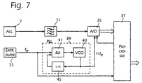
- the corresponding signal processing as performed in a digital way is illustrated in the block diagram of Fig. 6.
- the signal from the accelerometer 7, which is pre-filtered by the filter 11, is fed to an A/D-converter 35.
- the A/D-converter is controlled by means of a suitable pulse signal which is obtained from a pulse signal representing the frequency of the excitation and in this case is shown as obtained from a pulse sensor 33, e.g. located to directly sense the rotation of the eccentric body.
- the pulse sensor can be arranged on the bearing plate 9 to sense each passage of some mechanical unevenness or some electric or magnetic inhomogeneity of the shaft of the eccentric.
- the signal of the accelerometer must be sampled by the A/D-convertor 35 during a time period corresponding to two full turns of the rotation of the eccentric body, i.e. two periods of the excitation.
- the sampling frequency is in an advantageous way selected as a natural number multiplied by the excitation frequency where the natural number advantageously can be a power of 2.
- the digital signal obtained from the A/D-converter 35 is delivered to a signal processor 37 which performs a mathematic calculation of the Fourier-transform of the signal. Then the corresponding signals are obtained, i.e. the size of the DC-component, the amplitudes of the harmonic components having frequencies corresponding to half the excitation frequency, equal to the excitation frequency, corresponding to three times half the excitation frequency, etc. In particular, here the amplitudes are obtained for the harmonic components having frequencies corresponding to half the excitation frequency and to the excitation frequency and they are divided by each other to generate an output signal of the processor which is used in the control of the roller machine.
- the signal from the pulse sensor 33 can as above be fed to a phase-lock circuit 39.
- the signal representing the excitation frequency is fed to a phase detector 41.
- the output signal of the phase detector 41 is delivered to voltage control oscillator 43, the output signal of which is fed back to the phase detector 41 through a frequency-dividing circuit 45 producing pulses with a frequency corresponding to the oscillation frequency from the oscillator 43 divided by a natural number n and thus delivers its pulse signal back to the phase detector 41.
- the voltage controlled oscillator 43 will then produce an output signal of the pulse type having the desired frequency n ⁇ f e .
- the output signal of the oscillator will then also have a definite phase position in relation to the signal from the pulse sensor and then in relation to the signal representing the oscillation movement of the roller, which signal, however, the processor not necessarily has to use.
- the signal of the oscillator 43 is fed to the A/D-converter 35 for control of the sampling operation thereof.
Landscapes
- Engineering & Computer Science (AREA)
- Structural Engineering (AREA)
- Civil Engineering (AREA)
- Architecture (AREA)
- Life Sciences & Earth Sciences (AREA)
- General Life Sciences & Earth Sciences (AREA)
- Environmental & Geological Engineering (AREA)
- Soil Sciences (AREA)
- Agronomy & Crop Science (AREA)
- Mining & Mineral Resources (AREA)
- Paleontology (AREA)
- General Engineering & Computer Science (AREA)
- Road Paving Machines (AREA)
- Vehicle Body Suspensions (AREA)
- Apparatuses For Generation Of Mechanical Vibrations (AREA)
- Vibration Prevention Devices (AREA)
- General Electrical Machinery Utilizing Piezoelectricity, Electrostriction Or Magnetostriction (AREA)
- Piezo-Electric Or Mechanical Vibrators, Or Delay Or Filter Circuits (AREA)
Abstract
Description
Claims (14)
- A method for controlling a body, in particular a roller in a roller machine for compacting material, the body being excited to give the body an oscillation movement, the excitation being periodic and having a frequency, characterized by controlling the excitation, so that the resulting oscillating frequency of the vibrating body contains a predetermined, generally a small, proportion of a harmonic oscillation having a frequency corresponding to half the frequency with which the vibrating body is excited.
- A method according to claim 1, characterized in that in the control of the excitation only the resulting oscillation movement is considered in a plane which is vertical or is substantially vertical, in particular deviating from a vertical position by at most 30°.
- A method according to one of claims 1 - 2, characterized in that in the control of the excitation, the body is excited so that its resulting oscillation movement at different excitation degrees will have substantially different amplitudes.
- A method according to one of claims 1 - 2, characterized in that in the control of the excitation, the body is excited so that its resulting oscillation movement at different excitation degrees will have substantially different frequencies.
- A method according to one of claims 1 - 4, characterized by measuring the oscillation movement of the vibrating body by means of a sensor in substantially vertical direction or in a direction which deviates from the vertical direction by at most 30°.
- A method according to one of claims 1 - 5, characterized by measuring the oscillation movement of the vibrating body by means of an accelerometer which is attached to the body or to a part in which the body is rotationally mounted.
- A method according to one of claims 5 - 6, characterized in that the measured values, as a function of the time, are harmonically analyzed to determine the amplitude of both a principal oscillation having half the excitation frequency, and the excitation oscillation having the excitation frequency, and that these amplitudes are compared for the control of the excitation so that the amplitude of the oscillation having half the excitation frequency always corresponds to a predetermined proportion of the amplitude of the oscillation having the excitation frequency.
- A device for control of a body, in particular a roller in a roller machine for compacting a material located underneath the body, the body being arranged to be excited by excitation means to give the body an oscillation movement, the excitation being periodic and having a frequency, characterized by means for controlling and adjusting the excitation means so that the resulting oscillating movement of the vibrating body contains a predetermined, generally a small, proportion of a harmonic oscillation having a frequency corresponding to half the frequency with which the vibrating body is excited.
- A device according to claim 8, characterized in that the means for controlling and adjusting the excitation are arranged to only consider the resulting oscillation movement of the body in a plane which is vertical or is substantially vertical, in particular deviating from the vertical position by at most 30°.
- A device according to one of claims 8 - 9, characterized by a sensor for measuring the oscillation movement of the vibrating body.
- A device according to claim 10, characterized in that the sensor is mounted for a determination of the acceleration of the body in a substantially vertical direction, or in a direction which deviates from a vertical direction by at most 30°.
- A device according to one of claims 10 - 11, characterized in that the sensor is attached to the body, or to a part in which the body is rotatably mounted.
- A device according to one of claims 10 - 12, characterized in that the sensor is an accelerometer.
- A device according to one of claims 10 - 13, characterized by calculation means for analysing harmonically the registered values of the oscillation movement, as a function of time, in order to determine the amplitude of both an oscillation having half the excitation frequency and the oscillation having the excitation frequency, the means for controlling and adjusting being arranged to compare these amplitudes in the control and the adjustment of the excitation means so that the amplitude of the oscillation having half the excitation frequency always corresponds to predetermined a proportion of the amplitude of the oscillation having the excitation frequency.
Applications Claiming Priority (3)
| Application Number | Priority Date | Filing Date | Title |
|---|---|---|---|
| SE9300776A SE501040C2 (en) | 1993-03-08 | 1993-03-08 | Method and apparatus for controlling the vibration movement of a roller when packing a support such as soil, road banks, asphalt, etc. |
| SE9300776 | 1993-03-08 | ||
| PCT/SE1994/000195 WO1994020684A1 (en) | 1993-03-08 | 1994-03-08 | Control of a compacting machine |
Publications (2)
| Publication Number | Publication Date |
|---|---|
| EP0688379A1 EP0688379A1 (en) | 1995-12-27 |
| EP0688379B1 true EP0688379B1 (en) | 1998-10-21 |
Family
ID=20389160
Family Applications (1)
| Application Number | Title | Priority Date | Filing Date |
|---|---|---|---|
| EP94909399A Expired - Lifetime EP0688379B1 (en) | 1993-03-08 | 1994-03-08 | Control of a compacting machine |
Country Status (6)
| Country | Link |
|---|---|
| US (1) | US5695298A (en) |
| EP (1) | EP0688379B1 (en) |
| AT (1) | ATE172552T1 (en) |
| DE (1) | DE69414099T2 (en) |
| SE (1) | SE501040C2 (en) |
| WO (1) | WO1994020684A1 (en) |
Cited By (1)
| Publication number | Priority date | Publication date | Assignee | Title |
|---|---|---|---|---|
| DE102007018743A1 (en) | 2007-04-22 | 2008-10-23 | Bomag Gmbh | Method and system for controlling compaction machines |
Families Citing this family (30)
| Publication number | Priority date | Publication date | Assignee | Title |
|---|---|---|---|---|
| DE4434779A1 (en) * | 1994-09-29 | 1996-04-04 | Bomag Gmbh | Method and device for dynamically compacting soil |
| WO1998017865A1 (en) * | 1996-10-21 | 1998-04-30 | Ammann Verdichtung Ag | Method of measuring mechanical data of a soil, and of compacting the soil, and measuring or soil-compaction device |
| FR2772805B1 (en) * | 1997-12-24 | 2000-02-25 | Procedes Tech Const | DEVICE FOR CONTROLLING THE AMPLITUDE OF THE VIBRATIONS OF A VARIABLE MOMENT |
| US6188942B1 (en) | 1999-06-04 | 2001-02-13 | Caterpillar Inc. | Method and apparatus for determining the performance of a compaction machine based on energy transfer |
| DE10019806B4 (en) * | 2000-04-20 | 2005-10-20 | Wacker Construction Equipment | Soil compacting device with vibration detection |
| DE10028949A1 (en) * | 2000-06-16 | 2002-03-07 | Bomag Gmbh | Method and device for determining the degree of compaction in soil compaction |
| DE10053446B4 (en) * | 2000-10-27 | 2006-03-02 | Wacker Construction Equipment Ag | Steerable vibration plate and mobile vibrating plate system |
| US6558072B2 (en) | 2001-05-15 | 2003-05-06 | Caterpillar Paving Products Inc. | Speed control system for a work machine |
| US20030026657A1 (en) * | 2001-06-06 | 2003-02-06 | Ingersoll-Rand Company | Apparatus and method for controlling the start up and phase relationship between eccentric assemblies |
| JP4669173B2 (en) * | 2001-09-05 | 2011-04-13 | 酒井重工業株式会社 | Compaction degree management device in vibration type compaction vehicle |
| US7089823B2 (en) * | 2002-05-29 | 2006-08-15 | Caterpillar Paving Products Inc. | Vibratory mechanism controller |
| EP1411173A3 (en) * | 2002-10-15 | 2005-01-05 | Rammax Maschinenbau GmbH | Soil compacting device |
| DE602004029981D1 (en) * | 2003-01-24 | 2010-12-23 | Volvo Constr Equip Ab | SWING SYSTEM FOR COMPRESSED VEHICLES |
| EP1516961B1 (en) | 2003-09-19 | 2013-12-25 | Ammann Aufbereitung AG | Method for determining soil rigidity and soil compaction device |
| US7168885B2 (en) * | 2004-08-16 | 2007-01-30 | Caterpillar Paving Products Inc | Control system and method for a vibratory mechanism |
| DE102005029432A1 (en) * | 2005-06-24 | 2006-12-28 | Wacker Construction Equipment Ag | Soil compacting device with automatic or operator-intuitive adjustment of advance vector comprises vibrating plate controlled so that the direction of action of force can be set in more than two locations or changed as wished |
| US7938595B2 (en) * | 2007-04-30 | 2011-05-10 | Caterpillar Paving Products Inc. | Surface compactor and method of operating a surface compactor |
| DE102011088567A1 (en) * | 2011-12-14 | 2013-06-20 | Hamm Ag | Device for detecting the movement of a compactor roller of a soil compactor |
| DE102013200274B4 (en) | 2013-01-10 | 2016-11-10 | Mts Maschinentechnik Schrode Ag | Method for operating a mounted compactor, as well as storage medium and mounted compactor |
| CN104343071B (en) * | 2013-08-01 | 2017-11-03 | 江苏骏马压路机械有限公司 | The road roller prior-warning device for preventing building from damaging |
| DE102014203585A1 (en) * | 2014-02-27 | 2015-08-27 | Hamm Ag | Method for determining a slip state of the compactor roller of a soil compactor caused by an oscillatory movement of a compactor roller |
| DE102016109888A1 (en) * | 2016-05-30 | 2017-11-30 | Hamm Ag | Soil compactor and method for operating a soil compactor |
| US10253461B2 (en) * | 2016-12-07 | 2019-04-09 | Wirtgen Gmbh | Variable width automatic transition |
| CN110446814B (en) * | 2017-03-21 | 2021-11-05 | 沃尔沃建筑设备公司 | Vibratory compactor and associated control system and method providing coordinated impact from first and second drums |
| CN107014577B (en) * | 2017-03-31 | 2019-04-19 | 共享装备股份有限公司 | A verification method for vibration compaction platform |
| CN107700324B (en) * | 2017-10-21 | 2019-11-05 | 王凯盛 | A desert road construction vehicle |
| US11592055B2 (en) | 2018-08-30 | 2023-02-28 | Lake Country Tool, Llc | Adjustable stroke device with cam |
| SE543161C2 (en) | 2018-09-28 | 2020-10-13 | Dynapac Compaction Equipment Ab | Method of controlling operation of a vibratory roller |
| CN116761917B (en) * | 2020-10-14 | 2026-04-28 | 沃尔沃建筑设备公司 | Amplitude setting detection for vibratory surface compactors |
| DE102022111975A1 (en) | 2022-05-12 | 2023-11-16 | Mts Schrode Ag | Method for determining a load on an excavator attachment and excavator |
Family Cites Families (9)
| Publication number | Priority date | Publication date | Assignee | Title |
|---|---|---|---|---|
| US3797954A (en) * | 1972-05-23 | 1974-03-19 | Tampo Mfg Co | Ground compacting apparatus |
| US4103554A (en) * | 1976-03-12 | 1978-08-01 | Thurner Heinz F | Method and a device for ascertaining the degree of compaction of a bed of material with a vibratory compacting device |
| FR2390546A1 (en) * | 1977-05-09 | 1978-12-08 | Albaret Sa | METHOD AND DEVICE FOR FREQUENCY ADJUSTMENT OF VIBRATIONS APPLIED TO A SOIL FOR A COMPACTION MACHINE, AND COMPACTION MACHINE EQUIPPED WITH SUCH A DEVICE |
| SE424455B (en) * | 1980-11-26 | 1982-07-19 | Thurner Geodynamik Ab | PROCEDURE AND DEVICE FOR SEATING THE PACKING DEGREE OPENED BY PACKING A SUBSTRATE WITH A PACKAGING TOOL |
| SE432792B (en) * | 1982-04-01 | 1984-04-16 | Dynapac Maskin Ab | PROCEDURE AND DEVICE FOR ACHIEVING OPTIMAL PACKAGING DEVICE WHEN PACKING DIFFERENT MATERIALS LIKE ASPHALT, EARTH ETC Means a vibrating roller |
| DE3421824C2 (en) * | 1984-06-13 | 1986-07-17 | CASE VIBROMAX GmbH & Co KG, 4000 Düsseldorf | Device for checking the compaction in vibration compaction equipment |
| SE445566B (en) * | 1984-11-19 | 1986-06-30 | Thurner Geodynamik Ab | PROCEDURE FOR ESTIMATING THE PACKING RATE OPENED BY PACKAGING AND DEVICE TO META PACKING RATE FOR THE IMPLEMENTATION OF THE PROCEDURE |
| EP0459062B1 (en) * | 1990-05-28 | 1993-09-22 | Caterpillar Paving Products Inc. | Apparatus and method for controlling a vibratory tool |
| ES2045844T3 (en) * | 1990-05-28 | 1994-01-16 | Caterpillar Paving Prod | APPARATUS AND METHOD FOR CONTROLLING THE FREQUENCY OF VIBRATION OF A RAMMER. |
-
1993
- 1993-03-08 SE SE9300776A patent/SE501040C2/en not_active IP Right Cessation
-
1994
- 1994-03-08 EP EP94909399A patent/EP0688379B1/en not_active Expired - Lifetime
- 1994-03-08 WO PCT/SE1994/000195 patent/WO1994020684A1/en not_active Ceased
- 1994-03-08 DE DE69414099T patent/DE69414099T2/en not_active Expired - Fee Related
- 1994-03-08 US US08/522,259 patent/US5695298A/en not_active Expired - Lifetime
- 1994-03-08 AT AT94909399T patent/ATE172552T1/en not_active IP Right Cessation
Cited By (3)
| Publication number | Priority date | Publication date | Assignee | Title |
|---|---|---|---|---|
| DE102007018743A1 (en) | 2007-04-22 | 2008-10-23 | Bomag Gmbh | Method and system for controlling compaction machines |
| EP1985760A1 (en) | 2007-04-22 | 2008-10-29 | Bomag Gmbh | Method and system for controlling compacting machines |
| US8332105B2 (en) | 2007-04-22 | 2012-12-11 | Bomag Gmbh | Method and system for controlling compaction machines |
Also Published As
| Publication number | Publication date |
|---|---|
| SE9300776D0 (en) | 1993-03-08 |
| DE69414099D1 (en) | 1998-11-26 |
| SE9300776L (en) | 1994-09-09 |
| SE501040C2 (en) | 1994-10-24 |
| US5695298A (en) | 1997-12-09 |
| EP0688379A1 (en) | 1995-12-27 |
| ATE172552T1 (en) | 1998-11-15 |
| DE69414099T2 (en) | 1999-06-10 |
| WO1994020684A1 (en) | 1994-09-15 |
Similar Documents
| Publication | Publication Date | Title |
|---|---|---|
| US5695298A (en) | Control of a compacting machine | |
| JP3647865B2 (en) | Control method and control apparatus for consolidation of ground material | |
| US4127351A (en) | Dynamic soil compaction | |
| CA1205547A (en) | Procedure for optimation of the vibration amplitude in vibratory rollers | |
| EP0459063B1 (en) | Apparatus and method for controlling the frequency of vibration of a compacting machine | |
| CA2624328C (en) | Shale shaker | |
| US5164641A (en) | Apparatus and method for controlling the frequency of vibration of a compacting machine | |
| US6431790B1 (en) | Method of measuring mechanical data of a soil, and of compacting the soil, and measuring or soil-compaction device | |
| US4467652A (en) | Procedure and device for compaction measurement | |
| US10385530B1 (en) | Method for compaction detection and control when compacting a soil with a deep vibrator | |
| AU663255B2 (en) | Cone-type vibrating crusher and method for adjusting operation of such crusher | |
| GB1224123A (en) | Improvements in or relating to vibratory machines | |
| CN100534635C (en) | Oscillation sieving machine and operation method thereof | |
| US4579697A (en) | Method for packing concrete cement utilizing a vibrator | |
| US5983752A (en) | Adjustable counterweight system for a machine for forming concrete blocks, pavers or the like | |
| WO2001013072A3 (en) | Method and apparatus for coriolis flowmeter having an accuracy enhancing balance bar | |
| CN115179394A (en) | Cement stabilization solid waste aggregate base layer vibration compaction forming equipment | |
| DE10351177B4 (en) | Method and device for a three-dimensional vibration system for casting containers in the lost-foam casting process | |
| JPH0129617B2 (en) | ||
| SU1099216A1 (en) | Method of rotor balancing | |
| US6568457B2 (en) | Vibrating apparatus for compacting molding sand | |
| RU2717494C1 (en) | Vibratory jaw crusher | |
| SU779073A1 (en) | Vibrated platform | |
| JPS6329231A (en) | Measuring instrument for tamping degree of tamping device for base ground | |
| SU1194023A1 (en) | Method of vibration stabilization of workpiece dimensions |
Legal Events
| Date | Code | Title | Description |
|---|---|---|---|
| PUAI | Public reference made under article 153(3) epc to a published international application that has entered the european phase |
Free format text: ORIGINAL CODE: 0009012 |
|
| 17P | Request for examination filed |
Effective date: 19950911 |
|
| AK | Designated contracting states |
Kind code of ref document: A1 Designated state(s): AT CH DE ES FR GB IT LI |
|
| GRAG | Despatch of communication of intention to grant |
Free format text: ORIGINAL CODE: EPIDOS AGRA |
|
| 17Q | First examination report despatched |
Effective date: 19971216 |
|
| RAP1 | Party data changed (applicant data changed or rights of an application transferred) |
Owner name: GEODYNAMIK HT AKTIEBOLAG |
|
| GRAG | Despatch of communication of intention to grant |
Free format text: ORIGINAL CODE: EPIDOS AGRA |
|
| GRAH | Despatch of communication of intention to grant a patent |
Free format text: ORIGINAL CODE: EPIDOS IGRA |
|
| GRAH | Despatch of communication of intention to grant a patent |
Free format text: ORIGINAL CODE: EPIDOS IGRA |
|
| GRAA | (expected) grant |
Free format text: ORIGINAL CODE: 0009210 |
|
| AK | Designated contracting states |
Kind code of ref document: B1 Designated state(s): AT CH DE ES FR GB IT LI |
|
| PG25 | Lapsed in a contracting state [announced via postgrant information from national office to epo] |
Ref country code: LI Free format text: LAPSE BECAUSE OF FAILURE TO SUBMIT A TRANSLATION OF THE DESCRIPTION OR TO PAY THE FEE WITHIN THE PRESCRIBED TIME-LIMIT Effective date: 19981021 Ref country code: IT Free format text: LAPSE BECAUSE OF FAILURE TO SUBMIT A TRANSLATION OF THE DESCRIPTION OR TO PAY THE FEE WITHIN THE PRE;WARNING: LAPSES OF ITALIAN PATENTS WITH EFFECTIVE DATE BEFORE 2007 MAY HAVE OCCURRED AT ANY TIME BEFORE 2007. THE CORRECT EFFECTIVE DATE MAY BE DIFFERENT FROM THE ONE RECORDED.SCRIBED TIME-LIMIT Effective date: 19981021 Ref country code: FR Free format text: LAPSE BECAUSE OF FAILURE TO SUBMIT A TRANSLATION OF THE DESCRIPTION OR TO PAY THE FEE WITHIN THE PRESCRIBED TIME-LIMIT Effective date: 19981021 Ref country code: ES Free format text: THE PATENT HAS BEEN ANNULLED BY A DECISION OF A NATIONAL AUTHORITY Effective date: 19981021 Ref country code: CH Free format text: LAPSE BECAUSE OF FAILURE TO SUBMIT A TRANSLATION OF THE DESCRIPTION OR TO PAY THE FEE WITHIN THE PRESCRIBED TIME-LIMIT Effective date: 19981021 Ref country code: AT Free format text: LAPSE BECAUSE OF FAILURE TO SUBMIT A TRANSLATION OF THE DESCRIPTION OR TO PAY THE FEE WITHIN THE PRESCRIBED TIME-LIMIT Effective date: 19981021 |
|
| REF | Corresponds to: |
Ref document number: 172552 Country of ref document: AT Date of ref document: 19981115 Kind code of ref document: T |
|
| REG | Reference to a national code |
Ref country code: CH Ref legal event code: EP |
|
| REF | Corresponds to: |
Ref document number: 69414099 Country of ref document: DE Date of ref document: 19981126 |
|
| PG25 | Lapsed in a contracting state [announced via postgrant information from national office to epo] |
Ref country code: GB Free format text: LAPSE BECAUSE OF NON-PAYMENT OF DUE FEES Effective date: 19990308 |
|
| EN | Fr: translation not filed | ||
| REG | Reference to a national code |
Ref country code: CH Ref legal event code: PL |
|
| PLBE | No opposition filed within time limit |
Free format text: ORIGINAL CODE: 0009261 |
|
| STAA | Information on the status of an ep patent application or granted ep patent |
Free format text: STATUS: NO OPPOSITION FILED WITHIN TIME LIMIT |
|
| 26N | No opposition filed | ||
| GBPC | Gb: european patent ceased through non-payment of renewal fee |
Effective date: 19990308 |
|
| PGFP | Annual fee paid to national office [announced via postgrant information from national office to epo] |
Ref country code: DE Payment date: 20090324 Year of fee payment: 16 |
|
| PG25 | Lapsed in a contracting state [announced via postgrant information from national office to epo] |
Ref country code: DE Free format text: LAPSE BECAUSE OF NON-PAYMENT OF DUE FEES Effective date: 20101001 |