EP0688001A1 - Apparatus for storing and delivering sale units - Google Patents
Apparatus for storing and delivering sale units Download PDFInfo
- Publication number
- EP0688001A1 EP0688001A1 EP95107889A EP95107889A EP0688001A1 EP 0688001 A1 EP0688001 A1 EP 0688001A1 EP 95107889 A EP95107889 A EP 95107889A EP 95107889 A EP95107889 A EP 95107889A EP 0688001 A1 EP0688001 A1 EP 0688001A1
- Authority
- EP
- European Patent Office
- Prior art keywords
- compartments
- door
- delivery
- delivery unit
- unit
- Prior art date
- Legal status (The legal status is an assumption and is not a legal conclusion. Google has not performed a legal analysis and makes no representation as to the accuracy of the status listed.)
- Granted
Links
Images

Classifications
-
- G—PHYSICS
- G07—CHECKING-DEVICES
- G07F—COIN-FREED OR LIKE APPARATUS
- G07F5/00—Coin-actuated mechanisms; Interlocks
- G07F5/18—Coin-actuated mechanisms; Interlocks specially adapted for controlling several coin-freed apparatus from one place
-
- G—PHYSICS
- G07—CHECKING-DEVICES
- G07F—COIN-FREED OR LIKE APPARATUS
- G07F11/00—Coin-freed apparatus for dispensing, or the like, discrete articles
- G07F11/02—Coin-freed apparatus for dispensing, or the like, discrete articles from non-movable magazines
- G07F11/04—Coin-freed apparatus for dispensing, or the like, discrete articles from non-movable magazines in which magazines the articles are stored one vertically above the other
- G07F11/16—Delivery means
- G07F11/163—Delivery means characterised by blocking access to the output bins
-
- G—PHYSICS
- G07—CHECKING-DEVICES
- G07F—COIN-FREED OR LIKE APPARATUS
- G07F11/00—Coin-freed apparatus for dispensing, or the like, discrete articles
- G07F11/46—Coin-freed apparatus for dispensing, or the like, discrete articles from movable storage containers or supports
- G07F11/58—Coin-freed apparatus for dispensing, or the like, discrete articles from movable storage containers or supports the articles being supported on or by endless belts or like conveyors
-
- G—PHYSICS
- G07—CHECKING-DEVICES
- G07F—COIN-FREED OR LIKE APPARATUS
- G07F11/00—Coin-freed apparatus for dispensing, or the like, discrete articles
- G07F11/62—Coin-freed apparatus for dispensing, or the like, discrete articles in which the articles are stored in compartments in fixed receptacles
-
- G—PHYSICS
- G07—CHECKING-DEVICES
- G07F—COIN-FREED OR LIKE APPARATUS
- G07F5/00—Coin-actuated mechanisms; Interlocks
- G07F5/26—Interlocks, e.g. for locking the doors of compartments other than that to be used
-
- G—PHYSICS
- G07—CHECKING-DEVICES
- G07F—COIN-FREED OR LIKE APPARATUS
- G07F9/00—Details other than those peculiar to special kinds or types of apparatus
- G07F9/002—Vending machines being part of a centrally controlled network of vending machines
Definitions
- EP 0 490 205 A2 discloses an apparatus as defined in the generic part of claim 1.
- the compartments containing the articles are movable by a circulatory lift manner.
- An object of the invention is to improve the apparatus of EP 0 490 205 A2 in order to further simplify construction and use and to reduce the space needed to install the apparatus.
- the construction of the apparatus with fixed compartments is easy.
- the mechanism to move the delivery unit along a row of compartments is easy to construct and to use because the weight to be moved is lower. All articles can be made visible at the same time by preferably using a transparent roller-shutter-like cover.
- the apparatus contains a plurality of storage units which can be e.g. positioned side-by-side and coupled to each other only by power and/or data connections.
- the apparatus can easily be adapted to different needs.
- the delivery unit can contain the sale units, e.g., screw boxes, and by means of the long-range transmission means it is possible to monitor the removal and stock from a remote control room or exchange. This leads to a significant simplification relative to stock control and the reloading of the delivery unit.
- the existing stock can be adapted in an optimum manner to the needs of a particular delivery unit by the control room, and consequently, waiting and procurement times are avoided.
- an apparatus 11 for storing and delivering articles includes several storage units 50, 51 and 52, each in the form of a cabinet, and a control unit 53 of matching construction.
- the units 50 to 53 are in the form of upright standing cabinets or shelves with a housing (80) each, the fronts of which are somewhat inclined relative to the backs thereof.
- the units 50 to 53 are positioned juxtaposed to each other. They are interconnected by electrical wiring for providing power to drives, locks, etc., and for controlling the same.
- the storage units 50 to 52 contain a plurality of juxtaposed compartments 16, forming the compartment rows 17. As shown in FIG. 2, the bottoms 54 of the compartments are relative to the inclined front face of the units, inclined slightly downwardly in order to urge articles 35 stored in the compartments away from the front of the bottoms 54, i.e., in a direction to prevent the articles 35 from falling out.
- the compartments 16 are fixed in the units 50 to 52 for storing articles 35.
- the storage units 50, 51 and 52 are preferably of different widths though they are of equal height.
- the compartments therein are different in size and number, but equal in each unit. So, for example, storage unit 50 has a large number of smaller compartments arranged in ten compartment rows, while unit 51, which is not as wide as unit 50, has ten rows of only two compartments in each row, and unit 52 has two relatively high compartments in a row and, therefore, only three or four rows of compartments.
- each unit 50 to 52 there is a guide 55 of U-shape with a substantially vertically-extending guide groove 56.
- a delivery unit 57 is movable vertically in order to be aligned with each compartment row 17.
- Each delivery unit contains a front panel 58 in which delivery doors 13 are hinged to be pivotable about a lower horizontal axis as shown in FIG. 2.
- Each delivery unit 57 includes a plurality of doors equal to the number of compartments in each compartment row 17 of the unit 57, each of which can be individually opened.
- the delivery unit 57 includes handles 59 extending therefrom for moving the unit 57, and include a trigger 60 which can be pressed by the operator in order to trigger the release of a lock 66 of the delivery unit 57.
- a cover 61 constructed like a roller-shutter.
- the elements of this cover contain transparent strips 62, e.g., made of Plexiglas material or another transparent material, and non-transparent strips 63, e.g., aluminum profiles, having an upper and lower groove for receiving the edges of the transparent strips 63 therein.
- Transparent and non-transparent strips 62 and 63 are arranged in the cover in alternating sequence. They are sized to match the height of the rows. So, for example, in the units 50 and 51, one pair of transparent and non-transparent strips 62 and 63 cover the height of one compartment row. Accordingly, each compartment row is visible through its corresponding transparent strip 62.
- the strips 62 and 63 are mounted on a chain or ribbon in the area of the guides 55, and are pivotable relative to each other such that the cover 61 can be guided around deflection wheels 64 which are rotatable around a horizontal axis and are situated behind the upper and lower front panel parts 65 of each unit 50-52.
- Each cover 61 is movable separately from the cover 61 of an adjacent unit.
- Each cover 61 which is of roller-shutter type construction, is connected to itself on the backside of its corresponding storage unit 50-52 by flexible means, e.g., rubber ribbons, strips or bands, in order to provide tension to the cover.
- Each delivery unit 57 includes a unit locking mechanism 66, and for each door 13, a door locking and releasing mechanism 67.
- the locking mechanisms 66 and 67 are electrically actuable, and controlled by an electronic control unit 68, which is in turn controlled by a central control 69, e.g., a computer, of a control unit 53.
- the delivery unit 57 contains a sensor 70 which cooperates with coding strips 71 which extend along the lateral sides of each storage unit 50-52 beneath the guides 55.
- the sensor 70 for example, is an active optical sensor for reading the coding strips 71, for producing a signal for identifying the compartment row with which the delivery unit is aligned.
- the delivery unit 57 also has a direction indicator 72, similar to direction indicators for elevators, for showing in which direction the delivery unit 57 has to be moved in order to be aligned with a row in which a desired compartment is situated.
- the delivery unit 57 also includes indicators 73, e.g., lamps, for each door for indicating whether the compartment aligned to the door is holding an article 35 or not.
- indicators 73 e.g., lamps
- the control unit 53 has a display 74, e.g., a computer monitor, the computer 69, a keyboard 75, a printer 76 and a shelf for catalogs 77 or like articles.
- the user identifies the article visually through the transparent cover 61.
- the delivery unit 57 is then directed to the compartment row 17 containing the article by gripping the handles 59, and pressing the trigger 60.
- the trigger 60 does not directly release the delivery unit lock 66, but this is done electrically only if the computer 69 is switched on and is enabled to follow and store information relating to the actions requested by, for example, pressing the trigger 60.
- the door indicator 73 indicates whether the compartment is validly filled. In a simple mode of operation, the user can now open the desired compartment wanted and take out the requested or desired article. This is then registered and stored in the computer.
- the display 74 indicates the content and status of all compartments passed by the delivery unit.
- the user can select a desired article by its identification number or name, or other code through the keyboard 75.
- the display shows immediately whether the article is available, and in which of the units 50 to 52 it is located.
- the direction indicator 72 of the respective unit shows in which direction the delivery unit must be moved in order to approach the row with the article wanted.
- the door indicator indicates which door is to be opened.
- the respective door is released by the doorlock 67, and the door can then be opened.
- There is a timing means included in the electronics which, if the door is not opened within a predetermined time limit, causes the door to be locked again. This permits canceling of an undesired, but mistakenly entered, operation.
- Each action is stored in the memory of the computer 69, and the printer 76 prints out a receipt protocol for each delivery operation after the door 13 is again closed.
- the computer 69 also contains memory, e.g., in the form of a disk drive, for storing all operations performed, and sends out automatically at a predetermined time, e.g., at night time when economical tariff of the telephone or other data lines is available, a report to the central station for debiting and reloading purposes via a long-range data transmission means 26, described later with reference to Fig. 3.
- the control unit 69 also enables the user to order articles directly which are not contained in the apparatus by using the catalog 77. The ordered articles can then be delivered with the next refilling of the apparatus, and the computer 69 can provide information that articles ordered in this way should be available in the apparatus in the future.
- the same procedure can be used as for taking out the articles, namely, typing in the appropriate number, positioning the delivery unit, and opening the door. Through a special code entered the computer can note that this is a refilling operation. It is, however, also possible to open the front panel of the delivery unit for repair or other operations.
- the subcontrol station 68 for each separate unit is situated in this area, and is easily accessible. The station 68 controls all functions of the door and delivery unit release mechanisms, the sensing of the positions through sensor 70, etc., and only provides the results to the control unit 53.
- the described embodiment is, due to the fact that the compartments are stationary, very economical if the number of compartments are not too large within a given space. It is variable in the size of compartments due to the fact that different storage units can be aligned and combined into a complete apparatus by simply putting them adjacent to each other, and connecting them by electrical connections with the central control unit 53.
- the long-range transmission means 26 is diagrammatically shown in FIG. 3.
- Several delivery units 11 may be connected by means of a remote control unit 25 to a TEMEX network connection 28, from where they are passed via the normal telephone network 29, a TEMEX exchange 30 and optionally a main TEMEX exchange 31 to the TEMEX routing desk 32 of a supplier through which they are fed into the supplier's data processing unit 33.
- the signals follow the same route on the return path.
- the postal TEMEX system transmits data in a correspondingly coded form via the telephone network.
- the information can also be transmitted by fax or by dialing modems.
- several delivery units 11 can be connected to one remote control unit.
Abstract
Description
- EP 0 490 205 A2 discloses an apparatus as defined in the generic part of
claim 1. In the embodiment shown there, the compartments containing the articles are movable by a circulatory lift manner. - An object of the invention is to improve the apparatus of EP 0 490 205 A2 in order to further simplify construction and use and to reduce the space needed to install the apparatus.
- The object is achieved by the features of
claim 1. - By using fixed compartments, the following advantages are achieved:
- The construction of the apparatus with fixed compartments is easy. The mechanism to move the delivery unit along a row of compartments is easy to construct and to use because the weight to be moved is lower. All articles can be made visible at the same time by preferably using a transparent roller-shutter-like cover.
- In a preferred embodiment, the apparatus contains a plurality of storage units which can be e.g. positioned side-by-side and coupled to each other only by power and/or data connections. By such modular construction, the apparatus can easily be adapted to different needs.
- The delivery unit can contain the sale units, e.g., screw boxes, and by means of the long-range transmission means it is possible to monitor the removal and stock from a remote control room or exchange. This leads to a significant simplification relative to stock control and the reloading of the delivery unit. The existing stock can be adapted in an optimum manner to the needs of a particular delivery unit by the control room, and consequently, waiting and procurement times are avoided.
- Further features and advantages disclosed in EP 0 490 205 A2 the disclosure of which is herein included by reference are also present in this invention.
- These and further features of the invention can be gathered from the claims, whose wording by reference is made into the content of the description, as well as from the description and drawings, the individual features being realizable either alone or in the form of sub-combinations in an embodiment of the invention and in other fields and can represent advantageous, independently protectable constructions for which protection is hereby claimed. Preferred embodiments of the invention are described hereinafter relative to the drawings, wherein:
- FIG. 1
- is a perspective view of a preferred embodiment of the delivery unit.
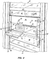
- Fig. 2
- is a detailed view of the embodiment of Fig. 1.
- Fig. 3
- is a block circuit diagram of several delivery units connected by means of a data network to a data processing central unit.
- As shown in detail by FIG. 1, an
apparatus 11 for storing and delivering articles includesseveral storage units control unit 53 of matching construction. Theunits 50 to 53 are in the form of upright standing cabinets or shelves with a housing (80) each, the fronts of which are somewhat inclined relative to the backs thereof. Theunits 50 to 53 are positioned juxtaposed to each other. They are interconnected by electrical wiring for providing power to drives, locks, etc., and for controlling the same. - The
storage units 50 to 52 contain a plurality of juxtaposedcompartments 16, forming thecompartment rows 17. As shown in FIG. 2, the bottoms 54 of the compartments are relative to the inclined front face of the units, inclined slightly downwardly in order to urgearticles 35 stored in the compartments away from the front of the bottoms 54, i.e., in a direction to prevent thearticles 35 from falling out. - The
compartments 16 are fixed in theunits 50 to 52 for storingarticles 35. - The
storage units storage unit 50 has a large number of smaller compartments arranged in ten compartment rows, whileunit 51, which is not as wide asunit 50, has ten rows of only two compartments in each row, andunit 52 has two relatively high compartments in a row and, therefore, only three or four rows of compartments. - At the lateral side of each
unit 50 to 52 there is aguide 55 of U-shape with a substantially vertically-extendingguide groove 56. In the guide 55 adelivery unit 57 is movable vertically in order to be aligned with eachcompartment row 17. Each delivery unit contains afront panel 58 in whichdelivery doors 13 are hinged to be pivotable about a lower horizontal axis as shown in FIG. 2. - Each
delivery unit 57 includes a plurality of doors equal to the number of compartments in eachcompartment row 17 of theunit 57, each of which can be individually opened. - The
delivery unit 57 includeshandles 59 extending therefrom for moving theunit 57, and include atrigger 60 which can be pressed by the operator in order to trigger the release of alock 66 of thedelivery unit 57. - Connected to the upper and lower rim of the delivery unit is a
cover 61 constructed like a roller-shutter. The elements of this cover containtransparent strips 62, e.g., made of Plexiglas material or another transparent material, andnon-transparent strips 63, e.g., aluminum profiles, having an upper and lower groove for receiving the edges of thetransparent strips 63 therein. Transparent andnon-transparent strips units non-transparent strips transparent strip 62. - The
strips guides 55, and are pivotable relative to each other such that thecover 61 can be guided arounddeflection wheels 64 which are rotatable around a horizontal axis and are situated behind the upper and lowerfront panel parts 65 of each unit 50-52. Eachcover 61 is movable separately from thecover 61 of an adjacent unit. Eachcover 61, which is of roller-shutter type construction, is connected to itself on the backside of its corresponding storage unit 50-52 by flexible means, e.g., rubber ribbons, strips or bands, in order to provide tension to the cover. - Each
delivery unit 57 includes aunit locking mechanism 66, and for eachdoor 13, a door locking and releasing mechanism 67. Thelocking mechanisms 66 and 67 are electrically actuable, and controlled by anelectronic control unit 68, which is in turn controlled by acentral control 69, e.g., a computer, of acontrol unit 53. Thedelivery unit 57 contains a sensor 70 which cooperates with coding strips 71 which extend along the lateral sides of each storage unit 50-52 beneath theguides 55. The sensor 70, for example, is an active optical sensor for reading the coding strips 71, for producing a signal for identifying the compartment row with which the delivery unit is aligned. - The
delivery unit 57 also has adirection indicator 72, similar to direction indicators for elevators, for showing in which direction thedelivery unit 57 has to be moved in order to be aligned with a row in which a desired compartment is situated. - The
delivery unit 57 also includesindicators 73, e.g., lamps, for each door for indicating whether the compartment aligned to the door is holding anarticle 35 or not. - The
control unit 53 has adisplay 74, e.g., a computer monitor, thecomputer 69, akeyboard 75, aprinter 76 and a shelf forcatalogs 77 or like articles. - In order to obtain a specific article, the user identifies the article visually through the
transparent cover 61. Thedelivery unit 57 is then directed to thecompartment row 17 containing the article by gripping thehandles 59, and pressing thetrigger 60. Thetrigger 60 does not directly release thedelivery unit lock 66, but this is done electrically only if thecomputer 69 is switched on and is enabled to follow and store information relating to the actions requested by, for example, pressing thetrigger 60. After aligning thedelivery unit 57 with the row containing the desired article, thedoor indicator 73 indicates whether the compartment is validly filled. In a simple mode of operation, the user can now open the desired compartment wanted and take out the requested or desired article. This is then registered and stored in the computer. - Simultaneously with the moving of
delivery unit 57, thedisplay 74 indicates the content and status of all compartments passed by the delivery unit. - In another mode of use, the user can select a desired article by its identification number or name, or other code through the
keyboard 75. The display shows immediately whether the article is available, and in which of theunits 50 to 52 it is located. Thedirection indicator 72 of the respective unit shows in which direction the delivery unit must be moved in order to approach the row with the article wanted. The door indicator indicates which door is to be opened. The respective door is released by the doorlock 67, and the door can then be opened. There is a timing means included in the electronics which, if the door is not opened within a predetermined time limit, causes the door to be locked again. This permits canceling of an undesired, but mistakenly entered, operation. - Each action is stored in the memory of the
computer 69, and theprinter 76 prints out a receipt protocol for each delivery operation after thedoor 13 is again closed. - The
computer 69 also contains memory, e.g., in the form of a disk drive, for storing all operations performed, and sends out automatically at a predetermined time, e.g., at night time when economical tariff of the telephone or other data lines is available, a report to the central station for debiting and reloading purposes via a long-range data transmission means 26, described later with reference to Fig. 3. Thecontrol unit 69 also enables the user to order articles directly which are not contained in the apparatus by using thecatalog 77. The ordered articles can then be delivered with the next refilling of the apparatus, and thecomputer 69 can provide information that articles ordered in this way should be available in the apparatus in the future. - For refilling purposes the same procedure can be used as for taking out the articles, namely, typing in the appropriate number, positioning the delivery unit, and opening the door. Through a special code entered the computer can note that this is a refilling operation. It is, however, also possible to open the front panel of the delivery unit for repair or other operations. The
subcontrol station 68 for each separate unit is situated in this area, and is easily accessible. Thestation 68 controls all functions of the door and delivery unit release mechanisms, the sensing of the positions through sensor 70, etc., and only provides the results to thecontrol unit 53. - The described embodiment is, due to the fact that the compartments are stationary, very economical if the number of compartments are not too large within a given space. It is variable in the size of compartments due to the fact that different storage units can be aligned and combined into a complete apparatus by simply putting them adjacent to each other, and connecting them by electrical connections with the
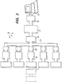
central control unit 53. - The long-range transmission means 26 is diagrammatically shown in FIG. 3.
Several delivery units 11 may be connected by means of aremote control unit 25 to aTEMEX network connection 28, from where they are passed via thenormal telephone network 29, aTEMEX exchange 30 and optionally amain TEMEX exchange 31 to theTEMEX routing desk 32 of a supplier through which they are fed into the supplier'sdata processing unit 33. The signals follow the same route on the return path. - The postal TEMEX system transmits data in a correspondingly coded form via the telephone network. In the same way, the information can also be transmitted by fax or by dialing modems. In addition,
several delivery units 11 can be connected to one remote control unit.
Claims (12)
- An apparatus for storing and delivering articles, especially sale units, comprising:a) storage means (50, 51, 52) comprising a plurality of compartments (16) for storing articles (35);
at least one delivery unit (57) having at least one delivery door (13) arranged on a front side of the delivery unit (57);b) positioning means for moving the at least one delivery door (13) relative to the compartments into a delivery position in which at least one of said compartments (16) is in alignment with the at least one delivery door (13);c) door release means (67) for the delivery door (13) for exposing a corresponding one of said compartments (16) located behind the door (13); andd) signal generating means (70) for generating signals representative of alignment of one of said compartments (16) with the delivery position and the release of the door (13),e) data processing means (69) for processing said signals and recording door releases and delivery position alignments of said delivery unit (57) and delivery door (13) relative to individual ones of said plurality of compartments (16),f) characterized in that the compartments (16) are arranged fixed in a housing (80), andg) the delivery unit (57) is movable relative to said housing (80). - The apparatus according to claim 1, characterized by long-range transmission means (26) for transmitting said signals to a data processing central unit (33) remote from the delivery unit (57).
- The apparatus according to claim 1 or 2, characterized in that the compartments (16) are juxtaposed with respect to each other in several article compartment rows (17), and said compartment rows (17) are arranged one on top of another, and that preferably the compartments (16) further comprise access openings arranged in a common, substantially vertically extending plane, the plane being preferably slightly inclined with respect to a strictly vertical plane and/or the compartments (16) have bottoms (54) which are downwardly inclined to a rear of the compartments (16) away from a front opening of each of said compartments (16).
- The apparatus according to anyone of the preceding claims, characterized in that the delivery unit (57) is movable in a vertical direction, and is connected to a movable cover (61) for covering the compartments (16).
- The apparatus according to claim 4, characterized in that the cover (61) is at least partially transparent and/or constructed in the form of a roller-shutter.
- The apparatus according to claim 4 or 5, characterized by guides (55, 56) located at two lateral sides of said housing (80) for guiding the delivery unit (57), preferably guiding between them transparent strips (62) and non-trans-parent strips (63) making up the cover (61), and arranged in alternating sequence, with the transparent strips (62) being wider than the non-trans-parent strips (63).
- The apparatus according to anyone of claims 4 to 6, characterized in that the cover (61) is guided at the upper and lower ends of said housing (80) by wheels (64) which are rotatable around horizontally extending axes.
- The apparatus according to anyone of the preceding claims, characterized in that the delivery unit (57) is movable manually after manual triggering of a delivery unit releasing mechanism (66), said releasing mechanism being releasable only if memory means, interconnected between the signal generating means (70) and the long-range transmission means (26), is in an operating status for enabling said release.
- The apparatus according to anyone of the preceding claims, characterized in that the signal generating means (70) comprises coding means (71) for cooperating with the delivery unit (57) for producing position signals representing the position of the delivery unit relative to each individual row (17) of the compartments (16), the coding means (71) comprising preferably optically readable code surfaces, and at least one optical sensor for reading said optically readable code surfaces.
- The apparatus according to anyone of the preceding claims, characterized by a plurality of storage units (50, 51, 52), each comprising several rows (17) of compartments (16) and a delivery unit (57), each storage unit (50, 51, 52) being of modular construction for being interconnected to other storage units electrically, wherein the apparatus preferably comprises at least one storage unit (50, 51, 52) and further comprises a separate control unit (53) having memory and, if present, a long-range transmission means (26), the control unit (53) being of modular construction for being electrically connected to the storage units (50, 51, 52), the control unit preferably comprising entry means (75) for entering data and a display (74).
- The apparatus according to anyone of the preceding claims, characterized in that the front (58) of the delivery unit (57) is openable for providing access to the door release means (67) and to an electronic control device comprising a part of the signal generating means (70).
- The apparatus according to anyone of the preceding claims, further comprising a display element (73) near each door (13) for indicating a full or empty condition of a compartment (16) which is aligned with the door (13), and/or a direction indicator (72) for indicating a direction in which the delivery unit (57) is to be moved to approach a desired compartment (16), in which an article (35) is contained, and which has been selected through use of entry means (75), and/or access duration control means for controlling the timing of release of the door (13).
Applications Claiming Priority (2)
| Application Number | Priority Date | Filing Date | Title |
|---|---|---|---|
| US08/259,242 US5438523A (en) | 1990-12-07 | 1994-06-13 | Apparatus for storing and delivering sale units |
| US259242 | 1999-02-26 |
Publications (2)
| Publication Number | Publication Date |
|---|---|
| EP0688001A1 true EP0688001A1 (en) | 1995-12-20 |
| EP0688001B1 EP0688001B1 (en) | 1998-03-04 |
Family
ID=22984153
Family Applications (1)
| Application Number | Title | Priority Date | Filing Date |
|---|---|---|---|
| EP95107889A Expired - Lifetime EP0688001B1 (en) | 1994-06-13 | 1995-05-24 | Apparatus for storing and delivering sale units |
Country Status (7)
| Country | Link |
|---|---|
| US (1) | US5438523A (en) |
| EP (1) | EP0688001B1 (en) |
| JP (1) | JPH08324724A (en) |
| AT (1) | ATE163787T1 (en) |
| DE (1) | DE69501685T2 (en) |
| DK (1) | DK0688001T3 (en) |
| ES (1) | ES2113694T3 (en) |
Cited By (1)
| Publication number | Priority date | Publication date | Assignee | Title |
|---|---|---|---|---|
| ES2116904A1 (en) * | 1996-02-15 | 1998-07-16 | Inelcom Ingenieria Electronica | System for monitoring the opening of doors, covers and the like. |
Families Citing this family (36)
| Publication number | Priority date | Publication date | Assignee | Title |
|---|---|---|---|---|
| US6000522A (en) * | 1995-06-12 | 1999-12-14 | Alice A Johnson | Multi-compartment and acceptors computerized vending machine |
| US6295482B1 (en) * | 1996-06-26 | 2001-09-25 | Sun Microsystems, Inc. | Electronic newspaper vending machine |
| EP0895200A1 (en) * | 1997-08-01 | 1999-02-03 | Gérard Peudepiece | Vending machine with electrical battery and remote management |
| US6163736A (en) * | 1998-06-19 | 2000-12-19 | Halfacre; Van | Tamper resistant programmable medicine dispenser |
| US6415202B1 (en) * | 1998-06-19 | 2002-07-02 | Van Halfacre | Tamper resistant programmable medicine dispenser |
| US6170929B1 (en) * | 1998-12-02 | 2001-01-09 | Ronald H. Wilson | Automated medication-dispensing cart |
| DE19927248C2 (en) * | 1999-06-15 | 2001-06-21 | Haenel & Co Altstaetten | Storage rack |
| US20030079129A1 (en) * | 1999-12-03 | 2003-04-24 | Lindsay Courtenay Traice Thomas | Secure delivery or collection system |
| US6223934B1 (en) | 2000-01-18 | 2001-05-01 | S&S X-Ray Products, Inc. | Scrub dispensing cabinet |
| WO2001065503A1 (en) * | 2000-03-03 | 2001-09-07 | Dock-1 Ag | Goods lock and method for the dispensing of objects |
| AU2001290661A1 (en) * | 2000-09-06 | 2002-03-22 | Advanced Pharmacy Technologies, L.L.C. | Automated prescription dispensing system and method of use |
| US20020087231A1 (en) * | 2001-01-04 | 2002-07-04 | Lewis Jimmy Randolph | Method and apparatus for filling stock orders |
| US6587748B2 (en) | 2001-08-20 | 2003-07-01 | B. John Baack | Automated parts dispensing system |
| US6847861B2 (en) * | 2001-11-30 | 2005-01-25 | Mckesson Automation, Inc. | Carousel product for use in integrated restocking and dispensing system |
| MXPA05001361A (en) * | 2002-08-02 | 2005-10-05 | Hy Ko Products Co | Object identification system. |
| US7052097B2 (en) | 2002-12-06 | 2006-05-30 | Mckesson Automation, Inc. | High capacity drawer with mechanical indicator for a dispensing device |
| US6775591B1 (en) * | 2003-01-24 | 2004-08-10 | S&S X-Ray Products, Inc. | Portable medication dispensing unit |
| US20040147343A1 (en) * | 2003-01-24 | 2004-07-29 | Billings David P. | Golf club head and a method of manufacture |
| US20040260612A1 (en) * | 2003-06-20 | 2004-12-23 | Bar Comp Hi-Tech Ltd. | Mini bar system |
| WO2005055116A2 (en) * | 2003-11-26 | 2005-06-16 | Mckesson Automation Inc. | Integrated suite of medical tools |
| US7228200B2 (en) * | 2004-04-22 | 2007-06-05 | Parata Systems, Llc | Apparatus, system and methods for dispensing products |
| US7194333B2 (en) * | 2004-11-24 | 2007-03-20 | S & S X-Ray Products, Inc. | Pharmacy envelope dispensing arrangement |
| FR2900038A1 (en) * | 2006-04-19 | 2007-10-26 | Daniel Cote | Product e.g. water pack, access authorization mechanism for e.g. sweetmeat distributor, has link chain on which masks are fixed side by side, where chain is displaced for interval for allowing distribution of products stored in zone |
| US7850076B1 (en) * | 2006-04-21 | 2010-12-14 | Andrei Dorenbaum | Cash management system |
| FR2906390B1 (en) * | 2006-09-21 | 2008-10-31 | Armen Zakarian | AUTOMATIC DISTRIBUTOR OF LETTERS OR PACKAGES RECOMMENDED |
| US20080270178A1 (en) * | 2007-04-30 | 2008-10-30 | Mckesson Specialty Distribution Llc | Inventory Management System For A Medical Service Provider |
| US9280863B2 (en) | 2008-07-16 | 2016-03-08 | Parata Systems, Llc | Automated dispensing system for pharmaceuticals and other medical items |
| US20110172815A1 (en) | 2010-01-11 | 2011-07-14 | Jvm Co., Ltd. | Medicine management apparatus and method, bin for the apparatus, and cart for the apparatus |
| EP2441356A3 (en) * | 2010-10-03 | 2014-01-15 | bfm Ladenbau GmbH | Show cabinet for retail sales |
| US8650042B2 (en) * | 2011-09-30 | 2014-02-11 | Mckesson Automation Inc. | Case and medication tracking |
| US20130132279A1 (en) * | 2011-11-21 | 2013-05-23 | Christopher Andrew Nordstrom | Mechanisms for securing goods at a point-of-sale |
| US9443370B2 (en) | 2012-03-26 | 2016-09-13 | Omnicare, Inc. | Method and apparatus for onsite distribution of medications and medical supplies |
| KR101531145B1 (en) * | 2015-02-03 | 2015-06-23 | 주식회사 구달 | Five Senses The three-dimensional stimuli Merchandise display stand |
| USD831115S1 (en) * | 2017-03-15 | 2018-10-16 | Varice Chambers | Medical emergency vending machine |
| US11798668B1 (en) * | 2018-10-02 | 2023-10-24 | Cvs Pharmacy, Inc. | Systems and methods for a numeric waiting bin for prescription fulfillment |
| PL242196B1 (en) * | 2020-09-10 | 2023-01-30 | Foodservice Invest Group Spolka Z Ograniczona Odpowiedzialnoscia | Device for storing and dispensing food and a modular system |
Citations (4)
| Publication number | Priority date | Publication date | Assignee | Title |
|---|---|---|---|---|
| EP0020804A1 (en) * | 1979-06-25 | 1981-01-07 | Kalevi Takaniemi Tauno | Automatic food and drink dispensing apparatus |
| EP0191636A2 (en) * | 1985-02-14 | 1986-08-20 | Nelson Vending Technology Limited | Automatic vending machine |
| EP0286130A2 (en) * | 1987-04-08 | 1988-10-12 | Omron Tateisi Electronics Co. | Automatic article renting machine |
| EP0490205A2 (en) | 1990-12-07 | 1992-06-17 | Adolf Würth GmbH & Co. KG | Apparatus for storing and dispensing vending articles |
Family Cites Families (29)
| Publication number | Priority date | Publication date | Assignee | Title |
|---|---|---|---|---|
| FR1156665A (en) * | 1955-09-10 | 1958-05-20 | Improvements to electrically operated devices for storing articles or objects | |
| GB1170051A (en) * | 1966-01-10 | 1969-11-12 | Microtherm Ltd | Improvements in or relating to Article Dispensing Apparatus |
| DE1474786A1 (en) * | 1966-06-15 | 1969-03-27 | Ludwig Heberer | Self-seller for items of the same size, no or only limited stackable piece goods |
| US3556284A (en) * | 1968-09-25 | 1971-01-19 | Vendo Co | Dispensing machine having multiple, vertically movable, horizontal product carriers |
| FR2246914B1 (en) * | 1973-10-05 | 1978-09-29 | Vinet Herbert | |
| DE2447618C2 (en) * | 1974-10-05 | 1984-01-19 | Irwing Andover Mass. Willis | Device for the automatic dispensing and / or dispensing of objects |
| CH612024A5 (en) * | 1976-09-21 | 1979-06-29 | Brede Mako Apparate | Device for connecting a vending machine to a monitoring station |
| GB1565552A (en) * | 1976-09-24 | 1980-04-23 | Brede F | Systems for monitoring one or more commodity dispensers |
| DE2736197A1 (en) * | 1977-08-11 | 1979-02-22 | Schlich Hans Josef | Electronically controlled load assembly machine - has vertical shaft for each item type delivery via counter to containers |
| DE2751066C2 (en) * | 1977-11-15 | 1985-12-05 | Roman 8000 München Koller | Goods removal device for removing goods stored in storage facilities with sorting compartments |
| GB2045989A (en) * | 1979-04-06 | 1980-11-05 | Gullberg R | Vehicle Service Cabinet |
| WO1981000634A1 (en) * | 1979-08-29 | 1981-03-05 | Fuji Electric Co Ltd | Vending machine with doors |
| DE3048394C2 (en) * | 1980-12-22 | 1983-02-10 | Karl Mengele & Söhne Maschinenfabrik und Eisengießerei GmbH & Co, 8870 Günzburg | Display system for mechanical cabinets |
| US4412292A (en) * | 1981-02-17 | 1983-10-25 | The Coca-Cola Company | System for the remote monitoring of vending machines |
| DE3213119C2 (en) * | 1982-04-07 | 1995-10-05 | Knapp Logistik Automation | Method for picking piece goods and device for carrying out the method |
| CH662665A5 (en) * | 1983-09-14 | 1987-10-15 | Automaten Ag | METHOD AND DEVICE FOR MONITORING SEVERAL GOODS SALES MACHINES. |
| FR2562293A1 (en) * | 1984-04-03 | 1985-10-04 | Philippe Belloir | Device for storing, distributing and recovering repeatedly-used objects |
| US4695954A (en) * | 1984-10-31 | 1987-09-22 | Rose Robert J | Modular medication dispensing system and apparatus utilizing portable memory device |
| DE8508949U1 (en) * | 1985-03-26 | 1985-05-15 | Royonic Elektronik Produktionsmaschinen GmbH, 8057 Eching | Dispenser (II) |
| US4814742A (en) * | 1985-04-04 | 1989-03-21 | Sekisui Jushi Kabushiki Kaisha | Inquiry system for detecting a selected object |
| US4722058A (en) * | 1985-05-30 | 1988-01-26 | Fuji Electric Company Ltd. | Control system for a vending machine using article freshness data |
| DE3610347A1 (en) * | 1986-03-27 | 1987-10-01 | Fraunhofer Ges Forschung | Storage apparatus |
| US4961507A (en) * | 1986-11-19 | 1990-10-09 | Higgins Larry G | Dispensing system for handling consumable tooling and supplies |
| US4811764A (en) * | 1987-10-19 | 1989-03-14 | Mclaughlin John T | Medication dispenser station |
| US5169027A (en) * | 1987-10-26 | 1992-12-08 | Unidynamics Corporation | Multiple-product merchandising machine |
| US5292029A (en) * | 1989-11-08 | 1994-03-08 | Pearson Walter G | Patient medication dispensing and associated record |
| US5025950A (en) * | 1990-01-16 | 1991-06-25 | Hobart Corporation | Apparatus for storing and dispensing frozen comestibles |
| US5091713A (en) * | 1990-05-10 | 1992-02-25 | Universal Automated Systems, Inc. | Inventory, cash, security, and maintenance control apparatus and method for a plurality of remote vending machines |
| US5337920A (en) * | 1993-04-21 | 1994-08-16 | Clausen Mark K | Rotatable platter storage and retrieval system |
-
1994
- 1994-06-13 US US08/259,242 patent/US5438523A/en not_active Expired - Lifetime
-
1995
- 1995-05-24 EP EP95107889A patent/EP0688001B1/en not_active Expired - Lifetime
- 1995-05-24 ES ES95107889T patent/ES2113694T3/en not_active Expired - Lifetime
- 1995-05-24 DE DE69501685T patent/DE69501685T2/en not_active Expired - Fee Related
- 1995-05-24 DK DK95107889T patent/DK0688001T3/en active
- 1995-05-24 AT AT95107889T patent/ATE163787T1/en not_active IP Right Cessation
- 1995-06-12 JP JP14502695A patent/JPH08324724A/en not_active Withdrawn
Patent Citations (4)
| Publication number | Priority date | Publication date | Assignee | Title |
|---|---|---|---|---|
| EP0020804A1 (en) * | 1979-06-25 | 1981-01-07 | Kalevi Takaniemi Tauno | Automatic food and drink dispensing apparatus |
| EP0191636A2 (en) * | 1985-02-14 | 1986-08-20 | Nelson Vending Technology Limited | Automatic vending machine |
| EP0286130A2 (en) * | 1987-04-08 | 1988-10-12 | Omron Tateisi Electronics Co. | Automatic article renting machine |
| EP0490205A2 (en) | 1990-12-07 | 1992-06-17 | Adolf Würth GmbH & Co. KG | Apparatus for storing and dispensing vending articles |
Cited By (1)
| Publication number | Priority date | Publication date | Assignee | Title |
|---|---|---|---|---|
| ES2116904A1 (en) * | 1996-02-15 | 1998-07-16 | Inelcom Ingenieria Electronica | System for monitoring the opening of doors, covers and the like. |
Also Published As
| Publication number | Publication date |
|---|---|
| DE69501685T2 (en) | 1998-07-23 |
| US5438523A (en) | 1995-08-01 |
| ES2113694T3 (en) | 1998-05-01 |
| DE69501685D1 (en) | 1998-04-09 |
| DK0688001T3 (en) | 1998-11-30 |
| EP0688001B1 (en) | 1998-03-04 |
| ATE163787T1 (en) | 1998-03-15 |
| JPH08324724A (en) | 1996-12-10 |
Similar Documents
| Publication | Publication Date | Title |
|---|---|---|
| EP0688001B1 (en) | Apparatus for storing and delivering sale units | |
| US5168961A (en) | Supermarket with self-service checkout | |
| US5172829A (en) | Automated key dispenser | |
| US4812629A (en) | Method and apparatus for vending | |
| US7052097B2 (en) | High capacity drawer with mechanical indicator for a dispensing device | |
| US5020958A (en) | Article vending machine | |
| CA1260117A (en) | Automatic vending machine | |
| US5460294A (en) | Single dose pharmaceutical dispenser subassembly | |
| US5321625A (en) | Apparatus for storing and delivering sale units | |
| EP1598748B1 (en) | Apparatus for controlled dispensing of pharmaceutical and medical supplies | |
| EP0643374B1 (en) | Electronic franking system comprising a mail handling mechanism | |
| EP0599164B1 (en) | Holder for cigarettes | |
| JPH02286501A (en) | Self-service type transaction device and its method | |
| GB2203879A (en) | Machine for renting re-usable articles | |
| WO1998047799A1 (en) | Compact table-top vending machine | |
| GB2101982A (en) | Dispensing apparatus | |
| EP1097024B1 (en) | Apparatus for controlling access to a plurality of drawers | |
| US6202823B1 (en) | Coin storage and changing mechanism | |
| US3137533A (en) | Traveling independent carrier merchandising machine | |
| CN110766879A (en) | Intelligent mailbox for rapid batch delivery and delivery method | |
| CZ280987B6 (en) | Device for storing valuables | |
| JPH04294784A (en) | Baggage automatic delivery device | |
| JP2531377Y2 (en) | Control box with operation unit on both sides | |
| DE102005018007A1 (en) | Goods e.g. DVD package, dispensing machine e.g. vending and/or lending machine, has control unit to process purchaser address data in relation with data in good, and address printer connected with control unit to provide address data | |
| JP2952760B2 (en) | vending machine |
Legal Events
| Date | Code | Title | Description |
|---|---|---|---|
| PUAI | Public reference made under article 153(3) epc to a published international application that has entered the european phase |
Free format text: ORIGINAL CODE: 0009012 |
|
| AK | Designated contracting states |
Kind code of ref document: A1 Designated state(s): AT BE CH DE DK ES FR GB GR IT LI LU NL SE |
|
| 17P | Request for examination filed |
Effective date: 19951202 |
|
| GRAG | Despatch of communication of intention to grant |
Free format text: ORIGINAL CODE: EPIDOS AGRA |
|
| 17Q | First examination report despatched |
Effective date: 19970707 |
|
| GRAG | Despatch of communication of intention to grant |
Free format text: ORIGINAL CODE: EPIDOS AGRA |
|
| GRAH | Despatch of communication of intention to grant a patent |
Free format text: ORIGINAL CODE: EPIDOS IGRA |
|
| GRAH | Despatch of communication of intention to grant a patent |
Free format text: ORIGINAL CODE: EPIDOS IGRA |
|
| GRAA | (expected) grant |
Free format text: ORIGINAL CODE: 0009210 |
|
| AK | Designated contracting states |
Kind code of ref document: B1 Designated state(s): AT BE CH DE DK ES FR GB GR IT LI LU NL SE |
|
| PG25 | Lapsed in a contracting state [announced via postgrant information from national office to epo] |
Ref country code: IT Free format text: LAPSE BECAUSE OF FAILURE TO SUBMIT A TRANSLATION OF THE DESCRIPTION OR TO PAY THE FEE WITHIN THE PRE;WARNING: LAPSES OF ITALIAN PATENTS WITH EFFECTIVE DATE BEFORE 2007 MAY HAVE OCCURRED AT ANY TIME BEFORE 2007. THE CORRECT EFFECTIVE DATE MAY BE DIFFERENT FROM THE ONE RECORDED.SCRIBED TIME-LIMIT Effective date: 19980304 Ref country code: GR Free format text: LAPSE BECAUSE OF FAILURE TO SUBMIT A TRANSLATION OF THE DESCRIPTION OR TO PAY THE FEE WITHIN THE PRESCRIBED TIME-LIMIT Effective date: 19980304 Ref country code: BE Free format text: LAPSE BECAUSE OF FAILURE TO SUBMIT A TRANSLATION OF THE DESCRIPTION OR TO PAY THE FEE WITHIN THE PRESCRIBED TIME-LIMIT Effective date: 19980304 |
|
| REF | Corresponds to: |
Ref document number: 163787 Country of ref document: AT Date of ref document: 19980315 Kind code of ref document: T |
|
| REG | Reference to a national code |
Ref country code: CH Ref legal event code: NV Representative=s name: TROESCH SCHEIDEGGER WERNER AG Ref country code: CH Ref legal event code: EP |
|
| REF | Corresponds to: |
Ref document number: 69501685 Country of ref document: DE Date of ref document: 19980409 |
|
| ET | Fr: translation filed | ||
| REG | Reference to a national code |
Ref country code: ES Ref legal event code: FG2A Ref document number: 2113694 Country of ref document: ES Kind code of ref document: T3 |
|
| PG25 | Lapsed in a contracting state [announced via postgrant information from national office to epo] |
Ref country code: LU Free format text: LAPSE BECAUSE OF NON-PAYMENT OF DUE FEES Effective date: 19980524 |
|
| REG | Reference to a national code |
Ref country code: DK Ref legal event code: T3 |
|
| PLBE | No opposition filed within time limit |
Free format text: ORIGINAL CODE: 0009261 |
|
| STAA | Information on the status of an ep patent application or granted ep patent |
Free format text: STATUS: NO OPPOSITION FILED WITHIN TIME LIMIT |
|
| 26N | No opposition filed | ||
| REG | Reference to a national code |
Ref country code: GB Ref legal event code: IF02 |
|
| PGFP | Annual fee paid to national office [announced via postgrant information from national office to epo] |
Ref country code: GB Payment date: 20020502 Year of fee payment: 8 |
|
| PGFP | Annual fee paid to national office [announced via postgrant information from national office to epo] |
Ref country code: NL Payment date: 20020517 Year of fee payment: 8 Ref country code: FR Payment date: 20020517 Year of fee payment: 8 Ref country code: ES Payment date: 20020517 Year of fee payment: 8 |
|
| PGFP | Annual fee paid to national office [announced via postgrant information from national office to epo] |
Ref country code: DK Payment date: 20020523 Year of fee payment: 8 Ref country code: AT Payment date: 20020523 Year of fee payment: 8 |
|
| PGFP | Annual fee paid to national office [announced via postgrant information from national office to epo] |
Ref country code: SE Payment date: 20020524 Year of fee payment: 8 Ref country code: CH Payment date: 20020524 Year of fee payment: 8 |
|
| PGFP | Annual fee paid to national office [announced via postgrant information from national office to epo] |
Ref country code: DE Payment date: 20020712 Year of fee payment: 8 |
|
| PG25 | Lapsed in a contracting state [announced via postgrant information from national office to epo] |
Ref country code: GB Free format text: LAPSE BECAUSE OF NON-PAYMENT OF DUE FEES Effective date: 20030524 Ref country code: AT Free format text: LAPSE BECAUSE OF NON-PAYMENT OF DUE FEES Effective date: 20030524 |
|
| PG25 | Lapsed in a contracting state [announced via postgrant information from national office to epo] |
Ref country code: SE Free format text: LAPSE BECAUSE OF NON-PAYMENT OF DUE FEES Effective date: 20030525 |
|
| PG25 | Lapsed in a contracting state [announced via postgrant information from national office to epo] |
Ref country code: ES Free format text: LAPSE BECAUSE OF NON-PAYMENT OF DUE FEES Effective date: 20030526 |
|
| PG25 | Lapsed in a contracting state [announced via postgrant information from national office to epo] |
Ref country code: LI Free format text: LAPSE BECAUSE OF NON-PAYMENT OF DUE FEES Effective date: 20030531 Ref country code: CH Free format text: LAPSE BECAUSE OF NON-PAYMENT OF DUE FEES Effective date: 20030531 |
|
| PG25 | Lapsed in a contracting state [announced via postgrant information from national office to epo] |
Ref country code: NL Free format text: LAPSE BECAUSE OF NON-PAYMENT OF DUE FEES Effective date: 20031201 Ref country code: DK Free format text: LAPSE BECAUSE OF NON-PAYMENT OF DUE FEES Effective date: 20031201 |
|
| PG25 | Lapsed in a contracting state [announced via postgrant information from national office to epo] |
Ref country code: DE Free format text: LAPSE BECAUSE OF NON-PAYMENT OF DUE FEES Effective date: 20031202 |
|
| REG | Reference to a national code |
Ref country code: DK Ref legal event code: EBP |
|
| EUG | Se: european patent has lapsed | ||
| GBPC | Gb: european patent ceased through non-payment of renewal fee |
Effective date: 20030524 |
|
| REG | Reference to a national code |
Ref country code: CH Ref legal event code: PL |
|
| PG25 | Lapsed in a contracting state [announced via postgrant information from national office to epo] |
Ref country code: FR Free format text: LAPSE BECAUSE OF NON-PAYMENT OF DUE FEES Effective date: 20040130 |
|
| NLV4 | Nl: lapsed or anulled due to non-payment of the annual fee |
Effective date: 20031201 |
|
| REG | Reference to a national code |
Ref country code: FR Ref legal event code: ST |
|
| REG | Reference to a national code |
Ref country code: ES Ref legal event code: FD2A Effective date: 20030526 |