EP0687843A1 - Balanced type direct-acting electromagnetic valve - Google Patents
Balanced type direct-acting electromagnetic valve Download PDFInfo
- Publication number
- EP0687843A1 EP0687843A1 EP19950302946 EP95302946A EP0687843A1 EP 0687843 A1 EP0687843 A1 EP 0687843A1 EP 19950302946 EP19950302946 EP 19950302946 EP 95302946 A EP95302946 A EP 95302946A EP 0687843 A1 EP0687843 A1 EP 0687843A1
- Authority
- EP
- European Patent Office
- Prior art keywords
- valve
- valve body
- chambers
- bore
- iron core
- Prior art date
- Legal status (The legal status is an assumption and is not a legal conclusion. Google has not performed a legal analysis and makes no representation as to the accuracy of the status listed.)
- Granted
Links
Images


Classifications
-
- F—MECHANICAL ENGINEERING; LIGHTING; HEATING; WEAPONS; BLASTING
- F16—ENGINEERING ELEMENTS AND UNITS; GENERAL MEASURES FOR PRODUCING AND MAINTAINING EFFECTIVE FUNCTIONING OF MACHINES OR INSTALLATIONS; THERMAL INSULATION IN GENERAL
- F16K—VALVES; TAPS; COCKS; ACTUATING-FLOATS; DEVICES FOR VENTING OR AERATING
- F16K31/00—Actuating devices; Operating means; Releasing devices
- F16K31/02—Actuating devices; Operating means; Releasing devices electric; magnetic
- F16K31/06—Actuating devices; Operating means; Releasing devices electric; magnetic using a magnet, e.g. diaphragm valves, cutting off by means of a liquid
- F16K31/0686—Braking, pressure equilibration, shock absorbing
- F16K31/0693—Pressure equilibration of the armature
-
- F—MECHANICAL ENGINEERING; LIGHTING; HEATING; WEAPONS; BLASTING
- F16—ENGINEERING ELEMENTS AND UNITS; GENERAL MEASURES FOR PRODUCING AND MAINTAINING EFFECTIVE FUNCTIONING OF MACHINES OR INSTALLATIONS; THERMAL INSULATION IN GENERAL
- F16K—VALVES; TAPS; COCKS; ACTUATING-FLOATS; DEVICES FOR VENTING OR AERATING
- F16K11/00—Multiple-way valves, e.g. mixing valves; Pipe fittings incorporating such valves
- F16K11/10—Multiple-way valves, e.g. mixing valves; Pipe fittings incorporating such valves with two or more closure members not moving as a unit
- F16K11/20—Multiple-way valves, e.g. mixing valves; Pipe fittings incorporating such valves with two or more closure members not moving as a unit operated by separate actuating members
- F16K11/22—Multiple-way valves, e.g. mixing valves; Pipe fittings incorporating such valves with two or more closure members not moving as a unit operated by separate actuating members with an actuating member for each valve, e.g. interconnected to form multiple-way valves
-
- Y—GENERAL TAGGING OF NEW TECHNOLOGICAL DEVELOPMENTS; GENERAL TAGGING OF CROSS-SECTIONAL TECHNOLOGIES SPANNING OVER SEVERAL SECTIONS OF THE IPC; TECHNICAL SUBJECTS COVERED BY FORMER USPC CROSS-REFERENCE ART COLLECTIONS [XRACs] AND DIGESTS
- Y10—TECHNICAL SUBJECTS COVERED BY FORMER USPC
- Y10T—TECHNICAL SUBJECTS COVERED BY FORMER US CLASSIFICATION
- Y10T137/00—Fluid handling
- Y10T137/8593—Systems
- Y10T137/86493—Multi-way valve unit
- Y10T137/86574—Supply and exhaust
- Y10T137/86622—Motor-operated
-
- Y—GENERAL TAGGING OF NEW TECHNOLOGICAL DEVELOPMENTS; GENERAL TAGGING OF CROSS-SECTIONAL TECHNOLOGIES SPANNING OVER SEVERAL SECTIONS OF THE IPC; TECHNICAL SUBJECTS COVERED BY FORMER USPC CROSS-REFERENCE ART COLLECTIONS [XRACs] AND DIGESTS
- Y10—TECHNICAL SUBJECTS COVERED BY FORMER USPC
- Y10T—TECHNICAL SUBJECTS COVERED BY FORMER US CLASSIFICATION
- Y10T137/00—Fluid handling
- Y10T137/8593—Systems
- Y10T137/86493—Multi-way valve unit
- Y10T137/86574—Supply and exhaust
- Y10T137/8667—Reciprocating valve
- Y10T137/86686—Plural disk or plug
Definitions
- This invention relates to a direct-acting electromagnetic valve which is arranged to drive a valve body directly from an electromagnetic drive, and more particularly to a balanced type direct-acting electromagnetic valve in which fluid pressures are applied to the opposite ends of a valve body in a balanced state.
- Japanese Laid-Open Patent Application 61-096272 proposes a balanced type direct-acting electromagnetic valve, having chambers at the opposite ends of a valve body intercommunicated with each other by way of an axial hole formed internally of the valve body and having one of the chambers directly communicated with an exhaust port.
- the fluid pressures prevailing in the chambers at the opposite ends of the valve body are balanced with each other through the intercommunicating axial through hole in the valve body, so that the position of the valve body can be switched relatively easily.
- the valve body is slidably supported in a valve bore only in part of its intermediate portion and disposed in a completely free state at its axially opposite end portions. This gives rise to problems such as inclinations or instable movements of the valve body which might take place while it is in movement for a switching operation.
- a balanced type direct-acting electromagnetic valve including a main valve assembly incorporating a slidable valve body to switch the flow direction of a pressurized fluid and an electromagnetic drive having a movable iron core for directly driving the valve body, characterized in that: the main valve assembly comprises a casing internally defining a valve bore for receiving the valve body slidably therein, and having an inlet port opened into a center portion of the valve bore, a couple of output ports opened into the valve bore at positions axially on the opposite sides of the inlet port, a couple of exhaust ports opened into the valve bore at positions axially on the outer sides of the respective output ports, and a couple of chambers formed in association with the opposite ends of the valve bore; and the valve body comprises an axial through hole intercommunicating the two chambers, and a couple of guide rings fitted on circumferential surfaces of axially opposite end portions thereof and held in sliding contact win inner peripheral surfaces of the valve bore to guide movements of
- the movable iron core of the electromagnetic drive is positioned in one of the chambers at the opposite ends of the valve bore along with a return spring member for biasing the movable iron core toward an initial or returned position, while a valve spring is provided in the other chamber for biasing the valve body toward the movable iron core.
- the position of the valve body is switched upon energizing or de-energizing the electromagnetic drive.
- the chambers at the opposite ends of the valve bore are communicated with each other by way of the axial through hole in the valve body, the fluid pressures which act on the opposite ends of the valve body are constantly maintained in balanced state to facilitate the valve switching operations.
- valve body axially opposite end portions of the valve body are slidably supported by the guide rings which suitably prevent tilting motions of the valve body during the switching operations, permitting to switch the valve body in an extremely smooth and stabilized state free of scratchy contact which would lead to malfunctioning and shortened service life of the electromagnetic valve.
- the fluid which flows from the inlet port to one exhaust port is allowed to flow into one of the chambers through the gap space in one guide ring and then into the other chamber through the axial through hole in the valve body. Simultaneously, the fluid is discharged through the other exhaust port via the gap space in the other guide ring, accelerating the fluid discharge speed.
- a balanced type direct-acting electromagnetic valve 1 which is largely constituted by a main valve assembly 2 and an electromagnetic drive or solenoid assembly 3.
- the main valve assembly 2 includes: a valve casing 5 which is provided with a valve bore 6 for accommodating a valve body 10; a compressed air inlet port P which is opened substantially into a center portion of the valve bore 6; a couple of output ports A and B which are opened into the valve bore 6 at positions on the opposite sides of the inlet port P; and a couple of exhaust ports EA and EB which are opened into the valve bore 6 at positions further on the outer sides of the output ports A and B.
- a closure member 8 is fixed in one end of the valve bore 6 by means of a stopper ring 7.
- a seal member 8a is fitted around the outer periphery of the closure member 8 to provide a hermetic seal therearound.
- the other end of the valve bore 6 is hermetically closed with a seal member 9 which is held tight against the electromagnetic drive assembly 3.
- valve body 10 which is slidably received in the valve bore 6 is provided with a valve rod 11, which is internally and centrally formed with an axial through hole 12, poppet type valve members 13a, 13b, 14a and 14b each fitted on the outer periphery of the valve rod 11, and guide rings 15 fitted on axially opposite end portions of the valve rod 11 for betterment of sliding characteristics of the valve body.
- the communication of the output ports A and B with the inlet port P is either alternately closed and opened or alternately opened and closed by the valve members 13a and 13b, respectively, while the communication of the output ports A and B with the exhaust ports EA and EB is either alternately opened and closed or alternately closed and opened by the valve members 14a and 14b, respectively.
- the valve body 10 is arranged to have equal pressure receiving areas at its axially opposite ends so that the forces of pneumatic pressures acting on its axially opposite ends are equalized with each other.
- first spring chamber 16 is defined between the valve body 10 and the electromagnetic drive assembly 3, while a second spring chamber 17 is defined between the valve body 10 and the closure member 8.
- a return spring 18 is mounted in a charged state within the first spring chamber 16 to urge a movable iron core 27 in a returning direction, while a valve spring 19 with a smaller biasing force than the return spring 18 is mounted in a charged state within the second spring chamber 17 to urge the valve body 10 toward the movable iron core 27.
- valve members 13a, 13b, 14a and 14b are formed of a resilient material such as synthetic rubber or the like.
- the guide rings 15 are in the form of open rings of a polyamide or polyacetal resin or the like each with a gap space 15a as shown particularly in Fig. 4 to provide a flow passage thereacross.
- first and second spring chambers 16 and 17 are communicated with each other by way of the axial through hole 12 in the valve rod 11, and at the same time communicated with the exhaust ports EA and EB through the gap spaces 15a in the guide rings 15, respectively.
- the electromagnetic drive 3 includes a bobbin 22, a solenoid coil 21 wound on the bobbin 22, a magnetic frame 23 and a magnetic plate 24 enclosing the bobbin 22, a fixed iron core 26 securely fixed in one end portion of a center hole of the bobbin 22 by means of a bolt 25, and a movable iron core 27 slidably fitted in the center hole of the bobbin 22.
- the outer peripheral surfaces of the magnetic frame 23 is covered with a mold 29 of a synthetic resin material.
- the magnetic operating section 3 is hermetically attached to the valve casing 5 on the side of the first spring chamber 17 by the use of bolts or other suitable means, in such a way that the afore-mentioned return spring 18 is interposed in a charged state between the magnetic plate 24 and the movable iron core 27.
- Seal rings 28 are fitted between the bobbin 22 and the magnetic plate 24 and between the center hole of the bobbin 22 and the fixed iron core 26, respectively, to provide hermetic seals there.
- a cushion member 30 is fixedly attached to one end of the valve rod 11 on the side of the movable iron core 27. More specifically, this cushion member 30 is fixedly attached to the valve rod 11 by way of a plural number of resiliently diverging spring strips 30a which are provided at its base portion and anchored in the through hole 12 by press-fitting. Grooves 31 are cut into the cushion member 30 between the respective spring strips 30a thereby to communicate the axial through hole 12 with the first spring chamber 16.
- notches 31a may be provided on the surface of the cushion member 30 which is abutted against the valve rod 11, in place of or in addition to the above-described grooves 31.
- a manual operating member which can be manipulated for the purpose of moving the movable iron core 27 by a manual operation
- at 37 is a printed wiring board which is mounted on the electromagnetic drive assembly 3 for electrically connecting the coil terminals to an external power source.
- Fig. 1 shows the valve in a de-energized state with no current supply to the coil 21.
- the valve body 10 occupies an initial or returned position under the influence of the biasing force of the return spring 18, where the communication between the inlet port P and the output port A is blocked by the valve member 13a while the communication between the inlet port P and the output port B is opened by the valve member 13b. Further, the communication between the output port A and the exhaust port EA is opened by the valve member 14a while the communication between the output port B and the exhaust port EB is blocked by the valve member 14b.
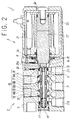
- the movable iron core 27 Upon supplying current to the coil 21, the movable iron core 27 is attracted toward the fixed iron core 26 and, as shown in Fig. 2, the position of the valve body 10 is switched in the rightward direction in the drawing under the influence of the biasing force of the valve spring 19.
- the communication between the inlet port P and the output port A is opened by the valve member 13a, while the communication between the inlet port P and the output port B is blocked by the valve member 13b.
- the communication between the output port A and the exhaust port EA is blocked by the valve member 14a, while the communication between the output port B and the exhaust port EB is opened by the valve member 14b.
- the valve can be put in the same position when the manual operating member 34 is pushed down as shown in the drawing without energizing the coil 21.
- first and second spring chambers 16 and 17 are communicated with each other by way of the axial through hole in the valve rod 11 of the valve body 10, which is provided with equalized pressure receiving areas at the opposite ends thereof, so that the pneumatic pressures acting on the opposite ends of the valve body 10 are constantly maintained in balanced state to ensure extremely smooth switching operations of the valve body.
- the valve body 10 can be put in smooth sliding movements under the guidance of the guide rings 15 free of inclinations or instable staggering motions.
- part of exhaust air to be discharged from the output port B to the exhaust port EB is allowed to flow into the second spring chamber 17 through the gap space 15a in the guide ring 15 and then into the first spring chamber 16 by way of the through hole 12 and the grooves 31 or notches 31a on the cushion member 30, and to leave through the exhaust port EA which is blocked against communication with the output port A. Therefore, by securing a suitable open area in the gap space 15a, it becomes possible to accelerate the exhaust air discharge speed with the effective use of the guide rings 15 which are primarily employed to ensure smooth movements of the valve rod 11 free of inclinations or other instable staggering motions.
- valve body 10 Upon cutting the current supply to the coil 21 or upon relieving the manual operating member 34 of the depressing force, the valve body 10 is returned to the initial position of Fig. 1 under the influence of the biasing force of the return spring 18.
- valve body 10 is moved in the same manner as described above, including the balanced actions on the valve body 10 by the pneumatic pressures prevailing in the first and second spring chambers 16 and 17 and the exhaust air discharging functions of the guide rings 15. Therefore, detailed descriptions in these respects are omitted to avoid unnecessary repetitions.
- a second embodiment of the balanced type direct-acting electromagnetic valve that is, a direct-acting electromagnetic valve 41 which differs from the foregoing first embodiment in that a main valve assembly 2 includes a base 43 serving as a manifold for connection of air pipes. More specifically, the electromagnetic valve 41 employs a valve casing 42 which has an inlet passage opening (p), output passage openings (a) and (b) and exhaust passage openings (ea) and (eb), which correspond to the inlet port P, output ports A and B and exhaust ports EA and EB of the first embodiment, all of the just-mentioned passages openings being opened on one side of the casing 42 to be joined with the base 43.
- an inlet passage opening 44 in communication with an inlet port (not shown), exhaust passages openings 45a and 45b respectively in communication with exhaust ports (not shown), and output passage openings 46a and 46b in communication with output ports 46A and 46B which are provided on the front side of the base 43.
- arrangements are made such that the respective passage openings on the part of the valve casing 42 are communicated with corresponding passage openings on the part of the base 43 upon mounting the valve casing 42 on the latter.
- the second embodiment is substantially same as the foregoing first embodiment in construction, so that common component parts are simply designated by common reference numerals without going into detailed description to avoid repetitions.
- the second embodiment functions substantially in the same manner as the first embodiment except that compressed air is fed to and discharged from the valve through the inlet passage 44 and exhaust passages 45 in the base 43 and output compressed air appears at either one of the output ports 46 on the front side of the base 43.
- the valve body which has been shown as having poppet type valve members in each one of the foregoing embodiments, may be replaced by a spool type valve body if desired.
- two exhaust ports which are provided separately in the above-described embodiments may be intercommunicated or merged into one and single exhaust port if desired.
- the balanced type direct-acting electromagnetic valve construction permits to switch the valve body quite easily and smoothly in a stabilized state, thanks to the application of balanced pneumatic pressures to the opposite ends of the valve body and under the guidance of the guide rings which are fitted on the opposite ends of the valve body.
- This valve construction suitably prevents scratchy contact between the valve body and the valve bore, which would shorten the service life of the electromagnetic valve itself as mentioned hereinbefore.
- the gap spaces which are provided in the guide rings permits to discharge the exhaust fluid simultaneously through the two exhaust ports, contributing to accelerate the fluid discharge speed.
Abstract
Description
- This invention relates to a direct-acting electromagnetic valve which is arranged to drive a valve body directly from an electromagnetic drive, and more particularly to a balanced type direct-acting electromagnetic valve in which fluid pressures are applied to the opposite ends of a valve body in a balanced state.
- In the direct-acting electromagnetic valves which are arranged to drive a valve body directly by means of an electromagnetic drive, it is desirable to balance the fluid pressures to be applied to the opposite ends of a valve body for the purpose of securing smooth movements of the valve body in operation.
- In this regard, Japanese Laid-Open Patent Application 61-096272 proposes a balanced type direct-acting electromagnetic valve, having chambers at the opposite ends of a valve body intercommunicated with each other by way of an axial hole formed internally of the valve body and having one of the chambers directly communicated with an exhaust port.
- According to the just-mentioned prior art electromagnetic valve, the fluid pressures prevailing in the chambers at the opposite ends of the valve body are balanced with each other through the intercommunicating axial through hole in the valve body, so that the position of the valve body can be switched relatively easily. In this case, however, the valve body is slidably supported in a valve bore only in part of its intermediate portion and disposed in a completely free state at its axially opposite end portions. This gives rise to problems such as inclinations or instable movements of the valve body which might take place while it is in movement for a switching operation. The inclinations of the valve body will result in scratchy contact of the valve body with the walls of the valve bore, causing malfunctioning in switching operations due to the instable staggering motions of the valve body or shortening the service life of the electromagnetic valve itself to a considerable degree.
- It is an object of the present invention to provide a balanced type direct-acting electromagnetic valve which is arranged to apply balanced fluid pressures to the opposite ends of a valve body, while ensuring stabilized smooth switching operations of the valve body free of inclinations or abrasive scratchy contact as mentioned above.
- In accordance with the present invention, the above-stated objective is achieved by the provision of a balanced type direct-acting electromagnetic valve including a main valve assembly incorporating a slidable valve body to switch the flow direction of a pressurized fluid and an electromagnetic drive having a movable iron core for directly driving the valve body, characterized in that: the main valve assembly comprises a casing internally defining a valve bore for receiving the valve body slidably therein, and having an inlet port opened into a center portion of the valve bore, a couple of output ports opened into the valve bore at positions axially on the opposite sides of the inlet port, a couple of exhaust ports opened into the valve bore at positions axially on the outer sides of the respective output ports, and a couple of chambers formed in association with the opposite ends of the valve bore; and the valve body comprises an axial through hole intercommunicating the two chambers, and a couple of guide rings fitted on circumferential surfaces of axially opposite end portions thereof and held in sliding contact win inner peripheral surfaces of the valve bore to guide movements of the valve body therealong, the guide rings being each formed with a gap space for communicating the two chambers with valve bore portions where the exhaust ports are opened, the valve body having equalized pressure receiving areas at the opposite ends thereof.
- In a more specific preferred form of the invention, the movable iron core of the electromagnetic drive is positioned in one of the chambers at the opposite ends of the valve bore along with a return spring member for biasing the movable iron core toward an initial or returned position, while a valve spring is provided in the other chamber for biasing the valve body toward the movable iron core.
- With the balanced type direct-acting electromagnetic valve of the above-described arrangements, the position of the valve body is switched upon energizing or de-energizing the electromagnetic drive. In this regard, since the chambers at the opposite ends of the valve bore are communicated with each other by way of the axial through hole in the valve body, the fluid pressures which act on the opposite ends of the valve body are constantly maintained in balanced state to facilitate the valve switching operations.
- Besides, the axially opposite end portions of the valve body are slidably supported by the guide rings which suitably prevent tilting motions of the valve body during the switching operations, permitting to switch the valve body in an extremely smooth and stabilized state free of scratchy contact which would lead to malfunctioning and shortened service life of the electromagnetic valve.
- Further, the fluid which flows from the inlet port to one exhaust port is allowed to flow into one of the chambers through the gap space in one guide ring and then into the other chamber through the axial through hole in the valve body. Simultaneously, the fluid is discharged through the other exhaust port via the gap space in the other guide ring, accelerating the fluid discharge speed.
- In the accompanying drawings:
- Fig. 1 is a longitudinally sectioned front view of a first embodiment of the balanced type direct-acting electromagnetic valve according to the invention, with its electromagnetic drive in de-energized state;
- Fig. 2 is a longitudinally sectioned front view of the electromagnetic valve of Fig. 1, with the electromagnetic drive in energized state;
- Fig. 3 is a left-hand side view of the electromagnetic valve of Fig. 1;
- Fig. 4 is an enlarged perspective view of a guide ring; and
- Fig. 5 is a longitudinally sectioned front view of a second embodiment of the balanced type direct-acting electromagnetic valve according to the invention, with the electromagnetic drive in energized state.
- Referring to Figs. 1 through 4, there is shown a first embodiment of the present invention, that is, a balanced type direct-acting
electromagnetic valve 1 which is largely constituted by amain valve assembly 2 and an electromagnetic drive orsolenoid assembly 3. - The
main valve assembly 2 includes: avalve casing 5 which is provided with avalve bore 6 for accommodating avalve body 10; a compressed air inlet port P which is opened substantially into a center portion of thevalve bore 6; a couple of output ports A and B which are opened into thevalve bore 6 at positions on the opposite sides of the inlet port P; and a couple of exhaust ports EA and EB which are opened into thevalve bore 6 at positions further on the outer sides of the output ports A and B. Aclosure member 8 is fixed in one end of thevalve bore 6 by means of astopper ring 7. Aseal member 8a is fitted around the outer periphery of theclosure member 8 to provide a hermetic seal therearound. The other end of thevalve bore 6 is hermetically closed with aseal member 9 which is held tight against theelectromagnetic drive assembly 3. - The
valve body 10 which is slidably received in thevalve bore 6 is provided with avalve rod 11, which is internally and centrally formed with an axial throughhole 12, poppettype valve members valve rod 11, andguide rings 15 fitted on axially opposite end portions of thevalve rod 11 for betterment of sliding characteristics of the valve body. When thevalve body 10 is moved in the leftward and rightward directions in the drawing, the communication of the output ports A and B with the inlet port P is either alternately closed and opened or alternately opened and closed by thevalve members valve members - The
valve body 10 is arranged to have equal pressure receiving areas at its axially opposite ends so that the forces of pneumatic pressures acting on its axially opposite ends are equalized with each other. - Further, a
first spring chamber 16 is defined between thevalve body 10 and theelectromagnetic drive assembly 3, while asecond spring chamber 17 is defined between thevalve body 10 and theclosure member 8. Areturn spring 18 is mounted in a charged state within thefirst spring chamber 16 to urge amovable iron core 27 in a returning direction, while avalve spring 19 with a smaller biasing force than thereturn spring 18 is mounted in a charged state within thesecond spring chamber 17 to urge thevalve body 10 toward themovable iron core 27. - The above-mentioned
valve members guide rings 15 are in the form of open rings of a polyamide or polyacetal resin or the like each with a gap space 15a as shown particularly in Fig. 4 to provide a flow passage thereacross. - Accordingly, the first and
second spring chambers hole 12 in thevalve rod 11, and at the same time communicated with the exhaust ports EA and EB through the gap spaces 15a in theguide rings 15, respectively. - The
electromagnetic drive 3 includes abobbin 22, asolenoid coil 21 wound on thebobbin 22, amagnetic frame 23 and amagnetic plate 24 enclosing thebobbin 22, a fixediron core 26 securely fixed in one end portion of a center hole of thebobbin 22 by means of abolt 25, and amovable iron core 27 slidably fitted in the center hole of thebobbin 22. The outer peripheral surfaces of themagnetic frame 23 is covered with amold 29 of a synthetic resin material. Themagnetic operating section 3 is hermetically attached to thevalve casing 5 on the side of thefirst spring chamber 17 by the use of bolts or other suitable means, in such a way that the afore-mentionedreturn spring 18 is interposed in a charged state between themagnetic plate 24 and themovable iron core 27.Seal rings 28 are fitted between thebobbin 22 and themagnetic plate 24 and between the center hole of thebobbin 22 and the fixediron core 26, respectively, to provide hermetic seals there. - A
cushion member 30 is fixedly attached to one end of thevalve rod 11 on the side of themovable iron core 27. More specifically, thiscushion member 30 is fixedly attached to thevalve rod 11 by way of a plural number of resiliently diverging spring strips 30a which are provided at its base portion and anchored in the throughhole 12 by press-fitting.Grooves 31 are cut into thecushion member 30 between the respective spring strips 30a thereby to communicate the axial throughhole 12 with thefirst spring chamber 16. - In order to communicate the axial through
hole 12 with thefirst spring chamber 16,notches 31a may be provided on the surface of thecushion member 30 which is abutted against thevalve rod 11, in place of or in addition to the above-describedgrooves 31. - Alternatively, if desired, there may be employed an arrangement of abutting the
movable iron core 27 andvalve rod 11 against each other directly without intervention of the above-describedcushion member 30. In such a case, needless to say, a suitable flow passage which corresponds to thegrooves 31 ornotches 31a needs to be formed between themovable iron core 27 andvalve rod 11. Besides, as a matter of course, even in a case where themovable iron core 27 is in a directly abutted position, there should be no change in the pressure receiving area on the abutting end face of thevalve rod 11. - Indicated at 34 in Fig. 1 is a manual operating member which can be manipulated for the purpose of moving the
movable iron core 27 by a manual operation, and at 37 is a printed wiring board which is mounted on theelectromagnetic drive assembly 3 for electrically connecting the coil terminals to an external power source. - Fig. 1 shows the valve in a de-energized state with no current supply to the
coil 21. In this state, thevalve body 10 occupies an initial or returned position under the influence of the biasing force of thereturn spring 18, where the communication between the inlet port P and the output port A is blocked by thevalve member 13a while the communication between the inlet port P and the output port B is opened by thevalve member 13b. Further, the communication between the output port A and the exhaust port EA is opened by thevalve member 14a while the communication between the output port B and the exhaust port EB is blocked by thevalve member 14b. - Upon supplying current to the
coil 21, themovable iron core 27 is attracted toward thefixed iron core 26 and, as shown in Fig. 2, the position of thevalve body 10 is switched in the rightward direction in the drawing under the influence of the biasing force of thevalve spring 19. In this position, the communication between the inlet port P and the output port A is opened by thevalve member 13a, while the communication between the inlet port P and the output port B is blocked by thevalve member 13b. At the same time, the communication between the output port A and the exhaust port EA is blocked by thevalve member 14a, while the communication between the output port B and the exhaust port EB is opened by thevalve member 14b. The valve can be put in the same position when themanual operating member 34 is pushed down as shown in the drawing without energizing thecoil 21. - In this instance, the first and
second spring chambers valve rod 11 of thevalve body 10, which is provided with equalized pressure receiving areas at the opposite ends thereof, so that the pneumatic pressures acting on the opposite ends of thevalve body 10 are constantly maintained in balanced state to ensure extremely smooth switching operations of the valve body. In addition, thevalve body 10 can be put in smooth sliding movements under the guidance of theguide rings 15 free of inclinations or instable staggering motions. - Further, part of exhaust air to be discharged from the output port B to the exhaust port EB is allowed to flow into the
second spring chamber 17 through the gap space 15a in theguide ring 15 and then into thefirst spring chamber 16 by way of the throughhole 12 and thegrooves 31 or notches 31a on thecushion member 30, and to leave through the exhaust port EA which is blocked against communication with the output port A. Therefore, by securing a suitable open area in the gap space 15a, it becomes possible to accelerate the exhaust air discharge speed with the effective use of theguide rings 15 which are primarily employed to ensure smooth movements of thevalve rod 11 free of inclinations or other instable staggering motions. - Upon cutting the current supply to the
coil 21 or upon relieving themanual operating member 34 of the depressing force, thevalve body 10 is returned to the initial position of Fig. 1 under the influence of the biasing force of thereturn spring 18. - At this time, the
valve body 10 is moved in the same manner as described above, including the balanced actions on thevalve body 10 by the pneumatic pressures prevailing in the first andsecond spring chambers guide rings 15. Therefore, detailed descriptions in these respects are omitted to avoid unnecessary repetitions. - Referring now to Fig. 5, there is shown a second embodiment of the balanced type direct-acting electromagnetic valve according to the present invention, that is, a direct-acting
electromagnetic valve 41 which differs from the foregoing first embodiment in that amain valve assembly 2 includes abase 43 serving as a manifold for connection of air pipes. More specifically, theelectromagnetic valve 41 employs avalve casing 42 which has an inlet passage opening (p), output passage openings (a) and (b) and exhaust passage openings (ea) and (eb), which correspond to the inlet port P, output ports A and B and exhaust ports EA and EB of the first embodiment, all of the just-mentioned passages openings being opened on one side of thecasing 42 to be joined with thebase 43. On the other hand, opened on one side of thebase 43, to be joined with thevalve casing 42, are an inlet passage opening 44 in communication with an inlet port (not shown),exhaust passages openings 45a and 45b respectively in communication with exhaust ports (not shown), and output passage openings 46a and 46b in communication withoutput ports base 43. In this case, arrangements are made such that the respective passage openings on the part of thevalve casing 42 are communicated with corresponding passage openings on the part of the base 43 upon mounting thevalve casing 42 on the latter. - In other respects, the second embodiment is substantially same as the foregoing first embodiment in construction, so that common component parts are simply designated by common reference numerals without going into detailed description to avoid repetitions.
- In operation, the second embodiment functions substantially in the same manner as the first embodiment except that compressed air is fed to and discharged from the valve through the inlet passage 44 and exhaust passages 45 in the
base 43 and output compressed air appears at either one of the output ports 46 on the front side of thebase 43. Needless to say, the valve body, which has been shown as having poppet type valve members in each one of the foregoing embodiments, may be replaced by a spool type valve body if desired. - Further, the two exhaust ports which are provided separately in the above-described embodiments may be intercommunicated or merged into one and single exhaust port if desired.
- As clear from the foregoing description, the balanced type direct-acting electromagnetic valve construction according to the present invention permits to switch the valve body quite easily and smoothly in a stabilized state, thanks to the application of balanced pneumatic pressures to the opposite ends of the valve body and under the guidance of the guide rings which are fitted on the opposite ends of the valve body. This valve construction suitably prevents scratchy contact between the valve body and the valve bore, which would shorten the service life of the electromagnetic valve itself as mentioned hereinbefore.
- In addition, the gap spaces which are provided in the guide rings permits to discharge the exhaust fluid simultaneously through the two exhaust ports, contributing to accelerate the fluid discharge speed.
Claims (2)
- A balanced type direct-acting electromagnetic valve including a main valve assembly incorporating a slidable valve body to switch the flow direction of a pressurized fluid and an electromagnetic drive having a movable iron core for directly driving said valve body, characterized in that:
said main valve assembly comprises a casing internally defining a valve bore for receiving said valve body slidably therein, and having an inlet port opened into a center portion of said valve bore, a couple of output ports opened into said valve bore at positions axially on the opposite sides of said inlet port, a couple of exhaust ports opened into said valve bore at positions axially on the outer sides of said respective output ports, and a couple of chambers formed in association with the opposite ends of said valve bore; and
said valve body comprises an axial through hole intercommunicating said two chambers, and a couple of guide rings fitted on circumferential surfaces of axially opposite end portions thereof and held in sliding contact with inner peripheral surfaces of said valve bore to guide movements of said valve body therealong, said guide rings being each formed with a gap space for communicating said two chambers with valve bore portions where said exhaust ports are opened, said valve body having equalized pressure receiving areas at the opposite ends thereof. - A balanced type direct-acting electromagnetic valve as defined in claim 1, wherein said movable iron core of said electromagnetic drive is positioned in one of said chambers at the opposite ends of said valve bore along with a return spring member for biasing said movable iron core toward an initial or returned position, and a valve spring is mounted in the other chamber for biasing said valve body toward said movable iron core.
Applications Claiming Priority (3)
| Application Number | Priority Date | Filing Date | Title |
|---|---|---|---|
| JP15925894A JP3451283B2 (en) | 1994-06-17 | 1994-06-17 | Balanced direct acting solenoid valve |
| JP15925894 | 1994-06-17 | ||
| JP159258/94 | 1994-06-17 |
Publications (2)
| Publication Number | Publication Date |
|---|---|
| EP0687843A1 true EP0687843A1 (en) | 1995-12-20 |
| EP0687843B1 EP0687843B1 (en) | 1999-06-16 |
Family
ID=15689835
Family Applications (1)
| Application Number | Title | Priority Date | Filing Date |
|---|---|---|---|
| EP19950302946 Expired - Lifetime EP0687843B1 (en) | 1994-06-17 | 1995-04-28 | Balanced type direct-acting electromagnetic valve |
Country Status (6)
| Country | Link |
|---|---|
| US (1) | US5535783A (en) |
| EP (1) | EP0687843B1 (en) |
| JP (1) | JP3451283B2 (en) |
| KR (1) | KR0182824B1 (en) |
| CN (1) | CN1043375C (en) |
| DE (1) | DE69510274T2 (en) |
Cited By (6)
| Publication number | Priority date | Publication date | Assignee | Title |
|---|---|---|---|---|
| FR2801416A1 (en) * | 1999-11-24 | 2001-05-25 | Parker Hannifin Rak Sa | MINIATURE SOLENOID VALVE, ASSEMBLY METHODS |
| WO2002018799A1 (en) * | 2000-08-31 | 2002-03-07 | Bosch Rexroth Ag | Unlockable non-return valve for very high system pressures |
| WO2002021032A1 (en) * | 2000-09-11 | 2002-03-14 | Bosch Rexroth Ag | Directional-control valve |
| EP2136117A3 (en) * | 2008-06-18 | 2013-04-24 | MAC Valves, Inc. | Balanced solenoid valve |
| CN103727266A (en) * | 2014-01-13 | 2014-04-16 | 宁夏丹辰科技有限公司 | Test solenoid valve |
| CN112405090A (en) * | 2020-11-20 | 2021-02-26 | 山东省机械设计研究院 | High-grade digit control machine tool main tapping electromagnetic suspension balanced system |
Families Citing this family (28)
| Publication number | Priority date | Publication date | Assignee | Title |
|---|---|---|---|---|
| US5927257A (en) * | 1997-09-19 | 1999-07-27 | Caterpillar Inc | Pressure compensating exhaust gas recirculation valve |
| US6220277B1 (en) * | 1997-10-07 | 2001-04-24 | Roy W. Blain | Flow metering solenoid valve |
| DE10106429A1 (en) * | 2001-02-16 | 2002-08-22 | Mannesmann Rexroth Ag | In particular, electromagnetically actuated directional seat valve in cartridge design |
| US20040171076A1 (en) * | 2001-12-20 | 2004-09-02 | Dejneka Matthew J. | Detectable micro to nano sized structures, methods of manufacture and use |
| US6640834B1 (en) * | 2002-08-06 | 2003-11-04 | Husco International, Inc. | Electrohydraulic valve for controlling a cam shaft phasing mechanism of an internal combustion engine |
| US20050145235A1 (en) * | 2003-02-11 | 2005-07-07 | Jong Paul G. | Trigger system for paintball marker |
| US6857423B2 (en) * | 2003-02-11 | 2005-02-22 | Paul Garfield Jong | Paintball marker and kit of parts therefor |
| JP4174670B2 (en) * | 2003-08-08 | 2008-11-05 | Smc株式会社 | Pilot operated solenoid valve |
| CA2459088C (en) * | 2004-02-27 | 2012-08-21 | Dana Canada Corporation | Leak-resistant solenoid valve |
| US20080099705A1 (en) * | 2006-10-25 | 2008-05-01 | Enfield Technologies, Llc | Retaining element for a mechanical component |
| US8151824B2 (en) * | 2007-04-05 | 2012-04-10 | Mac Valves, Inc. | Balanced solenoid valve |
| JP5560425B2 (en) | 2010-02-17 | 2014-07-30 | Smc株式会社 | Solenoid for solenoid valve |
| US8561644B2 (en) * | 2010-04-30 | 2013-10-22 | Technologies Holdings Corp. | Pulsator apparatus and method of operation |
| JP2012241740A (en) * | 2011-05-16 | 2012-12-10 | Denso Corp | Solenoid valve and hydraulic control device |
| DE102011055281B3 (en) * | 2011-11-11 | 2013-02-21 | Pierburg Gmbh | Valve device for a hydraulic circuit and oil pump control arrangement |
| US9103463B2 (en) * | 2012-02-14 | 2015-08-11 | Mac Valves, Inc. | Pressure balanced solenoid operated valve |
| KR101678426B1 (en) * | 2014-11-24 | 2016-11-22 | (주)패스텍 | Backflow preventing valve for cytology smear device |
| DE102016109865A1 (en) * | 2016-05-30 | 2017-11-30 | Eto Magnetic Gmbh | Electromagnetic valve device and system |
| CN106382384A (en) * | 2016-08-31 | 2017-02-08 | 宁波亚德客自动化工业有限公司 | Mechanical two-position five-way reversing valve |
| JP6533804B2 (en) * | 2017-03-27 | 2019-06-19 | Ckd株式会社 | solenoid valve |
| KR101999786B1 (en) | 2018-06-01 | 2019-07-12 | 신영제어기 주식회사 | Valve core and valve |
| DE102018208893A1 (en) * | 2018-06-06 | 2019-12-12 | Robert Bosch Gmbh | Direct controlled hydraulic directional valve |
| US11027909B2 (en) | 2018-08-15 | 2021-06-08 | Gpcp Ip Holdings Llc | Automated flowable material dispensers and related methods for dispensing flowable material |
| TWI684720B (en) * | 2018-12-12 | 2020-02-11 | 張睿彬 | Solenoid valve and manufacturing method for the same |
| DE102018132442B4 (en) * | 2018-12-17 | 2020-07-30 | Samson Aktiengesellschaft | Electropneumatic solenoid valve, field device with a solenoid valve and diagnostic procedure for an electro-pneumatic solenoid valve |
| EP3734126B1 (en) | 2019-05-03 | 2021-12-29 | Norgren AG | Directional control valve and a sealing arrangement therefor |
| CN113431946B (en) * | 2021-06-04 | 2022-06-14 | 杭州爱力智控技术有限公司 | Integrated pressure-adjustable electromagnetic directional valve |
| US20240093790A1 (en) * | 2022-09-16 | 2024-03-21 | Mac Valves, Inc. | Pilot valve having diaphragm |
Citations (2)
| Publication number | Priority date | Publication date | Assignee | Title |
|---|---|---|---|---|
| GB1202942A (en) * | 1966-11-05 | 1970-08-19 | Rexroth Gmbh G L | An improved longitudinal slide valve |
| EP0369090A1 (en) * | 1988-11-08 | 1990-05-23 | Refrigerating Machine Controls Ag (Rmc Ag) | Regulation valve with pressure compensation |
Family Cites Families (2)
| Publication number | Priority date | Publication date | Assignee | Title |
|---|---|---|---|---|
| US4574844A (en) * | 1984-11-13 | 1986-03-11 | Mac Valves, Inc. | Four-way poppet valve |
| US4611631A (en) * | 1985-01-24 | 1986-09-16 | Shoketsu Kinzoku Kogyo Kabushiki Kaisha | Solenoid operated poppet type change-over valve |
-
1994
- 1994-06-17 JP JP15925894A patent/JP3451283B2/en not_active Expired - Lifetime
-
1995
- 1995-04-26 US US08/427,850 patent/US5535783A/en not_active Expired - Lifetime
- 1995-04-28 EP EP19950302946 patent/EP0687843B1/en not_active Expired - Lifetime
- 1995-04-28 DE DE1995610274 patent/DE69510274T2/en not_active Expired - Lifetime
- 1995-05-26 KR KR1019950013416A patent/KR0182824B1/en not_active IP Right Cessation
- 1995-06-15 CN CN95106700A patent/CN1043375C/en not_active Expired - Lifetime
Patent Citations (2)
| Publication number | Priority date | Publication date | Assignee | Title |
|---|---|---|---|---|
| GB1202942A (en) * | 1966-11-05 | 1970-08-19 | Rexroth Gmbh G L | An improved longitudinal slide valve |
| EP0369090A1 (en) * | 1988-11-08 | 1990-05-23 | Refrigerating Machine Controls Ag (Rmc Ag) | Regulation valve with pressure compensation |
Cited By (10)
| Publication number | Priority date | Publication date | Assignee | Title |
|---|---|---|---|---|
| FR2801416A1 (en) * | 1999-11-24 | 2001-05-25 | Parker Hannifin Rak Sa | MINIATURE SOLENOID VALVE, ASSEMBLY METHODS |
| EP1103992A1 (en) * | 1999-11-24 | 2001-05-30 | Parker Hannifin Rak S.A. | Miniature electromagnetic valve and assembling procedure |
| WO2002018799A1 (en) * | 2000-08-31 | 2002-03-07 | Bosch Rexroth Ag | Unlockable non-return valve for very high system pressures |
| US6820645B2 (en) | 2000-08-31 | 2004-11-23 | Bosch Rexroth Ag | Unlockable non-return valve for very high system pressures |
| WO2002021032A1 (en) * | 2000-09-11 | 2002-03-14 | Bosch Rexroth Ag | Directional-control valve |
| US6916003B2 (en) | 2000-09-11 | 2005-07-12 | Bosch Rexroth Ag | Directional-control valve |
| EP2136117A3 (en) * | 2008-06-18 | 2013-04-24 | MAC Valves, Inc. | Balanced solenoid valve |
| CN103727266A (en) * | 2014-01-13 | 2014-04-16 | 宁夏丹辰科技有限公司 | Test solenoid valve |
| CN103727266B (en) * | 2014-01-13 | 2016-07-13 | 宁夏丹辰科技有限公司 | Test electromagnetic valve |
| CN112405090A (en) * | 2020-11-20 | 2021-02-26 | 山东省机械设计研究院 | High-grade digit control machine tool main tapping electromagnetic suspension balanced system |
Also Published As
| Publication number | Publication date |
|---|---|
| JPH084936A (en) | 1996-01-12 |
| CN1123893A (en) | 1996-06-05 |
| CN1043375C (en) | 1999-05-12 |
| DE69510274T2 (en) | 1999-10-14 |
| EP0687843B1 (en) | 1999-06-16 |
| JP3451283B2 (en) | 2003-09-29 |
| US5535783A (en) | 1996-07-16 |
| KR960001576A (en) | 1996-01-25 |
| KR0182824B1 (en) | 1999-04-15 |
| DE69510274D1 (en) | 1999-07-22 |
Similar Documents
| Publication | Publication Date | Title |
|---|---|---|
| US5535783A (en) | Balanced type direct-acting electromagnetic valve | |
| US7380571B2 (en) | Directional control valve | |
| US5558126A (en) | Double solenoid type electromagnetic valve | |
| US5615710A (en) | Pilot-type change-over valve | |
| EP1048854B1 (en) | Servo-driving pilot-type solenoid valve | |
| JPH07208625A (en) | Multiway valve | |
| EP0766030B1 (en) | Direct-coupled solenoid valve | |
| KR100476246B1 (en) | Proportional pressure control valve | |
| KR950000017B1 (en) | High speed solenoid valve device | |
| KR20030015139A (en) | Solenoid for electromagnetic valve | |
| JP3853700B2 (en) | solenoid valve | |
| JPH11218253A (en) | Proportional solenoid type direction throttle valve | |
| CN113048243A (en) | Valve body and step-by-step direct-acting electromagnetic valve | |
| JP3827833B2 (en) | solenoid valve | |
| JP2587536Y2 (en) | solenoid valve | |
| JP2001280519A (en) | Three-port solenoid valve | |
| JP2583766Y2 (en) | Pilot type solenoid valve | |
| JP2004011735A (en) | Solenoid valve | |
| CN108591542B (en) | Four-position double three-way electromagnetic valve | |
| JP4763500B2 (en) | Pilot type switching valve | |
| JP2719507B2 (en) | solenoid valve | |
| JPH017901Y2 (en) | ||
| JPH06700Y2 (en) | solenoid valve | |
| JP2587535Y2 (en) | solenoid valve | |
| JPS6217664Y2 (en) |
Legal Events
| Date | Code | Title | Description |
|---|---|---|---|
| PUAI | Public reference made under article 153(3) epc to a published international application that has entered the european phase |
Free format text: ORIGINAL CODE: 0009012 |
|
| 17P | Request for examination filed |
Effective date: 19950502 |
|
| AK | Designated contracting states |
Kind code of ref document: A1 Designated state(s): DE FR GB IT |
|
| 17Q | First examination report despatched |
Effective date: 19970725 |
|
| GRAG | Despatch of communication of intention to grant |
Free format text: ORIGINAL CODE: EPIDOS AGRA |
|
| GRAG | Despatch of communication of intention to grant |
Free format text: ORIGINAL CODE: EPIDOS AGRA |
|
| GRAH | Despatch of communication of intention to grant a patent |
Free format text: ORIGINAL CODE: EPIDOS IGRA |
|
| GRAH | Despatch of communication of intention to grant a patent |
Free format text: ORIGINAL CODE: EPIDOS IGRA |
|
| GRAA | (expected) grant |
Free format text: ORIGINAL CODE: 0009210 |
|
| AK | Designated contracting states |
Kind code of ref document: B1 Designated state(s): DE FR GB IT |
|
| REF | Corresponds to: |
Ref document number: 69510274 Country of ref document: DE Date of ref document: 19990722 |
|
| ET | Fr: translation filed | ||
| PLBE | No opposition filed within time limit |
Free format text: ORIGINAL CODE: 0009261 |
|
| STAA | Information on the status of an ep patent application or granted ep patent |
Free format text: STATUS: NO OPPOSITION FILED WITHIN TIME LIMIT |
|
| 26N | No opposition filed | ||
| PGFP | Annual fee paid to national office [announced via postgrant information from national office to epo] |
Ref country code: FR Payment date: 20010409 Year of fee payment: 7 |
|
| PGFP | Annual fee paid to national office [announced via postgrant information from national office to epo] |
Ref country code: GB Payment date: 20010425 Year of fee payment: 7 |
|
| REG | Reference to a national code |
Ref country code: GB Ref legal event code: IF02 |
|
| PG25 | Lapsed in a contracting state [announced via postgrant information from national office to epo] |
Ref country code: GB Free format text: LAPSE BECAUSE OF NON-PAYMENT OF DUE FEES Effective date: 20020428 |
|
| GBPC | Gb: european patent ceased through non-payment of renewal fee |
Effective date: 20020428 |
|
| PG25 | Lapsed in a contracting state [announced via postgrant information from national office to epo] |
Ref country code: FR Free format text: LAPSE BECAUSE OF NON-PAYMENT OF DUE FEES Effective date: 20021231 |
|
| REG | Reference to a national code |
Ref country code: FR Ref legal event code: ST |
|
| PG25 | Lapsed in a contracting state [announced via postgrant information from national office to epo] |
Ref country code: IT Free format text: LAPSE BECAUSE OF NON-PAYMENT OF DUE FEES;WARNING: LAPSES OF ITALIAN PATENTS WITH EFFECTIVE DATE BEFORE 2007 MAY HAVE OCCURRED AT ANY TIME BEFORE 2007. THE CORRECT EFFECTIVE DATE MAY BE DIFFERENT FROM THE ONE RECORDED. Effective date: 20050428 |
|
| PGFP | Annual fee paid to national office [announced via postgrant information from national office to epo] |
Ref country code: DE Payment date: 20140418 Year of fee payment: 20 |
|
| REG | Reference to a national code |
Ref country code: DE Ref legal event code: R071 Ref document number: 69510274 Country of ref document: DE |