EP0687834B1 - Dispositif de transmission comportant un tendeur piloté - Google Patents
Dispositif de transmission comportant un tendeur piloté Download PDFInfo
- Publication number
- EP0687834B1 EP0687834B1 EP95401373A EP95401373A EP0687834B1 EP 0687834 B1 EP0687834 B1 EP 0687834B1 EP 95401373 A EP95401373 A EP 95401373A EP 95401373 A EP95401373 A EP 95401373A EP 0687834 B1 EP0687834 B1 EP 0687834B1
- Authority
- EP
- European Patent Office
- Prior art keywords
- wheel
- rotation
- axis
- pinion
- tension
- Prior art date
- Legal status (The legal status is an assumption and is not a legal conclusion. Google has not performed a legal analysis and makes no representation as to the accuracy of the status listed.)
- Expired - Lifetime
Links
- 230000005540 biological transmission Effects 0.000 title claims description 11
- 238000006073 displacement reaction Methods 0.000 claims description 5
- 230000001360 synchronised effect Effects 0.000 claims 1
- 238000010276 construction Methods 0.000 description 3
- 238000010586 diagram Methods 0.000 description 3
- UXHQLGLGLZKHTC-CUNXSJBXSA-N 4-[(3s,3ar)-3-cyclopentyl-7-(4-hydroxypiperidine-1-carbonyl)-3,3a,4,5-tetrahydropyrazolo[3,4-f]quinolin-2-yl]-2-chlorobenzonitrile Chemical compound C1CC(O)CCN1C(=O)C1=CC=C(C=2[C@@H]([C@H](C3CCCC3)N(N=2)C=2C=C(Cl)C(C#N)=CC=2)CC2)C2=N1 UXHQLGLGLZKHTC-CUNXSJBXSA-N 0.000 description 1
- 230000003247 decreasing effect Effects 0.000 description 1
- 230000001939 inductive effect Effects 0.000 description 1
- 230000003071 parasitic effect Effects 0.000 description 1
Images

Classifications
-
- F—MECHANICAL ENGINEERING; LIGHTING; HEATING; WEAPONS; BLASTING
- F16—ENGINEERING ELEMENTS AND UNITS; GENERAL MEASURES FOR PRODUCING AND MAINTAINING EFFECTIVE FUNCTIONING OF MACHINES OR INSTALLATIONS; THERMAL INSULATION IN GENERAL
- F16H—GEARING
- F16H35/00—Gearings or mechanisms with other special functional features
- F16H35/08—Gearings or mechanisms with other special functional features for adjustment of members on moving parts from a stationary place
-
- F—MECHANICAL ENGINEERING; LIGHTING; HEATING; WEAPONS; BLASTING
- F16—ENGINEERING ELEMENTS AND UNITS; GENERAL MEASURES FOR PRODUCING AND MAINTAINING EFFECTIVE FUNCTIONING OF MACHINES OR INSTALLATIONS; THERMAL INSULATION IN GENERAL
- F16H—GEARING
- F16H7/00—Gearings for conveying rotary motion by endless flexible members
-
- F—MECHANICAL ENGINEERING; LIGHTING; HEATING; WEAPONS; BLASTING
- F41—WEAPONS
- F41A—FUNCTIONAL FEATURES OR DETAILS COMMON TO BOTH SMALLARMS AND ORDNANCE, e.g. CANNONS; MOUNTINGS FOR SMALLARMS OR ORDNANCE
- F41A9/00—Feeding or loading of ammunition; Magazines; Guiding means for the extracting of cartridges
- F41A9/50—External power or control systems
-
- Y—GENERAL TAGGING OF NEW TECHNOLOGICAL DEVELOPMENTS; GENERAL TAGGING OF CROSS-SECTIONAL TECHNOLOGIES SPANNING OVER SEVERAL SECTIONS OF THE IPC; TECHNICAL SUBJECTS COVERED BY FORMER USPC CROSS-REFERENCE ART COLLECTIONS [XRACs] AND DIGESTS
- Y10—TECHNICAL SUBJECTS COVERED BY FORMER USPC
- Y10T—TECHNICAL SUBJECTS COVERED BY FORMER US CLASSIFICATION
- Y10T74/00—Machine element or mechanism
- Y10T74/18—Mechanical movements
- Y10T74/18056—Rotary to or from reciprocating or oscillating
- Y10T74/18272—Planetary gearing and slide
Definitions
- the present invention relates to a transmission device comprising a central wheel movable in rotation about a first axis which is fixed and a satellite wheel movable in rotation around a second axis which is itself capable of moving according to a given trajectory with respect to the first axis without the satellite wheel rotating around the second axis, the central wheel and the satellite wheel being connected by a drive element forming a closed loop to drive the central wheel in mutual rotation and the satellite wheel.
- Such a transmission device can in particular be implemented in an ammunition conveyor in which the satellite wheel is a control pinion linked to the mask of the weapon and in which the central wheel is a pinion for controlling the movement of the ammunition in the conveyor, the central wheel and the satellite wheel being driven by a chain.
- the basic idea of the invention consists in at least partially compensating for this rotation induced by a counter-rotation obtained by varying the relative length of the arms of the drive element, for example a chain, between the central wheel and the satellite wheel.
- the transmission device is for this purpose characterized in that it comprises a controlled tensioner exerting a tension force on respectively a first and a second strand of the drive element which connects the central wheel and the satellite wheel and having a control means acting on the length of the first strand as a function of the displacement of the satellite wheel to at least partially compensate, by counter-rotation, for the rotation of the central wheel induced by said displacement of the satellite wheel.
- the control means advantageously comprises a connecting element having on the one hand a first articulation element allowing its rotation around a third axis which is fixed and which is parallel to the first axis, and on the other hand, a first arm connecting the first articulation element to the first tensioning wheel as well as a second arm connecting the first articulation element to a pin guided by a cam element having a profile allowing, by modifying the position of the first tensioning wheel, modify the length of the first strand.
- the drive element may be a chain or a toothed belt and the central wheel, the satellite wheel and the first and second tensioning wheels are then sprockets.
- first and second tensioning wheels are connected by a spring which tends to separate them from one another in order to tension both the first and the second strand.
- the device can then comprise a third arm having at a first end a second articulation element coaxial with the first articulation element to allow the third arm to rotate around the third axis, independently of the rotation of the connecting element, the second tension wheel being mounted at a second end of the third arm.
- the cam element is preferably a groove, the profile of which can be, at first approximation, an arc of a circle.
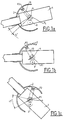
- a weapon 1 having a mask 2 can be pointed at different angles of elevation, for example -12 ° in Figure 1A, 0 ° in Figure 1B and + 45 ° in Figure 1C.
- the mask 2 has a pinion P2 called a satellite pinion whose function is to control an ammunition conveyor.
- the control pinion P2 drives the central pinion P1 whose axis is the axis of rotation in elevation of the weapon and the pinion P1 and the pinion P2 are connected by a closed chain 10.
- the rotation of the pinion P2 control causes that of the pinion P1 which, in turn, causes that of a mechanism 3 driving the ammunition conveyor.
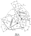
- FIGS 3a, 3b and 4 show a tensioner controlled according to the invention.
- the piloted tensioner comprises two tensioning pinions P3 and P4, the pinion P3 being intended to tension the strand 21 of the chain 20 between the pinions P1 and P2 and the pinion P4 being intended to tension the strand 22 between the pinions P1 and P2.
- the pinion P3 is movable in rotation around a point A, this rotation being controlled by a pin 50 guided by a cam 60.
- An arm 40 articulated at A on the fixing element which connects the pinion P3 and the pin 50, carries at one end the pinion P4.
- This articulated connection allows the pinion P4 to rotate around the articulation 33 and a spring 70 shown in FIG. 4 makes it possible to separate the pinions P3 and P4 from one another so as to obtain a substantially constant tension of the chain 20.
- the piloted tensioner comprising the connecting element 30, the arm 40 and the pinions P3 and P4, is fixed on a connecting element rigidly linking the pinions P1 and P2, this fixing allowing the free tensioning of the piloted tensioner around point A It will be noted that point A can be located outside the line connecting the axes of rotation of the pinions P1 and P2.
- the groove 60 acting as an interior and exterior cam in which the pin moves 50 is arranged on a fixed part 110 (see FIG. 7a) which does not rotate with the pinion P2.
- the position of the finger 50 defines the angle ⁇ (see fig. 4) existing between the tensioner and the axis connecting the pinions P1 and P2 and consequently the position of the pinion P3.
- the position of the sprocket P4 is a result of the position of the sprocket P3 and the total length of the chain.
- the position of the pinion P3 influences the length of the strand 21 connecting the pinions P1, P3, P2 between the points T1 and T2 defined in solid lines in FIG. 4 and correlatively on that of the strand 22 connecting the pinions P1, P4, P2.
- the pinion P2 not turning on itself, the variation in the length of the strand 21 connecting in this position the pinions P1, P3, P2 between the points T'1 and T2, results in a rotation of the pinion P1 on itself inducing a counter-rotation ⁇ ' 2 of the pinion P1 which makes it possible to cancel the rotation ⁇ 2 mentioned above.
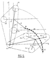
- FIG. 5 represents an example of construction of the profile of the cam 60. It is a question of determining a certain number of points for which the compensation is obtained.
- the profile of the cam 60 is very close to an arc of a circle, so that an approximate compensation can be obtained with a cam 70 forming an arc of a circle.
- Figures 4 and 5 show more precisely the kinematics of site placements.
- a rotation ⁇ 1 of the pinion P2 around P1 causes a first rotation ⁇ 2 of the pinion P1 on itself.
- the rotation ⁇ 1 of the pinion P2 around P1 also leads to a progression of the pin 50 in the groove 60 which controls the angle ⁇ (see FIG. 4) between the piloted tensioner and the axis connecting the axes of rotation of the pinions P1 and P2, hence the variation of the length of the strand 21 connecting the pinions P1, P3, P2 between the points T1 and T2.
- the profile of the cam 60 makes it possible, thanks to the pivoting ⁇ of the tensioner, to keep a constant length of chain 20 between the points T1 and T2 whatever the position of the pinion P2, the length of the strand 21 decreasing by the length of the arc of circle T1T'1 (figure 4). This corresponds to the reciprocal cancellation of the two rotations ⁇ 2 and ⁇ ' 2 , hence a resulting rotation of the pinion P1 on itself which is zero during a movement in elevation of the weapon 1.
- the piloted tensioner is mounted on a plate 100 carried by the mask 2, the mark 80 designating the input shaft controlling the rotation of the pinion P2, and the mark 90 representing the pivot axis of the pinion P1.
- the displacement of the pinion P4 can be obtained by guiding in translation, for example along the axis of the pinions P3 and P4 in place of the ball joint existing around A, a spring separating the pinions P3 therebetween and P4 and still making it possible to obtain a permanent tension of the chain 20.
- the movement of the pinion P2 is not necessarily a portion of a circle, it can also be a curve close to a portion of a circle or any other curve as far as it is always possible, by suitably choosing the profile of the cam 60 , to carry out at least partial compensation for the rotation of the pinion P1.
- condition of zero rotation of the pinion P1 can be replaced by another condition of imposed rotation which may or may not be linked to the other movements, this in order to obtain a particular function.
Landscapes
- Engineering & Computer Science (AREA)
- General Engineering & Computer Science (AREA)
- Mechanical Engineering (AREA)
- Devices For Conveying Motion By Means Of Endless Flexible Members (AREA)
- Transmission Devices (AREA)
Description
- La présente invention a pour objet un dispositif de transmission comprenant une roue centrale mobile en rotation autour d'un premier axe qui est fixe et une roue satellite mobile en rotation autour d'un deuxième axe qui est lui-même susceptible de se déplacer selon une trajectoire donnée par rapport au premier axe sans que la roue satellite n'effectue de rotation autour du deuxième axe, la roue centrale et la roue satellite étant reliées par un élément d'entraînement formant une boucle fermée pour entraîner en rotation mutuelle la roue centrale et la roue satellite.
- Un tel dispositif de transmission peut être en particulier mis en oeuvre dans un convoyeur à munitions dans lequel la roue satellite est un pignon de commande lié au masque de l'arme et dans lequel la roue centrale est un pignon de commande du mouvement des munitions dans le convoyeur, la roue centrale et la roue satellite étant entraînées par une chaîne.
- Une rotation θ1 de l'arme en site, et donc du pignon satellite lié au masque, entraîne une rotation θ2 similaire du pignon central qui commande le mouvement des munitions dans le convoyeur, en raison du fait que le pignon satellite n'effectue pas de rotation sur lui-même lors d'une rotation en site de l'arme.
- Cette rotation induite θ2 nuit au bon fonctionnement de l'arme et sa compensation au moins partielle ou son annulation constitue le problème à résoudre.
- L'idée de base de l'invention consiste à compenser au moins partiellement cette rotation induite par une contre-rotation obtenue en faisant varier la longueur relative des bras de l'élément d'entraînement, par exemple une chaîne, entre la roue centrale et la roue satellite.
- Le dispositif de transmission selon l'invention est dans ce but caractérisé en ce qu'il comporte un tendeur piloté exerçant une force de tension sur respectivement un premier et un deuxième brin de l'élément d'entraînement qui relie la roue centrale et la roue satellite et présentant un moyen de commande agissant sur la longueur du premier brin en fonction du déplacement de la roue satellite pour compenser au moins partiellement, par contre-rotation, la rotation de la roue centrale induite par ledit déplacement de la roue satellite.
- Le moyen de commande comporte avantageusement un élément de liaison présentant d'une part un premier élément d'articulation permettant sa rotation autour d'un troisième axe qui est fixe et qui est parallèle au premier axe, et d'autre part, un premier bras reliant le premier élément d'articulation à la première roue tendeuse ainsi qu'un deuxième bras reliant le premier élément d'articulation à un pion guidé par un élément de came ayant un profil permettant, en modifiant la position de la première roue tendeuse, de modifier la longueur du premier brin.
- L'élément d'entraînement peut être une chaîne ou une courroie crantée et la roue centrale, la roue satellite ainsi que la première et la deuxième roues tendeuses sont alors des pignons.
- Il est avantageux que la première et la deuxième roues tendeuses soient reliées par un ressort qui tend à les écarter l'une de l'autre pour tendre à la fois le premier et le deuxième brin.
- Le dispositif peut alors comporter un troisième bras présentant à une première extrémité un deuxième élément d'articulation coaxial au premier élément d'articulation pour permettre au troisième bras une rotation autour du troisième axe, indépendamment de la rotation de l'élément de liaison, la deuxième roue tendeuse étant montée à une deuxième extrémité du troisième bras.
- L'élément de came est de préférence une rainure dont le profil peut être en première approximation un arc de cercle.
- L'invention concerne également un système de pointage d'arme caractérisé en ce qu'il comporte un dispositif de transmission tel que défini ci-dessus et en ce que la roue centrale est une roue de commande du mouvement des munitions de l'arme et en ce que la roue satellite est une roue de commande liée au masque de pointage en site de l'arme, la trajectoire donnée correspondant aux pointages possibles de l'arme en site.
- L'invention sera mieux comprise à la lecture de la description qui va suivre, donnée à titre d'exemple non limitatif, en liaison avec les dessins dans lesquels :
- les figures 1a à 1c représentent un dispositif de pointage d'arme en site, selon différents angles de pointage en site ;
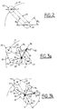
- la figure 2 est un schéma destiné à expliquer le problème posé dans le dispositif des figures 1A à 1C ;
- la figure 3a, 3b et 4 sont des schémas explicatifs du fonctionnement d'un dispositif selon un mode de réalisation préféré de l'invention ;
- la figure 5 est un schéma illustrant la construction géométrique du profil de l'élément de came ;
- la figure 6 représente un tendeur piloté selon l'invention ainsi que ses coupes partielles suivant A-A, B-B, D-D et C-C ;
- la figure 7a représente une coupe verticale du masque de pointage d'une arme avec enlèvement du tendeur piloté selon l'invention, et
- la figure 7b une vue de dessus du même masque sur lequel le tendeur piloté selon un mode de réalisation préféré de l'invention a été monté.
- Selon les figures 1a à 1c, une arme 1 présentant un masque 2 peut être pointée suivant différents angles de site, par exemple -12° à la figure 1A, 0° à la figure 1B et +45° à la figure 1C. Le masque 2 présente un pignon P2 dit pignon satellite dont la fonction est de commander un convoyeur de munitions. A cet effet, le pignon de commande P2 entraîne le pignon central P1 dont l'axe est l'axe de rotation en site de l'arme et le pignon P1 et le pignon P2 sont reliés par une chaîne fermée 10. La rotation du pignon de commande P2 entraîne celle du pignon P1 qui, à son tour, entraîne celle d'un mécanisme 3 entraînant le convoyeur de munitions.
- Une rotation θ1 de l'arme 1 en site, et donc du pignon de commande P2 lié au masque, entraîne une rotation θ2 similaire du pignon P1 de commande du mouvement des munitions dans le convoyeur car, lors d'une rotation en site de l'arme 1, le pignon P2 n'effectue pas de rotation sur lui-même. En effet, ce n'est que lors d'un tir, que le pignon P2 est entraîné en rotation et entraîne à son tour le convoyeur de munitions par l'intermédiaire du pignon P1 et du mécanisme 3.
- Cette rotation induite θ2 nuit au bon fonctionnement de l'arme 1 étant donné que la rotation en site de l'arme 1 entraîne un fonctionnement parasite non souhaité du convoyeur de munitions.
- Le problème peut s'expliciter de la manière suivante (voir la figure 2) :
- Soient deux pignons dentés P1 et P2 reliés par une chaîne 10, le pignon ayant une position fixe mais pouvant tourner sur lui-même, le pignon P2 tournant autour de P1 (θ) sans pouvoir tourner sur lui-même.
- Cette rotation θ1 entraîne une rotation θ2 du pignon sur lui-même avec θ1 = θ2 dans la configuration définie dans la figure 2.
- C'est donc cet angle θ2 qu'il convient de compenser au moins partiellement ou d'annuler.
- Les figures 3a, 3b et 4 représentent un tendeur piloté selon l'invention. Le tendeur piloté comporte deux pignons tendeurs P3 et P4, le pignon P3 étant destiné à tendre le brin 21 de la chaîne 20 entre les pignons P1 et P2 et le pignon P4 étant destiné à tendre le brin 22 entre les pignons P1 et P2. Le pignon P3 est mobile en rotation autour d'un point A, cette rotation étant commandée par un pion 50 guidé par une came 60.
- A cet effet, un élément de liaison 30 lie rigidement le pion 50 et le pignon P3 qui contient l'articulation 33 qui, en A, permet la fixation du tendeur piloté. L'élément de liaison 30 peut tourner librement autour de cette fixation. Un bras 31 de l'élément de liaison 30 relie l'articulation 33 et le pignon P3. Un bras 32 de l'élément de liaison 30 relie l'articulation 33 au pion 50.
- Un bras 40, articulé en A sur l'élément de fixation qui relie le pignon P3 et le pion 50, porte à une extrémité le pignon P4. Cette liaison articulée permet au pignon P4 de tourner autour de l'articulation 33 et un ressort 70 représenté à la figure 4 permet d'écarter l'un de l'autre les pignons P3 et P4 de manière à obtenir une tension sensiblement constante de la chaîne 20.
- Le tendeur piloté, comportant l'élément de liaison 30, le bras 40 et les pignons P3 et P4, est fixé sur un élément de liaison liant rigidement les pignons P1 et P2, cette fixation permettant la libre rotation du tendeur piloté autour du point A. On notera que le point A peut être situé en dehors de la ligne reliant les axes de rotation des pignons P1 et P2.
- La rainure 60 faisant office de came intérieure et extérieure dans laquelle se déplace le pion 50 est disposée sur une partie fixe 110 (voir figure 7a) ne tournant pas avec le pignon P2. La position du doigt 50 définit l'angle α (voir fig. 4) existant entre le tendeur et l'axe reliant les pignons P1 et P2 et par conséquent la position du pignon P3. La position du pignon P4 est une résultante de la position du pignon P3 et de la longueur totale de la chaîne.
- La position du pignon P3 influe sur la longueur du brin 21 reliant les pignons P1, P3, P2 entre les points T1 et T2 définis en traits pleins dans la figure 4 et corrélativement sur celle du brin 22 reliant les pignons P1, P4, P2. Pour une position en site donnée (en pointillés), le pignon P2 ne tournant pas sur lui-même, la variation de la longueur du brin 21 reliant dans cette position les pignons P1, P3, P2 entre les points T'1 et T2, se traduit par une rotation du pignon P1 sur lui-même induisant une contre-rotation θ'2 du pignon P1 qui permet d'annuler la rotation θ2 précitée.
- La figure 5 représente un exemple de construction du profil de la came 60. Il s'agit de déterminer un certain nombre de points pour lesquels la compensation est obtenue. Le profil de la came 60 est très voisin d'un arc de cercle, ce qui fait qu'une compensation approximative peut être obtenue avec une came 70 formant un arc de cercle.
- Le tendeur piloté selon l'invention présente ainsi deux fonctions :
- 1) pour une position en site donnée, il permet une transmission de puissance par le mouvement de la chaîne 20, c'est-à-dire qu'une rotation du pignon P2 sur lui-même entraîne une rotation sur lui-même du pignon P1, d'où l'entraînement du convoyeur à munitions ;
- 2) en l'absence de rotation du pignon P2 sur lui-même, c'est-à-dire sans transmission de puissance par la chaîne 20, il permet un mouvement en site de l'arme sans rotation θ2 du pignon P1 sur lui-même.
- Les figures 4 et 5 montrent plus précisément la cinématique des placements en site. Lorsque le pion 50 se déplace dans la rainure 60, une rotation θ1 du pignon P2 autour de P1 entraîne une première rotation θ2 du pignon P1 sur lui-même. Or, la rotation θ1 du pignon P2 autour de P1 entraîne aussi une progression du pion 50 dans la rainure 60 qui commande l'angle α (voir figure 4) entre le tendeur piloté et l'axe reliant les axes de rotation des pignons P1 et P2, d'où variation de la longueur du brin 21 reliant les pignons P1, P3, P2 entre les points T1 et T2. La variation induite de la longueur du brin 21 se traduit par une deuxième rotation θ'2 en sens inverse du pignon P1 sur lui-même d'où résulte une annulation de la rotation du pignon P1. Donc, la rotation θ1 en site entraîne une rotation α du tendeur piloté.
- Le profil de la came 60 permet grâce au pivotement α du tendeur de conserver une longueur de chaîne 20 constante entre les points T1 et T2 quelle que soit la position du pignon P2, la longueur du brin 21 diminuant de la longueur de l'arc de cercle T1T'1 (figure 4). Ceci correspond à l'annulation réciproque des deux rotations θ2 et θ'2, d'où une rotation résultante du pignon P1 sur lui-même qui est nulle lors d'un mouvement en site de l'arme 1.
- Ce dispositif qui fonctionne de manière totalement mécanique et automatique, simplement par la mise en oeuvre du tendeur piloté décrit ci-dessus se prête à une réalisation simple et fiable.
- En se reportant maintenant aux figures 6, 7a et 7b, on voit que le tendeur piloté est monté sur une platine 100 portée par le masque 2, le repère 80 désignant l'arbre d'entrée commandant la rotation du pignon P2, et le repère 90 représentant l'axe de pivotement du pignon P1.
- Le ressort 70 est monté entre deux points d'accrochage 71 et 72 situés approximativement à mi-longueur des bras 31 et 40. La coupe A-A de la figure 6 montre également que le bras 40 qui porte le pignon P4 est articulé en 41 à l'intérieur de l'articulation 33 de l'élément de liaison 30.
- L'invention ne se limite pas aux modes de réalisations décrits et représentés.
- En particulier, le déplacement du pignon P4 peut être obtenu par un guidage en translation, par exemple selon l'axe des pignons P3 et P4 à la place de la liaison par rotule existant autour de A, un ressort écartant entre eux les pignons P3 et P4 et permettant toujours d'obtenir une tension permanente de la chaîne 20.
- Le mouvement du pignon P2 n'est pas nécessairement une portion de cercle, il peut être également une courbe proche d'une portion de cercle ou tout autre courbe dans la mesure où il est toujours possible, en choisissant convenablement le profil de la came 60, de réaliser une compensation au moins partielle de la rotation du pignon P1.
- Il va de soi en particulier en condition de rotation nulle du pignon P1 peut être remplacée par une autre condition de rotation imposée qui peut être liée ou non aux autres mouvements, ceci afin d'obtenir une fonction particulière.
- Il est possible en pratique de déterminer par le calcul le profil de la came 60, ou bien, empiriquement, en pointant un certain nombre de positions caractéristiques du pion 50 obtenues en positionnant manuellement le tendeur piloté dans des positions correspondant à l'obtention de la compensation angulaire recherchée.
Claims (10)
- Dispositif de transmission comprenant une roue centrale mobile en rotation autour d'un premier axe qui est fixe et une roue satellite mobile en rotation autour d'un deuxième axe qui est lui-même susceptible de se déplacer selon une trajectoire donnée par rapport au premier axe sans que la roue satellite n'effectue de rotation autour du deuxième axe, la roue centrale et la roue satellite étant reliées par un élément d'entraînement formant une boucle fermée pour entraîner en rotation mutuelle la roue centrale et la roue satellite, caractérisé en ce qu'il comporte un tendeur piloté exerçant une force de tension sur respectivement un premier (21) et un deuxième (22) brin de l'élément d'entraînement (20) qui relient la roue centrale (P1) et la roue satellite (P2) et présentant un moyen de commande agissant sur la longueur du premier (21) brin en fonction du déplacement (θ1) de la roue satellite (P2) pour compenser au moins partiellement par contre-rotation la rotation (θ2) de la roue centrale (P1) induite par ledit déplacement (θ1) de la roue satellite (P2).
- Dispositif selon la revendication 1 caractérisé en ce que le tendeur piloté comporte une première (T3) et une deuxième (T4) roues tendeuses rappelées par ressort ainsi qu'un élément de liaison (30) présentant d'une part un premier élément d'articulation (33) permettant sa rotation autour d'un troisième axe qui est fixe et qui est parallèle au premier axe, et d'autre part un premier bras (31) reliant le premier élément d'articulation (33) à la première roue tendeuse (P3) ainsi qu'un deuxième bras (32) reliant le premier élément d'articulation (33) à un pion (50) guidé par un élément de came (60) ayant un profil permettant, en modifiant la position de la première roue tendeuse (T3), de modifier la longueur du premier brin (21).
- Dispositif selon la revendication 2 caractérisé en ce que l'élément d'entraînement (20) est une chaîne ou une courroie crantée et en ce que la roue centrale (P1), la roue satellite (P2), ainsi que la première (P3) et la deuxième (P4) roues tendeuses sont des pignons.
- Dispositif selon l'une des revendications 2 ou 3 caractérisé en ce que la première (P3) et la deuxième (P4) roues tendeuses sont reliées par un ressort (70) qui tend à les écarter l'une de l'autre pour tendre à la fois le premier (21) et le deuxième brin (22).
- Dispositif selon la revendication 4 caractérisé en ce qu'il comporte un troisième bras (40) présentant à une première extrémité un deuxième élément d'articulation (41) coaxial au premier élément d'articulation (33) pour permettre au troisième bras (40) une rotation autour d'un troisième axe, indépendamment de la rotation de l'élément de liaison (30), la deuxième roue tendeuse (P4) étant montée à une deuxième extrémité du troisième bras (40).
- Dispositif selon l'une des revendications 2 à 5 caractérisé en ce que l'élément de came est une rainure (60).
- Dispositif selon l'une des revendications 2 à 6 caractérisé en ce que le profil de l'élément de came (60) est un arc de cercle.
- Dispositif selon l'une des revendications 2 à 7 caractérisé en ce que la trajectoire donnée du deuxième axe est un arc de cercle ou un cercle.
- Dispositif selon l'une des revendications précédentes caractérisé en ce que le premier, le deuxième et le troisième axes sont parallèles et coplanaires.
- Système de pointage d'arme caractérisé en ce qu'il comporte un dispositif de transmission selon l'une des revendications précédentes et en ce que la roue centrale (P1) est une roue de commande du mouvement des munitions de l'arme et en ce que la roue satellite (P2) est une roue de commande liée au masque (2) de pointage en site de l'arme, la trajectoire donnée correspondant aux pointages possibles de l'arme en site.
Applications Claiming Priority (2)
| Application Number | Priority Date | Filing Date | Title |
|---|---|---|---|
| FR9407354 | 1994-06-16 | ||
| FR9407354A FR2721366B1 (fr) | 1994-06-16 | 1994-06-16 | Dispositif de transmission comportant un tendeur piloté. |
Publications (2)
| Publication Number | Publication Date |
|---|---|
| EP0687834A1 EP0687834A1 (fr) | 1995-12-20 |
| EP0687834B1 true EP0687834B1 (fr) | 1997-07-16 |
Family
ID=9464271
Family Applications (1)
| Application Number | Title | Priority Date | Filing Date |
|---|---|---|---|
| EP95401373A Expired - Lifetime EP0687834B1 (fr) | 1994-06-16 | 1995-06-13 | Dispositif de transmission comportant un tendeur piloté |
Country Status (4)
| Country | Link |
|---|---|
| US (1) | US5750916A (fr) |
| EP (1) | EP0687834B1 (fr) |
| DE (1) | DE69500437T2 (fr) |
| FR (1) | FR2721366B1 (fr) |
Family Cites Families (5)
| Publication number | Priority date | Publication date | Assignee | Title |
|---|---|---|---|---|
| US3750972A (en) * | 1971-02-23 | 1973-08-07 | J Bonnabaud | Automatic tension regulation of yarn and wire winding devices |
| CH601697A5 (en) * | 1977-02-14 | 1978-07-14 | Wilhelm Ruetschi | converter for continuous wheel rotation into periodic rotation |
| GB8712945D0 (en) * | 1987-06-25 | 1987-07-08 | Stidworthy F M | Variable valves |
| US5212338A (en) * | 1991-07-05 | 1993-05-18 | General Electric Co. | Ammunition transfer apparatus for uploading and downloading a magazine |
| FR2691529B1 (fr) * | 1992-05-21 | 1994-08-19 | Giat Ind Sa | Système de chargement d'une munition, telle qu'une munition télescopée dans une chambre pivotante d'une arme. |
-
1994
- 1994-06-16 FR FR9407354A patent/FR2721366B1/fr not_active Expired - Fee Related
-
1995
- 1995-06-13 EP EP95401373A patent/EP0687834B1/fr not_active Expired - Lifetime
- 1995-06-13 DE DE69500437T patent/DE69500437T2/de not_active Expired - Fee Related
- 1995-06-15 US US08/490,719 patent/US5750916A/en not_active Expired - Fee Related
Also Published As
| Publication number | Publication date |
|---|---|
| FR2721366B1 (fr) | 1996-08-14 |
| DE69500437T2 (de) | 1998-02-05 |
| DE69500437D1 (de) | 1997-08-21 |
| US5750916A (en) | 1998-05-12 |
| EP0687834A1 (fr) | 1995-12-20 |
| FR2721366A1 (fr) | 1995-12-22 |
Similar Documents
| Publication | Publication Date | Title |
|---|---|---|
| EP2981739A1 (fr) | Verin a cable permettant un debattement articulaire augmente | |
| EP0171318B1 (fr) | Dispositif de réglage de la position de projecteurs de véhicules | |
| FR2460762A1 (fr) | Dispositif pour la commande de l'orientation d'un outil ou d'un element analogue par rapport a une piece | |
| FR2539346A1 (fr) | Dispositif manipulateur automatique articule notamment pour le soudage a l'arc | |
| EP1538067B1 (fr) | Essieu pour véhicule automobile et actionneur d'un tel essieu | |
| US4824420A (en) | Rear derailer for bicycle gears | |
| FR2539664A1 (fr) | Mecanisme d'articulation pour dispositif manipulateur automatique de soudage a l'arc | |
| EP0687834A1 (fr) | Dispositif de transmission comportant un tendeur piloté | |
| EP0115224B1 (fr) | Dispositif de commande de boîte de vitesses avec tige sur rotule coulissante | |
| EP0056550A2 (fr) | Dispositif d'orientation selon deux axes orthogonaux, en particulier pour une antenne hyperfréquence | |
| FR2596345A1 (fr) | Dispositif pour essuyer les glaces de vehicules automobiles pour agrandir l'amplitude du mouvement de translation de la bielle et la zone de balayage | |
| EP0010476B1 (fr) | Mécanisme pour l'obtention d'une trajectoire fermée de forme désirée | |
| WO2019145611A1 (fr) | Machine tronçonneuse de rails d'une voie de chemin de fer | |
| WO2004089578A2 (fr) | Dispositif d'actionnement, notamment pour un bras articule | |
| EP0007861B1 (fr) | Dispositif de réglage d'un rétroviseur notamment pour véhicule | |
| EP3381759A1 (fr) | Liaison mecanique a double liaison pivot, et vehicule ferroviaire comportant une telle liaison mecanique | |
| FR2672859A1 (fr) | Installation d'essuie-glace pour vehicule automobile. | |
| EP0406096B1 (fr) | Dispositif d'essuie-glace à balayage non circulaire, notamment pour véhicule automobile | |
| EP0084472A1 (fr) | Dispositif de commande de boîte de vitesses | |
| FR2476862A1 (fr) | Systeme de transport de film | |
| EP0061155B1 (fr) | Dispositif d'orientation d'un outil | |
| FR2610859A1 (fr) | Robot a plusieurs bras, equipes de mecanismes de coordination des mouvements de ces bras | |
| EP0433173A1 (fr) | Mécanisme de commande motorisée d'une porte à déplacement latéral munie d'un portillon | |
| FR2863534A1 (fr) | Articulation de bras mecanique et bras pourvu de cette articulation | |
| FR3135796A3 (fr) | Aiguille d’affichage flexible et mécanisme d’actionnement d’une telle aiguille d’affichage |
Legal Events
| Date | Code | Title | Description |
|---|---|---|---|
| PUAI | Public reference made under article 153(3) epc to a published international application that has entered the european phase |
Free format text: ORIGINAL CODE: 0009012 |
|
| AK | Designated contracting states |
Kind code of ref document: A1 Designated state(s): CH DE GB LI SE |
|
| 17P | Request for examination filed |
Effective date: 19960201 |
|
| GRAG | Despatch of communication of intention to grant |
Free format text: ORIGINAL CODE: EPIDOS AGRA |
|
| GRAH | Despatch of communication of intention to grant a patent |
Free format text: ORIGINAL CODE: EPIDOS IGRA |
|
| 17Q | First examination report despatched |
Effective date: 19961210 |
|
| GRAH | Despatch of communication of intention to grant a patent |
Free format text: ORIGINAL CODE: EPIDOS IGRA |
|
| GRAA | (expected) grant |
Free format text: ORIGINAL CODE: 0009210 |
|
| AK | Designated contracting states |
Kind code of ref document: B1 Designated state(s): CH DE GB LI SE |
|
| REG | Reference to a national code |
Ref country code: CH Ref legal event code: EP |
|
| REF | Corresponds to: |
Ref document number: 69500437 Country of ref document: DE Date of ref document: 19970821 |
|
| PG25 | Lapsed in a contracting state [announced via postgrant information from national office to epo] |
Ref country code: SE Effective date: 19971016 |
|
| GBT | Gb: translation of ep patent filed (gb section 77(6)(a)/1977) |
Effective date: 19970929 |
|
| PLBE | No opposition filed within time limit |
Free format text: ORIGINAL CODE: 0009261 |
|
| STAA | Information on the status of an ep patent application or granted ep patent |
Free format text: STATUS: NO OPPOSITION FILED WITHIN TIME LIMIT |
|
| 26N | No opposition filed | ||
| PG25 | Lapsed in a contracting state [announced via postgrant information from national office to epo] |
Ref country code: LI Free format text: LAPSE BECAUSE OF NON-PAYMENT OF DUE FEES Effective date: 19990630 Ref country code: CH Free format text: LAPSE BECAUSE OF NON-PAYMENT OF DUE FEES Effective date: 19990630 |
|
| REG | Reference to a national code |
Ref country code: CH Ref legal event code: PL |
|
| REG | Reference to a national code |
Ref country code: GB Ref legal event code: IF02 |
|
| PGFP | Annual fee paid to national office [announced via postgrant information from national office to epo] |
Ref country code: GB Payment date: 20050527 Year of fee payment: 11 Ref country code: DE Payment date: 20050527 Year of fee payment: 11 |
|
| PG25 | Lapsed in a contracting state [announced via postgrant information from national office to epo] |
Ref country code: GB Free format text: LAPSE BECAUSE OF NON-PAYMENT OF DUE FEES Effective date: 20060613 |
|
| PG25 | Lapsed in a contracting state [announced via postgrant information from national office to epo] |
Ref country code: DE Free format text: LAPSE BECAUSE OF NON-PAYMENT OF DUE FEES Effective date: 20070103 |
|
| GBPC | Gb: european patent ceased through non-payment of renewal fee |
Effective date: 20060613 |