EP0687621A2 - Brake system for motorcycles - Google Patents
Brake system for motorcycles Download PDFInfo
- Publication number
- EP0687621A2 EP0687621A2 EP95109047A EP95109047A EP0687621A2 EP 0687621 A2 EP0687621 A2 EP 0687621A2 EP 95109047 A EP95109047 A EP 95109047A EP 95109047 A EP95109047 A EP 95109047A EP 0687621 A2 EP0687621 A2 EP 0687621A2
- Authority
- EP
- European Patent Office
- Prior art keywords
- liquid pressure
- front wheel
- master cylinder
- brake
- piston
- Prior art date
- Legal status (The legal status is an assumption and is not a legal conclusion. Google has not performed a legal analysis and makes no representation as to the accuracy of the status listed.)
- Granted
Links
Images


Classifications
-
- B—PERFORMING OPERATIONS; TRANSPORTING
- B60—VEHICLES IN GENERAL
- B60T—VEHICLE BRAKE CONTROL SYSTEMS OR PARTS THEREOF; BRAKE CONTROL SYSTEMS OR PARTS THEREOF, IN GENERAL; ARRANGEMENT OF BRAKING ELEMENTS ON VEHICLES IN GENERAL; PORTABLE DEVICES FOR PREVENTING UNWANTED MOVEMENT OF VEHICLES; VEHICLE MODIFICATIONS TO FACILITATE COOLING OF BRAKES
- B60T8/00—Arrangements for adjusting wheel-braking force to meet varying vehicular or ground-surface conditions, e.g. limiting or varying distribution of braking force
- B60T8/26—Arrangements for adjusting wheel-braking force to meet varying vehicular or ground-surface conditions, e.g. limiting or varying distribution of braking force characterised by producing differential braking between front and rear wheels
- B60T8/261—Arrangements for adjusting wheel-braking force to meet varying vehicular or ground-surface conditions, e.g. limiting or varying distribution of braking force characterised by producing differential braking between front and rear wheels specially adapted for use in motorcycles
-
- B—PERFORMING OPERATIONS; TRANSPORTING
- B62—LAND VEHICLES FOR TRAVELLING OTHERWISE THAN ON RAILS
- B62L—BRAKES SPECIALLY ADAPTED FOR CYCLES
- B62L3/00—Brake-actuating mechanisms; Arrangements thereof
- B62L3/08—Mechanisms specially adapted for braking more than one wheel
Definitions
- the present invention relates to a brake system for a motorcycle, in which a common master cylinder is connected with a front wheel brake to be mounted on a front wheel and a rear wheel brake to be mounted on a rear wheel.
- the master cylinder for generating a liquid pressure by depressing a brake pedal is connected with the front wheel brake and the rear wheel brake, and the output liquid pressure of the master cylinder acts directly upon the front wheel brake.
- the front wheel is excessively braked to raise the motorcycle body even if the brake pedal is depressed relatively weakly for adjusting the running speed while the motorcycle is turning, so that the braking force to be distributed to the front wheel cannot be increased.
- the present invention has been conceived in view of such background and has for its object to provide a brake system for a motorcycle, which is enabled to change the distribution of the braking force at the front wheel side between two states in which the output liquid pressure of the master cylinder is relatively low and high.
- a brake system for a motorcycle in which a common master cylinder is connected with front wheel brakes to be mounted on a front wheel and with a rear wheel brake to be mounted on a rear wheel, characterized in that there is mounted on the front wheel a plurality of front wheel brakes of which the front wheel brake is connected directly with the master cylinder and the other front wheel brake is connected with the master cylinder through pressure control means for changing the liquid pressure transmission ratio in accordance with the output liquid pressure of the master cylinder.
- the pressure control means can be switched between a state, in which it intercepts the liquid pressure transmission when the output liquid pressure of the master cylinder is lower than a predetermined level, and a state in which it transmits the liquid pressure when the output liquid pressure of the master cylinder is equal to or higher than the predetermined level.
- one of the front wheel brake is equipped with a secondary master cylinder for establishing a liquid pressure by a brake reaction to be established in response to the action of the front wheel brake, and the secondary master cylinder is connected with the rear wheel brake.
- Figs. 1 to 6 show one embodiment of the present invention wherein Fig. 1 is a top plan view of a motorcycle equipped with a brake system according to the present invention
- Fig. 2 is a diagram of the entire construction of the brake system
- Fig. 3 is a longitudinal section of a secondary master cylinder
- Fig. 4 is a longitudinal section of a pressure-reducing device
- Fig. 5 is a diagram of the pressure-reducing characteristics of the pressure-reducing device
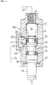
- Fig. 6 is a longitudinal section of pressure control means.
- a first front wheel brake B F1 and a second front wheel brake B F2 are respectively mounted on the righthand and lefthand sides of a front wheel W F in a motorcycle V, and a rear wheel brake B R is mounted On the righthand side of a rear wheel W R .
- a primary master cylinder M L for outputting a liquid pressure according to the actuation of a brake lever 2.
- a second master cylinder M P for outputting a liquid pressure according to the depression of a brake pedal 4.
- the brake lever 2 when the brake lever 2 is solely actuated while the brake pedal 4 is left unactuated, the first and second front wheel brakes B F1 and B F2 and the rear wheel brake B R are operated by the liquid pressure outputted from the primary master cylinder M L .
- the brake pedal 4 is solely actuated while the brake lever 2 is left unactuated, the first front wheel brake B F1 and the rear wheel brake B R are operated, but the second front wheel brake B F2 is not operated when the actuating force of the brake pedal 4 is relatively low but is operated when the actuating force of the brake pedal 4 is relatively high.
- the first front wheel brake B F1 is a disc brake which is slidably fitted in a caliper 6 with the rear piston P A , a central piston P B and a rear piston P C in a caliper 61 while having surfaces of its central piston P B and rear piston P C confronting liquid pressure chambers 5 A , 5 B and 5 C , respectively.
- the second front wheel brake B F2 is a disc brake which is slidably fitted in a caliper 62 with the rear surfaces of its front piston P D , central piston P E and rear piston P F confronting liquid pressure chambers 5 C , 5 E and 5 F , respectively.
- the rear wheel brake B R is a disc brake which is slidably fitted in a caliper 63 with its front piston P G , central piston P H and rear piston P1 confronting liquid pressure chambers 5 G , 5 H and 5 I , respectively.
- the primary master cylinder M L is connected directly with the liquid pressure chambers 5 A and 5 B of the first front wheel brake B F1 and directly to the liquid pressure chambers 5 D and 5 F of the second front wheel brake B F2 .
- the first front wheel brake B F1 is equipped with a secondary master cylinder M S for generating a liquid pressure by the brake reaction which is generated according to the action of the first front wheel brake B F1 .
- This secondary master cylinder M S is connected through a pressure-reducing device 7 to the liquid pressure chambers 5 G and 5 I of the rear wheel brake B R .
- the second master cylinder M P is connected directly with the liquid pressure chamber 5 H of the rear wheel brake B R and the liquid pressure chamber 5 B of the first front wheel brake B F1 and through pressure control means 8 with the liquid pressure chamber 5 E of the second front wheel brake B F2 .
- the secondary master cylinder M S has its cylinder body 9 formed into such a bottomed cylindrical shape having an output port 10 in its one closed end.
- a piston 12 In this cylinder body 9, there is slidably fitted a piston 12 to define an output liquid pressure chamber 11 leading to the output port 10 between the closed end portion of the cylinder body 9 and one end of the piston 12.
- a return spring 13 In the output liquid pressure chamber 11 between one end of the cylinder body 9 and the piston 12, there is compressed a return spring 13 for urging the piston 12 in the direction to increase the volume of the output liquid pressure chamber 11.
- the piston 12 has its intermediate portion radially reduced at its outer circumference to form an annular chamber 14 between itself and the inner circumference of the cylinder body 9.
- first and second cup seals 15 and 16 which define the annular chamber 14 therebetween.
- the first cup seal 15, as located between the annular chamber 14 and the output liquid pressure chamber 11, is in sliding contact with the inner circumference of the cylinder body 9 to permit communication of the working liquid from the annular chamber 14 to the output liquid pressure chamber 11 but obstruct the communication of the working liquid from the output liquid pressure chamber 11 to the annular chamber 14 when the pressure in the output liquid pressure chamber 11 is lower than that in the annular chamber 14.
- the second seal 16 is in sliding contact with the inner circumference of the cylinder body 9 to obstruct the communication of the working liquid with the side opposite to the output liquid pressure chamber 11.
- a stop ring 17 By which is slidably fitted a disc-shaped push plate 18 in the cylinder body 9 while being obstructed from coming out.
- the push plate 18 is in coaxial contact with the other end of the piston 12. From the push plate 18, moreover, there is coaxially and integrally extended a rod 9 which extends away from the piston 12.
- a cover 21 for forming a reserving chamber 20 between itself and the outer circumference of the cylinder body 9.
- This cylinder body 9 is formed in its side wall with a primary port 22 for opening the output liquid pressure chamber 11 into the reserving chamber 20 when the piston 12 is in the position to maximize the volume of the output liquid pressure chamber 11, as shown in Fig. 3 and a secondary port 23 for communicating the annular chamber 14 with the reserving chamber 20 at all times.
- the caliper 61 of the first front wheel brake B F1 is equipped, as shown in Fig. 2, with a connection arm 24 which is associated and connected to the rod 19.
- the connection arm 24 acts to push the rod 19 upward so that the piston 12 acts in the direction to reduce the volume of the output liquid pressure chamber 11.
- the piston 12 reduces the volume of the output liquid pressure chamber 11, even after the first cup seal 15 passes the primary port 22 to intercept the communication between the reserving chamber 20 and the output liquid pressure chamber 11, so that the liquid pressure is outputted from the output liquid pressure chamber 11, i.e., the output port 10.
- This output port 10 is connected through a conduit 24 with the pressure-reducing device 7, and a conduit 25 connected with the reserving chamber 20 is connected with the liquid pressure chamber 5 H of the rear wheel brake B R and the second master cylinder M P .
- the pressure-reducing device 7 is equipped with a proportional pressure-reducing valve 27 and pressure-reducing means 28.
- the proportional pressure-reducing valve 27 has its housing 29 formed with a first spring housing hole 30 having its one end opened a first sliding hole 31 radially reduced from the first spring housing hole 30 and having its one end coaxially leading to the other end of the first spring housing hole 30 a second sliding hole 32 radially enlarged from the first sliding hole 31 and having its one end coaxially leading to the other end of the first sliding hole 31 and a second spring housing hole 33 radially enlarged from the second sliding hole 32 and having its one end coaxially leading to the other end of the second sliding hole 32 and its other end opened.
- a regulation piston 36 which is formed at its intermediate portion with such a flanged portion 36a as can abut against a stepped portion 34 between the first spring housing hole 30 and the first sliding hole 31.
- a regulation spring 39 is compressed between the aforementioned flanged portion 36a and a spring receiving member 38 which is supported by a stop ring 37 fitted in the open end portion of the first spring housing hole 30.
- a pressure-receiving piston 41 for forming an output liquid pressure chamber 40 between itself and the stepped portion 35.
- a pressure-receiving piston 41 for forming an output liquid pressure chamber 40 between itself and the stepped portion 35.
- a spring receiving piston 42 to define an input liquid pressure chamber 43 between the pressure-receiving piston 41 and the spring receiving piston 42.
- the housing 29 is formed with an input port 44, with which is connected the conduit 24 leading to the secondary master cylinder M S .
- the input port 44 is made to communicate with the input liquid pressure chamber 43.
- the housing 29 is formed with an output port 46 which is in communication with the output liquid pressure chamber 40 via a liquid pressure passage 45, and a conduit 47 connected with the output port 46 is connected with the liquid pressure chambers 5 G and 5 I of the rear wheel brake B R , as shown in Fig. 2.
- a stop ring 48 In the open end portion of the second spring housing hole 33, there is fitted a stop ring 48.
- This stop ring 48 supports a receiving member 49, against which abuts the end portion of the spring receiving piston 42 at the side opposite to the input liquid pressure chamber 43, to compress a pressure-regulating spring 50 between the receiving member 49 and the pressure-receiving piston 41.
- the pressure-receiving piston 41 is made axially shorter than the distance between the stepped portion 35 and the receiving member 49 so that the pressure-receiving piston 42 can axially reciprocate between the stepped portion 35 and the receiving member 49.
- the end portion of the pressure-receiving piston 41 at the side of the output liquid pressure chamber 40 is axially formed with a guide hole 51 and a valve hole 52 leading to the output liquid pressure chamber 40 and is formed with a tapered valve seat 53 which has the valve hole 52 opened at its central portion to face the input liquid pressure chamber 43.
- a valve body 54 which can be seated on the valve seat 53 to compress a closing spring 55 between the valve body 54 and the spring receiving piston 4 2.
- From the valve body 54 moreover, there is integrally protruded a valve opening rod 56 which is loosely fitted in the valve hole 52 and slidably fitted in the guide hole 51.
- the valve opening rod 56 is in abutment against the regulation piston 36.
- the pressure-reducing means 28 shares the housing 29 with the proportional pressure-reducing valve 27 and is equipped with: a stepped pressure-reducing piston 59 which is slidably fitted in the housing 29 while having its one end facing a liquid chamber 58 formed midway of the liquid pressure passage 45 joining the output liquid pressure chamber 40 of the proportional pressure-reducing valve 27 and the output port 46; and a spring 60 for urging the pressure- reducing piston 59 to the side to reduce the volume of the liquid chamber 58.
- an annular liquid pressure chamber 61 for applying the liquid pressure at the side to increase the volume of the liquid chamber 58 to the pressure-reducing piston 59.
- the housing 29 is formed with a smaller-diameter sliding hole 62 having its one end leading to the liquid chamber 58 a larger-diameter sliding hole 63 radially enlarged from the smaller-diameter sliding hole 62 and having its one end coaxially leading to the other end of the smaller-diameter sliding hole 62 and a third spring housing hole 64 radially enlarged from the larger-diameter sliding hole 63 and having its one end coaxially leading to the other end of the larger-diameter sliding hole 62 and its other end opened.
- the pressure-reducing piston 59 is formed with a smaller-diameter portion 59a which is liquid-tight and slidably fitted in the smaller-diameter sliding hole 62 while having its one end facing the liquid chamber 58 and a larger-diameter portion 59c which is liquid-tight and slidably fitted in the larger-diameter sliding hole 63 and which coaxially leads through a tapered pressure-receiving stepped portion 59b to the aforementioned smaller-diameter portion 59b.
- the annular liquid pressure chamber 61 is formed between the stepped portion between the smaller-diameter sliding hole 62 and the larger-diameter sliding hole 63 and the pressure-receiving stepped portion 59b of the pressure-reducing piston 59 and is made to communicate with the input port 44.
- the pressure-reducing piston 59 is formed with a flanged portion 59d which can abut against a stepped portion 65 between the larger-diameter sliding hole 63 and the third spring housing hole 64.
- the spring 60 is compressed between the aforementioned flanged portion 59d and a spring receiving member 67 which is supported by a stop ring 66 fitted in the open end portion of the third spring housing hole 64.
- the pressure-reducing device 7 thus constructed has pressure-reducing characteristics, as illustrated in Fig. 5. Specifically, the proportional pressure- reducing valve 27 is left opened before the liquid pressure inputted to the input port 24 reaches level P1, so that the output liquid pressure from the output port 46 increases in proportion to the input liquid pressure, as indicated by a straight line joining point 0 and point A.
- the pressure-receiving piston 41 of the proportional pressure-reducing valve 27 is moved to the side to increase the volume of the output liquid pressure chamber 40 against the spring force of the pressure-regulating valve 50 so that the valve body 54 is seated on the valve seat 53 to intercept the communication between the input liquid pressure chamber 43 and the output liquid pressure chamber 40.
- the pressure-receiving piston 41 moves to the side to reduce the volume of the output liquid pressure chamber 40 so that the valve body 54 leaves the valve seat 53 to restore the communication between the input liquid pressure chamber 43 and the output liquid pressure chamber 40.
- the pressure-receiving piston 41 axially reciprocates according to the rise of the input liquid pressure to open and close the valve hole 52 interruptedly, so that the rising rate of the output liquid pressure decreases, as indicated by a straight line joining point A and point B in Fig. 5.
- the characteristics of distributing the braking pressure between the front and rear wheels as close to the ideal characteristics represented by the curve of Fig. 5, can be achieved by the pressure- reducing device 7.
- the pressure control means 8 has its housing 70 formed with an input port 71, a cylinder hole 73 while interposing a partition 72 between itself and the input port 71, and a threaded hole 74 coaxially in the recited order.
- the partition 72 is formed with a communication hole 75 coaxially joining the input port 71 and the cylinder hole 73, and a bolt 76 is driven into the threaded hole 74.
- a piston 79 which defines not only an input liquid pressure chamber leading through the communication hole 75 to the input 71 between itself and the partition 72 but also an output liquid pressure chamber 78 between itself and the bolt 76. Moreover, a spring 80 is compressed in the output liquid pressure chamber 78 between the bolt 76 and the piston 79.
- the piston 79 On the outer circumference of the piston 79, there are so mounted an O-ring 81 at the side of the input liquid pressure chamber 77 and a cup seal 82 at the side of the output liquid pressure chamber 78 such that they are spaced from each other in the axial direction of the piston 79.
- the cup seal 82 is mounted on the piston 79 such that the working liquid between the cup seal 82 and the O-ring 81 is allowed to flow to the output liquid pressure chamber 78 in response to the drop of the liquid pressure of the output liquid pressure chamber 78.
- the housing 70 is formed in its side portion with a connection hole 83 to which is connected a conduit 83 leading to the primary master cylinder M L for outputting the liquid pressure in response to the actuation of the brake lever 2 and a primary port 85 and a secondary port 86 leading to the connection hole 84 and opened in the inner face of the cylinder hole 73.
- the primary port 85 is opened in the inner face of the cylinder hole 73 while leading to the output liquid pressure chamber 78 when the piston 79 is positioned to minimize the volume of the input liquid pressure chamber 77, as shod in Fig. 6, and the secondary port 86 is opened in the inner face of the cylinder hole 73 such that it is positioned between the O-ring 81 and the cup seal 82 independently of the axial position of the piston 79.
- a conduit 87 which leads to the second master cylinder M P for outputting the liquid pressure in response to the actuation of the brake pedal 4.
- a hose mouth piece 90 so as to interposed a washer 88 between itself and the head 76a and a washer 89 between itself and the cylinder body 70.
- a hole 91 leading to the hose mouth piece 90 is made to communication with the output liquid pressure chamber 78 via a communication passage 91 formed in the bolt 76 and is connected with the liquid pressure chamber 5 E of the second front wheel brake B F2 , as shown in Fig. 2.
- the ratio of the liquid pressure transmission by the pressure control means 8 is varied with the output liquid pressure of the second master cylinder M P . Specifically, when the liquid pressure for urging the piston 79 to the side to increase the volume of the input liquid pressure chamber 77 by the liquid pressure of the input liquid pressure chamber 77 is lower than the spring force for urging the piston 79 to the side to reduce the volume of the input liquid pressure chamber 77 by the spring 80, the connection hole 84 is in a state in which it communicates with the output liquid pressure chamber 78, and in this state the liquid pressure transmission between the second master cylinder M P and the liquid pressure chamber 5 E of the second front wheel brake B F2 is intercepted.
- the liquid pressure generated in the primary master cylinder is applied directly to the liquid pressure chambers 5 A and 5 C of the first front wheel brake B F1 and the liquid pressure chambers 5 D and 5 F of the second front wheel brake B F2 and further to the liquid pressure chamber 5 E of the second front wheel brake B F2 to brake the front wheel W F , because the connection hole 84 and the output liquid pressure chamber 78 are held in communication with each other by the pressure control means 8.
- the liquid pressure to be established in the secondary master cylinder M S in accordance with the braking action of the first front wheel brake B F1 acts upon the liquid pressure chambers 5 G and 5 I of the rear wheel brake B R to brake the rear wheel W R through the pressure-reducing means 7.
- the output liquid pressure of the secondary master cylinder M S rises with the increase in the braking force of the front wheel W F , the braking force close to the ideal distribution characteristics is established in the rear wheel W R by the pressure-reducing characteristics of the pressure-reducing means 7, as shown in Fig. 5.
- the liquid pressure generated in the second master cylinder M P acts upon the liquid pressure chamber 5 H of the rear wheel brake B R and the liquid pressure chamber 5 B of the first front wheel brake B F1 .
- the liquid pressure generated from the secondary master cylinder M S acts on the liquid pressure chambers 5 G and 5 I of the rear wheel brake B R through the pressure- reducing means 7 to brake the front wheel W F and the rear wheel W R individually.
- the liquid pressure to be outputted from the second master cylinder M P is lower than the predetermined level, the liquid pressure is not transmitted to the liquid pressure chamber 5 E of the second front wheel brake B F2 by the action of the pressure control means 8 so that the second front wheel brake B F2 is left unactuated.
- the pressure control means 8 transmits the liquid pressure to the liquid pressure chamber 5 E of the second front wheel brake B F2 so that the second front wheel brake B F2 acts to brake.
- the depression of the brake pedal 4 is less than the predetermined value
- the first front wheel brake B F1 acts to brake, but the second front wheel brake B F2 does not.
- both the first and second front wheel brakes B F1 and B F2 act to brake.
- the front wheel W F is not excessively braked.
- the brake pedal 4 is relatively intensely depressed at an ordinary braking time to raise the output liquid pressure of the second master cylinder M P to a relatively high level, the braking force of the front wheel W F can be set to a relatively high value.
- the piston 79 is in the state to minimize the volume of the input liquid pressure chamber 77 till the liquid pressure for applying to the piston 79 the liquid pressure overcoming the sum of the liquid pressure by the output liquid pressure of the first master cylinder M L acting in the output liquid pressure chamber 78 and the spring force of the spring 80 is outputted from the second master cylinder M P .
- the pressure control means 8 is brought into the state in which it transmits the liquid pressure between the second master cylinder M P and the liquid pressure chamber 5 E of the second front wheel brake B F2 .
- the output liquid pressure of the first master cylinder M L is applied to the output liquid pressure chamber 78 by the action of the cup seal 82 when the output liquid pressure of the first master cylinder M L is higher than the liquid pressure of the output liquid pressure chamber 78, even while the piston 79 is closing the primary port 85.
- the sum of the liquid pressure by the output liquid pressure of the first master cylinder M L urges the piston 79 in the direction to reduce the volume of the input liquid pressure chamber 77
- the liquid pressure by the output liquid pressure of the second master cylinder M P urges the piston 79 to the side to increase the volume of the input liquid pressure chamber 77, so that the output liquid pressure of the first master cylinder M L acts upon the liquid pressure chamber 5 E of the second front wheel brake B F2 after the piston 79 is moved so far to the side to reduce the volume of the input liquid pressure chamber 77 as to open the primary port 85 by the rise of the output liquid pressure of the first master cylinder M L .
- the pressure control means can be switched between a state, in which it intercepts the liquid pressure transmission when the output liquid pressure of the master cylinder is lower than a predetermined level, and a state in which it transmits the liquid pressure when the output liquid pressure of the master cylinder is equal to or higher than the predetermined level.
- a necessary braking force can be obtained by rendering the other front wheel brake unactuated to relatively weaken the front wheel braking force, when the output liquid pressure of the master cylinder is relatively low, by actuating all the front wheel brakes when the output liquid pressure of the master cylinder is relatively high.
- one of the front wheel brake is equipped with a secondary master cylinder for establishing a liquid pressure by a brake reaction to be generated in response to the action of the front wheel brake, and the secondary master cylinder is connected with the rear wheel brake.
- the rear wheel brake can be associatively actuated in response to the braking action of the front wheel brakes.
- the purpose of the present invention is to change the front wheel braking force distribution of a brake system for a motorcycle, in which a common master cylinder is connected with both a front wheel brake to be mounted on the front wheel and a rear wheel brake to be mounted on the rear wheel, in accordance with the output liquid pressure of the master cylinder.
- a front wheel is equipped with a plurality of front wheel brakes B F1 and B F2 .
- a master cylinder M P is connected directly with one front wheel brake B F1 and is connected with the other front wheel brake B F2 through pressure control means 8 for changing the liquid pressure transmission ratio in accordance with the output liquid pressure of the master cylinder M P .
Abstract
Description
- The present invention relates to a brake system for a motorcycle, in which a common master cylinder is connected with a front wheel brake to be mounted on a front wheel and a rear wheel brake to be mounted on a rear wheel.
- In the prior art, such brake system is already known in Japanese Patent Laid-Open No. 319348/1993, for example.
- In tie aforementioned prior art, it has been usual that the master cylinder for generating a liquid pressure by depressing a brake pedal is connected with the front wheel brake and the rear wheel brake, and the output liquid pressure of the master cylinder acts directly upon the front wheel brake. As a result, the front wheel is excessively braked to raise the motorcycle body even if the brake pedal is depressed relatively weakly for adjusting the running speed while the motorcycle is turning, so that the braking force to be distributed to the front wheel cannot be increased.
- The present invention has been conceived in view of such background and has for its object to provide a brake system for a motorcycle, which is enabled to change the distribution of the braking force at the front wheel side between two states in which the output liquid pressure of the master cylinder is relatively low and high.
- In order to achieve the above-specified object, according to the invention as set forth in Claim 1, there is provided a brake system for a motorcycle, in which a common master cylinder is connected with front wheel brakes to be mounted on a front wheel and with a rear wheel brake to be mounted on a rear wheel, characterized in that there is mounted on the front wheel a plurality of front wheel brakes of which the front wheel brake is connected directly with the master cylinder and the other front wheel brake is connected with the master cylinder through pressure control means for changing the liquid pressure transmission ratio in accordance with the output liquid pressure of the master cylinder.
- According to the invention as set forth in
Claim 2, in addition to the construction of the invention as set forth in Claim 1, the pressure control means can be switched between a state, in which it intercepts the liquid pressure transmission when the output liquid pressure of the master cylinder is lower than a predetermined level, and a state in which it transmits the liquid pressure when the output liquid pressure of the master cylinder is equal to or higher than the predetermined level. - According to the invention as set forth in
Claim 3, in addition to the construction of the invention as set forth inClaim 1 or 2, one of the front wheel brake is equipped with a secondary master cylinder for establishing a liquid pressure by a brake reaction to be established in response to the action of the front wheel brake, and the secondary master cylinder is connected with the rear wheel brake. -
- Fig. 1 A top plan view of the motorcycle equipped with the brake system according to the present invention.
- Fig. 2 A diagram of the entire construction of the brake system.
- Fig. 3 A longitudinal section of the secondary master cylinder.
- Fig. 4 A longitudinal section of the pressure-reducing device.
- Fig. 5 A pressure-reducing characteristic diagram of the pressure-reducing device.
- Fig. 6 A longitudinal section of the pressure control means.
- The present invention will be described in the following in connection with its embodiment with reference to the accompanying drawings.
- Figs. 1 to 6 show one embodiment of the present invention wherein Fig. 1 is a top plan view of a motorcycle equipped with a brake system according to the present invention Fig. 2 is a diagram of the entire construction of the brake system Fig. 3 is a longitudinal section of a secondary master cylinder Fig. 4 is a longitudinal section of a pressure-reducing device Fig. 5 is a diagram of the pressure-reducing characteristics of the pressure-reducing device and Fig. 6 is a longitudinal section of pressure control means.
- With first reference to Figs. 1 and 2, a first front wheel brake BF1 and a second front wheel brake BF2 are respectively mounted on the righthand and lefthand sides of a front wheel WF in a motorcycle V, and a rear wheel brake BR is mounted On the righthand side of a rear wheel WR. On the righthand end portion of a steering handle 1, on the other hand, there is mounted a primary master cylinder ML for outputting a liquid pressure according to the actuation of a
brake lever 2. On the longitudinal central portion of abody frame 3, there is mounted a second master cylinder MP for outputting a liquid pressure according to the depression of abrake pedal 4. Thus, when thebrake lever 2 is solely actuated while thebrake pedal 4 is left unactuated, the first and second front wheel brakes BF1 and BF2 and the rear wheel brake BR are operated by the liquid pressure outputted from the primary master cylinder ML. When, on the other hand, thebrake pedal 4 is solely actuated while thebrake lever 2 is left unactuated, the first front wheel brake BF1 and the rear wheel brake BR are operated, but the second front wheel brake BF2 is not operated when the actuating force of thebrake pedal 4 is relatively low but is operated when the actuating force of thebrake pedal 4 is relatively high. - The first front wheel brake BF1 is a disc brake which is slidably fitted in a caliper 6 with the rear piston PA, a central piston PB and a rear piston PC in a
caliper 6₁ while having surfaces of its central piston PB and rear piston PC confronting liquid pressure chambers 5A, 5B and 5C, respectively. Likewise the second front wheel brake BF2 is a disc brake which is slidably fitted in acaliper 6₂ with the rear surfaces of its front piston PD, central piston PE and rear piston PF confronting liquid pressure chambers 5C, 5E and 5F, respectively. The rear wheel brake BR is a disc brake which is slidably fitted in acaliper 6₃ with its front piston PG, central piston PH and rear piston P₁ confronting liquid pressure chambers 5G, 5H and 5I, respectively. - The primary master cylinder ML is connected directly with the liquid pressure chambers 5A and 5B of the first front wheel brake BF1 and directly to the liquid pressure chambers 5D and 5F of the second front wheel brake BF2. On the other hand, the first front wheel brake BF1 is equipped with a secondary master cylinder MS for generating a liquid pressure by the brake reaction which is generated according to the action of the first front wheel brake BF1. This secondary master cylinder MS is connected through a pressure-reducing
device 7 to the liquid pressure chambers 5G and 5I of the rear wheel brake BR. Moreover, the second master cylinder MP is connected directly with the liquid pressure chamber 5H of the rear wheel brake BR and the liquid pressure chamber 5B of the first front wheel brake BF1 and through pressure control means 8 with the liquid pressure chamber 5E of the second front wheel brake BF2. - With additional reference to Fig. 3, the secondary master cylinder MS has its
cylinder body 9 formed into such a bottomed cylindrical shape having anoutput port 10 in its one closed end. In thiscylinder body 9, there is slidably fitted apiston 12 to define an outputliquid pressure chamber 11 leading to theoutput port 10 between the closed end portion of thecylinder body 9 and one end of thepiston 12. In the outputliquid pressure chamber 11 between one end of thecylinder body 9 and thepiston 12, there is compressed areturn spring 13 for urging thepiston 12 in the direction to increase the volume of the outputliquid pressure chamber 11. - The
piston 12 has its intermediate portion radially reduced at its outer circumference to form anannular chamber 14 between itself and the inner circumference of thecylinder body 9. On the outer circumference of thepiston 12, there are fitted first andsecond cup seals annular chamber 14 therebetween. Thefirst cup seal 15, as located between theannular chamber 14 and the outputliquid pressure chamber 11, is in sliding contact with the inner circumference of thecylinder body 9 to permit communication of the working liquid from theannular chamber 14 to the outputliquid pressure chamber 11 but obstruct the communication of the working liquid from the outputliquid pressure chamber 11 to theannular chamber 14 when the pressure in the outputliquid pressure chamber 11 is lower than that in theannular chamber 14. Thesecond seal 16 is in sliding contact with the inner circumference of thecylinder body 9 to obstruct the communication of the working liquid with the side opposite to the outputliquid pressure chamber 11. - In the other open end of the
cylinder body 9, there is fitted astop ring 17, by which is slidably fitted a disc-shaped push plate 18 in thecylinder body 9 while being obstructed from coming out. Thepush plate 18 is in coaxial contact with the other end of thepiston 12. From thepush plate 18, moreover, there is coaxially and integrally extended arod 9 which extends away from thepiston 12. - On the outer circumference of the
cylinder body 9, there is fixed acover 21 for forming a reservingchamber 20 between itself and the outer circumference of thecylinder body 9. Thiscylinder body 9 is formed in its side wall with aprimary port 22 for opening the outputliquid pressure chamber 11 into thereserving chamber 20 when thepiston 12 is in the position to maximize the volume of the outputliquid pressure chamber 11, as shown in Fig. 3 and asecondary port 23 for communicating theannular chamber 14 with thereserving chamber 20 at all times. - Incidentally, the
caliper 6₁ of the first front wheel brake BF1 is equipped, as shown in Fig. 2, with aconnection arm 24 which is associated and connected to therod 19. By the brake reaction acting upon thecaliper 6₁ at the braking time of the first front wheel brake BF1, theconnection arm 24 acts to push therod 19 upward so that thepiston 12 acts in the direction to reduce the volume of the outputliquid pressure chamber 11. Thus, thepiston 12 reduces the volume of the outputliquid pressure chamber 11, even after thefirst cup seal 15 passes theprimary port 22 to intercept the communication between thereserving chamber 20 and the outputliquid pressure chamber 11, so that the liquid pressure is outputted from the outputliquid pressure chamber 11, i.e., theoutput port 10. Thisoutput port 10 is connected through aconduit 24 with the pressure-reducingdevice 7, and aconduit 25 connected with thereserving chamber 20 is connected with the liquid pressure chamber 5H of the rear wheel brake BR and the second master cylinder MP. - In Fig. 4, the pressure-reducing
device 7 is equipped with a proportional pressure-reducingvalve 27 and pressure-reducingmeans 28. The proportional pressure-reducingvalve 27 has itshousing 29 formed with a firstspring housing hole 30 having its one end opened a first slidinghole 31 radially reduced from the firstspring housing hole 30 and having its one end coaxially leading to the other end of the first spring housing hole 30 a second sliding hole 32 radially enlarged from the first slidinghole 31 and having its one end coaxially leading to the other end of the first slidinghole 31 and a secondspring housing hole 33 radially enlarged from the second sliding hole 32 and having its one end coaxially leading to the other end of the second sliding hole 32 and its other end opened. - In the first sliding
hole 31, there is liquid-tight and slidably fitted aregulation piston 36 which is formed at its intermediate portion with such a flangedportion 36a as can abut against astepped portion 34 between the firstspring housing hole 30 and the first slidinghole 31. Aregulation spring 39 is compressed between the aforementioned flangedportion 36a and aspring receiving member 38 which is supported by astop ring 37 fitted in the open end portion of the firstspring housing hole 30. Thus, the end face of theregulation piston 36 at the side of the second sliding hole 32 is flush with astepped portion 35 between the first and second slidingholes 31 and 32 when the flangedportion 36a is in abutment against thestepped portion 34. - In the second sliding hole 32, there is slidably fitted a pressure-receiving
piston 41 for forming an outputliquid pressure chamber 40 between itself and thestepped portion 35. On the pressure-receivingpiston 41, moreover, there is liquid-tight and relatively slidably a spring receiving piston 42 to define an inputliquid pressure chamber 43 between the pressure-receivingpiston 41 and the spring receiving piston 42. Thus, thehousing 29 is formed with aninput port 44, with which is connected theconduit 24 leading to the secondary master cylinder MS. Theinput port 44 is made to communicate with the inputliquid pressure chamber 43. On the other hand, thehousing 29 is formed with anoutput port 46 which is in communication with the outputliquid pressure chamber 40 via aliquid pressure passage 45, and aconduit 47 connected with theoutput port 46 is connected with the liquid pressure chambers 5G and 5I of the rear wheel brake BR, as shown in Fig. 2. - In the open end portion of the second
spring housing hole 33, there is fitted astop ring 48. Thisstop ring 48 supports a receivingmember 49, against which abuts the end portion of the spring receiving piston 42 at the side opposite to the inputliquid pressure chamber 43, to compress a pressure-regulating spring 50 between the receivingmember 49 and the pressure-receivingpiston 41. Moreover, the pressure-receivingpiston 41 is made axially shorter than the distance between thestepped portion 35 and the receivingmember 49 so that the pressure-receiving piston 42 can axially reciprocate between thestepped portion 35 and the receivingmember 49. - The end portion of the pressure-receiving
piston 41 at the side of the outputliquid pressure chamber 40 is axially formed with aguide hole 51 and avalve hole 52 leading to the outputliquid pressure chamber 40 and is formed with atapered valve seat 53 which has thevalve hole 52 opened at its central portion to face the inputliquid pressure chamber 43. In this inputliquid pressure chamber 43, on the other hand, there is housed avalve body 54 which can be seated on thevalve seat 53 to compress aclosing spring 55 between thevalve body 54 and the spring receivingpiston 4 2. From thevalve body 54, moreover, there is integrally protruded a valve opening rod 56 which is loosely fitted in thevalve hole 52 and slidably fitted in theguide hole 51. The valve opening rod 56 is in abutment against theregulation piston 36. - The pressure-reducing
means 28 shares thehousing 29 with the proportional pressure-reducingvalve 27 and is equipped with: a stepped pressure-reducingpiston 59 which is slidably fitted in thehousing 29 while having its one end facing aliquid chamber 58 formed midway of theliquid pressure passage 45 joining the outputliquid pressure chamber 40 of the proportional pressure-reducingvalve 27 and theoutput port 46; and aspring 60 for urging the pressure- reducingpiston 59 to the side to reduce the volume of theliquid chamber 58. Between the outer circumference of the intermediate portion of the pressure-reducingpiston 59 and thehousing 29, there is formed an annularliquid pressure chamber 61 for applying the liquid pressure at the side to increase the volume of theliquid chamber 58 to the pressure-reducingpiston 59. - The
housing 29 is formed with a smaller-diameter sliding hole 62 having its one end leading to the liquid chamber 58 a larger-diameter sliding hole 63 radially enlarged from the smaller-diameter sliding hole 62 and having its one end coaxially leading to the other end of the smaller-diameter sliding hole 62 and a thirdspring housing hole 64 radially enlarged from the larger-diameter sliding hole 63 and having its one end coaxially leading to the other end of the larger-diameter sliding hole 62 and its other end opened. Moreover, the pressure-reducingpiston 59 is formed with a smaller-diameter portion 59a which is liquid-tight and slidably fitted in the smaller-diameter sliding hole 62 while having its one end facing theliquid chamber 58 and a larger-diameter portion 59c which is liquid-tight and slidably fitted in the larger-diameter sliding hole 63 and which coaxially leads through a tapered pressure-receiving steppedportion 59b to the aforementioned smaller-diameter portion 59b. The annularliquid pressure chamber 61 is formed between the stepped portion between the smaller-diameter sliding hole 62 and the larger-diameter sliding hole 63 and the pressure-receiving steppedportion 59b of the pressure-reducingpiston 59 and is made to communicate with theinput port 44. - The pressure-reducing
piston 59 is formed with aflanged portion 59d which can abut against a stepped portion 65 between the larger-diameter sliding hole 63 and the thirdspring housing hole 64. Thespring 60 is compressed between the aforementionedflanged portion 59d and a spring receiving member 67 which is supported by astop ring 66 fitted in the open end portion of the thirdspring housing hole 64. - The pressure-reducing
device 7 thus constructed has pressure-reducing characteristics, as illustrated in Fig. 5. Specifically, the proportional pressure- reducingvalve 27 is left opened before the liquid pressure inputted to theinput port 24 reaches level P₁, so that the output liquid pressure from theoutput port 46 increases in proportion to the input liquid pressure, as indicated by a straight line joining point 0 and point A. - When the input liquid pressure rises to exceed the level P₁, the pressure-receiving
piston 41 of the proportional pressure-reducingvalve 27 is moved to the side to increase the volume of the outputliquid pressure chamber 40 against the spring force of the pressure-regulating valve 50 so that thevalve body 54 is seated on thevalve seat 53 to intercept the communication between the inputliquid pressure chamber 43 and the outputliquid pressure chamber 40. As the liquid pressure of the inputliquid pressure chamber 43, i.e., the input liquid pressure further rises, the pressure-receivingpiston 41 moves to the side to reduce the volume of the outputliquid pressure chamber 40 so that thevalve body 54 leaves thevalve seat 53 to restore the communication between the inputliquid pressure chamber 43 and the outputliquid pressure chamber 40. Thus, the pressure-receivingpiston 41 axially reciprocates according to the rise of the input liquid pressure to open and close thevalve hole 52 interruptedly, so that the rising rate of the output liquid pressure decreases, as indicated by a straight line joining point A and point B in Fig. 5. - When the input liquid pressure further rises to level P₂, the liquid pressure acting upon the
regulation piston 36 having its one end facing the outputliquid pressure chamber 40 overcomes the spring force of theregulation spring 39 so that theregulation piston 36 moves while compressing theregulation spring 39. As a result, the valve opening rod 56 of thevalve body 54 urged by the closingspring 55 follows the axial movement of theregulation piston 36 so that thevalve body 54 is seated upon thevalve seat 53 to intercept the communication between the inputliquid pressure chamber 43 and the outputliquid pressure chamber 40. As a result, when the input liquid pressure reaches the level P₂, the output liquid pressure is held at a constant level, as indicated by a straight line jointing point B and point C in Fig. 5. - When the output liquid pressure further rises to exceed level P₃, the liquid pressure for urging the pressure-reducing
piston 59 of the pressure-reducingmeans 28 to the side to increase the volume of theliquid chamber 58 overcomes the spring force of thespring 60, and the pressure-reducingpiston 59 moves to the side to increase the volume of theliquid chamber 58 so that the output liquid pressure drops. - Thus, the characteristics of distributing the braking pressure between the front and rear wheels, as close to the ideal characteristics represented by the curve of Fig. 5, can be achieved by the pressure- reducing
device 7. - As shown in Fig. 6, the pressure control means 8 has its
housing 70 formed with aninput port 71, a cylinder hole 73 while interposing apartition 72 between itself and theinput port 71, and a threadedhole 74 coaxially in the recited order. Thepartition 72 is formed with acommunication hole 75 coaxially joining theinput port 71 and the cylinder hole 73, and abolt 76 is driven into the threadedhole 74. - In the cylinder hole 73, there is slidably fitted a piston 79 which defines not only an input liquid pressure chamber leading through the
communication hole 75 to theinput 71 between itself and thepartition 72 but also an outputliquid pressure chamber 78 between itself and thebolt 76. Moreover, aspring 80 is compressed in the outputliquid pressure chamber 78 between thebolt 76 and the piston 79. - On the outer circumference of the piston 79, there are so mounted an O-ring 81 at the side of the input
liquid pressure chamber 77 and acup seal 82 at the side of the outputliquid pressure chamber 78 such that they are spaced from each other in the axial direction of the piston 79. Thecup seal 82 is mounted on the piston 79 such that the working liquid between thecup seal 82 and the O-ring 81 is allowed to flow to the outputliquid pressure chamber 78 in response to the drop of the liquid pressure of the outputliquid pressure chamber 78. - The
housing 70 is formed in its side portion with aconnection hole 83 to which is connected aconduit 83 leading to the primary master cylinder ML for outputting the liquid pressure in response to the actuation of thebrake lever 2 and aprimary port 85 and asecondary port 86 leading to theconnection hole 84 and opened in the inner face of the cylinder hole 73. Theprimary port 85 is opened in the inner face of the cylinder hole 73 while leading to the outputliquid pressure chamber 78 when the piston 79 is positioned to minimize the volume of the inputliquid pressure chamber 77, as shod in Fig. 6, and thesecondary port 86 is opened in the inner face of the cylinder hole 73 such that it is positioned between the O-ring 81 and thecup seal 82 independently of the axial position of the piston 79. - To the
input port 71, there is connected aconduit 87 which leads to the second master cylinder MP for outputting the liquid pressure in response to the actuation of thebrake pedal 4. Between ahead 76a of thebolt 76 and thecylinder body 70, on the other hand, there is clamped ahose mouth piece 90 so as to interposed awasher 88 between itself and thehead 76a and awasher 89 between itself and thecylinder body 70. Ahole 91 leading to thehose mouth piece 90 is made to communication with the outputliquid pressure chamber 78 via acommunication passage 91 formed in thebolt 76 and is connected with the liquid pressure chamber 5E of the second front wheel brake BF2, as shown in Fig. 2. - The ratio of the liquid pressure transmission by the pressure control means 8 is varied with the output liquid pressure of the second master cylinder MP. Specifically, when the liquid pressure for urging the piston 79 to the side to increase the volume of the input
liquid pressure chamber 77 by the liquid pressure of the inputliquid pressure chamber 77 is lower than the spring force for urging the piston 79 to the side to reduce the volume of the inputliquid pressure chamber 77 by thespring 80, theconnection hole 84 is in a state in which it communicates with the outputliquid pressure chamber 78, and in this state the liquid pressure transmission between the second master cylinder MP and the liquid pressure chamber 5E of the second front wheel brake BF2 is intercepted. When the liquid pressure of the inputliquid pressure chamber 77 exceeds the predetermined level so that the liquid pressure for urging the piston 79 to the side to increase the volume of the inputliquid pressure chamber 77 overcomes the spring force for urging the piston 79 to the side to reduce the volume of the inputliquid pressure chamber 77, the piston 79 is moved in the direction to increase the volume of the inputliquid pressure chamber 77, i.e., to reduce the volume of the outputliquid pressure chamber 78 so that the liquid pressure is outputted from the outputliquid pressure chamber 78 in accordance with the reduction of the volume of the outputliquid pressure chamber 78. In short, when the liquid pressure of the inputliquid pressure chamber 77 exceeds the predetermined level, the output liquid pressure of the second master cylinder MP is transmitted through the piston 79 to the liquid pressure chamber 5E of the second front wheel brake BF2. - Next, the operation of this embodiment will be described. When the
brake lever 2 is solely actuated, the liquid pressure generated in the primary master cylinder is applied directly to the liquid pressure chambers 5A and 5C of the first front wheel brake BF1 and the liquid pressure chambers 5D and 5F of the second front wheel brake BF2 and further to the liquid pressure chamber 5E of the second front wheel brake BF2 to brake the front wheel WF, because theconnection hole 84 and the outputliquid pressure chamber 78 are held in communication with each other by the pressure control means 8. Moreover, the liquid pressure to be established in the secondary master cylinder MS in accordance with the braking action of the first front wheel brake BF1 acts upon the liquid pressure chambers 5G and 5I of the rear wheel brake BR to brake the rear wheel WR through the pressure-reducingmeans 7. At this time, the output liquid pressure of the secondary master cylinder MS rises with the increase in the braking force of the front wheel W F, the braking force close to the ideal distribution characteristics is established in the rear wheel WR by the pressure-reducing characteristics of the pressure-reducingmeans 7, as shown in Fig. 5. - When the
brake pedal 4 is solely actuated, on the other hand, the liquid pressure generated in the second master cylinder MP acts upon the liquid pressure chamber 5H of the rear wheel brake BR and the liquid pressure chamber 5B of the first front wheel brake BF1. In accordance with the braking action of the first front wheel brake BF1, moreover, the liquid pressure generated from the secondary master cylinder MS acts on the liquid pressure chambers 5G and 5I of the rear wheel brake BR through the pressure- reducingmeans 7 to brake the front wheel WF and the rear wheel WR individually. - Incidentally, when the liquid pressure to be outputted from the second master cylinder MP is lower than the predetermined level, the liquid pressure is not transmitted to the liquid pressure chamber 5E of the second front wheel brake BF2 by the action of the pressure control means 8 so that the second front wheel brake BF2 is left unactuated. When the liquid pressure to be outputted from the second master cylinder MP exceeds the predetermined level, on the contrary, the pressure control means 8 transmits the liquid pressure to the liquid pressure chamber 5E of the second front wheel brake BF2 so that the second front wheel brake BF2 acts to brake. Specifically, when the depression of the
brake pedal 4 is less than the predetermined value, the first front wheel brake BF1 acts to brake, but the second front wheel brake BF2 does not. When the depression of thebrake pedal 4 exceeds the predetermined value, both the first and second front wheel brakes BF1 and BF2 act to brake. As a result, even if thebrake pedal 4 is relatively weakly depressed for adjusting the running speed of the motorcycle V while this vehicle is turning, the front wheel WF is not excessively braked. If thebrake pedal 4 is relatively intensely depressed at an ordinary braking time to raise the output liquid pressure of the second master cylinder MP to a relatively high level, the braking force of the front wheel WF can be set to a relatively high value. - Moreover, when the
brake lever 2 and thebrake pedal 4 are simultaneously actuated, all the brakes BF1, BF2 and BR are actuated to brake the front wheel WF and the rear wheel WR. - Now, let it be assumed that the
brake pedal 4 is depressed while thebrake lever 2 is braking. In the pressure control means 8, the piston 79 is in the state to minimize the volume of the inputliquid pressure chamber 77 till the liquid pressure for applying to the piston 79 the liquid pressure overcoming the sum of the liquid pressure by the output liquid pressure of the first master cylinder ML acting in the outputliquid pressure chamber 78 and the spring force of thespring 80 is outputted from the second master cylinder MP. After the output liquid pressure of the second master cylinder MP rises so that the piston 79 moves to close theprimary port 85, the pressure control means 8 is brought into the state in which it transmits the liquid pressure between the second master cylinder MP and the liquid pressure chamber 5E of the second front wheel brake BF2. When thebrake lever 2 is actuated while thebrake pedal 4 is being depressed, on the other hand, the output liquid pressure of the first master cylinder ML is applied to the outputliquid pressure chamber 78 by the action of thecup seal 82 when the output liquid pressure of the first master cylinder ML is higher than the liquid pressure of the outputliquid pressure chamber 78, even while the piston 79 is closing theprimary port 85. As a result, the sum of the liquid pressure by the output liquid pressure of the first master cylinder ML urges the piston 79 in the direction to reduce the volume of the inputliquid pressure chamber 77, and the liquid pressure by the output liquid pressure of the second master cylinder MP urges the piston 79 to the side to increase the volume of the inputliquid pressure chamber 77, so that the output liquid pressure of the first master cylinder ML acts upon the liquid pressure chamber 5E of the second front wheel brake BF2 after the piston 79 is moved so far to the side to reduce the volume of the inputliquid pressure chamber 77 as to open theprimary port 85 by the rise of the output liquid pressure of the first master cylinder ML. - Although the present invention has been described in detail in connection with its embodiment, it should not be limited thereto but can have its design changed in various manners without departing from the gist of the invention as set forth in Claims.
- As has been described hereinbefore, according to the invention as set forth in Claim 1, there is mounted on the front wheel a plurality of front wheel brakes of which the front wheel brake is connected directly with the master cylinder and the other front wheel brake is connected with the master cylinder through pressure control means for changing a liquid pressure transmission ratio in accordance with the output liquid pressure of the master cylinder. As a result, the front wheel braking force distribution can be changed according to the output liquid pressure from the master cylinder.
- According to the invention as set forth in
Claim 2, in addition to the construction of the invention as set forth in Claim 1, the pressure control means can be switched between a state, in which it intercepts the liquid pressure transmission when the output liquid pressure of the master cylinder is lower than a predetermined level, and a state in which it transmits the liquid pressure when the output liquid pressure of the master cylinder is equal to or higher than the predetermined level. As a result, a necessary braking force can be obtained by rendering the other front wheel brake unactuated to relatively weaken the front wheel braking force, when the output liquid pressure of the master cylinder is relatively low, by actuating all the front wheel brakes when the output liquid pressure of the master cylinder is relatively high. - According to the invention as set forth in
Claim 3, in. addition to the construction of the invention as set forth inClaim 1 or 2, one of the front wheel brake is equipped with a secondary master cylinder for establishing a liquid pressure by a brake reaction to be generated in response to the action of the front wheel brake, and the secondary master cylinder is connected with the rear wheel brake. As a result, the rear wheel brake can be associatively actuated in response to the braking action of the front wheel brakes. - Summarized the purpose of the present invention is to change the front wheel braking force distribution of a brake system for a motorcycle, in which a common master cylinder is connected with both a front wheel brake to be mounted on the front wheel and a rear wheel brake to be mounted on the rear wheel, in accordance with the output liquid pressure of the master cylinder.
- A front wheel is equipped with a plurality of front wheel brakes BF1 and BF2. A master cylinder MP is connected directly with one front wheel brake BF1 and is connected with the other front wheel brake BF2 through pressure control means 8 for changing the liquid pressure transmission ratio in accordance with the output liquid pressure of the master cylinder MP.
Claims (3)
- A brake system for a motorcycle, in which a common master cylinder (MP) is connected with front wheel brakes (BF1 and BF2) to be mounted on a front wheel (WF) and with a rear wheel brake (BR) to be mounted on a rear wheel (WR), characterized in that there is mounted on the front wheel (WF) the plurality of front wheel brakes (BF1 and BF2), of which: the front wheel brake (BF1) is connected directly with the master cylinder (MP); and the other front wheel brake (BF2) is connected with the master cylinder (MP) through pressure control means (8) for changing a liquid pressure transmission ratio in accordance with the output liquid pressure of the master cylinder (MP).
- A motorcycle brake system as set forth in Claim 1, characterized in that said pressure control means (8) can be switched between a state in which it intercepts the liquid pressure transmission when the output liquid pressure of the master cylinder (MP) is lower than a predetermined level, and a State in which it transmits the liquid pressure when the output liquid pressure of the master cylinder (MP) is equal to or higher than the predetermined level.
- A motorcycle brake system as set forth in Claim 1 or 2, characterized in that the one front wheel brake (BF1) is equipped with a secondary master cylinder (MS) for establishing a liquid pressure by a brake reaction to be established in response to the action of said front wheel brake (BF1); and in that said secondary master cylinder (MS) is connected with the rear wheel brake (BR).
Applications Claiming Priority (3)
| Application Number | Priority Date | Filing Date | Title |
|---|---|---|---|
| JP131824/94 | 1994-06-14 | ||
| JP13182494A JP3605423B2 (en) | 1994-06-14 | 1994-06-14 | Motorcycle braking system |
| JP13182494 | 1994-06-14 |
Publications (3)
| Publication Number | Publication Date |
|---|---|
| EP0687621A2 true EP0687621A2 (en) | 1995-12-20 |
| EP0687621A3 EP0687621A3 (en) | 1997-06-11 |
| EP0687621B1 EP0687621B1 (en) | 2002-04-24 |
Family
ID=15066964
Family Applications (1)
| Application Number | Title | Priority Date | Filing Date |
|---|---|---|---|
| EP95109047A Expired - Lifetime EP0687621B1 (en) | 1994-06-14 | 1995-06-12 | Brake system for motorcycles |
Country Status (4)
| Country | Link |
|---|---|
| US (1) | US5544946A (en) |
| EP (1) | EP0687621B1 (en) |
| JP (1) | JP3605423B2 (en) |
| DE (1) | DE69526468T2 (en) |
Cited By (4)
| Publication number | Priority date | Publication date | Assignee | Title |
|---|---|---|---|---|
| FR2760221A1 (en) * | 1997-03-03 | 1998-09-04 | Honda Motor Co Ltd | Control system for motorcycle hydraulic braking system |
| WO2002022417A1 (en) * | 2000-09-13 | 2002-03-21 | Fte Automotive Gmbh | Method for regulating the brake power on the wheels of a single-track vehicle and brake system for carrying out said method |
| DE10237102A1 (en) * | 2002-08-13 | 2004-02-26 | Bayerische Motoren Werke Ag | Integrated brake unit for a motorcycle including ABS has front and rear brake rotation sensors and unit to control relation between front and rear braking according to the situation |
| WO2004074060A1 (en) * | 2003-02-21 | 2004-09-02 | Bayerische Motoren Werke | Integral braking system for motorcycles |
Families Citing this family (28)
| Publication number | Priority date | Publication date | Assignee | Title |
|---|---|---|---|---|
| JP3231169B2 (en) * | 1993-12-30 | 2001-11-19 | 本田技研工業株式会社 | Motorcycle braking system |
| JP2895770B2 (en) * | 1995-04-05 | 1999-05-24 | 日本エービーエス株式会社 | Anti-skid hydraulic pressure control device |
| US6238017B1 (en) * | 1997-10-03 | 2001-05-29 | Frederick G. Eitel | Advanced motorcycle chassis and braking system |
| CA2295130A1 (en) * | 1998-04-28 | 1999-11-04 | Rockshox, Inc. | Concentric compensator chamber and master cylinder for disc brake system |
| US6092877A (en) * | 1998-08-03 | 2000-07-25 | Polaris Industries Inc. | All terrain vehicle with dual hydraulic brake system |
| JP4446504B2 (en) * | 1998-10-26 | 2010-04-07 | 本田技研工業株式会社 | Motorcycle braking device |
| DE19954611B4 (en) * | 1998-11-17 | 2013-04-11 | Honda Giken Kogyo K.K. | Vehicle braking device |
| US6213566B1 (en) * | 1999-04-27 | 2001-04-10 | Hilite Industries Automotive, Llp | Brake proportioning in-line ball valve |
| US6193030B1 (en) * | 2000-04-27 | 2001-02-27 | Kuo Yung-Pin | Hydraulic brake system for a bicycle |
| JP3971552B2 (en) * | 2000-07-27 | 2007-09-05 | 本田技研工業株式会社 | Brake control device for vehicle |
| ATE410349T1 (en) * | 2001-07-19 | 2008-10-15 | Bosch Corp | BRAKE CONTROL METHOD AND DEVICE FOR MOTORCYCLES |
| US7431131B1 (en) | 2003-05-23 | 2008-10-07 | Polaris Industries Inc. | User interface for braking a vehicle |
| DE102004051119A1 (en) * | 2004-10-20 | 2006-04-27 | Bayerische Motoren Werke Ag | Integral brake for a motorcycle |
| US7344199B2 (en) * | 2005-03-15 | 2008-03-18 | Deere & Company | Primary/secondary brake system |
| US7695074B2 (en) * | 2006-05-26 | 2010-04-13 | Polaris Industries, Inc. | Single apply hand and foot control braking system for an all-terrain vehicle |
| DE102006042466A1 (en) * | 2006-07-05 | 2008-01-10 | Continental Teves Ag & Co. Ohg | Brake fitting for a motorcycle has main brake cylinders operated by hand or foot for hydraulic operation of first and second brake circuits and a brake pressure modulator for regulating wheel slip in both circuits when braking |
| US8596398B2 (en) | 2007-05-16 | 2013-12-03 | Polaris Industries Inc. | All terrain vehicle |
| JP5112143B2 (en) * | 2008-03-31 | 2013-01-09 | 本田技研工業株式会社 | Motorcycle |
| JP5203771B2 (en) * | 2008-03-31 | 2013-06-05 | 本田技研工業株式会社 | Brake equipment for motorcycles |
| JP5173965B2 (en) * | 2009-08-28 | 2013-04-03 | 本田技研工業株式会社 | Motorcycle brake equipment |
| CN102530167B (en) * | 2012-02-22 | 2015-06-24 | 隆鑫通用动力股份有限公司 | Combined brake system for motorcycle and motorcycle thereof |
| PL3495254T3 (en) * | 2016-08-03 | 2022-07-11 | Ginda New-Tech Co., Ltd. | Hydraulic time difference-based braking device |
| US10723334B2 (en) | 2017-03-28 | 2020-07-28 | Polaris Industries Inc. | Anti-lock brake system for all-terrain vehicle |
| US11254294B2 (en) | 2018-05-02 | 2022-02-22 | Polaris Industries Inc. | Operating modes using a braking system for an all terrain vehicle |
| US11618422B2 (en) | 2018-11-14 | 2023-04-04 | Polaris Industries Inc. | Operating modes using a braking system for an all terrain vehicle |
| MX2022003424A (en) | 2019-09-27 | 2022-04-18 | Polaris Inc | Master cylinder for a braking system. |
| IT201900025105A1 (en) * | 2019-12-20 | 2021-06-20 | Raicam Driveline S R L | Hydraulic brake distributor for two-wheeled vehicles |
| MX2022008324A (en) * | 2020-02-01 | 2022-08-08 | Tvs Motor Co Ltd | Brake assembly for a vehicle. |
Citations (1)
| Publication number | Priority date | Publication date | Assignee | Title |
|---|---|---|---|---|
| JPH05319348A (en) | 1992-05-20 | 1993-12-03 | Honda Motor Co Ltd | Brake for motorcycle |
Family Cites Families (10)
| Publication number | Priority date | Publication date | Assignee | Title |
|---|---|---|---|---|
| US3680314A (en) * | 1969-11-19 | 1972-08-01 | Francis J Toomey | Hydraulic emergency brake system |
| JPS5020338B1 (en) * | 1972-11-28 | 1975-07-14 | ||
| DE2805033A1 (en) * | 1978-02-07 | 1979-08-09 | Bayerische Motoren Werke Ag | Motorcycle with dual independent front brakes - has control valve to allow simultaneous operation of both brakes from handbrake lever |
| DE2837963A1 (en) * | 1978-08-31 | 1980-03-13 | Teves Gmbh Alfred | HYDRAULIC MOTORCYCLE BRAKE SYSTEM WITH BRAKE FORCE REGULATOR |
| JPS55140637A (en) * | 1979-04-13 | 1980-11-04 | Yamaha Motor Co Ltd | Braking device for autobicycle |
| DE2933878C2 (en) * | 1979-08-22 | 1984-12-13 | Alfred Teves Gmbh, 6000 Frankfurt | Brake force regulator for a hydraulic motorcycle brake system |
| EP0451555B1 (en) * | 1990-03-20 | 1995-05-31 | Honda Giken Kogyo Kabushiki Kaisha | Braking system for motorcycle |
| JPH0471951A (en) * | 1990-07-11 | 1992-03-06 | Honda Motor Co Ltd | Brake device for motorcycle |
| JP2890215B2 (en) * | 1991-06-14 | 1999-05-10 | 本田技研工業株式会社 | Motorcycle braking system |
| US5372408A (en) * | 1992-03-06 | 1994-12-13 | Honda Giken Kogyo Kabushiki Kaisha | Motorcycle brake system having dual master cylinder proportioning |
-
1994
- 1994-06-14 JP JP13182494A patent/JP3605423B2/en not_active Expired - Fee Related
-
1995
- 1995-06-07 US US08/473,578 patent/US5544946A/en not_active Expired - Lifetime
- 1995-06-12 EP EP95109047A patent/EP0687621B1/en not_active Expired - Lifetime
- 1995-06-12 DE DE69526468T patent/DE69526468T2/en not_active Expired - Lifetime
Patent Citations (1)
| Publication number | Priority date | Publication date | Assignee | Title |
|---|---|---|---|---|
| JPH05319348A (en) | 1992-05-20 | 1993-12-03 | Honda Motor Co Ltd | Brake for motorcycle |
Cited By (6)
| Publication number | Priority date | Publication date | Assignee | Title |
|---|---|---|---|---|
| FR2760221A1 (en) * | 1997-03-03 | 1998-09-04 | Honda Motor Co Ltd | Control system for motorcycle hydraulic braking system |
| WO2002022417A1 (en) * | 2000-09-13 | 2002-03-21 | Fte Automotive Gmbh | Method for regulating the brake power on the wheels of a single-track vehicle and brake system for carrying out said method |
| DE10237102A1 (en) * | 2002-08-13 | 2004-02-26 | Bayerische Motoren Werke Ag | Integrated brake unit for a motorcycle including ABS has front and rear brake rotation sensors and unit to control relation between front and rear braking according to the situation |
| US7219965B2 (en) | 2002-08-13 | 2007-05-22 | Bayerische Motoren Werke Aktiengesellschaft | Linked brake system for motorcycles |
| WO2004074060A1 (en) * | 2003-02-21 | 2004-09-02 | Bayerische Motoren Werke | Integral braking system for motorcycles |
| US7357464B2 (en) | 2003-02-21 | 2008-04-15 | Bayerische Motoren Werke Aktiengesellschaft | Integral braking system for motorcycles |
Also Published As
| Publication number | Publication date |
|---|---|
| JP3605423B2 (en) | 2004-12-22 |
| JPH07329866A (en) | 1995-12-19 |
| DE69526468T2 (en) | 2002-11-21 |
| EP0687621B1 (en) | 2002-04-24 |
| DE69526468D1 (en) | 2002-05-29 |
| US5544946A (en) | 1996-08-13 |
| EP0687621A3 (en) | 1997-06-11 |
Similar Documents
| Publication | Publication Date | Title |
|---|---|---|
| EP0687621B1 (en) | Brake system for motorcycles | |
| US4015881A (en) | Brake control device | |
| JPS6320256A (en) | Manual/electric dual system braking device | |
| US6478385B2 (en) | Hydraulic brake apparatus for a vehicle | |
| US6089676A (en) | Hydraulic brake apparatus for a vehicle | |
| US4708405A (en) | Brake pressure generator for a hydraulic brake system for use with motor vehicles | |
| US5496101A (en) | Pressure control apparatus in a vehicle braking system | |
| US4571944A (en) | Blow-off valve in a quick take-up master cylinder | |
| US4636008A (en) | Anti-skid braking control system | |
| US4641893A (en) | Hydraulic braking pressure control apparatus for vehicles | |
| US4261623A (en) | Vehicle brake oil-pressure control valve device | |
| US4887869A (en) | Hydraulic braking system | |
| US4750329A (en) | Hydraulic pressure source device for hydraulic boosters | |
| US4571943A (en) | Tandem brake booster with hydraulic mechanism for rear diaphragm force reversal | |
| US3939658A (en) | Power brake booster | |
| JP3887262B2 (en) | Brake hydraulic pressure control device for vehicles | |
| US4444436A (en) | Hydraulic pressure control valve | |
| US5174635A (en) | Hydraulic braking pressure control system for rear wheel brake | |
| US4198100A (en) | Hydraulic brake pressure control device for vehicles | |
| JP2000177562A (en) | Brake fluid pressure controller | |
| JPH0365300B2 (en) | ||
| US4559780A (en) | Power valve for a vehicle braking system | |
| US4203349A (en) | Brake booster | |
| US6062655A (en) | Hydraulic brake apparatus for a vehicle | |
| US4346941A (en) | Hydraulic pressure control valve device of hydraulic brake system for vehicles |
Legal Events
| Date | Code | Title | Description |
|---|---|---|---|
| PUAI | Public reference made under article 153(3) epc to a published international application that has entered the european phase |
Free format text: ORIGINAL CODE: 0009012 |
|
| AK | Designated contracting states |
Kind code of ref document: A2 Designated state(s): DE FR IT |
|
| PUAL | Search report despatched |
Free format text: ORIGINAL CODE: 0009013 |
|
| AK | Designated contracting states |
Kind code of ref document: A3 Designated state(s): DE FR IT |
|
| RHK1 | Main classification (correction) |
Ipc: B60T 8/26 |
|
| 17P | Request for examination filed |
Effective date: 19971204 |
|
| 17Q | First examination report despatched |
Effective date: 19991126 |
|
| GRAG | Despatch of communication of intention to grant |
Free format text: ORIGINAL CODE: EPIDOS AGRA |
|
| GRAG | Despatch of communication of intention to grant |
Free format text: ORIGINAL CODE: EPIDOS AGRA |
|
| GRAH | Despatch of communication of intention to grant a patent |
Free format text: ORIGINAL CODE: EPIDOS IGRA |
|
| GRAH | Despatch of communication of intention to grant a patent |
Free format text: ORIGINAL CODE: EPIDOS IGRA |
|
| GRAA | (expected) grant |
Free format text: ORIGINAL CODE: 0009210 |
|
| AK | Designated contracting states |
Kind code of ref document: B1 Designated state(s): DE FR IT |
|
| REF | Corresponds to: |
Ref document number: 69526468 Country of ref document: DE Date of ref document: 20020529 |
|
| ET | Fr: translation filed | ||
| PLBE | No opposition filed within time limit |
Free format text: ORIGINAL CODE: 0009261 |
|
| STAA | Information on the status of an ep patent application or granted ep patent |
Free format text: STATUS: NO OPPOSITION FILED WITHIN TIME LIMIT |
|
| 26N | No opposition filed |
Effective date: 20030127 |
|
| PGFP | Annual fee paid to national office [announced via postgrant information from national office to epo] |
Ref country code: FR Payment date: 20050624 Year of fee payment: 11 |
|
| PGFP | Annual fee paid to national office [announced via postgrant information from national office to epo] |
Ref country code: IT Payment date: 20060630 Year of fee payment: 12 |
|
| REG | Reference to a national code |
Ref country code: FR Ref legal event code: ST Effective date: 20070228 |
|
| PG25 | Lapsed in a contracting state [announced via postgrant information from national office to epo] |
Ref country code: FR Free format text: LAPSE BECAUSE OF NON-PAYMENT OF DUE FEES Effective date: 20060630 |
|
| PG25 | Lapsed in a contracting state [announced via postgrant information from national office to epo] |
Ref country code: IT Free format text: LAPSE BECAUSE OF NON-PAYMENT OF DUE FEES Effective date: 20070612 |
|
| PGFP | Annual fee paid to national office [announced via postgrant information from national office to epo] |
Ref country code: DE Payment date: 20100610 Year of fee payment: 16 |
|
| REG | Reference to a national code |
Ref country code: DE Ref legal event code: R119 Ref document number: 69526468 Country of ref document: DE Effective date: 20120103 |
|
| PG25 | Lapsed in a contracting state [announced via postgrant information from national office to epo] |
Ref country code: DE Free format text: LAPSE BECAUSE OF NON-PAYMENT OF DUE FEES Effective date: 20120103 |