EP0687474A1 - Apparatus for peritoneal dialysis - Google Patents
Apparatus for peritoneal dialysis Download PDFInfo
- Publication number
- EP0687474A1 EP0687474A1 EP95109001A EP95109001A EP0687474A1 EP 0687474 A1 EP0687474 A1 EP 0687474A1 EP 95109001 A EP95109001 A EP 95109001A EP 95109001 A EP95109001 A EP 95109001A EP 0687474 A1 EP0687474 A1 EP 0687474A1
- Authority
- EP
- European Patent Office
- Prior art keywords
- line
- peritoneal dialysis
- balancing
- chamber
- catheter
- Prior art date
- Legal status (The legal status is an assumption and is not a legal conclusion. Google has not performed a legal analysis and makes no representation as to the accuracy of the status listed.)
- Withdrawn
Links
Images

Classifications
-
- A—HUMAN NECESSITIES
- A61—MEDICAL OR VETERINARY SCIENCE; HYGIENE
- A61M—DEVICES FOR INTRODUCING MEDIA INTO, OR ONTO, THE BODY; DEVICES FOR TRANSDUCING BODY MEDIA OR FOR TAKING MEDIA FROM THE BODY; DEVICES FOR PRODUCING OR ENDING SLEEP OR STUPOR
- A61M1/00—Suction or pumping devices for medical purposes; Devices for carrying-off, for treatment of, or for carrying-over, body-liquids; Drainage systems
- A61M1/14—Dialysis systems; Artificial kidneys; Blood oxygenators ; Reciprocating systems for treatment of body fluids, e.g. single needle systems for hemofiltration or pheresis
- A61M1/28—Peritoneal dialysis ; Other peritoneal treatment, e.g. oxygenation
-
- A—HUMAN NECESSITIES
- A61—MEDICAL OR VETERINARY SCIENCE; HYGIENE
- A61M—DEVICES FOR INTRODUCING MEDIA INTO, OR ONTO, THE BODY; DEVICES FOR TRANSDUCING BODY MEDIA OR FOR TAKING MEDIA FROM THE BODY; DEVICES FOR PRODUCING OR ENDING SLEEP OR STUPOR
- A61M1/00—Suction or pumping devices for medical purposes; Devices for carrying-off, for treatment of, or for carrying-over, body-liquids; Drainage systems
- A61M1/14—Dialysis systems; Artificial kidneys; Blood oxygenators ; Reciprocating systems for treatment of body fluids, e.g. single needle systems for hemofiltration or pheresis
- A61M1/15—Dialysis systems; Artificial kidneys; Blood oxygenators ; Reciprocating systems for treatment of body fluids, e.g. single needle systems for hemofiltration or pheresis with a cassette forming partially or totally the flow circuit for the treating fluid, e.g. the dialysate fluid circuit or the treating gas circuit
- A61M1/153—Dialysis systems; Artificial kidneys; Blood oxygenators ; Reciprocating systems for treatment of body fluids, e.g. single needle systems for hemofiltration or pheresis with a cassette forming partially or totally the flow circuit for the treating fluid, e.g. the dialysate fluid circuit or the treating gas circuit the cassette being adapted for heating or cooling the treating fluid, e.g. the dialysate or the treating gas
-
- A—HUMAN NECESSITIES
- A61—MEDICAL OR VETERINARY SCIENCE; HYGIENE
- A61M—DEVICES FOR INTRODUCING MEDIA INTO, OR ONTO, THE BODY; DEVICES FOR TRANSDUCING BODY MEDIA OR FOR TAKING MEDIA FROM THE BODY; DEVICES FOR PRODUCING OR ENDING SLEEP OR STUPOR
- A61M1/00—Suction or pumping devices for medical purposes; Devices for carrying-off, for treatment of, or for carrying-over, body-liquids; Drainage systems
- A61M1/14—Dialysis systems; Artificial kidneys; Blood oxygenators ; Reciprocating systems for treatment of body fluids, e.g. single needle systems for hemofiltration or pheresis
- A61M1/15—Dialysis systems; Artificial kidneys; Blood oxygenators ; Reciprocating systems for treatment of body fluids, e.g. single needle systems for hemofiltration or pheresis with a cassette forming partially or totally the flow circuit for the treating fluid, e.g. the dialysate fluid circuit or the treating gas circuit
- A61M1/155—Dialysis systems; Artificial kidneys; Blood oxygenators ; Reciprocating systems for treatment of body fluids, e.g. single needle systems for hemofiltration or pheresis with a cassette forming partially or totally the flow circuit for the treating fluid, e.g. the dialysate fluid circuit or the treating gas circuit with treatment-fluid pumping means or components thereof
-
- A—HUMAN NECESSITIES
- A61—MEDICAL OR VETERINARY SCIENCE; HYGIENE
- A61M—DEVICES FOR INTRODUCING MEDIA INTO, OR ONTO, THE BODY; DEVICES FOR TRANSDUCING BODY MEDIA OR FOR TAKING MEDIA FROM THE BODY; DEVICES FOR PRODUCING OR ENDING SLEEP OR STUPOR
- A61M1/00—Suction or pumping devices for medical purposes; Devices for carrying-off, for treatment of, or for carrying-over, body-liquids; Drainage systems
- A61M1/14—Dialysis systems; Artificial kidneys; Blood oxygenators ; Reciprocating systems for treatment of body fluids, e.g. single needle systems for hemofiltration or pheresis
- A61M1/15—Dialysis systems; Artificial kidneys; Blood oxygenators ; Reciprocating systems for treatment of body fluids, e.g. single needle systems for hemofiltration or pheresis with a cassette forming partially or totally the flow circuit for the treating fluid, e.g. the dialysate fluid circuit or the treating gas circuit
- A61M1/156—Constructional details of the cassette, e.g. specific details on material or shape
- A61M1/1562—Details of incorporated reservoirs
- A61M1/15625—Details of incorporated reservoirs the reservoirs acting as balance chambers
-
- A—HUMAN NECESSITIES
- A61—MEDICAL OR VETERINARY SCIENCE; HYGIENE
- A61M—DEVICES FOR INTRODUCING MEDIA INTO, OR ONTO, THE BODY; DEVICES FOR TRANSDUCING BODY MEDIA OR FOR TAKING MEDIA FROM THE BODY; DEVICES FOR PRODUCING OR ENDING SLEEP OR STUPOR
- A61M1/00—Suction or pumping devices for medical purposes; Devices for carrying-off, for treatment of, or for carrying-over, body-liquids; Drainage systems
- A61M1/14—Dialysis systems; Artificial kidneys; Blood oxygenators ; Reciprocating systems for treatment of body fluids, e.g. single needle systems for hemofiltration or pheresis
- A61M1/15—Dialysis systems; Artificial kidneys; Blood oxygenators ; Reciprocating systems for treatment of body fluids, e.g. single needle systems for hemofiltration or pheresis with a cassette forming partially or totally the flow circuit for the treating fluid, e.g. the dialysate fluid circuit or the treating gas circuit
- A61M1/156—Constructional details of the cassette, e.g. specific details on material or shape
- A61M1/1565—Details of valves
-
- A—HUMAN NECESSITIES
- A61—MEDICAL OR VETERINARY SCIENCE; HYGIENE
- A61M—DEVICES FOR INTRODUCING MEDIA INTO, OR ONTO, THE BODY; DEVICES FOR TRANSDUCING BODY MEDIA OR FOR TAKING MEDIA FROM THE BODY; DEVICES FOR PRODUCING OR ENDING SLEEP OR STUPOR
- A61M1/00—Suction or pumping devices for medical purposes; Devices for carrying-off, for treatment of, or for carrying-over, body-liquids; Drainage systems
- A61M1/14—Dialysis systems; Artificial kidneys; Blood oxygenators ; Reciprocating systems for treatment of body fluids, e.g. single needle systems for hemofiltration or pheresis
- A61M1/15—Dialysis systems; Artificial kidneys; Blood oxygenators ; Reciprocating systems for treatment of body fluids, e.g. single needle systems for hemofiltration or pheresis with a cassette forming partially or totally the flow circuit for the treating fluid, e.g. the dialysate fluid circuit or the treating gas circuit
- A61M1/159—Dialysis systems; Artificial kidneys; Blood oxygenators ; Reciprocating systems for treatment of body fluids, e.g. single needle systems for hemofiltration or pheresis with a cassette forming partially or totally the flow circuit for the treating fluid, e.g. the dialysate fluid circuit or the treating gas circuit specially adapted for peritoneal dialysis
-
- A—HUMAN NECESSITIES
- A61—MEDICAL OR VETERINARY SCIENCE; HYGIENE
- A61M—DEVICES FOR INTRODUCING MEDIA INTO, OR ONTO, THE BODY; DEVICES FOR TRANSDUCING BODY MEDIA OR FOR TAKING MEDIA FROM THE BODY; DEVICES FOR PRODUCING OR ENDING SLEEP OR STUPOR
- A61M1/00—Suction or pumping devices for medical purposes; Devices for carrying-off, for treatment of, or for carrying-over, body-liquids; Drainage systems
- A61M1/14—Dialysis systems; Artificial kidneys; Blood oxygenators ; Reciprocating systems for treatment of body fluids, e.g. single needle systems for hemofiltration or pheresis
- A61M1/16—Dialysis systems; Artificial kidneys; Blood oxygenators ; Reciprocating systems for treatment of body fluids, e.g. single needle systems for hemofiltration or pheresis with membranes
- A61M1/1621—Constructional aspects thereof
- A61M1/1635—Constructional aspects thereof with volume chamber balancing devices between used and fresh dialysis fluid
- A61M1/1639—Constructional aspects thereof with volume chamber balancing devices between used and fresh dialysis fluid linked by membranes
-
- A—HUMAN NECESSITIES
- A61—MEDICAL OR VETERINARY SCIENCE; HYGIENE
- A61M—DEVICES FOR INTRODUCING MEDIA INTO, OR ONTO, THE BODY; DEVICES FOR TRANSDUCING BODY MEDIA OR FOR TAKING MEDIA FROM THE BODY; DEVICES FOR PRODUCING OR ENDING SLEEP OR STUPOR
- A61M1/00—Suction or pumping devices for medical purposes; Devices for carrying-off, for treatment of, or for carrying-over, body-liquids; Drainage systems
- A61M1/14—Dialysis systems; Artificial kidneys; Blood oxygenators ; Reciprocating systems for treatment of body fluids, e.g. single needle systems for hemofiltration or pheresis
- A61M1/28—Peritoneal dialysis ; Other peritoneal treatment, e.g. oxygenation
- A61M1/281—Instillation other than by gravity
-
- A—HUMAN NECESSITIES
- A61—MEDICAL OR VETERINARY SCIENCE; HYGIENE
- A61M—DEVICES FOR INTRODUCING MEDIA INTO, OR ONTO, THE BODY; DEVICES FOR TRANSDUCING BODY MEDIA OR FOR TAKING MEDIA FROM THE BODY; DEVICES FOR PRODUCING OR ENDING SLEEP OR STUPOR
- A61M1/00—Suction or pumping devices for medical purposes; Devices for carrying-off, for treatment of, or for carrying-over, body-liquids; Drainage systems
- A61M1/14—Dialysis systems; Artificial kidneys; Blood oxygenators ; Reciprocating systems for treatment of body fluids, e.g. single needle systems for hemofiltration or pheresis
- A61M1/28—Peritoneal dialysis ; Other peritoneal treatment, e.g. oxygenation
- A61M1/288—Priming
-
- A—HUMAN NECESSITIES
- A61—MEDICAL OR VETERINARY SCIENCE; HYGIENE
- A61M—DEVICES FOR INTRODUCING MEDIA INTO, OR ONTO, THE BODY; DEVICES FOR TRANSDUCING BODY MEDIA OR FOR TAKING MEDIA FROM THE BODY; DEVICES FOR PRODUCING OR ENDING SLEEP OR STUPOR
- A61M1/00—Suction or pumping devices for medical purposes; Devices for carrying-off, for treatment of, or for carrying-over, body-liquids; Drainage systems
- A61M1/14—Dialysis systems; Artificial kidneys; Blood oxygenators ; Reciprocating systems for treatment of body fluids, e.g. single needle systems for hemofiltration or pheresis
- A61M1/15—Dialysis systems; Artificial kidneys; Blood oxygenators ; Reciprocating systems for treatment of body fluids, e.g. single needle systems for hemofiltration or pheresis with a cassette forming partially or totally the flow circuit for the treating fluid, e.g. the dialysate fluid circuit or the treating gas circuit
- A61M1/154—Dialysis systems; Artificial kidneys; Blood oxygenators ; Reciprocating systems for treatment of body fluids, e.g. single needle systems for hemofiltration or pheresis with a cassette forming partially or totally the flow circuit for the treating fluid, e.g. the dialysate fluid circuit or the treating gas circuit with sensing means or components thereof
-
- A—HUMAN NECESSITIES
- A61—MEDICAL OR VETERINARY SCIENCE; HYGIENE
- A61M—DEVICES FOR INTRODUCING MEDIA INTO, OR ONTO, THE BODY; DEVICES FOR TRANSDUCING BODY MEDIA OR FOR TAKING MEDIA FROM THE BODY; DEVICES FOR PRODUCING OR ENDING SLEEP OR STUPOR
- A61M1/00—Suction or pumping devices for medical purposes; Devices for carrying-off, for treatment of, or for carrying-over, body-liquids; Drainage systems
- A61M1/14—Dialysis systems; Artificial kidneys; Blood oxygenators ; Reciprocating systems for treatment of body fluids, e.g. single needle systems for hemofiltration or pheresis
- A61M1/15—Dialysis systems; Artificial kidneys; Blood oxygenators ; Reciprocating systems for treatment of body fluids, e.g. single needle systems for hemofiltration or pheresis with a cassette forming partially or totally the flow circuit for the treating fluid, e.g. the dialysate fluid circuit or the treating gas circuit
- A61M1/156—Constructional details of the cassette, e.g. specific details on material or shape
-
- A—HUMAN NECESSITIES
- A61—MEDICAL OR VETERINARY SCIENCE; HYGIENE
- A61M—DEVICES FOR INTRODUCING MEDIA INTO, OR ONTO, THE BODY; DEVICES FOR TRANSDUCING BODY MEDIA OR FOR TAKING MEDIA FROM THE BODY; DEVICES FOR PRODUCING OR ENDING SLEEP OR STUPOR
- A61M2205/00—General characteristics of the apparatus
- A61M2205/12—General characteristics of the apparatus with interchangeable cassettes forming partially or totally the fluid circuit
-
- A—HUMAN NECESSITIES
- A61—MEDICAL OR VETERINARY SCIENCE; HYGIENE
- A61M—DEVICES FOR INTRODUCING MEDIA INTO, OR ONTO, THE BODY; DEVICES FOR TRANSDUCING BODY MEDIA OR FOR TAKING MEDIA FROM THE BODY; DEVICES FOR PRODUCING OR ENDING SLEEP OR STUPOR
- A61M5/00—Devices for bringing media into the body in a subcutaneous, intra-vascular or intramuscular way; Accessories therefor, e.g. filling or cleaning devices, arm-rests
- A61M5/44—Devices for bringing media into the body in a subcutaneous, intra-vascular or intramuscular way; Accessories therefor, e.g. filling or cleaning devices, arm-rests having means for cooling or heating the devices or media
Definitions
- the invention relates to a peritoneal dialysis machine with a balancing arrangement with two chambers, each of which can be switched into a filling or emptying phase by a valve arrangement, a peritoneal dialysis fluid source connected to the balancing arrangement via a supply line, a catheter line which can be connected to a peritoneal catheter and leads away from the balancing arrangement drain line leading from the balancing arrangement, a pump arrangement for conveying fresh or used peritoneal dialysis fluid and a control unit for controlling the valve arrangement and the pump arrangement.
- cyclers Devices for automated peritoneal dialysis, hereinafter referred to as cyclers, have the task of delivering peritoneal dialysis fluid in a defined quantity and temperature into the abdominal cavity of a patient by means of an indwelling catheter and removing it again after an exposure time, the ultrafiltrate generated in the peritoneal space during the dialysis treatment being simultaneously removed should. This basic process is repeated at cyclic intervals in accordance with the respective clinical procedures and the individual requirements of the treatment.
- the liquid should be administered in a predetermined amount in the shortest possible time and again removed in the shortest possible time after the effective time, the amount withdrawn having to be determined more precisely, so that a sufficiently precise statement about the balance and thus also the amount of the body's own ultrafiltrate is guaranteed. No patient risk or impairment of health may arise during the inflow and outflow of the liquid. It is also possible to determine exactly when the abdomen is sufficiently empty to start the next enema again.
- the patient usually connects himself to such a cycler during home dialysis.
- the actual treatment then takes place partly during sleep, so that ease of use and absolute safety are essential.
- the function must not be impaired by corposcular components of the escaping liquid, which can arise especially in the case of inflammation in the patient.
- the liquid transfer must take place under absolutely sterile conditions, since otherwise there is a risk of developing a sometimes life-threatening peritonitis.
- a peritoneal dialysis machine is known from the Kunststoff Medical Weekly Magazine (1972), p. 313, in which a certain amount of peritoneal dialysis fluid is volumetrically supplied to a patient. After the dialysis phase, this liquid is withdrawn from the patient, a volume balance to be drawn up. However, it is not clear how the amount of ultrafiltration should be determined.
- An automatic peritoneal dialysis device is also known from US Pat. No. 3,709,222, which supplies dialysis fluid to a patient in a time-dependent manner with the aid of proportioning chambers.
- a volumetric control of the conveyed liquids is possible cannot be achieved, since expandable chambers, for example the return chamber in connection with path-dependent sensors, are used, so that no precise volumetric control is given.
- EP-A 149 001 describes a peritoneal dialysis machine in which the dialysis fluid is supplied to the patient's catheter in an extracorporeal circuit through the semipermeable membrane of a filter.
- the invention is therefore based on the object of providing a peritoneal dialysis machine of the type mentioned at the outset which, in a simple and reliable manner, enables precise volume determination of the peritoneal dialysis fluids supplied and discharged.
- the peritoneal dialysis machine has a single balancing chamber which is separated into two balancing chamber halves by a movable, liquid-impermeable membrane, the balancing chamber halves alternately via the valve arrangement on the one hand with the source for the peritoneal dialysis fluid in the feed mode and with the drain line in the discharge mode and on the other hand, are in flow connection with the catheter line, a first pressure sensor is arranged on the catheter line, on the pressure-dependent signal of which the control unit inactivates the pump when a predetermined pressure value is reached, and a device is provided for determining the complete filling of the balance chamber, on the signal of which the Control unit switches the valve arrangement cyclically.
- the peritoneal dialysis device has a balancing chamber which is divided into two halves by a movable, liquid-impermeable wall. By displacing the wall, the amount of liquid supplied in one half displaces the amount of liquid present in the other half in an exactly volumetric manner. As a result, the incoming or outgoing volume can be determined with high accuracy down to a chamber volume (approx. 1% error), so that the ultrafiltered amount can also be determined exactly. This results in better control of the treatment or the dialysis treatment can be optimized as a result. Otherwise, patient damage caused by overfilling with pressure control is reliably avoided.
- the filling and emptying can be carried out in a physiologically short time by monitoring the inlet and outlet pressure in a controlled manner. For example, a relative positive or negative pressure of 100 mbar can be monitored without problems.
- a defined treatment can be carried out largely independently of the position and the movement of the patient, so that the patient is spared restrictions.
- the accuracy and reliability of the system is independent of contamination (blood, etc.).
- a particular advantage of the invention is the fact that the balancing chamber, including all hose feed lines, is designed as a closed, non-ventilated, single-use system with high sterility security, all parts advantageously being made of polymeric materials.
- a balancing chamber is described, for example, in DE-A 41 16 178, which is, however, used in hemofiltration.
- this single-use system is in the form of a compact, easy-to-use cassette which is to be arranged on a suitably designed basic device before the treatment.
- This basic device then contains the other operating parts, such as pumps, hose valves, pressure sensors and the like.
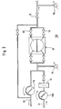
- peritoneal dialysis machine 10 in a schematic illustration.
- This peritoneal dialysis machine 10 has a source 12 for peritoneal dialysis fluid, which usually consists of a plurality of artificial tuber bags which are filled with a sterile peritoneal dialysis fluid. These bags are sterile connected to at least one inlet line 16 via a connector arrangement 14.
- the peritoneal dialysis fluid can also be prepared on-line from electrolyte concentrates and an osmotically active substance (e.g. glucose or glucose polymers) by mixing with water.
- an osmotically active substance e.g. glucose or glucose polymers
- the input line 16 extends from the source 12 or the connector arrangement 14 to a branch point 18 and there passes into a delivery line 20, which branches at its other end 21 into a first balance chamber line 22 and a second balance chamber line 24.
- Both lines 22 and 24 each open into a balancing chamber 26.
- the balancing chamber 26 essentially consists of a rigid balancing chamber housing 28 which is divided into a first balancing chamber half 32 and a second balancing chamber half 34 by a movable, liquid-impermeable membrane 30. Both balance chamber halves 32 and 34 form the actual balance chamber 26, which has a predetermined constant volume (advantageously about 20-30 ml).
- the first balancing chamber line 22 opens into the first balancing chamber half 32, while the second balancing chamber line 24 opens into the second balancing chamber half 34.
- a third balancing chamber line 36 extends from the first balancing chamber half 32 and a fourth balancing chamber line 38 branches off from the second balancing chamber half 34, which lead together to a branching point 40.
- a catheter line 42 extends from the branching point 40, the end of which can be connected to a peritoneal dialysis catheter (not shown) via a further connector arrangement 44.
- First, second, third and fourth valves are provided in the first, second, third and fourth balancing chamber lines 22, 24, 36 and 38, respectively, the first and fourth valves 46, 52 being a first pair of valves and those in the drawing second and third valves 48, 50 shown in dark represent a second pair of valves.
- the first and second valve pairs are activated in opposite directions, i.e. while the first pair of valves is closed, the second pair of valves remains open and vice versa.
- catheter line 42 is connected to a pressure detector 56, either directly on the circumference of the line or by means of a connecting line 58 which is connected to the pressure detector 56 under sterile conditions.
- This pressure detector 56 is able to exactly determine pressure differences of 0-200 mbar (negative and positive pressures).
- only one pump 60 is provided for supplying and removing the dialysis fluids. This pump 60 is switched on in the delivery line 20.
- fresh dialysis fluid is conveyed clockwise via the feed line 16 into the delivery line 20, while counter-clockwise delivery of used dialysis fluid from the delivery line 20 into a drain line 62, which goes from the branch point 18 and flows into a drain, not shown.
- a second pressure detector 64 is provided between the balance chamber 26 and the pump 60 in the area of the delivery line 20 as a device for determining the complete filling of the balance chamber 26, which is either connected directly to the delivery line 20 or via a connecting line 66 in pressure connection is.
- the pressure rises steeply when the filling of the balance chamber is reached, so that the pressure increase can be used to switch over the respective valve pairs 46, 52, 48, 50, if necessary in connection with stopping the pump.
- a heating device 72 is provided in the form of a heating bag, which, as shown in FIG. 1, is advantageously arranged between the pump 70 and the balancing chamber 26 in the delivery line 20. Heating bags of this type are known and are used to warm the peritoneal dialysis fluid to the body temperature of the patient. On the other hand, however, such a heating bag 72 can also be arranged in the feed line 16 upstream of the fifth valve 68.
- a vent line 74 extends from the catheter line 42 and opens into the drain line 62 downstream of the sixth valve 70.
- a seventh valve 76 is switched into the vent line 74.
- an eighth valve 78 can be provided in the catheter line 42 upstream of the first pressure sensor 56 and downstream of the branch point of the ventilation line 74.
- the valves are advantageously designed as electrically activatable clamps which have a clamping effect on the elastic hose wall as soon as the cassette 80 is inserted.
- the pressure sensors 56 and 64 also advantageously have a touching action on the hose wall and determine the inner hose pressure by the deformation of the hose.
- disposable sensors integrated in the hose can also be used.
- a control unit 82 is provided, which is connected to the first to eighth valves 46-52, 68, 70, 76 and 78 via the control lines 84-98.
- the control device 82 is connected to the pump 60 via a ninth control line 100. It receives signals from the first and second pressure sensors 56 and 64 via the signal lines 102 and 104.
- the peritoneal dialysis machine 10 shown in FIG. 1 is operated as follows: Fresh peritoneal dialysis fluid is first provided in the source 12. The patient is connected to the connector 44 via the peritoneal dialysis catheter. Thereafter, the peritoneal dialysis machine 10 is activated and set to run-in. After that it will Valve 68 in the inlet line 60 is opened, while the valve 70 in the outlet line 62 remains closed. The pump 60 is switched to the run-in mode, the heating for the heating bag 72 being activated at the same time.
- the control device 82 then switches the first and second valve pairs 46, 52 and 50, 48 alternately as soon as the first and second balancing chamber halves 32, 34 are filled. Due to the filling of the balance chambers 32 and 34, there is an increase in pressure in the feed line 20, 22, 24, which is determined with the sensor 64 and then used to trigger the switchover signal.
- Fresh dialysis fluid is supplied via lines 16, 20, 22 and 24 to the first balancing chamber 32 and the second balancing chamber 34, respectively.
- the other half of the balance chamber which is completely filled, is displaced towards the patient when the complementary balance chamber is filled by displacing the movable membrane 30 via the lines 36 and 38 and the catheter line 42. This creates an essentially continuous fluid delivery to the patient that is faster and gentler.
- Each changeover signal thus corresponds to a displaced part of the balancing chamber volume of dialysis fluid.
- These changeover signals are summed in the control unit 82 and, at the end of the running-in phase, result in the absolute amount of dialysis fluid supplied by multiplying by the known balance chamber volume.
- the supply pressure in the catheter line 42 is measured with the first pressure sensor 56.
- a predetermined overpressure for the supply phase for example +100 mbar, is set in the control unit 82 and must not be exceeded. Accordingly, the pumping rate at the pump 60 is controlled so that this positive limit pressure is not exceeded.
- the switchover of the balance chamber valves 46-52 can not only be determined by an increase in the pressure at the second pressure sensor 64, it can also be determined by the increase in the motor current of the pump 60. It is useful that all balance chamber valves 46-52 are kept closed for a short period of time when switching, so that the balance as a whole is not disturbed. The process of continuous switching leads to a quasi-continuous flow of the dialysis fluid through the balance chamber 26 and thus to the peritoneal catheter.
- the running-in phase is ended when the control unit 82 is correspondingly activated when a predetermined amount of dialysis fluid supplied (which can be determined by the number of cycles) or preferably after a predetermined excess pressure is exceeded at the first pressure sensor 56, if necessary at an ever decreasing delivery rate .
- the eighth valve 78 is closed, so that all other parts, valves and the pump 60 can be deactivated upstream thereof. If excess dialysis fluid or excess air should be present in the catheter feed line, these fluids can be removed into the spout via the vent line 74, the seventh valve 76 being activated for this purpose. This operation is particularly important if pressure equalization is to be created in the catheter line 42, which usually happens before the valve 78 is closed.
- the treatment phase of the patient follows, the duration of which is fixed with a timer 83, which is arranged within the control unit 82.
- valve 78 is first opened.
- the valve pairs 46 and 52 or 48 and 50 are alternately switched over again when the full filling level of the balancing chamber 26 is reached, which is determined by exceeding a predetermined negative pressure at the second pressure sensor 64.
- the used dialysis fluid is removed with the pump 60, which is switched in the direction of rotation by the control device 82 (counterclockwise).
- a negative pressure is now set at the pressure sensor 56, which is used to control the pumping rate when a predetermined value is reached.
- inlet valve 68 is closed and the outlet valve 70 is open.
- the vent valve 76 is closed in this phase.
- the used dialysis fluid is removed under pressure control by means of the first pressure sensor 56, a predetermined vacuum, for example -100 mbar, not to be undercut.
- FIG. 2 shows a second embodiment of a peritoneal dialysis machine 106, the structure of which is largely similar to that of the peritoneal dialysis machine 10 according to FIG. 1.
- the same reference numerals are used for the same parts.
- the second embodiment differs from the first embodiment only in that two pumps are used instead of a pump 60 that can be operated from both sides.
- An inlet pump 108 is provided as a peristaltic pump in the inlet line 16 upstream of the valve 68, while an outlet pump 110 is provided in the outlet line 62, which is also designed as a peristaltic roller pump.
- valves 68 and 70 according to the second embodiment do not necessarily have to be provided if the occluding peristaltic pumps 108 and 110 are used.
- the embodiment according to FIG. 2 is operated in the same way as the embodiment according to FIG. 1.
- the inlet pump 108 is activated in the run-in phase, while only the discharge pump 110 is activated in the run-out phase.
- the two pumps 108 and 110 act as hose clamp valves due to their occluding properties and thereby block the lines connected to them.
- valves are advantageously designed as pinch valves and can in some cases also be designed or switched in groups.
- One or more temperature sensors on the hose are useful for regulating and monitoring the heating.
- An air detector can also be inserted between the valve 78 and the valves 50 and 52 to increase safety.
- redundant pressure monitoring is carried out by the two pressure sensors 56 and 64, which are hydraulically coupled to one another by the lines and the balancing chamber 26. After treatment, the patient is separated from the cassette 80, which is then discarded.
Landscapes
- Health & Medical Sciences (AREA)
- Heart & Thoracic Surgery (AREA)
- Urology & Nephrology (AREA)
- Emergency Medicine (AREA)
- Anesthesiology (AREA)
- Engineering & Computer Science (AREA)
- Vascular Medicine (AREA)
- Biomedical Technology (AREA)
- Hematology (AREA)
- Life Sciences & Earth Sciences (AREA)
- Animal Behavior & Ethology (AREA)
- General Health & Medical Sciences (AREA)
- Public Health (AREA)
- Veterinary Medicine (AREA)
- External Artificial Organs (AREA)
Abstract
Description
Die Erfindung betrifft ein Peritonealdialysegerät mit einer Bilanzieranordnung mit zwei Kammern, die durch eine Ventilanordnung jeweils in eine Füll- bzw. Entleerungsphase umschaltbar sind, einer mit der Bilanzieranordnung über eine Zuführleitung verbundene Peritonealdialysierflüssigkeitsquelle, eine mit einem Peritonealkatheter verbindbaren, von der Bilanzieranordnung abgehende Katheterleitung, eine von der Bilanzieranordnung abgehende Abflußleitung, einer Pumpanordnung zur Förderung von frischer bzw. verbrauchter Peritonealdialysieflüssigkeit und einer Steuereinheit zum Steuern der Ventilanordnung und der Pumpanordnung.The invention relates to a peritoneal dialysis machine with a balancing arrangement with two chambers, each of which can be switched into a filling or emptying phase by a valve arrangement, a peritoneal dialysis fluid source connected to the balancing arrangement via a supply line, a catheter line which can be connected to a peritoneal catheter and leads away from the balancing arrangement drain line leading from the balancing arrangement, a pump arrangement for conveying fresh or used peritoneal dialysis fluid and a control unit for controlling the valve arrangement and the pump arrangement.
Vorrichtungen zur automatisierten Peritonealdialyse, nachstehend Cycler genannt, haben die Aufgabe, Peritonealdialysierflüssigkeit in definierter Menge und Temperatur in den Bauchraum eines Patienten mittels eines Verweilkatheters zu befördern und nach einer Einwirkzeit wieder zu entfernen, wobei das im Peritonealraum während der Dialysebehandlung erzeugte Ultrafiltrat zugleich mit abgezogen werden soll. Dieser Grundprozeß wiederholt sich in cyclischen Abständen entsprechend den jeweiligen klinischen Verfahren und den individuellen Erfordernissen der Behandlung.Devices for automated peritoneal dialysis, hereinafter referred to as cyclers, have the task of delivering peritoneal dialysis fluid in a defined quantity and temperature into the abdominal cavity of a patient by means of an indwelling catheter and removing it again after an exposure time, the ultrafiltrate generated in the peritoneal space during the dialysis treatment being simultaneously removed should. This basic process is repeated at cyclic intervals in accordance with the respective clinical procedures and the individual requirements of the treatment.
Die Flüssigkeit soll in möglichst kurzer Zeit in vorbestimmter Menge verabreicht und nach der Wirkzeit wiederum in möglichst kurzer Zeit entzogen werden, wobei die entzogene Menge genauer bestimmt werden muß, damit eine hinreichend genaue Aussage über die Bilanz und damit auch die Menge des körpereigenen erzeugten Ultrafiltrats gewährleistet ist. Während des Ein- und Auslaufs der Flüssigkeit darf keine Patientengefährdung oder Befindlichkeitsbeeinträchtigung entstehen. Es ist auch exakt festzustellen, wann der Bauchraum hinreichend leer ist, um den nächsten Einlauf wieder zu starten.The liquid should be administered in a predetermined amount in the shortest possible time and again removed in the shortest possible time after the effective time, the amount withdrawn having to be determined more precisely, so that a sufficiently precise statement about the balance and thus also the amount of the body's own ultrafiltrate is guaranteed. No patient risk or impairment of health may arise during the inflow and outflow of the liquid. It is also possible to determine exactly when the abdomen is sufficiently empty to start the next enema again.
Üblicherweise schließt sich der Patient selbst an einen solchen Cycler bei der Heimdialyse an. Die eigentliche Behandlung erfolgt dann teilweise während des Schlafs, so daß eine einfache Bedienbarkeit und absolute Sicherheit unabdingbar sind. Auch darf die Funktion nicht beeinträchtigt werden durch korposkulare Bestandteile der auslaufenden Flüssigkeit, die besonders bei Entzündungen im Patienten entstehen können. Schließlich muß der Flüssigkeitstransfer unter absolut sterilen Bedingungen ablaufen, da ansonsten die Gefahr der Entstehung einer zum Teil lebensbedrohlichen Peritonitis auftreten kann.The patient usually connects himself to such a cycler during home dialysis. The actual treatment then takes place partly during sleep, so that ease of use and absolute safety are essential. The function must not be impaired by corposcular components of the escaping liquid, which can arise especially in the case of inflammation in the patient. Finally, the liquid transfer must take place under absolutely sterile conditions, since otherwise there is a risk of developing a sometimes life-threatening peritonitis.
Es sind bereits eine Vielzahl von zum Teil vollautomatischen Peritonealdialysegeräten bekannt, die jedoch die vorstehend genannten Anforderungen nur zum Teil erfüllen.A large number of partially fully automatic peritoneal dialysis machines are already known, but they only partially meet the above-mentioned requirements.
Aus der Münchener Medizinischen Wochenzeitschrift (1972) S. 313 ist ein Peritonealdialysegerät bekannt, bei dem volumetrisch eine bestimmte Menge Peritonealdialysierflüssigkeit einem Patienten zugeführt wird. Nach der Dialysephase wird diese Flüssigkeit dem Patienten wieder entzogen, wobei eine Volumenbilanz erstellt werden soll. Es ist jedoch nicht ersichtlich, wie die Ultrafiltrationsmenge bestimmt werden soll.A peritoneal dialysis machine is known from the Munich Medical Weekly Magazine (1972), p. 313, in which a certain amount of peritoneal dialysis fluid is volumetrically supplied to a patient. After the dialysis phase, this liquid is withdrawn from the patient, a volume balance to be drawn up. However, it is not clear how the amount of ultrafiltration should be determined.
Aus dem US-Patent 3 709 222 ist ebenfalls ein automatisches Peritonealdialysegerät bekannt, das mit Hilfe von Proportionierungskammern in zeitabhängiger Weise Dialysierflüssigkeit einem Patienten zuführt. Eine volumetrische Kontrolle der geförderten Flüssigkeiten ist mit dieser Anordnung nicht zu erreichen, da dort expandierbare Kammern, beispielsweise die Rücklaufkammer in Verbindung mit wegabhängigen Sensoren, eingesetzt werden, so daß keine genaue volumetrische Kontrolle gegeben ist.An automatic peritoneal dialysis device is also known from US Pat. No. 3,709,222, which supplies dialysis fluid to a patient in a time-dependent manner with the aid of proportioning chambers. With this arrangement, a volumetric control of the conveyed liquids is possible cannot be achieved, since expandable chambers, for example the return chamber in connection with path-dependent sensors, are used, so that no precise volumetric control is given.
Weitere Peritonealdialysegeräte sind in den US-Patenten 4 096 859, 4 412 917, 4 381 003, und 5 004 459 beschrieben. Bei den Geräten gemäß der beiden zuerst genannten US-Patentschriften werden Wägevorrichtungen eingesetzt, die schwierig zu handhaben sind und daher für einen möglichst einfach zu gestaltenden Cycler bereits aus Handhabungsgründen nicht in Frage kommen. Auch die Vorrichtungen gemäß den anderen US-Patenten sind mit Mängeln behaftet, da diese peristaltische Pumpen einsetzen, deren Förderraten bekanntlich vom Eingangsdruck abhängen. Da diese Eingangsdrücke in Abhängigkeit von der Förderart stark variieren, sind solche Pumpanordnungen mit erheblichen volumetrischen Fehlern behaftet, so daß ein Einsatz bei der Ultrafiltrationskontrolle in der Peritonealdialyse hiermit nicht verwirklicht werden kann.Additional peritoneal dialysis machines are described in U.S. Patents 4,096,859, 4,412,917, 4,381,003, and 5,004,459. In the devices according to the two first-mentioned US patents, weighing devices are used which are difficult to handle and are therefore out of the question for a cycler which is as simple to design as possible, for handling reasons alone. The devices according to the other US patents are also defective because they use peristaltic pumps, the delivery rates of which depend, as is known, on the inlet pressure. Since these inlet pressures vary greatly depending on the type of delivery, such pump arrangements are subject to considerable volumetric errors, so that use in ultrafiltration control in peritoneal dialysis cannot be achieved with them.
Schließlich beschreibt die EP-A 149 001 ein Peritonealdialysegerät, bei dem die Dialysierflüssigkeit in einem extrakorporalen Kreislauf durch die semipermeable Membran eines Filters hinweg dem Katheter des Patienten zugeführt wird. Obwohl diese Vorrichtung vollautomatisch teils gesteuert, teils geregelt arbeitet, ist diese zu aufwendig und damit auch schwierig zu betreiben, ganz abgesehen davon, daß die dort eingesetzten Disposables zu teuer sind. Das gleiche gilt bei den aus dem DE-G 87 14 464 bekannten Disposable.Finally, EP-A 149 001 describes a peritoneal dialysis machine in which the dialysis fluid is supplied to the patient's catheter in an extracorporeal circuit through the semipermeable membrane of a filter. Although this device operates fully automatically partly controlled, partly regulated, it is too complex and therefore difficult to operate, quite apart from the fact that the disposables used there are too expensive. The same applies to the disposable known from DE-G 87 14 464.
Schließlich sind in der Hämodialyse exakt bilanzierende Systeme bekannt, bei denen frische und verbrauchte Dialysierflüssigkeit gegeneinander im geschlossenen Kreislauf in einer Bilanzkammer stetig bilanziert werden.Finally, exactly balancing systems are known in hemodialysis, in which fresh and used dialysis fluid are constantly balanced against each other in a closed circuit in a balancing chamber.
Der Erfindung liegt daher die Aufgabe zugrunde, ein Peritonealdialysegerät der eingangs erwähnten Art zur Verfügung zu stellen, das in einfacher und zuverlässiger Weise eine genaue Volumenbestimmung der zu- und abgeführten Peritonealdialysierflüssigkeiten ermöglicht.The invention is therefore based on the object of providing a peritoneal dialysis machine of the type mentioned at the outset which, in a simple and reliable manner, enables precise volume determination of the peritoneal dialysis fluids supplied and discharged.
Die Aufgabe wird dadurch gelöst, daß das Peritonealdialysegerät eine einzige Bilanzkammer aufweist, die durch eine bewegliche, flüssigkeitsundurchlässige Membran in zwei Bilanzkammerhälften getrennt ist, wobei die Bilanzkammerhälften wechselweise über die Ventilanordnung einerseits mit der Quelle für die Peritonealdialysierflüssigkeit im Zuförderbetrieb und mit der Abflußleitung im Abförderbetrieb und andererseits mit der Katheterleitung in Strömungsverbindung sind, ein erster Drucksensor an der Katheterleitung angeordnet ist, auf dessen druckabhängiges Signal die Steuereinheit bei Erreichen eines vorgegebenen Druckwerts die Pumpe inaktiviert, und eine Einrichtung zum Ermitteln der vollständigen Füllung der Bilanzkammer vorgesehen ist, auf deren Signal hin die Steuereinheit die Ventilanordnung jeweils zyklisch umschaltet.The object is achieved in that the peritoneal dialysis machine has a single balancing chamber which is separated into two balancing chamber halves by a movable, liquid-impermeable membrane, the balancing chamber halves alternately via the valve arrangement on the one hand with the source for the peritoneal dialysis fluid in the feed mode and with the drain line in the discharge mode and on the other hand, are in flow connection with the catheter line, a first pressure sensor is arranged on the catheter line, on the pressure-dependent signal of which the control unit inactivates the pump when a predetermined pressure value is reached, and a device is provided for determining the complete filling of the balance chamber, on the signal of which the Control unit switches the valve arrangement cyclically.
Das erfindungsgemäße Peritonealdialysegerät verfügt über eine Bilanzkammer, die durch eine bewegliche, flüssigkeitsundurchlässige Wand in zwei Hälften geteilt ist. Dabei verdrängt die in einer Hälfte zugeführte Flüssigkeitsmenge durch Verdrängung der Wand die in der anderen Hälfte vorhandene Flüssigkeitsmenge in exakt volumetrischer Weise. Infolgedessen kann mit hoher Genauigkeit das ein- oder auslaufende Volumen bis auf ein Kammervolumen genau (ca. 1% Fehler) bestimmt werden, so daß auch die ultrafiltrierte Menge exakt ermittelt werden kann. Dies hat eine bessere Kontrolle der Behandlung zur Folge bzw. die Dialysebehandlung kann hierdurch optimiert werden. Im übrigen wird eine Patientenschädigung durch Überfüllung mittels Druckkontrolle sicher vermieden.The peritoneal dialysis device according to the invention has a balancing chamber which is divided into two halves by a movable, liquid-impermeable wall. By displacing the wall, the amount of liquid supplied in one half displaces the amount of liquid present in the other half in an exactly volumetric manner. As a result, the incoming or outgoing volume can be determined with high accuracy down to a chamber volume (approx. 1% error), so that the ultrafiltered amount can also be determined exactly. This results in better control of the treatment or the dialysis treatment can be optimized as a result. Otherwise, patient damage caused by overfilling with pressure control is reliably avoided.
Das Füllen und Entleeren läßt sich in physiologisch kürzester Zeit dadurch durchführen, daß der Ein- und Auslaufdruck gesteuert überwacht wird. So läßt sich beispielsweise ein relativer Über- oder Unterdruck von 100 mbar ohne Probleme überwachen.The filling and emptying can be carried out in a physiologically short time by monitoring the inlet and outlet pressure in a controlled manner. For example, a relative positive or negative pressure of 100 mbar can be monitored without problems.
Infolgedessen läßt sich eine definierte Behandlung weitgehend unabhängig von der Lage und von der Bewegung des Patienten durchführen, so daß ihm dadurch Restriktionen erspart werden. Die Genauigkeit und Zuverlässigkeit des Systems ist unabhängig von Verschmutzungen (Blut etc.).As a result, a defined treatment can be carried out largely independently of the position and the movement of the patient, so that the patient is spared restrictions. The accuracy and reliability of the system is independent of contamination (blood, etc.).
Ein besonderer Vorteil der Erfindung ist die Tatsache, daß die Bilanzkammer einschließlich sämtlicher Schlauchzuleitungen als geschlossenes, unbelüftetes Einmal-Gebrauchssystem mit hoher Sterilitätssicherheit ausgebildet ist, wobei sämtliche Teile vorteilhafterweise aus polymeren Materialien bestehen. Eine solche Bilanzkammer ist beispielsweise in der DE-A 41 16 178 beschrieben, die jedoch bei der Hämofiltration eingesetzt wird.A particular advantage of the invention is the fact that the balancing chamber, including all hose feed lines, is designed as a closed, non-ventilated, single-use system with high sterility security, all parts advantageously being made of polymeric materials. Such a balancing chamber is described, for example, in DE-A 41 16 178, which is, however, used in hemofiltration.
Es ist weiterhin vorteilhaft, wenn dieses Einmal-Gebrauchssystem in Form einer kompakten, einfach handhabbaren Kassette vorliegt, die auf einem entsprechend ausgebildeten Basisgerät jeweils vor der Behandlung anzuordnen ist. Dieses Basisgerät enhält dann die weiteren Betriebsteile, wie Pumpen, Schlauchventile, Drucksensoren und dergleichen.It is also advantageous if this single-use system is in the form of a compact, easy-to-use cassette which is to be arranged on a suitably designed basic device before the treatment. This basic device then contains the other operating parts, such as pumps, hose valves, pressure sensors and the like.
Es zeigen
- Fig. 1
- eine erste Ausführungsform eines Peritonealdialysegeräts in schematischer Darstellung und
- Fig. 2
- eine zweite Ausführungsform eines Peritonealdialysegeräts ebenfalls in schematischer Darstellung.
- Fig. 1
- a first embodiment of a peritoneal dialysis machine in a schematic representation and
- Fig. 2
- a second embodiment of a peritoneal dialysis machine also in a schematic representation.
In Fig. 1 ist ein Peritonealdialysegerät 10 in schematischer Darstellung gezeigt. Dieses Peritonealdialysegerät 10 weist eine Quelle 12 für Peritonealdialysierflüssigkeit auf, die üblicherweise aus einer Mehrzahl von Kunststollbeuteln besteht, die mit einer sterilen Peritonealdialysierflüssigkeit gefüllt sind. Diese Beutel sind über eine Konnektoranordnung 14 steril mit mindestens einer Einlaufleitung 16 verbunden. Andererseits kann jedoch aber auch die Peritonealdialysierflüssigkeit on-line aus Elektrolytkonzentraten und einer osmotisch wirksamen Substanz (z.B. Glucose oder Glucosepolymere) durch Vermischen mit Wasser hergestellt werden. Eine derartige Anlage ist ebenfalls unter der Quelle 12 zu verstehen.1 shows a
Die Eingangsleitung 16 erstreckt sich von der Quelle 12 bzw. der Konnektoranordnung 14 bis zu einem Verzweigungspunkt 18 und geht dort in eine Förderleitung 20 über, die sich an ihrem anderen Ende 21 in eine erste Bilanzkammerleitung 22 und in eine zweite Bilanzkammerleitung 24 verzweigt.The
Beide Leitungen 22 und 24 münden jeweils in eine Bilanzkammer 26.Both
Die Bilanzkammer 26 besteht im wesentlichen aus einem starren Bilanzkammergehäuse 28, die durch eine bewegliche, flüssigkeitsundurchlässige Membran 30 in eine erste Bilanzkammerhälfte 32 und in eine zweite Bilanzkammerhälfte 34 unterteilt ist. Beide Bilanzkammerhälften 32 und 34 bilden dabei die eigentliche Bilanzkammer 26, die ein vorgegebenes konstantes Volumen (vorteilhafterweise etwa 20-30 ml) aufweist.The
Wie aus Fig. 1 ersichtlich ist, mündet die erste Bilanzkammerleitung 22 in die erste Bilanzkammerhälfte 32, während die zweite Bilanzkammerleitung 24 in die zweite Bilanzkammerhälfte 34 mündet.1, the first
Von der ersten Bilanzkammerhälfte 32 geht eine dritte Bilanzkammerleitung 36 und von der zweiten Bilankammerhälfte 34 geht eine vierte Bilanzkammerleitung 38 ab, die gemeinsam in einem Verzweigungspunkt 40 münden.A third
Vom Verzweigungspunkt 40 erstreckt sich eine Katheterleitung 42, deren Ende über eine weitere Konnektoranordnung 44 mit einem Peritonealdialysekatheter (nicht gezeigt) verbunden werden kann.A
In der ersten, zweiten, dritten bzw. vierten Bilanzkammerleitung 22, 24, 36 bzw. 38 sind jeweils erste, zweite, dritte bzw. vierte Ventile vorgesehen, wobei das erste und das vierte Ventil 46, 52 ein erstes Ventilpaar und die in der Zeichnung dunkel dargestellten zweiten und dritten Ventile 48, 50 ein zweites Ventilpaar darstellen. Erfindungsgemäß werden dabei die ersten und zweiten Ventilpaare gegenläufig aktiviert, d.h. während das erste Ventilpaar geschlossen ist, bleibt das zweite Ventilpaar geöffnet und umgekehrt.First, second, third and fourth valves are provided in the first, second, third and fourth
Weiterhin ist die Katheterleitung 42 mit einem Druckdetektor 56 verbunden, und zwar entweder direkt am Leitungsumfang oder aber mittels einer Verbindungsleitung 58, die unter sterilen Bedingungen mit dem Druckdetektor 56 verbunden ist. Dieser Druckdetektor 56 ist in der Lage, Druckunterschiede von 0-200 mbar (Unter- wie Überdrücke) exakt zu bestimmen.Furthermore, the
Gemäß der in Fig. 1 gezeigten Ausführungsform ist nur eine Pumpe 60 zur Zu- und Abförderung der Dialysierflüssigkeiten vorgesehen. Diese Pumpe 60 ist in die Förderleitung 20 eingeschaltet.According to the embodiment shown in FIG. 1, only one
Wie aus Fig. 1 ersichtlich ist, erfolgt im Uhrzeigersinn eine Förderung von frischer Dialysierflüssigkeit über die Zuleitung 16 in die Förderleitung 20, während gegen den Uhrzeigersinn die Abförderung gebrauchter Dialysierflüssigkeit aus der Förderleitung 20 in eine Abflußleitung 62 erfolgt, die vom Verzweigungspunkt 18 abgeht und in einen nicht gezeigten Abfluß mündet.As can be seen from FIG. 1, fresh dialysis fluid is conveyed clockwise via the
Zwischen Bilanzkammer 26 und der Pumpe 60 ist gemäß einer ersten Ausführungsform im Bereich der Förderleitung 20 ein zweiter Druckdetektor 64 als Einrichtung zur Ermittlung der vollständigen Füllung der Bilanzkammer 26 vorgesehen, der entweder unmittelbar mit der Förderleitung 20 verbunden ist oder aber über eine Verbindungsleitung 66 in Druckverbindung ist. Bekanntlich steigt der Druck steil mit Erreichen der Füllung der Bilanzkammer an, so daß der Druckanstieg zum Umschalten der jeweiligen Ventilpaare 46,52;48,50 ggf. in Verbindung mit einem Stillsetzen der Pumpe herangezogen werden kann.According to a first embodiment, a
Die in Fig. 1 gezeigte erste Ausführungsform eines Peritonealdialysegerätes 10, die nur über eine Pumpe 60 verfügt, weist vorteilhafterweise in der Einlaufleitung 16 ein fünftes Ventil 68 und in der Abflußleitung 62 ein sechstes Ventil 70 auf, die ebenfalls gegensinnig betätigt werden.The first embodiment of a
Des weiteren ist eine Heizeinrichtung 72 in Form eines Heizungsbeutels vorgesehen, der, wie in Fig. 1 dargestellt ist, vorteilhafterweise zwischen der Pumpe 70 und der Bilanzkammer 26 in der Förderleitung 20 angeordnet ist. Derartige Heizungsbeutel sind bekannt und dienen zum Aufwärmen der Peritonealdialysierflüssigkeit auf die Körpertemperatur des Patienten. Andererseits kann jedoch aber auch ein solcher Heizungsbeutel 72 in der Zulaufleitung 16 stromauf des fünften Ventils 68 angeordnet sein.Furthermore, a
Zu Entlüftungszwecken bzw. zum Druckausgleich geht von der Katheterleitung 42 eine Entlüftungsleitung 74 ab, die in die Abflußleitung 62 stromab des sechsten Ventils 70 mündet. In die Entlüfüngsleitung 74 ist ein siebtes Ventil 76 eingeschaltet.For venting purposes or for pressure compensation, a
Schließlich kann in der Kathetherleitung 42 stromauf des ersten Drucksensors 56 und stromab des Abzweigpunktes der Entlüftungsleitung 74 ein achtes Ventil 78 vorgesehen sein.Finally, an
Sämtliche in Fig. 1 gezeigten Leitungen, die mit der Bilanzkammer 26 verbunden sind, bestehen wie die Bilanzkammer 26 selbst und der Heizbeutel 72 aus polymeren Materialien. Sämtliche Komponenten sind gemäß einer weiteren Ausführungsform in vorbestimmter Lage in einer üblicherweise ebenfalls aus Kunststoff bestehenden Kassette 80 angeordnet, die in Fig. 1 gestrichelt dargestellt ist. Die Ventile wiederum sind vorteilhafterweise als elektrisch aktivierbare Klemmen ausgebildet, die auf die elastische Schlauchwand klemmend einwirken, sobald die Kassette 80 eingelegt ist. Auch die Drucksensoren 56 und 64 wirken vorteilhafterweise berührend auf die Schlauchwand ein und bestimmen den Schlauchinnendruck durch die Verformung des Schlauchs. Andererseits sind jedoch aber auch in den Schlauch integrierte Einmalsensoren einsetzbar.All of the lines shown in FIG. 1, which are connected to the balancing
Zur Steuerung des Peritonealdialysegerätes 10 ist eine Steuereinheit 82 vorgesehen, die über die Steuerleitungen 84-98 mit den ersten bis achten Ventilen 46-52, 68, 70, 76 bzw. 78 verbunden sind. Über eine neunte Steuerleitung 100 ist die Steuereinrichtung 82 mit der Pumpe 60 verbunden. Sie empfängt Signale von dem ersten bzw. zweiten Drucksensor 56 bzw. 64 über die Signalleitungen 102 bzw 104.To control the
Das in Fig. 1 gezeigte Peritonealdialysegerät 10 wird folgendermaßen betrieben:
In der Quelle 12 wird zunächst frische Peritonealdialysierflüssigkeit bereitgestellt. Der Patient wird über den Peritonealdialysekatheter an die Konnektionseinrichtung 44 angeschlossen. Danach wird das Peritonealdialysegerät 10 aktiviert und auf Einlauf gestellt. Hiernach wird das Ventil 68 in der Einlaufleitung 60 geöffnet, während das Ventil 70 in der Auslaufleitung 62 geschlossen bleibt. Die Pumpe 60 wird in den Einlaufbetrieb geschaltet, wobei gleichzeitig die Heizung für den Heizbeutel 72 aktiviert wird.The
Fresh peritoneal dialysis fluid is first provided in the
Die Steuereinrichtung 82 schaltet anschließend die ersten und zweiten Ventilpaare 46, 52 bzw. 50, 48 alternierend, sobald die erste bzw. zweite Bilanzkammerhälfte 32, 34 gefüllt ist. Durch die Füllung der Bilanzkammern 32 bzw. 34 erfolgt ein Druckanstieg in der Zuführungsleitung 20, 22, 24, der mit dem Senor 64 ermittelt und dann zur Auslösung des Umschaltsignals herangezogen wird.The
Frische Dialysierflüssigkeit wird über die Leitungen 16, 20, 22 bzw. 24 der ersten Bilanzkammer 32 bzw. der zweiten Bilanzkammer 34 zugeführt. Die jeweils andere Bilanzkammerhälfte, die vollständig gefüllt ist, wird bei dem Füllen der komplementären Bilanzkammer durch Verdrängen der bewegbaren Membran 30 über die Leitung 36 bzw. 38 und die Katheterleitung 42 zum Patienten hin verdrängt. Dadurch wird eine im wesentlichen kontinuierliche Flüssigkeitsförderung zum Patienten erzeugt, die schneller und schonender ist.Fresh dialysis fluid is supplied via
Jedes Umschaltsignal entspricht also einem verdrängten Bilanzkammervolumenteil Dialysierflüssigkeit. Diese Umschaltsignale werden in der Steuereinheit 82 summiert und ergeben am Ende der Einlaufphase durch Multiplikation mit dem bekannten Bilanzkammervolumen die absolut zugeführte Dialysierflüssigkeitsmenge.Each changeover signal thus corresponds to a displaced part of the balancing chamber volume of dialysis fluid. These changeover signals are summed in the
Mit dem ersten Drucksensor 56 wird dabei der Zuführungsdruck in der Katheterleitung 42 gemessen. In der Steuereinheit 82 ist ein vorgegebener Überdruck für die Zuführungsphase, beispielsweise +100 mbar festgelegt, der nicht überschritten werden darf. Demzufolge wird also die Pumprate an der Pumpe 60 so geregelt, daß dieser positive Grenzdruck nicht überschritten wird.The supply pressure in the
Hierdurch wird eine Befüllung in kürzestmöglicher, physiologisch verträglicher Zeit erreicht, ohne daß gefährliche Überdrucksituationen auftreten können.As a result, filling is achieved in the shortest possible, physiologically compatible time, without dangerous overpressure situations being able to occur.
Die Umschaltung der Bilanzkammerventile 46-52 kann nicht nur durch Anstieg des Drucks an dem zweiten Drucksensor 64 bestimmt werden, sie kann auch durch den Motorstromanstieg der Pumpe 60 ermittelt werden. Zweckmäßig ist es dabei, daß beim Umschalten alle Bilanzkammerventile 46-52 für eine kurze Zeitspanne geschlossen gehalten werden, so daß die Bilanz insgesamt nicht gestört wird. Der Vorgang der fortlaufenden Umschaltung führt dabei zu einem quasi-kontinuierlichen Fluß der Dialysierflüssigkeit durch die Bilanzkammer 26 und damit zum Peritonealkatheter.The switchover of the balance chamber valves 46-52 can not only be determined by an increase in the pressure at the
Die Einlaufphase wird dann beendet, wenn die Steuereinheit 82 bei Erreichen einer vorgegebenen zugeführten Dialysierflüssigkeitsmenge (was durch die Zahl der Zyklen festgestellt werden kann) oder vorzugsweise nach Überschreiten eines vorbestimmten Überdrucks an dem ersten Drucksensor 56 ggf. bei einer immer geringer werdenden Förderraterate entsprechend aktiviert wird.The running-in phase is ended when the
Am Ende der Einlaufphase wird das achte Ventil 78 geschlossen, so daß stromauf hiervon sämtliche übrigen Teile, Ventile und die Pumpe 60 desaktiviert werden können. Sofern überschüssige Dialysierflüssigkeit oder überschüssige Luft in der Katheterzuleitung vorhanden sein sollten, können diese Fluide über die Entlüftungsleitung 74 in den Ausguß entfernt werden, wobei hierzu das siebte Ventil 76 aktiviert wird. Diese Operation ist insbesondere dann wichtig, wenn ein Druckausgleich in der Katheterleitung 42 geschaffen werden soll, was üblicherweise vor Schließen des Ventils 78 geschieht.At the end of the running-in phase, the
Nach der Einlaufphase folgt die Behandlungsphase des Patienten, deren Dauer mit einem Zeitglied 83, das innerhalb der Steuereinheit 82 angeordnet ist, festgelegt ist.After the running-in phase, the treatment phase of the patient follows, the duration of which is fixed with a
Nach Ablauf dieses Peritonealdialysezyklus wird das Peritonealdialysegerät 10 in die Auslaufphase geschaltet. Hierzu wird zunächst das Ventil 78 geöffnet. Des gleichen werden die Ventilpaare 46 und 52 bzw. 48 und 50 wieder alternierend bei Erreichen des vollständigen Füllgrades der Bilanzkammer 26, was durch Überschreiten eines vorbestimmten Unterdrucks am zweiten Drucksensor 64 festgestellt wird, umgeschaltet. Die Abförderung der gebrauchten Dialysierflüssigkeit erfolgt mit der Pumpe 60, die durch das Steuergerät 82 in ihrem Drehsinn umgeschaltet wird (gegen den Uhrzeigersinn).After this peritoneal dialysis cycle has ended, the
Nachdem sich die Pumpe 60 im Saugbetrieb befindet, stellt sich am Drucksensor 56 nunmehr ein Unterdruck ein, der bei Erreichen eines vorbestimmten Wertes zur Regelung der Pumprate herangezogen wird.After the
Des weiteren ist das Einlaufventil 68 geschlossen und das Auslaufventil 70 geöffnet. Das Entlüftungsventil 76 ist in dieser Phase geschlossen.Furthermore, the
Die Abförderung der gebrauchten Dialysierflüssigkeit erfolgt unter Druckkontrolle mittels des ersten Drucksensors 56, wobei ein vorbestimmter Unterdruck, beispielsweise -100 mbar, nicht unterschritten werden darf.The used dialysis fluid is removed under pressure control by means of the
Zunächst herrscht jedoch im Peritonealraum ein leichter Überdruck, so daß gebrauchte Dialysierflüssigkeit mit einer relativ hohen Entnahmerate entnommen werden kann. Am Ende der Auslaufrate steigt der Unterdruck an, so daß bei Erreichen des vorbestimmten Grenzwertes die Pumprate schrittweise zurückgenommen wird. Es kommt dann zu einer Zurückregelung der Fördermenge so lange, bis die Pumpe zum Stillstand kommt bzw. eine sehr geringe, vorgegebene Förderrate erreicht wird oder ein Bilanzkammerzyklus in dieser Phase abgeschlossen ist.First of all, however, there is a slight overpressure in the peritoneal space, so that used dialysis fluid can be removed at a relatively high removal rate. At the end of the outflow rate, the vacuum rises, so that the pumping rate is gradually reduced when the predetermined limit value is reached. The flow rate is then reduced until the pump comes to a standstill or very low, predetermined delivery rate is reached or a balancing chamber cycle is completed in this phase.
Dies ist ein Signal für das Ende der Entleerphase. Es werden dann wieder sämtliche Bilanzkammerhübe summiert und die gesamte Menge an entzogener Dialysierflüssigkeit bestimmt. Die Differenz zwischen zugeführter und abgeführter Flüssigkeitsmenge gibt dann die dem Patienten durch Ultrafiltration entzogene Flüssigkeitsmenge.This is a signal for the end of the emptying phase. All balancing chamber strokes are then totaled again and the total amount of dialyzing fluid withdrawn is determined. The difference between the amount of liquid supplied and the amount removed then gives the amount of liquid withdrawn from the patient by ultrafiltration.
Am Ende dieser Phase wird die gesamte Anordnung gegenüber der Umgebung belüftet, wobei das Ventil 76 geöffnet wird. Sämtliche anderen Aggregate sind dabei desaktiviert. Anschließend wird das Ventil 78 geschlossen.At the end of this phase, the entire arrangement is ventilated from the surroundings, the
Danach erfolgt wiederum die Einleitung der Einlaufphase.Then the running-in phase is initiated again.
In Fig. 2 ist eine zweite Ausführungsform eines Peritonealdialysegerätes 106 gezeigt, die in ihrem Aufbau dem Peritonealdialysegerät 10 gemäß Fig. 1 weitgehend ähnlich ist. Insofern werden für gleiche Teile die gleichen Bezugszeichen verwandt.FIG. 2 shows a second embodiment of a
Die zweite Ausführungsform unterscheidet sich gegenüber der ersten Ausführungsform lediglich dadurch, daß anstelle einer beiseitig betreibbaren Pumpe 60 zwei Pumpen eingesetzt werden. Dabei ist in der Zulaufleitung 16 stromauf des Ventils 68 eine Einlaufpumpe 108 als Peristaltikpumpe vorgesehen, während in der Auslaufleitung 62 eine Auslaufpumpe 110 vorgesehen ist, die ebenfalls als peristaltische Rollenpumpe ausgestaltet ist.The second embodiment differs from the first embodiment only in that two pumps are used instead of a
Hinzuzufügen ist, daß die Ventile 68 und 70 gemäß der zweiten Ausführungsform nicht notwendigerweise vorgesehen sein müssen, sofern die okkludierend wirkenden Peristaltikpumpen 108 und 110 eingesetzt werden..It should be added that the
Die Ausführungsform gemäß Fig. 2 wird in gleicher Weise wie die Ausführungsform gemäß Fig. 1 betrieben. Dabei wird in der Einlaufphase die Einlaufpumpe 108 aktiviert, während in der Auslaufphase nur die Auslaufpumpe 110 aktiviert ist. Die beiden Pumpen 108 und 110 wirken, wenn sie stillgesetzt sind, aufgrund ihrer okkludierenden Eigenschaften dabei als Schlauchklemmventile und sperren dabei die mit ihnen verbundenen Leitungen.The embodiment according to FIG. 2 is operated in the same way as the embodiment according to FIG. 1. The
Sämtliche Ventile sind vorteilhafterweise als Klemmventile asgeführt und können teilweise auch in Gruppen ausgeführt oder geschaltet sein.All of the valves are advantageously designed as pinch valves and can in some cases also be designed or switched in groups.
Zur Regelung und Überwachung der Heizung sind ein oder mehrere Temperatursensoren am Schlauch zweckmäßig. Auch kann ein Luftdetektor zwischen dem Ventil 78 und den Ventilen 50 und 52 zur Erhöhung der Sicherheit eingefügt sein.One or more temperature sensors on the hose are useful for regulating and monitoring the heating. An air detector can also be inserted between the
Gemäß einer weiteren vorteilhaften Ausführungsform erfolgt eine redundante Drucküberwachung durch die beiden Drucksensoren 56 und 64, die hydraulisch durch die Leitungen und die Bilanzkammer 26 miteinander gekoppelt sind. Nach der Behandlung wird der Patient von der Kassette 80 abgetrennt, die danach verworfen wird.According to a further advantageous embodiment, redundant pressure monitoring is carried out by the two
Claims (12)
eine von der ersten Bilanzkammerhälfte (32) abgehenden dritten Bilanzkammerleitung (36) und eine von der zweiten Bilanzkammerhälfte (34) abgehenden vierten Bilanzkammerleitung (38), die jeweils in einem zweiten Verbindungspunkt (40) münden, von dem eine Katheterleitung (42) abgeht, deren Ende mit einem Peritonealkatheter verbindbar ist, und einem ersten, zweiten, dritten bzw. vierten Ventil (46-52), die in die erste, zweite, dritte bzw. vierte Bilanzkammerleitung (22,24,36,38) eingeschaltet sind.Peritoneal dialysis machine according to claim 1, characterized by an inlet line (14) leading from the dialysis fluid source (12), which leads to a first branch point (18), a drain line (62) leading from the first branch point (18) and into a drain opens, a delivery line (20) extending from the first branching point (18), the end of which branches into a first balance chamber line (22) and a second balance chamber line (24), the first balance chamber line (22) with the first balance chamber half (32) and the second balancing chamber line (24) is in flow connection with the second balancing chamber half (34),
a third balance chamber line (36) extending from the first balance chamber half (32) and one from the second balance chamber half (34) outgoing fourth balancing chamber line (38), each opening into a second connection point (40), from which a catheter line (42) leads, the end of which can be connected to a peritoneal catheter, and a first, second, third and fourth valve ( 46-52), which are connected to the first, second, third and fourth balancing chamber line (22,24,36,38).
Applications Claiming Priority (2)
| Application Number | Priority Date | Filing Date | Title |
|---|---|---|---|
| DE4421126A DE4421126A1 (en) | 1994-06-16 | 1994-06-16 | Peritoneal dialysis machine |
| DE4421126 | 1994-06-16 |
Publications (1)
| Publication Number | Publication Date |
|---|---|
| EP0687474A1 true EP0687474A1 (en) | 1995-12-20 |
Family
ID=6520786
Family Applications (1)
| Application Number | Title | Priority Date | Filing Date |
|---|---|---|---|
| EP95109001A Withdrawn EP0687474A1 (en) | 1994-06-16 | 1995-06-12 | Apparatus for peritoneal dialysis |
Country Status (4)
| Country | Link |
|---|---|
| US (1) | US5542919A (en) |
| EP (1) | EP0687474A1 (en) |
| JP (1) | JPH08164201A (en) |
| DE (1) | DE4421126A1 (en) |
Cited By (35)
| Publication number | Priority date | Publication date | Assignee | Title |
|---|---|---|---|---|
| EP0956876A1 (en) * | 1998-04-01 | 1999-11-17 | Fresenius Medical Care Deutschland GmbH | Cassette for the delivery of fluids, especially dialysis fluids |
| US6657982B1 (en) | 1996-12-30 | 2003-12-02 | At&T Corp. | Method and apparatus for providing high speed services using a wireless communications system |
| WO2008106538A3 (en) * | 2007-02-27 | 2009-02-12 | Deka Products Lp | Cassette system integrated apparatus |
| US7794141B2 (en) | 2006-04-14 | 2010-09-14 | Deka Products Limited Partnership | Thermal and coductivity sensing systems, devices and methods |
| US7901376B2 (en) | 2007-07-05 | 2011-03-08 | Baxter International Inc. | Dialysis cassette having multiple outlet valve |
| WO2011038858A1 (en) * | 2009-09-29 | 2011-04-07 | Fresenius Medical Care Deutschland Gmbh | Device for dialysis treatment and method for balancing fresh and used dialysis liquid |
| US8042563B2 (en) | 2007-02-27 | 2011-10-25 | Deka Products Limited Partnership | Cassette system integrated apparatus |
| US8197439B2 (en) | 2008-01-23 | 2012-06-12 | Deka Products Limited Partnership | Fluid volume determination for medical treatment system |
| US8246826B2 (en) | 2007-02-27 | 2012-08-21 | Deka Products Limited Partnership | Hemodialysis systems and methods |
| US8357298B2 (en) | 2007-02-27 | 2013-01-22 | Deka Products Limited Partnership | Hemodialysis systems and methods |
| US8366316B2 (en) | 2006-04-14 | 2013-02-05 | Deka Products Limited Partnership | Sensor apparatus systems, devices and methods |
| US8393690B2 (en) | 2007-02-27 | 2013-03-12 | Deka Products Limited Partnership | Enclosure for a portable hemodialysis system |
| US8409441B2 (en) | 2007-02-27 | 2013-04-02 | Deka Products Limited Partnership | Blood treatment systems and methods |
| US8425471B2 (en) | 2007-02-27 | 2013-04-23 | Deka Products Limited Partnership | Reagent supply for a hemodialysis system |
| US8469545B2 (en) | 2007-07-05 | 2013-06-25 | Baxter Healthcare Inc. | Peritoneal dialysis connection system and method for using ultraviolet light emitting diodes |
| US8491184B2 (en) | 2007-02-27 | 2013-07-23 | Deka Products Limited Partnership | Sensor apparatus systems, devices and methods |
| US8540886B2 (en) | 2008-08-18 | 2013-09-24 | Fresenius Medical Care Deutschland Gmbh | Dialysis cassettes and related systems and methods |
| US8562834B2 (en) | 2007-02-27 | 2013-10-22 | Deka Products Limited Partnership | Modular assembly for a portable hemodialysis system |
| US8708950B2 (en) | 2010-07-07 | 2014-04-29 | Deka Products Limited Partnership | Medical treatment system and methods using a plurality of fluid lines |
| US8771508B2 (en) | 2008-08-27 | 2014-07-08 | Deka Products Limited Partnership | Dialyzer cartridge mounting arrangement for a hemodialysis system |
| US9028691B2 (en) | 2007-02-27 | 2015-05-12 | Deka Products Limited Partnership | Blood circuit assembly for a hemodialysis system |
| US9078971B2 (en) | 2008-01-23 | 2015-07-14 | Deka Products Limited Partnership | Medical treatment system and methods using a plurality of fluid lines |
| US9517295B2 (en) | 2007-02-27 | 2016-12-13 | Deka Products Limited Partnership | Blood treatment systems and methods |
| US9586003B2 (en) | 2007-07-05 | 2017-03-07 | Baxter International Inc. | Medical fluid machine with supply autoconnection |
| US9597442B2 (en) | 2007-02-27 | 2017-03-21 | Deka Products Limited Partnership | Air trap for a medical infusion device |
| WO2017092870A1 (en) * | 2015-12-02 | 2017-06-08 | Fresenius Medical Care Deutschland Gmbh | Method for testing the rigidity of a disposable |
| US9724458B2 (en) | 2011-05-24 | 2017-08-08 | Deka Products Limited Partnership | Hemodialysis system |
| US9861732B2 (en) | 2011-11-04 | 2018-01-09 | Deka Products Limited Partnership | Medical treatment system and methods using a plurality of fluid lines |
| US10201650B2 (en) | 2009-10-30 | 2019-02-12 | Deka Products Limited Partnership | Apparatus and method for detecting disconnection of an intravascular access device |
| US10293091B2 (en) | 2007-07-05 | 2019-05-21 | Baxter International Inc. | Dialysis system having an autoconnection mechanism |
| US10537671B2 (en) | 2006-04-14 | 2020-01-21 | Deka Products Limited Partnership | Automated control mechanisms in a hemodialysis apparatus |
| EP3730166A1 (en) * | 2003-11-05 | 2020-10-28 | Baxter International Inc | Renal failure therapy machine |
| AU2020281072B2 (en) * | 2007-02-27 | 2021-01-28 | Deka Products Limited Partnership | Cassette system integrated apparatus |
| US11524103B2 (en) | 2003-11-05 | 2022-12-13 | Baxter International Inc. | Hemodiafiltration system with disposable pumping unit |
| WO2024088961A1 (en) * | 2022-10-27 | 2024-05-02 | Fresenius Medical Care Deutschland Gmbh | Device for dialysis treatment |
Families Citing this family (58)
| Publication number | Priority date | Publication date | Assignee | Title |
|---|---|---|---|---|
| US6293921B1 (en) * | 1998-07-06 | 2001-09-25 | Jms Company, Ltd. | Automatic exchanger for peritoneal dialysis |
| US6877713B1 (en) | 1999-07-20 | 2005-04-12 | Deka Products Limited Partnership | Tube occluder and method for occluding collapsible tubes |
| US20040215129A1 (en) * | 1999-09-16 | 2004-10-28 | Gambro Ab | Method and cycler for the administration of a peritoneal dialysis fluid |
| US6497676B1 (en) | 2000-02-10 | 2002-12-24 | Baxter International | Method and apparatus for monitoring and controlling peritoneal dialysis therapy |
| US6595944B2 (en) | 2000-06-17 | 2003-07-22 | Fresenius Medical Care Deutschland Gmbh | Dialysis machine and method of operating a dialysis machine |
| US6503062B1 (en) * | 2000-07-10 | 2003-01-07 | Deka Products Limited Partnership | Method for regulating fluid pump pressure |
| JP4643815B2 (en) * | 2000-10-04 | 2011-03-02 | テルモ株式会社 | Peritoneal dialysis machine |
| DE10049900C1 (en) * | 2000-10-10 | 2001-10-25 | Fresenius Medical Care De Gmbh | Intraperitoneal volume determination method for peritoneal dialysis uses measured concentration of body substance in peritoneal solution circulated through peritoneal space during dialysis |
| US20030017056A1 (en) * | 2001-07-19 | 2003-01-23 | Baxter International Inc. | Pump having flexible liner and merchandiser having such a pump |
| US6769231B2 (en) | 2001-07-19 | 2004-08-03 | Baxter International, Inc. | Apparatus, method and flexible bag for use in manufacturing |
| US7241272B2 (en) | 2001-11-13 | 2007-07-10 | Baxter International Inc. | Method and composition for removing uremic toxins in dialysis processes |
| US20030125662A1 (en) | 2002-01-03 | 2003-07-03 | Tuan Bui | Method and apparatus for providing medical treatment therapy based on calculated demand |
| US7153285B2 (en) | 2002-01-17 | 2006-12-26 | Baxter International Inc. | Medical fluid heater using radiant energy |
| US7107837B2 (en) | 2002-01-22 | 2006-09-19 | Baxter International Inc. | Capacitance fluid volume measurement |
| US6869538B2 (en) * | 2002-05-24 | 2005-03-22 | Baxter International, Inc. | Method and apparatus for controlling a medical fluid heater |
| US7153286B2 (en) | 2002-05-24 | 2006-12-26 | Baxter International Inc. | Automated dialysis system |
| US7175606B2 (en) * | 2002-05-24 | 2007-02-13 | Baxter International Inc. | Disposable medical fluid unit having rigid frame |
| US6764761B2 (en) | 2002-05-24 | 2004-07-20 | Baxter International Inc. | Membrane material for automated dialysis system |
| US20030217957A1 (en) * | 2002-05-24 | 2003-11-27 | Bowman Joseph H. | Heat seal interface for a disposable medical fluid unit |
| AU2003249297A1 (en) | 2002-07-19 | 2004-02-09 | Baxter Healthcare S.A. | Systems and methods for peritoneal dialysis |
| JP2005533560A (en) | 2002-07-19 | 2005-11-10 | バクスター インターナショナル インコーポレイテッド | System and method for performing peritoneal dialysis |
| US7238164B2 (en) | 2002-07-19 | 2007-07-03 | Baxter International Inc. | Systems, methods and apparatuses for pumping cassette-based therapies |
| WO2004009158A2 (en) | 2002-07-19 | 2004-01-29 | Baxter International Inc. | Systems and methods for performing peritoneal dialysis |
| ATE509648T1 (en) † | 2003-07-31 | 2011-06-15 | Debiotech Sa | SYSTEM FOR PERFORMING PERITONEAL DIALYSIS |
| US7575564B2 (en) * | 2003-10-28 | 2009-08-18 | Baxter International Inc. | Priming, integrity and head height methods and apparatuses for medical fluid systems |
| US8803044B2 (en) * | 2003-11-05 | 2014-08-12 | Baxter International Inc. | Dialysis fluid heating systems |
| US8870812B2 (en) | 2007-02-15 | 2014-10-28 | Baxter International Inc. | Dialysis system having video display with ambient light adjustment |
| US7731689B2 (en) | 2007-02-15 | 2010-06-08 | Baxter International Inc. | Dialysis system having inductive heating |
| US8361023B2 (en) | 2007-02-15 | 2013-01-29 | Baxter International Inc. | Dialysis system with efficient battery back-up |
| US7998115B2 (en) | 2007-02-15 | 2011-08-16 | Baxter International Inc. | Dialysis system having optical flowrate detection |
| US8558964B2 (en) | 2007-02-15 | 2013-10-15 | Baxter International Inc. | Dialysis system having display with electromagnetic compliance (“EMC”) seal |
| US8512553B2 (en) | 2007-07-05 | 2013-08-20 | Baxter International Inc. | Extracorporeal dialysis ready peritoneal dialysis machine |
| US7909795B2 (en) * | 2007-07-05 | 2011-03-22 | Baxter International Inc. | Dialysis system having disposable cassette and interface therefore |
| US7736328B2 (en) | 2007-07-05 | 2010-06-15 | Baxter International Inc. | Dialysis system having supply container autoconnection |
| US7809254B2 (en) * | 2007-07-05 | 2010-10-05 | Baxter International Inc. | Dialysis fluid heating using pressure and vacuum |
| US8715235B2 (en) * | 2007-07-05 | 2014-05-06 | Baxter International Inc. | Dialysis system having disposable cassette and heated cassette interface |
| US8114276B2 (en) | 2007-10-24 | 2012-02-14 | Baxter International Inc. | Personal hemodialysis system |
| US9415150B2 (en) | 2007-11-09 | 2016-08-16 | Baxter Healthcare S.A. | Balanced flow dialysis machine |
| WO2009127627A1 (en) * | 2008-04-15 | 2009-10-22 | Gambro Lundia Ab | Blood treatment apparatus and method |
| DE102008031662A1 (en) * | 2008-07-04 | 2010-01-07 | Fresenius Medical Care Deutschland Gmbh | Device for peritoneal dialysis |
| US8057679B2 (en) | 2008-07-09 | 2011-11-15 | Baxter International Inc. | Dialysis system having trending and alert generation |
| US9514283B2 (en) | 2008-07-09 | 2016-12-06 | Baxter International Inc. | Dialysis system having inventory management including online dextrose mixing |
| US8062513B2 (en) | 2008-07-09 | 2011-11-22 | Baxter International Inc. | Dialysis system and machine having therapy prescription recall |
| US20100051552A1 (en) | 2008-08-28 | 2010-03-04 | Baxter International Inc. | In-line sensors for dialysis applications |
| DE102009037917B4 (en) * | 2009-08-19 | 2016-04-07 | Fresenius Medical Care Deutschland Gmbh | Tube set for a blood treatment device and blood treatment device with a tube set |
| DE102009057858B4 (en) * | 2009-12-11 | 2011-09-22 | Fresenius Medical Care Deutschland Gmbh | Device and method for monitoring an electrically operated pump arranged in the fluid system of an extracorporeal blood treatment device |
| DE102009058681A1 (en) | 2009-12-16 | 2011-06-22 | Fresenius Medical Care Deutschland GmbH, 61352 | Balancing device, external medical functional device, treatment device and method |
| US9440017B2 (en) | 2013-03-14 | 2016-09-13 | Baxter International Inc. | System and method for performing alternative and sequential blood and peritoneal dialysis modalities |
| CN107810536B (en) | 2015-06-25 | 2023-01-24 | 甘布罗伦迪亚股份公司 | Medical device system and method with distributed database |
| WO2018114346A1 (en) | 2016-12-21 | 2018-06-28 | Gambro Lundia Ab | Medical device system including information technology infrastructure having secure cluster domain supporting external domain |
| EP3403678A1 (en) * | 2017-05-16 | 2018-11-21 | Fresenius Medical Care Deutschland GmbH | Apparatus for performing peritoneal dialysis |
| US11179516B2 (en) | 2017-06-22 | 2021-11-23 | Baxter International Inc. | Systems and methods for incorporating patient pressure into medical fluid delivery |
| US20190216997A1 (en) * | 2018-01-12 | 2019-07-18 | Fresenius Medical Care Holdings, Inc. | Disposable Fluid Circuit with Thermochromic Indicator |
| DE102018102151A1 (en) * | 2018-01-31 | 2019-08-01 | Fresenius Medical Care Deutschland Gmbh | Apparatus and method for determining static patient pressure |
| DE102018103918A1 (en) * | 2018-02-21 | 2019-08-22 | Fresenius Medical Care Deutschland Gmbh | peritoneal dialysis |
| CA3241595A1 (en) | 2018-04-17 | 2019-10-24 | Deka Products Limited Partnership | Medical treatment system and methods using a plurality of fluid lines |
| EP3991765A1 (en) * | 2020-10-28 | 2022-05-04 | Bellco S.r.l. | Apparatus for pumping and dialysis |
| EP4429727A1 (en) * | 2021-11-11 | 2024-09-18 | Baxter International Inc. | Peritoneal dialysis cycler having disinfection |
Citations (11)
| Publication number | Priority date | Publication date | Assignee | Title |
|---|---|---|---|---|
| US3709222A (en) | 1970-12-28 | 1973-01-09 | Sarns Inc | Method and apparatus for automatic peritoneal dialysis |
| FR2371931A1 (en) * | 1976-11-24 | 1978-06-23 | Abg Semca | Peritoneal dialysis - includes pumping dialysis liq. into peritoneal cavity and after diffusion for given time, draining the liq. from the cavity in two stages |
| US4096859A (en) | 1977-04-04 | 1978-06-27 | Agarwal Mahesh C | Apparatus for peritoneal dialysis |
| US4381003A (en) | 1979-10-26 | 1983-04-26 | Vincenzo Buoncristiani | Method and apparatus for the automatic semicontinuous peritoneal dialysis |
| US4412917A (en) | 1980-05-28 | 1983-11-01 | Instrumentarium Oy | Weight controlled and hydrostatic pressure adjustable peritoneal dialysis apparatus |
| EP0149001A1 (en) | 1983-09-15 | 1985-07-24 | Fresenius AG | Peritoneal dialysis apparatus |
| DE8714464U1 (en) | 1986-10-30 | 1988-01-21 | Sartorius GmbH, 3400 Göttingen | Plastic tubing set, especially for peritoneal dialysis |
| US5004459A (en) | 1984-07-09 | 1991-04-02 | Peabody Alan M | Continuous cyclic peritoneal dialysis system and method |
| US5141493A (en) * | 1990-01-26 | 1992-08-25 | Sarcos Group | Peritoneal dialysis system |
| DE4116178C1 (en) | 1991-05-17 | 1992-11-12 | Fresenius Ag, 6380 Bad Homburg, De | |
| DE4308586C1 (en) * | 1993-03-18 | 1994-05-11 | Fresenius Ag | Haemodialysis appts. with balance chamber - involves inner volume of balance chamber being at most two thirds of that of dialysis fluid chamber |
Family Cites Families (3)
| Publication number | Priority date | Publication date | Assignee | Title |
|---|---|---|---|---|
| DE2838414C2 (en) * | 1978-09-02 | 1984-10-31 | Fresenius AG, 6380 Bad Homburg | Device for hemodialysis and for withdrawing ultrafiltrate |
| DE3837498A1 (en) * | 1988-11-04 | 1990-05-17 | Fresenius Ag | METHOD AND DEVICE FOR ULTRAFILTRATION IN HAEMODIALYSIS |
| CA2004295C (en) * | 1989-11-30 | 1998-02-10 | William F. Hayes | Primary fluid actuated, secondary fluid propelling system |
-
1994
- 1994-06-16 DE DE4421126A patent/DE4421126A1/en not_active Ceased
-
1995
- 1995-06-05 US US08/464,303 patent/US5542919A/en not_active Expired - Fee Related
- 1995-06-12 EP EP95109001A patent/EP0687474A1/en not_active Withdrawn
- 1995-06-16 JP JP7150480A patent/JPH08164201A/en active Pending
Patent Citations (11)
| Publication number | Priority date | Publication date | Assignee | Title |
|---|---|---|---|---|
| US3709222A (en) | 1970-12-28 | 1973-01-09 | Sarns Inc | Method and apparatus for automatic peritoneal dialysis |
| FR2371931A1 (en) * | 1976-11-24 | 1978-06-23 | Abg Semca | Peritoneal dialysis - includes pumping dialysis liq. into peritoneal cavity and after diffusion for given time, draining the liq. from the cavity in two stages |
| US4096859A (en) | 1977-04-04 | 1978-06-27 | Agarwal Mahesh C | Apparatus for peritoneal dialysis |
| US4381003A (en) | 1979-10-26 | 1983-04-26 | Vincenzo Buoncristiani | Method and apparatus for the automatic semicontinuous peritoneal dialysis |
| US4412917A (en) | 1980-05-28 | 1983-11-01 | Instrumentarium Oy | Weight controlled and hydrostatic pressure adjustable peritoneal dialysis apparatus |
| EP0149001A1 (en) | 1983-09-15 | 1985-07-24 | Fresenius AG | Peritoneal dialysis apparatus |
| US5004459A (en) | 1984-07-09 | 1991-04-02 | Peabody Alan M | Continuous cyclic peritoneal dialysis system and method |
| DE8714464U1 (en) | 1986-10-30 | 1988-01-21 | Sartorius GmbH, 3400 Göttingen | Plastic tubing set, especially for peritoneal dialysis |
| US5141493A (en) * | 1990-01-26 | 1992-08-25 | Sarcos Group | Peritoneal dialysis system |
| DE4116178C1 (en) | 1991-05-17 | 1992-11-12 | Fresenius Ag, 6380 Bad Homburg, De | |
| DE4308586C1 (en) * | 1993-03-18 | 1994-05-11 | Fresenius Ag | Haemodialysis appts. with balance chamber - involves inner volume of balance chamber being at most two thirds of that of dialysis fluid chamber |
Non-Patent Citations (1)
| Title |
|---|
| MUENCHENER MEDIZINISCHEN WOCHENZEITSCHRIFT, 1972, pages 313 |
Cited By (104)
| Publication number | Priority date | Publication date | Assignee | Title |
|---|---|---|---|---|
| US6657982B1 (en) | 1996-12-30 | 2003-12-02 | At&T Corp. | Method and apparatus for providing high speed services using a wireless communications system |
| EP0956876A1 (en) * | 1998-04-01 | 1999-11-17 | Fresenius Medical Care Deutschland GmbH | Cassette for the delivery of fluids, especially dialysis fluids |
| US6743201B1 (en) | 1998-04-01 | 2004-06-01 | Fresenius Medical Care Deutschland Gmbh | Cassette for delivering fluids, especially dialysis fluids |
| US11654221B2 (en) | 2003-11-05 | 2023-05-23 | Baxter International Inc. | Dialysis system having inductive heating |
| US11524103B2 (en) | 2003-11-05 | 2022-12-13 | Baxter International Inc. | Hemodiafiltration system with disposable pumping unit |
| EP3730166A1 (en) * | 2003-11-05 | 2020-10-28 | Baxter International Inc | Renal failure therapy machine |
| US7794141B2 (en) | 2006-04-14 | 2010-09-14 | Deka Products Limited Partnership | Thermal and coductivity sensing systems, devices and methods |
| US10537671B2 (en) | 2006-04-14 | 2020-01-21 | Deka Products Limited Partnership | Automated control mechanisms in a hemodialysis apparatus |
| US10302075B2 (en) | 2006-04-14 | 2019-05-28 | Deka Products Limited Partnership | Fluid pumping systems, devices and methods |
| US8292594B2 (en) | 2006-04-14 | 2012-10-23 | Deka Products Limited Partnership | Fluid pumping systems, devices and methods |
| US8968232B2 (en) | 2006-04-14 | 2015-03-03 | Deka Products Limited Partnership | Heat exchange systems, devices and methods |
| US8870549B2 (en) | 2006-04-14 | 2014-10-28 | Deka Products Limited Partnership | Fluid pumping systems, devices and methods |
| US8366316B2 (en) | 2006-04-14 | 2013-02-05 | Deka Products Limited Partnership | Sensor apparatus systems, devices and methods |
| US9302037B2 (en) | 2007-02-27 | 2016-04-05 | Deka Products Limited Partnership | Hemodialysis systems and methods |
| US9539379B2 (en) | 2007-02-27 | 2017-01-10 | Deka Products Limited Partnership | Enclosure for a portable hemodialysis system |
| US8357298B2 (en) | 2007-02-27 | 2013-01-22 | Deka Products Limited Partnership | Hemodialysis systems and methods |
| US8366655B2 (en) | 2007-02-27 | 2013-02-05 | Deka Products Limited Partnership | Peritoneal dialysis sensor apparatus systems, devices and methods |
| US8273049B2 (en) | 2007-02-27 | 2012-09-25 | Deka Products Limited Partnership | Pumping cassette |
| US8393690B2 (en) | 2007-02-27 | 2013-03-12 | Deka Products Limited Partnership | Enclosure for a portable hemodialysis system |
| US8409441B2 (en) | 2007-02-27 | 2013-04-02 | Deka Products Limited Partnership | Blood treatment systems and methods |
| US8425471B2 (en) | 2007-02-27 | 2013-04-23 | Deka Products Limited Partnership | Reagent supply for a hemodialysis system |
| US8459292B2 (en) | 2007-02-27 | 2013-06-11 | Deka Products Limited Partnership | Cassette system integrated apparatus |
| WO2008106538A3 (en) * | 2007-02-27 | 2009-02-12 | Deka Products Lp | Cassette system integrated apparatus |
| US8491184B2 (en) | 2007-02-27 | 2013-07-23 | Deka Products Limited Partnership | Sensor apparatus systems, devices and methods |
| US8499780B2 (en) | 2007-02-27 | 2013-08-06 | Deka Products Limited Partnership | Cassette system integrated apparatus |
| KR102390789B1 (en) | 2007-02-27 | 2022-04-26 | 데카 프로덕츠 리미티드 파트너쉽 | Cassette system integrated apparatus |
| US8545698B2 (en) | 2007-02-27 | 2013-10-01 | Deka Products Limited Partnership | Hemodialysis systems and methods |
| US8562834B2 (en) | 2007-02-27 | 2013-10-22 | Deka Products Limited Partnership | Modular assembly for a portable hemodialysis system |
| CN101801432B (en) * | 2007-02-27 | 2013-11-13 | 德卡产品有限公司 | Cassette system integrated apparatus |
| AU2008221370B2 (en) * | 2007-02-27 | 2014-02-20 | Deka Products Limited Partnership | Cassette system integrated apparatus |
| KR20210011069A (en) * | 2007-02-27 | 2021-01-29 | 데카 프로덕츠 리미티드 파트너쉽 | Cassette system integrated apparatus |
| US8721879B2 (en) | 2007-02-27 | 2014-05-13 | Deka Products Limited Partnership | Hemodialysis systems and methods |
| US8721884B2 (en) | 2007-02-27 | 2014-05-13 | Deka Products Limited Partnership | Hemodialysis systems and methods |
| AU2020281072B2 (en) * | 2007-02-27 | 2021-01-28 | Deka Products Limited Partnership | Cassette system integrated apparatus |
| KR102208243B1 (en) | 2007-02-27 | 2021-01-27 | 데카 프로덕츠 리미티드 파트너쉽 | Cassette system integrated apparatus |
| US8246826B2 (en) | 2007-02-27 | 2012-08-21 | Deka Products Limited Partnership | Hemodialysis systems and methods |
| US8888470B2 (en) | 2007-02-27 | 2014-11-18 | Deka Products Limited Partnership | Pumping cassette |
| US10851769B2 (en) | 2007-02-27 | 2020-12-01 | Deka Products Limited Partnership | Pumping cassette |
| US8926294B2 (en) | 2007-02-27 | 2015-01-06 | Deka Products Limited Partnership | Pumping cassette |
| US7967022B2 (en) | 2007-02-27 | 2011-06-28 | Deka Products Limited Partnership | Cassette system integrated apparatus |
| US8985133B2 (en) | 2007-02-27 | 2015-03-24 | Deka Products Limited Partnership | Cassette system integrated apparatus |
| US8992075B2 (en) | 2007-02-27 | 2015-03-31 | Deka Products Limited Partnership | Sensor apparatus systems, devices and methods |
| US8992189B2 (en) | 2007-02-27 | 2015-03-31 | Deka Products Limited Partnership | Cassette system integrated apparatus |
| US10500327B2 (en) | 2007-02-27 | 2019-12-10 | Deka Products Limited Partnership | Blood circuit assembly for a hemodialysis system |
| US9028691B2 (en) | 2007-02-27 | 2015-05-12 | Deka Products Limited Partnership | Blood circuit assembly for a hemodialysis system |
| US10441697B2 (en) | 2007-02-27 | 2019-10-15 | Deka Products Limited Partnership | Modular assembly for a portable hemodialysis system |
| KR20190100424A (en) * | 2007-02-27 | 2019-08-28 | 데카 프로덕츠 리미티드 파트너쉽 | Cassette system integrated apparatus |
| KR20150058389A (en) * | 2007-02-27 | 2015-05-28 | 데카 프로덕츠 리미티드 파트너쉽 | Cassette system integrated apparatus |
| KR102013245B1 (en) | 2007-02-27 | 2019-08-23 | 데카 프로덕츠 리미티드 파트너쉽 | Cassette system integrated apparatus |
| US9115708B2 (en) | 2007-02-27 | 2015-08-25 | Deka Products Limited Partnership | Fluid balancing systems and methods |
| US8042563B2 (en) | 2007-02-27 | 2011-10-25 | Deka Products Limited Partnership | Cassette system integrated apparatus |
| US9272082B2 (en) | 2007-02-27 | 2016-03-01 | Deka Products Limited Partnership | Pumping cassette |
| KR20190014593A (en) * | 2007-02-27 | 2019-02-12 | 데카 프로덕츠 리미티드 파트너쉽 | Cassette system integrated apparatus |
| KR101945926B1 (en) | 2007-02-27 | 2019-02-11 | 데카 프로덕츠 리미티드 파트너쉽 | Cassette system integrated apparatus |
| US10077766B2 (en) | 2007-02-27 | 2018-09-18 | Deka Products Limited Partnership | Pumping cassette |
| KR101881910B1 (en) | 2007-02-27 | 2018-07-26 | 데카 프로덕츠 리미티드 파트너쉽 | Cassette system integrated apparatus |
| US9517295B2 (en) | 2007-02-27 | 2016-12-13 | Deka Products Limited Partnership | Blood treatment systems and methods |
| US9535021B2 (en) | 2007-02-27 | 2017-01-03 | Deka Products Limited Partnership | Sensor apparatus systems, devices and methods |
| US8317492B2 (en) | 2007-02-27 | 2012-11-27 | Deka Products Limited Partnership | Pumping cassette |
| US9555179B2 (en) | 2007-02-27 | 2017-01-31 | Deka Products Limited Partnership | Hemodialysis systems and methods |
| US9987407B2 (en) | 2007-02-27 | 2018-06-05 | Deka Products Limited Partnership | Blood circuit assembly for a hemodialysis system |
| KR101713905B1 (en) | 2007-02-27 | 2017-03-09 | 데카 프로덕츠 리미티드 파트너쉽 | Cassette system integrated apparatus |
| US9597442B2 (en) | 2007-02-27 | 2017-03-21 | Deka Products Limited Partnership | Air trap for a medical infusion device |
| US9603985B2 (en) | 2007-02-27 | 2017-03-28 | Deka Products Limited Partnership | Blood treatment systems and methods |
| US9649418B2 (en) | 2007-02-27 | 2017-05-16 | Deka Products Limited Partnership | Pumping cassette |
| US9951768B2 (en) | 2007-02-27 | 2018-04-24 | Deka Products Limited Partnership | Cassette system integrated apparatus |
| US9677554B2 (en) | 2007-02-27 | 2017-06-13 | Deka Products Limited Partnership | Cassette system integrated apparatus |
| US9700660B2 (en) | 2007-02-27 | 2017-07-11 | Deka Products Limited Partnership | Pumping cassette |
| KR20180027652A (en) * | 2007-02-27 | 2018-03-14 | 데카 프로덕츠 리미티드 파트너쉽 | Cassette system integrated apparatus |
| KR101769500B1 (en) | 2007-02-27 | 2017-08-18 | 데카 프로덕츠 리미티드 파트너쉽 | Cassette system integrated apparatus |
| KR101838459B1 (en) | 2007-02-27 | 2018-03-13 | 데카 프로덕츠 리미티드 파트너쉽 | Cassette system integrated apparatus |
| US9586003B2 (en) | 2007-07-05 | 2017-03-07 | Baxter International Inc. | Medical fluid machine with supply autoconnection |
| US8469545B2 (en) | 2007-07-05 | 2013-06-25 | Baxter Healthcare Inc. | Peritoneal dialysis connection system and method for using ultraviolet light emitting diodes |
| US7901376B2 (en) | 2007-07-05 | 2011-03-08 | Baxter International Inc. | Dialysis cassette having multiple outlet valve |
| US8911109B2 (en) | 2007-07-05 | 2014-12-16 | Baxter Healthcare Inc. | Peritoneal dialysis connection system and method for using ultraviolet light emitting diodes |
| US10293091B2 (en) | 2007-07-05 | 2019-05-21 | Baxter International Inc. | Dialysis system having an autoconnection mechanism |
| US9078971B2 (en) | 2008-01-23 | 2015-07-14 | Deka Products Limited Partnership | Medical treatment system and methods using a plurality of fluid lines |
| US8840581B2 (en) | 2008-01-23 | 2014-09-23 | Deka Products Limited Partnership | Disposable components for fluid line autoconnect systems and methods |
| US9839776B2 (en) | 2008-01-23 | 2017-12-12 | Deka Products Limited Partnership | Fluid flow occluder and methods of use for medical treatment systems |
| US9987410B2 (en) | 2008-01-23 | 2018-06-05 | Deka Products Limited Partnership | Fluid line autoconnect apparatus and methods for medical treatment system |
| US11364329B2 (en) | 2008-01-23 | 2022-06-21 | Deka Products Limited Partnership | Medical treatment system and methods using a plurality of fluid lines |
| US9358332B2 (en) | 2008-01-23 | 2016-06-07 | Deka Products Limited Partnership | Pump cassette and methods for use in medical treatment system using a plurality of fluid lines |
| US9022969B2 (en) | 2008-01-23 | 2015-05-05 | Deka Products Limited Partnership | Fluid line autoconnect apparatus and methods for medical treatment system |
| US9028440B2 (en) | 2008-01-23 | 2015-05-12 | Deka Products Limited Partnership | Fluid flow occluder and methods of use for medical treatment systems |
| US8197439B2 (en) | 2008-01-23 | 2012-06-12 | Deka Products Limited Partnership | Fluid volume determination for medical treatment system |
| US9839775B2 (en) | 2008-01-23 | 2017-12-12 | Deka Products Limited Partnership | Disposable components for fluid line autoconnect systems and methods |
| US9248225B2 (en) | 2008-01-23 | 2016-02-02 | Deka Products Limited Partnership | Medical treatment system and methods using a plurality of fluid lines |
| US9302040B2 (en) | 2008-08-18 | 2016-04-05 | Fresenius Medical Care Deutschland Gmbh | Dialysis cassettes and related systems and methods |
| US8540886B2 (en) | 2008-08-18 | 2013-09-24 | Fresenius Medical Care Deutschland Gmbh | Dialysis cassettes and related systems and methods |
| US8771508B2 (en) | 2008-08-27 | 2014-07-08 | Deka Products Limited Partnership | Dialyzer cartridge mounting arrangement for a hemodialysis system |
| CN102548595A (en) * | 2009-09-29 | 2012-07-04 | 德国弗雷泽纽斯医疗保健股份有限公司 | Device for dialysis treatment and method for balancing fresh and used dialysis liquid |
| CN102548595B (en) * | 2009-09-29 | 2015-05-20 | 德国弗雷泽纽斯医疗保健股份有限公司 | Device for dialysis treatment and method for balancing fresh and used dialysis liquid |
| WO2011038858A1 (en) * | 2009-09-29 | 2011-04-07 | Fresenius Medical Care Deutschland Gmbh | Device for dialysis treatment and method for balancing fresh and used dialysis liquid |
| US9814818B2 (en) | 2009-09-29 | 2017-11-14 | Fresenius Medical Care Deutschland Gmbh | Device and method for detecting blood or blood constituents in the liquid system of a device for extracorporeal blood treatment |
| US10201650B2 (en) | 2009-10-30 | 2019-02-12 | Deka Products Limited Partnership | Apparatus and method for detecting disconnection of an intravascular access device |
| US8708950B2 (en) | 2010-07-07 | 2014-04-29 | Deka Products Limited Partnership | Medical treatment system and methods using a plurality of fluid lines |
| US9366781B2 (en) | 2010-07-07 | 2016-06-14 | Deka Products Limited Partnership | Medical treatment system and methods using a plurality of fluid lines |
| US9724458B2 (en) | 2011-05-24 | 2017-08-08 | Deka Products Limited Partnership | Hemodialysis system |
| US10780213B2 (en) | 2011-05-24 | 2020-09-22 | Deka Products Limited Partnership | Hemodialysis system |
| US9981079B2 (en) | 2011-11-04 | 2018-05-29 | Deka Products Limited Partnership | Medical treatment system and methods using a plurality of fluid lines |
| US9861732B2 (en) | 2011-11-04 | 2018-01-09 | Deka Products Limited Partnership | Medical treatment system and methods using a plurality of fluid lines |
| US10962455B2 (en) | 2015-12-02 | 2021-03-30 | Fresenius Medical Care Deutschland Gmbh | Method for testing the rigidity of a disposable |
| WO2017092870A1 (en) * | 2015-12-02 | 2017-06-08 | Fresenius Medical Care Deutschland Gmbh | Method for testing the rigidity of a disposable |
| WO2024088961A1 (en) * | 2022-10-27 | 2024-05-02 | Fresenius Medical Care Deutschland Gmbh | Device for dialysis treatment |
Also Published As
| Publication number | Publication date |
|---|---|
| DE4421126A1 (en) | 1995-12-21 |
| US5542919A (en) | 1996-08-06 |
| JPH08164201A (en) | 1996-06-25 |
Similar Documents
| Publication | Publication Date | Title |
|---|---|---|
| EP0687474A1 (en) | Apparatus for peritoneal dialysis | |
| DE69827338T2 (en) | Device for monitoring an infusion pump | |
| DE60007723T2 (en) | PIPING SYSTEM FOR EXTRACORPORAL BLOOD CLEANING AND USE THEREOF | |
| EP0167745B1 (en) | Haemodializer | |
| DE69119787T2 (en) | APHERESE METHOD AND DEVICE THEREFOR | |
| DE3333362C2 (en) | Peritoneal dialysis machine | |
| EP0867195B1 (en) | Device for the ultrafiltration in a hemodialysis operation | |
| EP0115835B1 (en) | Apparatus for removal of water from blood | |
| EP0367252B1 (en) | Method and apparatus for ultrafiltration during hemodialysis | |
| DE3442744C2 (en) | ||
| DE69501878T2 (en) | METHOD AND DEVICE FOR CONVEYING AND MEASURING LIQUIDS | |
| EP0373455B1 (en) | Device for continuous hemofiltration and hemodiafiltration | |
| DE3313421A1 (en) | DEVICE FOR EXTRACORPORAL PURIFICATION OF BLOOD | |
| DE2754894A1 (en) | DEVICE FOR LIQUID BALANCING UNDER STERILE CONDITIONS | |
| DE19700466A1 (en) | Hemodiafiltration device and method | |
| DE102009037917B4 (en) | Tube set for a blood treatment device and blood treatment device with a tube set | |
| DE3328744A1 (en) | Haemodialysis device | |
| EP1576341B1 (en) | Device for determining the blood flow in a vessel of a patient | |
| DE2552755A1 (en) | METHOD FOR DETERMINING ULTRAFILTRATION DURING DIALYSIS AND DEVICE FOR CARRYING OUT THE METHOD | |
| DE19962314B4 (en) | Device for peritoneal dialysis | |
| EP3024511B1 (en) | Extracorporeal blood treatment apparatus | |
| DE102007026009A1 (en) | Apparatus and method for blood treatment in single-needle operation | |
| DE102010022776A1 (en) | Method for initializing a device for blood treatment in single-needle operation and device for blood treatment in single-needle operation | |
| DE19702213A1 (en) | Apparatus for mixing liquids, especially for dialysis | |
| EP0513672B1 (en) | Blood treatment device with volume balanced flow |
Legal Events
| Date | Code | Title | Description |
|---|---|---|---|
| PUAI | Public reference made under article 153(3) epc to a published international application that has entered the european phase |
Free format text: ORIGINAL CODE: 0009012 |
|
| AK | Designated contracting states |
Kind code of ref document: A1 Designated state(s): AT BE CH DE ES FR GB IT LI LU NL SE |
|
| 17P | Request for examination filed |
Effective date: 19960109 |
|
| RAP1 | Party data changed (applicant data changed or rights of an application transferred) |
Owner name: FRESENIUS MEDICAL CARE DEUTSCHLAND GMBH |
|
| 17Q | First examination report despatched |
Effective date: 19990311 |
|
| GRAG | Despatch of communication of intention to grant |
Free format text: ORIGINAL CODE: EPIDOS AGRA |
|
| GRAG | Despatch of communication of intention to grant |
Free format text: ORIGINAL CODE: EPIDOS AGRA |
|
| GRAH | Despatch of communication of intention to grant a patent |
Free format text: ORIGINAL CODE: EPIDOS IGRA |
|
| STAA | Information on the status of an ep patent application or granted ep patent |
Free format text: STATUS: THE APPLICATION IS DEEMED TO BE WITHDRAWN |
|
| 18D | Application deemed to be withdrawn |
Effective date: 20010929 |