EP0687358B1 - Verfahren und vorrichtung zur isoelektrofokussierung ohne tragerampholyten - Google Patents
Verfahren und vorrichtung zur isoelektrofokussierung ohne tragerampholyten Download PDFInfo
- Publication number
- EP0687358B1 EP0687358B1 EP94908235A EP94908235A EP0687358B1 EP 0687358 B1 EP0687358 B1 EP 0687358B1 EP 94908235 A EP94908235 A EP 94908235A EP 94908235 A EP94908235 A EP 94908235A EP 0687358 B1 EP0687358 B1 EP 0687358B1
- Authority
- EP
- European Patent Office
- Prior art keywords
- vessel
- buffer
- capillary
- reservoir
- power source
- Prior art date
- Legal status (The legal status is an assumption and is not a legal conclusion. Google has not performed a legal analysis and makes no representation as to the accuracy of the status listed.)
- Expired - Lifetime
Links
Images


Classifications
-
- G—PHYSICS
- G01—MEASURING; TESTING
- G01N—INVESTIGATING OR ANALYSING MATERIALS BY DETERMINING THEIR CHEMICAL OR PHYSICAL PROPERTIES
- G01N27/00—Investigating or analysing materials by the use of electric, electrochemical, or magnetic means
- G01N27/26—Investigating or analysing materials by the use of electric, electrochemical, or magnetic means by investigating electrochemical variables; by using electrolysis or electrophoresis
- G01N27/416—Systems
- G01N27/447—Systems using electrophoresis
- G01N27/44756—Apparatus specially adapted therefor
- G01N27/44795—Isoelectric focusing
Definitions
- This invention relates to a device and method for isoelectric focusing of ampholytes contained in a buffer.
- the focusing facilitates fractionation of ampholytic components.
- Isoelectric focusing is an electrophoretic method that has been used previously to separate ampholyte analytes, such as proteins, based on differences in their isoelectric points.
- Analytes are placed in an electrostatic field produced in a medium such as agarose gel with a well-defined pH gradient. Analytes are initially protonated and deprotonated depending on the pH of the buffer in which they are located and they migrate in the electrostatic field towards their respective isoelectric points where the net charge of the analytes is zero and therefore their mobility is nil.
- Ampholyte analytes can be concentrated and focused in narrow zones frequently giving resolution between analyte bands better than 0.01 pH units.
- Isoelectric focusing using capillaries has advantages over the gel format because of superior speed and because the capillary can have an inside diameter as small as 5 m which allows analysis of very small samples.
- a pH gradient is created using carrier ampholytes, which are polyaminopolycarboxylic acids. These carrier ampholytes are expensive and introduce complexity in purifying the proteins. In addition, they interfere with ultraviolet detection.
- European Application #0 067 549 describes an isoelectric focusing technique and apparatus wherein an ion selective permeable membrane is located between a focusing channel and an ancillary channel extending between an anode chamber and a cathode chamber.
- the focusing channel is of constant cross-section.
- a device used for isoelectric focusing of ampholytes contained in a buffer has an elongated separation vessel with two ends.
- the vessel contains the buffer and a power source that generates a constant current.
- the power source has one terminal connected at one end of the vessel and another terminal connected at the other end of the vessel.
- the device is characterized by said vessel having physical characteristics so that said power source can be connected to create a temperature gradient along the buffer in said vessel and a detection system to monitor progress of said focusing.
- a method of isoelectric focusing of ampholytes contained in a buffer uses an elongated separation vessel with two ends.
- the vessel has physical characteristics such that a temperature gradient can be created within contents of the vessel using a constant current from a power source.
- the power source and an imaging detection system are arranged to monitor progress of said focusing.
- the vessel is filled with a buffer containing ampholytes, the method is characterized by connecting the power source to create a temperature gradient along said buffer in said vessel and to focus said ampholytes, and monitoring the progress of said focusing using said detection system.
- a method of fractionating ampholytic components of biological material contained in a buffer uses an elongated separation vessel with two ends.
- the vessel has physical characteristics such that a temperature gradient is created within contents of the vessel using a constant current generated by a power source having one terminal connected at one end of said vessel and the other terminal connected at the other end.
- One of the reservoirs is a cathodic reservoir and the other reservoir is an anodic reservoir. There are several separate anodic reservoirs.
- the method comprises the steps of activating the current until all components of the buffer having a pI, which is low enough, pass through the vessel into a first anodic reservoir, replacing the first anodic reservoir with a second anodic reservoir and activating the system with a slightly lower current than that which was used with the first reservoir, thereby causing part of the ampholytes located by focusing at one end of the vessel and having a low enough pI to be charged negatively and to migrate into the second anodic container, replacing the second anodic container with a third anodic container and repeating the process with an even lower current to cause another part of the ampholytes located by focusing at one end of the vessel with a low enough pI to migrate into the third anodic container, continuing to repeat the process with successive anodic containers and successive reductions in current until sufficient fractions of ampholytic components are obtained.
- an elongated separation vessel 2 has two ends with a reservoir 4, 6 at each end.
- the vessel and the reservoirs contain a buffer 8.
- the buffer is either a mixture of a weak acid and conjugated base or a weak base and conjugated acid (usually in water).
- a power source (not shown) that generates a constant current has one terminal 10 connected at one end of said vessel 2 and another terminal 12 connected at another end of said vessel 2.
- the power source is connected to create a temperature gradient along the buffer 8 in the vessel 2. Simultaneously, the electric current created by the power source will produce an electric field gradient required for isoelectric focusing on ampholytic components.
- a membrane 14 is an ultrafiltration membrane that surrounds the electrodes to prevent access of proteins or other substances in the buffer to the surface of the electrodes so that absorption, oxidation, reduction or degradation will not occur.
- the vessel 2 has physical characteristics so that a temperature gradient will be created within the buffer 8 when the power source is connected to pass a constant electric current through the vessel.
- the vessel 2 is a cone-shaped capillary having a narrow end 16 and a wide end 18. A positive terminal is connected into the reservoir 6 at the narrow end 16 and a negative terminal 12 is connected into the reservoir 4 at the wide end 18.
- the tapered shape of the capillary causes a temperature gradient to be created within the buffer from one end of the capillary to the other. The temperature gradient in turn causes a pH gradient to be created.
- the narrow end of the capillary gets hotter than the wide end 18, creating a temperature gradient along the buffer.
- the electric field gradient created by the presence of the current focuses or fractionates the ampholytes with ampholytes having the same isoelectric point moving to the same zone of the capillary.
- a detection system monitors progress of the focusing.
- the detection system consists of a light source (not shown in Figure 1) which generates a light beam 20.
- the light beam 20 passes through a cylindrical lens 22 through the capillary, which is transparent, and through a lens 24 to a sensor 26.
- the sensor 26 determines the differences in an absorption signal of the light beam as it passes through the capillary.
- a light source 28 has a reflector 30 on one side and produces the light beam 20 which is directed through a filter 32.
- the beam 20 passes through a focusing lens 34, which focuses the beam on a pinhole 36 in a partition 38.
- the beam 20 passes through a collecting lens 40 and then through the cylindrical lens 22 which focuses the beam on the capillary 2.
- the beam passes through the lens 24 and is directed onto the sensor 26 where the magnitude of the absorption signal is measured continuously.
- the power supply is a DC power supply having a high voltage of approximately 1 kV.
- the voltage ranges from 100 volts per cm of length of the separation vessel to 1 kV per cm of length of the separation vessel.
- the amount of heat generated per unit length of the separation vessel filled with the electrolyte buffer at a dimension x is dQ(x)/dx and is proportional to the electrophoretic current, I, and the magnitude of the electric field along the separation vessel at this dimension ⁇ E(x) ⁇ .
- dQ dx (x) E(x)I
- dQ dx (x) I 2 ⁇ R 2 (x) where R(x) is the capillary radius at given dimension x.
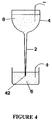
- FIG 4 there is shown a device which can be used to rapidly concentrate and purify small amounts of biological material prior to analysis.
- an upper reservoir 4 is filled with ampholytes contained in a buffer 8.
- the reservoir 6 at the lower end of the vessel 2 has a positive terminal from the power source (not shown) connected therein.
- the reservoir 4 has a negative or ground terminal from the same power source connected therein.
- target proteins within the buffer 8 are concentrated and focused inside the cone-shaped capillary 2 which is uncoated. Then, that part of the sample containing the positively charged ampholytes (the pI of which is higher than the buffer pH) and neutral species is removed from the reservoir 4. Then, the content of the capillary is emptied for collection.
- the electroosmotic flow which flows from the lower to upper reservoir prevents the neutral species from entering the capillary, but it also slows down the focusing process.
- a positive pressure can be applied to the upper reservoir 4 or a vacuum to the lower reservoir 6 to increase hydrodynamic flow in the capillary.
- the device shown in Figure 4 can also be used to fractionate ampholytic components of biological material when using several anodic containers (only one of which is shown in Figure 4). Initially, all sample components, for which pI is low enough to allow passage through the capillary, will be collected in a first reservoir 6 and will constitute a first fraction.
- the first anodic container 6 will be replaced with a second anodic container (not shown) and a tip 42 of the capillary 2 will be placed in the second container and the current in the system will be slightly lowered, thereby lowering the temperature in the tip 42.
- the current is lowered by lowering the potential. This will cause an increase in pH in the buffer in the tip. Proteins within the capillary, which have a low enough pI and are located at the very tip of the capillary, will be charged negatively and will migrate to the second anodic container.
- This process can be repeated several times by successively lowering the current still further to fractionate biological material focused and concentrated inside the cone-shaped capillary to create further fractions as desired.
- the process can be performed in a continuous and automated fashion and can be used for concentration fractionation and separation.
- a separation vessel 44 has a constant inside diameter but a conductive outer wall 46 of varying thickness.
- a temperature gradient is created in the same manner as the temperature gradient for the separation vessel 2 shown in Figure 1 except that the electrodes are connected to the conducting wall 46 as well as being connected into the buffer within the vessel.
- a temperature gradient is created within the wall 46 and the heat from the wall 46 is conducted into the buffer within the vessel 44 to create a similar temperature gradient within the buffer.
- the positive electrode (not shown) is connected to the narrow end of the wall 46 and the negative electrode (not shown) is connected to the wide end of the wall 46. While a single power source is preferred, separate power sources could be used, one for the wall 46 and one for isoelectric focusing.
- FIG 6 there is shown a continuous flow separation vessel 52 having two non-parallel walls 54, 56.
- the walls converge with one another so that the vessel has a V-shaped cross-section with an inlet 38 and an outlet 60 so that a buffer can flow into and out of said vessel continuously in a direction normal to said cross-section.
- Collectors 62 at the outlet 60 collect part of the buffer that contains focused ampholytes of interest in the location along the length of the vessel where the collectors are located. While the electrodes are not shown in Figure 6, the positive electrode would be connected into the buffer at a narrow end 64 and the negative electrode would be connected into the buffer at the wide end 66.
- the end walls themselves could be membrane protected electrodes.
- the width of the isoelectric focusing (IEF) bands can be estimated from the distance between the two forms of hemoglobin present in the sample (0.2 pH units) and corresponds to about 0.04 pH units.
- the estimated change in pH between the two ends of the cone-shaped capillary is about one pH unit. This corresponds to a temperature difference of about 40°C between the two ends.
- buffers which have a larger temperature co-efficient of pH can be used.
- the temperature differential can be increased by narrowing the smaller end of the capillary or by increasing the electrophoretic current by increasing the electrical potential.
- This approach might require cooling down the buffer reservoirs to prevent denaturing of proteins at high temperatures generated inside the capillary.
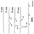
- Steady state temperature conditions were not reached in Figure 3 even after 30 minutes since the bands were still changing position along the capillary between 32 minutes and 37 minutes.
- the drift that occurred between 32 minutes and 37 minutes was smaller than the drift that occurred between 27 minutes and 32 minutes and therefore the system was very close to reaching steady state temperature conditions.
- the presence of the flow also produces more rapid thermal equilibration as indicated by the very stable analyte band position in the capillary.
- a peak 72 lies at approximately the 19.5 mm location along the capillary after 3 minutes, after 4 minutes and after 7 minutes.
- the resolution in Figure 8 decreased about 50% compared to the resolution in Figure 7 and is most likely caused by the flow in the system.
- the isoelectric focusing technique of the present invention can be used not only for analytical and preparative separations but also for preconcentration and purification of biological samples prior to analysis.
- the isoelectric focusing system can be used for trapping and concentrating target ampholytes (for example, proteins, peptides, amino acids or any other substances having an isoelectric point) in the capillary followed by mobilization of analytes towards the detection or collection point by increasing the electrical potential.
- target ampholytes for example, proteins, peptides, amino acids or any other substances having an isoelectric point
- Cone-shaped capillaries of 4 cm in length were used as the separation concentration channel and were drawn from 5 mm inside diameter glass tubes.
- the i. d. of one end of the capillary was 0.2 mm and another end was 1 mm.
- the capillary was mounted on a cartridge and its two ends were connected to buffer reservoirs as shown in Figure 1.
- the inner wall of the capillary was coated with non-cross-linked poly (acrylamide) to eliminate electrcosmosis by the reported way.
- Cross-linked poly (acrylamide) could also be used.
- the separation was driven by a high-voltage DC power supply (Spellman, Plainview, NY), and the separation voltage was about 1 kV.
- the anode was inserted into the buffer reservoir at the narrower end of the capillary, and the another end of the capillary was connected to ground.
- the protein sample used in the experiment was human hemoglobin (Sigma, St. Louis, MO) which contained two major isoforms; methemoglobin (75%) and oxyhemoglobin (25%). All chemicals were reagent grade, and solutions were prepared using deionized water.
- the buffer as 0.05 M TRIS buffer at pH 7.3. This buffer has a large temperature co-efficient of pH (dpH/dT is -0.028K -1 at 25°C) (10). Protein solutions were prepared in the TRIS buffer. The solutions were filtered using 0.2- ⁇ m pore size cellulose acetate filters (Sartorius, Gottingen, Germany).
- a UV-vis absorption imaging detector was employed for the monitoring of the protein zones focused inside the capillary.
- the light source of the detector was a halogen lamp.
- the sensor was a 1024 pixel CCD (Type S3903-1024Q, Hammamatsu, Hammamatsu City, Japan).
- a bandpass coloured filter 400 nm - 600 nm was used to cut near IR and ultraviolet radiations of the lamp.
- the light beam was first collimated as shown in Figure 2, and then focused into the capillary by three cylindrical lenses. The image of the capillary was projected into the CCD sensor as shown in Figure 2.
- the coated capillary was filled with the buffer, and plugs of 1% agarose gel (prepared in the buffer) were placed in both reservoirs to avoid hydrodynamic flow in the system, and then the voltage was applied. After 10 minutes, a few drops of 0.1 mg/mL sample solution was added to the top of the reservoir at the cathodic end of the capillary.
- the reservoirs and the uncoated capillary were filled with the protein solution and the voltage was applied. In all experiments, the current passing through the capillary was kept at about 0.8 mA by adjusting the applied voltage to about 1 kV. All experiments were done in triplicate to ensure reproducibility.
- the reservoir 6 at the narrow end of the capillary can be kept at a predetermined temperature to produce a low enough pH of the buffer to positively charge target proteins present in the reservoir (i.e. the sample that was added to the anodic reservoir). These proteins will then migrate through the capillary toward the cathode and will be trapped in the capillary at their isoelectric points or will be collected at the reservoir 4 connected to the wide end of the capillary.
- the system can be used to purify the biological material by fractionating it with respect to the isoelectric point.
- the cathodic end reservoir 4 will contain proteins which have a lower pI than the buffer in the reservoir 4 which is kept at room temperature.
- the anodic reservoir will contain proteins at a pI that is higher than the pH of the buffer in that reservoir while the capillary will contain proteins which have intermediate pI.
- the anodic reservoir 6 will be heated up in the process and that will speed up the concentration and focusing process when the sample is introduced to both the cathodic and anodic reservoirs.
Claims (18)
- Vorrichtung zur Isoelektrofokussierung von in einem Puffer (8) enthaltenen Ampholyten, wobei die Vorrichtung einen länglichen Trennungsbehälter (2) mit zwei Enden aufweist, der den Puffer enthält, die Vorrichtung außerdem eine Stromquelle aufweist, die einen konstanten Strom erzeugt, die Stromquelle einen Anschluß (10), der mit einem Ende des Behälters verbunden ist, und einen weiteren Anschluß (12) aufweist, der mit einem anderen Ende des Behälters verbunden ist, wobei die Vorrichtung dadurch gekennzeichnet ist, daß der Behälter physikalische Eigenschaften besitzt, so daß die Stromquelle angeschlossen werden kann, um entlang dem Puffer in dem Behälter ein Temperaturgefälle zu erzeugen und gekennzeichnet durch ein Erfassungssystem zur Überwachung der Fokussierungsfortschritte.
- Vorrichtung nach Anspruch 1, wobei der Trennungsbehälter (2) eine kegelförmige Kapillarröhre ist.
- Vorrichtung nach Anspruch 2, wobei die Stromquelle eine Gleichstromquelle ist, eine positive Elektrode der Stromquelle in den Puffer an einem engen Ende (16) der Kapillarröhre und eine negative Elektrode der Gleichstromquelle in den Puffer an einem breiten Ende (18) der Kapillarröhre eingefügt sind.
- Vorrichtung nach Anspruch 3, wobei es an jedem Ende der Kapillarröhre ein Reservoir gibt, das Reservoir den Puffer enthält und die Elektroden in das Reservoir eingefügt sind.
- Vorrichtung nach Anspruch 1, wobei der Trennungsbehälter (44) einen länglichen Kanal mit konstanten Innenabmessungen beinhaltet und an seiner Außenwand eine leitfähige Oberfläche (46) besitzt, deren Dicke sich von einem Ende des Kanals zu dem anderen verändert, eine positive Elektrode mit der Außenwand an einem engen Ende (48) und eine negative Elektrode an einem breiten Ende (50) mit der Wand verbunden sind.
- Vorrichtung nach Anspruch 5, wobei die Stromquelle eine Gleichstromquelle ist und das enge Ende eine höhere Temperatur als das breite Ende besitzt.
- Vorrichtung nach Anspruch 5, wobei die leitfähige Oberfläche (46) die Außenwand des länglichen Kanals völlig umgibt.
- Vorrichtung nach einem der Ansprüche 1, 2 oder 5, wobei das Erfassungssystem ein Absorptionsbild-Erfassungssystem ist, welches ununterbrochen den Fortschritt der Fokussierung überwacht, und der Trennungsbehälter durchsichtig ist.
- Vorrichtung nach einem der Ansprüche 1, 2 oder 5, wobei eine Innenwand des Behälters mit einer Substanz beschichtet ist, um einen elektroosmotischen Fluß zu verhindern.
- Vorrichtung nach Anspruch 7, wobei die Vorrichtung zum Fokussieren von Eiweiß verwendet wird und die Innenwand mit Poly(acrylamid) beschichtet ist.
- Vorrichtung nach einem der Ansprüche 1, 2 oder 5, wobei der Behälter einen Einlaßkanal (58) und einen Auslaßkanal (60) besitzt, so daß der Puffer durch den Behälter (52) ununterbrochen in einer Richtung senkrecht zu einer Längsachse des Behälters fließen kann und an dem Auslaßkanal angeordnete Sammelvorrichtungen (62) besitzt, um einen fokussierten Teil des Puffers aufzufangen.
- Vorrichtung nach Anspruch 1, wobei der Behälter (52) zwei Seitenwände (54, 56) besitzt, welche sich einander nähern, so daß der Behälter einen V-förmigen Querschnitt mit einem Einlaßkanal (58) und einem Auslaßkanal (60) aufweist und der Puffer dadurch ununterbrochen in einer Richtung senkrecht zu dem Querschnitt in den Behälter und aus diesem heraus fließen kann.
- Vorrichtung nach Anspruch 12, wobei es an dem Auslaßkanal (60) zumindest eine Auffangeinrichtung (62) gibt, um einen Teil des fokussierten Puffers aufzufangen.
- Vorrichtung nach einem der Ansprüche 1, 2 oder 5, wobei die Spannung in dem Behälter im wesentlichen 1 kV beträgt.
- Vorrichtung nach einem der Ansprüche 1, 2 oder 5, wobei die Spannung in dem Behälter von 100 Volt pro cm Länge bis 1 kV pro cm Länge reicht.
- Verfahren zur Isoelektrofokussierung von Ampholyten, die in einem Puffer (8) enthalten sind, unter Verwendung eines länglichen Trennungsbehälters (2) mit zwei Enden, wobei der Behälter physikalische Eigenschaften besitzt, so daß in dem Behälterinhalt durch Verwendung eines konstanten Stroms von einer Stromquelle ein Temperaturgefälle erzeugt werden kann, und ein Bilderfassungssystem zur Überwachung der Fortschritte der Fokussierung aufweist, der Behälter mit einem Ampholyte enthaltenden Puffer gefüllt ist, wobei das Verfahren dadurch gekennzeichnet ist, daß die Stromquelle angeschlossen ist, um entlang dem Puffer in dem Behälter ein Temperaturgefälle zu erzeugen und die Ampholyte zu fokussieren, und der Fortschritt der Fokussierung durch Verwendung des Erfassungssystems überwacht wird.
- Verfahren zur Fraktionierung der ampholytischen Komponenten aus biologischem Material, die in einem Puffer (8) enthalten sind, unter Verwendung eines länglichen Trennungsbehälters (2) mit zwei Enden, wobei der Behälter physikalische Eigenschaften besitzt, so daß in dem Behälterinhalt durch Verwendung eines Konstantstroms, der von einer Stromquelle erzeugt wurde, von der ein Anschluß (10) an einem Ende des Behälters und deren anderer Anschluß (12) an dem anderen Ende angeschlossen ist, ein Temperaturgefälle erzeugt wird, wobei sich an jedem Ende des Behälters ein Reservoir für die Anschlüsse befindet, eines der Reservoirs (4, 6) ein kathodisches Reservoir und das andere Reservoir (6) ein anodisches Reservoir ist, es mehrere voneinander getrennte anodische Reservoirs gibt und das Verfahren die Schritte aufweist: Aktivieren des Stroms, bevor alle Komponenten des Puffers mit einem pI, das genügend niedrig ist, durch den Behälter in ein erstes anodisches Reservoir fließen, Ersetzen des ersten anodischen Reservoirs durch ein zweites anodisches Reservoir und Aktivieren des Systems durch einen etwas geringeren Strom als dem, der bei dem ersten Reservoir verwendet wurde, wodurch bewirkt wird, daß ein Teil der Ampholyte, der sich durch die Fokussierung an einem Ende des Behälters befindet und ein genügend niederes pI besitzt, negativ aufgeladen wird und in den zweiten anodischen Behälter abwandert, Ersetzen des zweiten anodischen Behälters durch einen dritten anodischen Behälter und Wiederholen des Prozesses mit einem noch geringeren Strom, um einen weiteren Teil der Ampholyte, der sich durch die Fokussierung an einem Ende des Behälters befindet und ein genügend niederes pI besitzt, in den dritten anodischen Behälter abwandern zu lassen, fortgesetzte Wiederholung des Prozesses mit aufeinanderfolgenden anodischen Behältern und aufeinanderfolgenden Reduzierungen des Stroms, bis eine ausreichende Fraktionierung der ampholytischen Komponenten erzielt wurde.
- Verfahren nach Anspruch 17, wobei der Behälter eine kegelförmige Kapillarröhre ist, die an einem Ende eine Spitze besitzt und die Spitze der Kapillarröhre in aufeinanderfolgende anodische Behälter getaucht wird.
Applications Claiming Priority (3)
| Application Number | Priority Date | Filing Date | Title |
|---|---|---|---|
| US2663593A | 1993-03-05 | 1993-03-05 | |
| US26635 | 1993-03-05 | ||
| PCT/CA1994/000120 WO1994020843A1 (en) | 1993-03-05 | 1994-03-02 | Method and device for isoelectric focusing without carrier ampholytes |
Publications (2)
| Publication Number | Publication Date |
|---|---|
| EP0687358A1 EP0687358A1 (de) | 1995-12-20 |
| EP0687358B1 true EP0687358B1 (de) | 1997-05-07 |
Family
ID=21832965
Family Applications (1)
| Application Number | Title | Priority Date | Filing Date |
|---|---|---|---|
| EP94908235A Expired - Lifetime EP0687358B1 (de) | 1993-03-05 | 1994-03-02 | Verfahren und vorrichtung zur isoelektrofokussierung ohne tragerampholyten |
Country Status (6)
| Country | Link |
|---|---|
| US (1) | US5759370A (de) |
| EP (1) | EP0687358B1 (de) |
| JP (1) | JP3410099B2 (de) |
| CA (1) | CA2157373C (de) |
| DE (1) | DE69403071D1 (de) |
| WO (1) | WO1994020843A1 (de) |
Cited By (1)
| Publication number | Priority date | Publication date | Assignee | Title |
|---|---|---|---|---|
| DE102018115200A1 (de) * | 2018-06-25 | 2020-01-02 | Lisa Laser Products Gmbh | Verfahren und Vorrichtung zum optischen Messen einer in einem Probenröhrchen mit konischem Boden angeordneten Probe |
Families Citing this family (13)
| Publication number | Priority date | Publication date | Assignee | Title |
|---|---|---|---|---|
| US5658446A (en) * | 1996-01-22 | 1997-08-19 | Hewlett-Packard Company | Preparative capillary electrophoresis with wide-bore capillary |
| JP3077609B2 (ja) * | 1996-10-31 | 2000-08-14 | 株式会社島津製作所 | マイクロチップ電気泳動方法及び装置 |
| EP1009995A4 (de) * | 1997-09-02 | 2007-05-02 | Caliper Life Sciences Inc | Mikrofluidisches system mit elektrofluidischer und elektrothermischer regelung |
| US5965410A (en) * | 1997-09-02 | 1999-10-12 | Caliper Technologies Corp. | Electrical current for controlling fluid parameters in microchannels |
| US6174675B1 (en) * | 1997-11-25 | 2001-01-16 | Caliper Technologies Corp. | Electrical current for controlling fluid parameters in microchannels |
| US6268219B1 (en) | 1999-07-09 | 2001-07-31 | Orchid Biosciences, Inc. | Method and apparatus for distributing fluid in a microfluidic device |
| WO2002044707A1 (en) * | 2000-11-29 | 2002-06-06 | Proteologics Inc. | Method and apparatus for decoupling temperature and electric field in electrophoresis separation |
| US7029561B2 (en) * | 2001-07-25 | 2006-04-18 | The United States Of America As Represented By The Secretary Of Commerce | Fluidic temperature gradient focusing |
| US20110094886A1 (en) * | 2008-05-05 | 2011-04-28 | Celal Korkut Vata | Automated, High Band Resolution Electrophoretic System for Digital Visualization and Method of Use |
| HUE034403T2 (en) * | 2009-11-04 | 2018-02-28 | Ffgf Ltd | Preparation of hydrocarbons |
| ES2746876T3 (es) * | 2014-12-22 | 2020-03-09 | Eurotrol B V | Contenedor que comprende fracciones de hemoglobina |
| US11275054B2 (en) | 2018-02-13 | 2022-03-15 | Jp Scientific Limited | Ion mobility spectrometer and method of analyzing ions |
| US11874251B2 (en) | 2018-02-13 | 2024-01-16 | Jp Scientific Limited | Ion mobility spectrometer and method of analyzing ions |
Family Cites Families (9)
| Publication number | Priority date | Publication date | Assignee | Title |
|---|---|---|---|---|
| US3664939A (en) * | 1970-04-22 | 1972-05-23 | Univ California | ISOELECTRIC FOCUSING AND FRACTIONATION AMPHOLYTES IN THERMALLY ENGENDERED pH GRADIENTS |
| US4401538A (en) * | 1981-06-02 | 1983-08-30 | Hausfeld David A | Isoelectric focusing techniques and devices |
| US4725343A (en) * | 1985-10-15 | 1988-02-16 | Bio-Rad Laboratories, Inc. | High performance electrophoretic mobilization of isoelectrically focused protein zones |
| DE3622591C2 (de) * | 1986-07-04 | 1998-11-19 | Qiagen Gmbh | Verfahren und Vorrichtung zur Herstellung eines regelbaren und reproduzierbaren Temperaturgradienten und seine Verwendung |
| US4844786A (en) * | 1987-02-26 | 1989-07-04 | Fuji Photo Film Co., Ltd. | Means for electrophoresis |
| US4834862A (en) * | 1988-09-12 | 1989-05-30 | Duke University | Ampholyte separation method and apparatus |
| US5324413A (en) * | 1989-03-06 | 1994-06-28 | Hewlett-Packard Company | Electrophoresis capillary with dispersion-inhibiting cross-section |
| ATE145010T1 (de) * | 1989-08-19 | 1996-11-15 | Qiagen Gmbh | Verfahren und vorrichtung zur trennung und detektion von komponenten eines stoffgemisches durch temperaturgradienten-gelelektrophorese |
| US5110434A (en) * | 1990-12-20 | 1992-05-05 | Bio-Rad Laboratories, Inc. | Use of zwitterions to mobilize isoelectrically focused ampholyte zones |
-
1994
- 1994-03-02 DE DE69403071T patent/DE69403071D1/de not_active Expired - Lifetime
- 1994-03-02 CA CA002157373A patent/CA2157373C/en not_active Expired - Fee Related
- 1994-03-02 JP JP51941894A patent/JP3410099B2/ja not_active Expired - Fee Related
- 1994-03-02 WO PCT/CA1994/000120 patent/WO1994020843A1/en active IP Right Grant
- 1994-03-02 EP EP94908235A patent/EP0687358B1/de not_active Expired - Lifetime
-
1995
- 1995-03-24 US US08/309,595 patent/US5759370A/en not_active Expired - Fee Related
Cited By (2)
| Publication number | Priority date | Publication date | Assignee | Title |
|---|---|---|---|---|
| DE102018115200A1 (de) * | 2018-06-25 | 2020-01-02 | Lisa Laser Products Gmbh | Verfahren und Vorrichtung zum optischen Messen einer in einem Probenröhrchen mit konischem Boden angeordneten Probe |
| DE102018115200B4 (de) * | 2018-06-25 | 2020-02-13 | Lisa Laser Products Gmbh | Verfahren und Vorrichtung zum optischen Messen einer in einem Probenröhrchen mit konischem Boden angeordneten Probe |
Also Published As
| Publication number | Publication date |
|---|---|
| EP0687358A1 (de) | 1995-12-20 |
| CA2157373C (en) | 2005-06-07 |
| JPH08507374A (ja) | 1996-08-06 |
| CA2157373A1 (en) | 1994-09-15 |
| US5759370A (en) | 1998-06-02 |
| WO1994020843A1 (en) | 1994-09-15 |
| DE69403071D1 (de) | 1997-06-12 |
| JP3410099B2 (ja) | 2003-05-26 |
Similar Documents
| Publication | Publication Date | Title |
|---|---|---|
| EP0687358B1 (de) | Verfahren und vorrichtung zur isoelektrofokussierung ohne tragerampholyten | |
| JP2731034B2 (ja) | 等電点電気泳動させた両電解質帯を移動させるための両性イオンの利用 | |
| US5202010A (en) | Automated capillary electrophoresis apparatus | |
| EP0477541B1 (de) | Vorrichtung zur Gewinnung von durch Kapillarelektrophorese getrennten Proben auf einer Membran | |
| EP0687905B1 (de) | Selbsttätige kapillare Elektroforesevorrichtung | |
| US5468359A (en) | Method of determining presence of an analyte by isoelectric focusing | |
| Vesterberg | [33] Isoelectric focusing of proteins | |
| US5505831A (en) | Concentration of biological samples on a microliter scale and analysis by capillary electrophoresis | |
| US5085756A (en) | Column separation system for electrophoresis with sample pretreatment | |
| US8685219B1 (en) | Apparatus for capillary electrophoresis with polyelectrolyte multilayer coating on the capillary walls | |
| US5151165A (en) | Methods and apparatuses for preparative electrophoresis | |
| US5784154A (en) | Electrophoresis separation in a capillary passage | |
| EP0630473A1 (de) | Elektrisches trennungsgerät und verfahren zur gegenstromfokalisierung eines gradientes | |
| US4588492A (en) | Rotating apparatus for isoelectric focusing | |
| Faupel et al. | Isoelectric protein purification by orthogonally coupled hydraulic and electric transports in a segmented immobilized pH gradient | |
| EP0397699B1 (de) | Selbsttätige kapillare elektrophorese-vorrichtung | |
| US4834862A (en) | Ampholyte separation method and apparatus | |
| US4824547A (en) | Electrophoretic extraction of proteins from two-dimensional electrophoresis gel spots | |
| Bergmann et al. | Potential of on-line isotachophoresis-capillary zone electrophoresis with hydrodynamic counterflow in the analysis of various basic proteins and recombinant human interleukin-3 | |
| EP2773959A1 (de) | Proteinfraktionierung auf pl-basis | |
| CA2127977C (en) | Method and apparatus for performing and universally detecting capillary isoelectric focusing without mobilization using concentration gradient imaging systems | |
| Tulp et al. | A separation chamber to sort cells and cell organelles by weak physical forces: III. Preparative electrophoresis of cells in stationary density gradients at low electric field strength | |
| WO1993014389A1 (en) | Method and apparatus for performing and universally detecting capillary isoelectric focusing without mobilization using concentration gradient imaging systems | |
| Svendsen | Preparative isotachophoresis | |
| Pláteník | in biochemistry |
Legal Events
| Date | Code | Title | Description |
|---|---|---|---|
| PUAI | Public reference made under article 153(3) epc to a published international application that has entered the european phase |
Free format text: ORIGINAL CODE: 0009012 |
|
| 17P | Request for examination filed |
Effective date: 19951002 |
|
| AK | Designated contracting states |
Kind code of ref document: A1 Designated state(s): CH DE FR GB IT LI NL SE |
|
| GRAG | Despatch of communication of intention to grant |
Free format text: ORIGINAL CODE: EPIDOS AGRA |
|
| 17Q | First examination report despatched |
Effective date: 19960618 |
|
| GRAH | Despatch of communication of intention to grant a patent |
Free format text: ORIGINAL CODE: EPIDOS IGRA |
|
| GRAH | Despatch of communication of intention to grant a patent |
Free format text: ORIGINAL CODE: EPIDOS IGRA |
|
| GRAA | (expected) grant |
Free format text: ORIGINAL CODE: 0009210 |
|
| AK | Designated contracting states |
Kind code of ref document: B1 Designated state(s): CH DE FR GB IT LI NL SE |
|
| PG25 | Lapsed in a contracting state [announced via postgrant information from national office to epo] |
Ref country code: NL Free format text: LAPSE BECAUSE OF FAILURE TO SUBMIT A TRANSLATION OF THE DESCRIPTION OR TO PAY THE FEE WITHIN THE PRESCRIBED TIME-LIMIT Effective date: 19970507 Ref country code: LI Effective date: 19970507 Ref country code: IT Free format text: LAPSE BECAUSE OF FAILURE TO SUBMIT A TRANSLATION OF THE DESCRIPTION OR TO PAY THE FEE WITHIN THE PRE;WARNING: LAPSES OF ITALIAN PATENTS WITH EFFECTIVE DATE BEFORE 2007 MAY HAVE OCCURRED AT ANY TIME BEFORE 2007. THE CORRECT EFFECTIVE DATE MAY BE DIFFERENT FROM THE ONE RECORDED.SCRIBED TIME-LIMIT Effective date: 19970507 Ref country code: FR Effective date: 19970507 Ref country code: CH Effective date: 19970507 |
|
| REG | Reference to a national code |
Ref country code: CH Ref legal event code: EP |
|
| REF | Corresponds to: |
Ref document number: 69403071 Country of ref document: DE Date of ref document: 19970612 |
|
| PG25 | Lapsed in a contracting state [announced via postgrant information from national office to epo] |
Ref country code: SE Effective date: 19970807 |
|
| PG25 | Lapsed in a contracting state [announced via postgrant information from national office to epo] |
Ref country code: DE Effective date: 19970808 |
|
| NLV1 | Nl: lapsed or annulled due to failure to fulfill the requirements of art. 29p and 29m of the patents act | ||
| EN | Fr: translation not filed | ||
| REG | Reference to a national code |
Ref country code: CH Ref legal event code: PL |
|
| PLBE | No opposition filed within time limit |
Free format text: ORIGINAL CODE: 0009261 |
|
| STAA | Information on the status of an ep patent application or granted ep patent |
Free format text: STATUS: NO OPPOSITION FILED WITHIN TIME LIMIT |
|
| 26N | No opposition filed | ||
| REG | Reference to a national code |
Ref country code: GB Ref legal event code: IF02 |
|
| PGFP | Annual fee paid to national office [announced via postgrant information from national office to epo] |
Ref country code: GB Payment date: 20060303 Year of fee payment: 13 |
|
| GBPC | Gb: european patent ceased through non-payment of renewal fee |
Effective date: 20070302 |
|
| PG25 | Lapsed in a contracting state [announced via postgrant information from national office to epo] |
Ref country code: GB Free format text: LAPSE BECAUSE OF NON-PAYMENT OF DUE FEES Effective date: 20070302 |