EP0687199B1 - Method of producing spherical particles - Google Patents
Method of producing spherical particles Download PDFInfo
- Publication number
- EP0687199B1 EP0687199B1 EP94909898A EP94909898A EP0687199B1 EP 0687199 B1 EP0687199 B1 EP 0687199B1 EP 94909898 A EP94909898 A EP 94909898A EP 94909898 A EP94909898 A EP 94909898A EP 0687199 B1 EP0687199 B1 EP 0687199B1
- Authority
- EP
- European Patent Office
- Prior art keywords
- sol
- oxide
- particles
- reaction
- reaction zone
- Prior art date
- Legal status (The legal status is an assumption and is not a legal conclusion. Google has not performed a legal analysis and makes no representation as to the accuracy of the status listed.)
- Expired - Lifetime
Links
Images


Classifications
-
- B—PERFORMING OPERATIONS; TRANSPORTING
- B01—PHYSICAL OR CHEMICAL PROCESSES OR APPARATUS IN GENERAL
- B01J—CHEMICAL OR PHYSICAL PROCESSES, e.g. CATALYSIS OR COLLOID CHEMISTRY; THEIR RELEVANT APPARATUS
- B01J21/00—Catalysts comprising the elements, oxides, or hydroxides of magnesium, boron, aluminium, carbon, silicon, titanium, zirconium, or hafnium
- B01J21/18—Carbon
-
- B—PERFORMING OPERATIONS; TRANSPORTING
- B01—PHYSICAL OR CHEMICAL PROCESSES OR APPARATUS IN GENERAL
- B01J—CHEMICAL OR PHYSICAL PROCESSES, e.g. CATALYSIS OR COLLOID CHEMISTRY; THEIR RELEVANT APPARATUS
- B01J2/00—Processes or devices for granulating materials, e.g. fertilisers in general; Rendering particulate materials free flowing in general, e.g. making them hydrophobic
- B01J2/02—Processes or devices for granulating materials, e.g. fertilisers in general; Rendering particulate materials free flowing in general, e.g. making them hydrophobic by dividing the liquid material into drops, e.g. by spraying, and solidifying the drops
- B01J2/04—Processes or devices for granulating materials, e.g. fertilisers in general; Rendering particulate materials free flowing in general, e.g. making them hydrophobic by dividing the liquid material into drops, e.g. by spraying, and solidifying the drops in a gaseous medium
-
- B—PERFORMING OPERATIONS; TRANSPORTING
- B01—PHYSICAL OR CHEMICAL PROCESSES OR APPARATUS IN GENERAL
- B01J—CHEMICAL OR PHYSICAL PROCESSES, e.g. CATALYSIS OR COLLOID CHEMISTRY; THEIR RELEVANT APPARATUS
- B01J2/00—Processes or devices for granulating materials, e.g. fertilisers in general; Rendering particulate materials free flowing in general, e.g. making them hydrophobic
- B01J2/02—Processes or devices for granulating materials, e.g. fertilisers in general; Rendering particulate materials free flowing in general, e.g. making them hydrophobic by dividing the liquid material into drops, e.g. by spraying, and solidifying the drops
- B01J2/06—Processes or devices for granulating materials, e.g. fertilisers in general; Rendering particulate materials free flowing in general, e.g. making them hydrophobic by dividing the liquid material into drops, e.g. by spraying, and solidifying the drops in a liquid medium
- B01J2/08—Gelation of a colloidal solution
-
- B—PERFORMING OPERATIONS; TRANSPORTING
- B01—PHYSICAL OR CHEMICAL PROCESSES OR APPARATUS IN GENERAL
- B01J—CHEMICAL OR PHYSICAL PROCESSES, e.g. CATALYSIS OR COLLOID CHEMISTRY; THEIR RELEVANT APPARATUS
- B01J23/00—Catalysts comprising metals or metal oxides or hydroxides, not provided for in group B01J21/00
- B01J23/38—Catalysts comprising metals or metal oxides or hydroxides, not provided for in group B01J21/00 of noble metals
- B01J23/40—Catalysts comprising metals or metal oxides or hydroxides, not provided for in group B01J21/00 of noble metals of the platinum group metals
-
- B—PERFORMING OPERATIONS; TRANSPORTING
- B01—PHYSICAL OR CHEMICAL PROCESSES OR APPARATUS IN GENERAL
- B01J—CHEMICAL OR PHYSICAL PROCESSES, e.g. CATALYSIS OR COLLOID CHEMISTRY; THEIR RELEVANT APPARATUS
- B01J37/00—Processes, in general, for preparing catalysts; Processes, in general, for activation of catalysts
- B01J37/0009—Use of binding agents; Moulding; Pressing; Powdering; Granulating; Addition of materials ameliorating the mechanical properties of the product catalyst
- B01J37/0027—Powdering
- B01J37/0045—Drying a slurry, e.g. spray drying
-
- B—PERFORMING OPERATIONS; TRANSPORTING
- B01—PHYSICAL OR CHEMICAL PROCESSES OR APPARATUS IN GENERAL
- B01J—CHEMICAL OR PHYSICAL PROCESSES, e.g. CATALYSIS OR COLLOID CHEMISTRY; THEIR RELEVANT APPARATUS
- B01J37/00—Processes, in general, for preparing catalysts; Processes, in general, for activation of catalysts
- B01J37/0072—Preparation of particles, e.g. dispersion of droplets in an oil bath
-
- C—CHEMISTRY; METALLURGY
- C01—INORGANIC CHEMISTRY
- C01B—NON-METALLIC ELEMENTS; COMPOUNDS THEREOF; METALLOIDS OR COMPOUNDS THEREOF NOT COVERED BY SUBCLASS C01C
- C01B13/00—Oxygen; Ozone; Oxides or hydroxides in general
- C01B13/14—Methods for preparing oxides or hydroxides in general
- C01B13/34—Methods for preparing oxides or hydroxides in general by oxidation or hydrolysis of sprayed or atomised solutions
-
- C—CHEMISTRY; METALLURGY
- C01—INORGANIC CHEMISTRY
- C01B—NON-METALLIC ELEMENTS; COMPOUNDS THEREOF; METALLOIDS OR COMPOUNDS THEREOF NOT COVERED BY SUBCLASS C01C
- C01B33/00—Silicon; Compounds thereof
- C01B33/113—Silicon oxides; Hydrates thereof
- C01B33/12—Silica; Hydrates thereof, e.g. lepidoic silicic acid
- C01B33/16—Preparation of silica xerogels
-
- C—CHEMISTRY; METALLURGY
- C01—INORGANIC CHEMISTRY
- C01F—COMPOUNDS OF THE METALS BERYLLIUM, MAGNESIUM, ALUMINIUM, CALCIUM, STRONTIUM, BARIUM, RADIUM, THORIUM, OR OF THE RARE-EARTH METALS
- C01F7/00—Compounds of aluminium
- C01F7/02—Aluminium oxide; Aluminium hydroxide; Aluminates
- C01F7/44—Dehydration of aluminium oxide or hydroxide, i.e. all conversions of one form into another involving a loss of water
- C01F7/441—Dehydration of aluminium oxide or hydroxide, i.e. all conversions of one form into another involving a loss of water by calcination
-
- C—CHEMISTRY; METALLURGY
- C02—TREATMENT OF WATER, WASTE WATER, SEWAGE, OR SLUDGE
- C02F—TREATMENT OF WATER, WASTE WATER, SEWAGE, OR SLUDGE
- C02F1/00—Treatment of water, waste water, or sewage
- C02F1/70—Treatment of water, waste water, or sewage by reduction
-
- C—CHEMISTRY; METALLURGY
- C01—INORGANIC CHEMISTRY
- C01P—INDEXING SCHEME RELATING TO STRUCTURAL AND PHYSICAL ASPECTS OF SOLID INORGANIC COMPOUNDS
- C01P2004/00—Particle morphology
- C01P2004/01—Particle morphology depicted by an image
-
- C—CHEMISTRY; METALLURGY
- C01—INORGANIC CHEMISTRY
- C01P—INDEXING SCHEME RELATING TO STRUCTURAL AND PHYSICAL ASPECTS OF SOLID INORGANIC COMPOUNDS
- C01P2004/00—Particle morphology
- C01P2004/01—Particle morphology depicted by an image
- C01P2004/03—Particle morphology depicted by an image obtained by SEM
-
- C—CHEMISTRY; METALLURGY
- C01—INORGANIC CHEMISTRY
- C01P—INDEXING SCHEME RELATING TO STRUCTURAL AND PHYSICAL ASPECTS OF SOLID INORGANIC COMPOUNDS
- C01P2004/00—Particle morphology
- C01P2004/30—Particle morphology extending in three dimensions
- C01P2004/32—Spheres
-
- C—CHEMISTRY; METALLURGY
- C01—INORGANIC CHEMISTRY
- C01P—INDEXING SCHEME RELATING TO STRUCTURAL AND PHYSICAL ASPECTS OF SOLID INORGANIC COMPOUNDS
- C01P2004/00—Particle morphology
- C01P2004/51—Particles with a specific particle size distribution
- C01P2004/52—Particles with a specific particle size distribution highly monodisperse size distribution
-
- C—CHEMISTRY; METALLURGY
- C01—INORGANIC CHEMISTRY
- C01P—INDEXING SCHEME RELATING TO STRUCTURAL AND PHYSICAL ASPECTS OF SOLID INORGANIC COMPOUNDS
- C01P2004/00—Particle morphology
- C01P2004/60—Particles characterised by their size
- C01P2004/61—Micrometer sized, i.e. from 1-100 micrometer
-
- C—CHEMISTRY; METALLURGY
- C01—INORGANIC CHEMISTRY
- C01P—INDEXING SCHEME RELATING TO STRUCTURAL AND PHYSICAL ASPECTS OF SOLID INORGANIC COMPOUNDS
- C01P2006/00—Physical properties of inorganic compounds
- C01P2006/12—Surface area
-
- C—CHEMISTRY; METALLURGY
- C01—INORGANIC CHEMISTRY
- C01P—INDEXING SCHEME RELATING TO STRUCTURAL AND PHYSICAL ASPECTS OF SOLID INORGANIC COMPOUNDS
- C01P2006/00—Physical properties of inorganic compounds
- C01P2006/14—Pore volume
-
- C—CHEMISTRY; METALLURGY
- C01—INORGANIC CHEMISTRY
- C01P—INDEXING SCHEME RELATING TO STRUCTURAL AND PHYSICAL ASPECTS OF SOLID INORGANIC COMPOUNDS
- C01P2006/00—Physical properties of inorganic compounds
- C01P2006/16—Pore diameter
-
- C—CHEMISTRY; METALLURGY
- C02—TREATMENT OF WATER, WASTE WATER, SEWAGE, OR SLUDGE
- C02F—TREATMENT OF WATER, WASTE WATER, SEWAGE, OR SLUDGE
- C02F2101/00—Nature of the contaminant
- C02F2101/10—Inorganic compounds
- C02F2101/16—Nitrogen compounds, e.g. ammonia
-
- Y—GENERAL TAGGING OF NEW TECHNOLOGICAL DEVELOPMENTS; GENERAL TAGGING OF CROSS-SECTIONAL TECHNOLOGIES SPANNING OVER SEVERAL SECTIONS OF THE IPC; TECHNICAL SUBJECTS COVERED BY FORMER USPC CROSS-REFERENCE ART COLLECTIONS [XRACs] AND DIGESTS
- Y10—TECHNICAL SUBJECTS COVERED BY FORMER USPC
- Y10S—TECHNICAL SUBJECTS COVERED BY FORMER USPC CROSS-REFERENCE ART COLLECTIONS [XRACs] AND DIGESTS
- Y10S210/00—Liquid purification or separation
- Y10S210/902—Materials removed
- Y10S210/908—Organic
- Y10S210/909—Aromatic compound, e.g. pcb, phenol
Landscapes
- Chemical & Material Sciences (AREA)
- Organic Chemistry (AREA)
- Chemical Kinetics & Catalysis (AREA)
- Engineering & Computer Science (AREA)
- Materials Engineering (AREA)
- Dispersion Chemistry (AREA)
- Inorganic Chemistry (AREA)
- Life Sciences & Earth Sciences (AREA)
- Water Supply & Treatment (AREA)
- Environmental & Geological Engineering (AREA)
- Hydrology & Water Resources (AREA)
- Geology (AREA)
- Oil, Petroleum & Natural Gas (AREA)
- Catalysts (AREA)
- Treatment Of Water By Oxidation Or Reduction (AREA)
- Physical Or Chemical Processes And Apparatus (AREA)
- Devices And Processes Conducted In The Presence Of Fluids And Solid Particles (AREA)
- Manufacturing Of Micro-Capsules (AREA)
- Water Treatment By Sorption (AREA)
- Silicon Compounds (AREA)
Abstract
Description
Die vorliegende Erfindung betrifft ein Verfahren zur Herstellung kugelförmiger Teilchen auf der Basis anorganischer Oxide und die Verwendung der nach diesem Verfahren erhältlichen Teilchen.The present invention relates to a method for producing spherical particles based on inorganic oxides and the use of the particles obtainable by this method.
Kugelförmige Teilchen auf der Basis anorganischer Oxide, z. B. auf der Basis von Siliciumdioxid, Aluminiumoxid, Alumosilikat, Magnesiumoxid, Titandioxid oder Zirkoniumdioxid, werden in großem Maßstab als Katalysatoren, Katalysatorträger, Adsorbentien, Trockenmittel oder Ionenaustauscher verwendet. Für die meisten der genannten Anwendungszwecke werden Teilchen mit einer gleichmäßigen kugelförmigen Gestalt und einem engen Kornspektrum benötigt, um somit eine möglichst gleichmäßige Packung und hohe Packungsdichte z. B. im Festbettreaktor zu ermöglichen. Werden die Teilchen im Bewegtbettreaktor eingesetzt, so wird von den Teilchen noch eine erhöhte Abriebfestigkeit erwartet. Sollen die Teilchen als Katalysatoren oder Katalysatorträger verwendet werden, so müssen sie neben einem engen Kornspektrum darüber hinaus noch eine bestimmte spezifische Oberfläche und spezifisches Porenvolumen aufweisen.Spherical particles based on inorganic oxides, e.g. B. on the basis of silicon dioxide, aluminum oxide, aluminosilicate, magnesium oxide, titanium dioxide or zirconium dioxide, are used on a large scale as catalysts, catalyst supports, adsorbents, drying agents or ion exchangers. For most of the applications mentioned, particles with a uniform spherical shape and a narrow grain spectrum are required in order to ensure that the packing is as uniform as possible and high packing density, e.g. B. in the fixed bed reactor. If the particles are used in a moving bed reactor, the particles are expected to have an increased abrasion resistance. If the particles are to be used as catalysts or catalyst supports, they must also have a specific surface area and specific pore volume in addition to a narrow grain spectrum.
Üblicherweise werden kugelförmige Teilchen auf der Basis anorganischer Oxide, beispielsweise auf der Basis von Siliciumdioxid, Aluminiumoxid, Alumosilikaten und/oder anderen Oxiden nach dem allgemein bekannten Sol-Gel-Verfahren erhalten. Die Herstellung kugelförmiger Siliciumdioxid-Teilchen erfolgt gemäß diesem Verfahren, wie es z. B. in der DE-AS 1 667 669 beschrieben ist, indem man eine wäßrige Lösung eines Alkalimetallsilikates mit einer wäßrigen Lösung einer Säure miteinander vermischt. Man erhält dabei ein Sol, welches intropfenförmige Teilchen überführt wird, die anschließend in einem sogenannten Formöl zur Gelierung gebracht werden. Als Formöl wird dabei zumeist eine mit Wasser nicht mischbare Flüssigkeit, z.B. Mineralöl, Rohpetroleum oder Kerosin, verwendet. In einem weiteren Verfahrensschritt wird dann anschließend ein sogenannter Basenaustausch durchgeführt, bei dem der Alkalimetallgehalt der erhaltenen Teilchen in einem wäßrigen Medium auf weniger als 1 Gew.-%, bezogen auf die Trockensubstanz vermindert wird. Anschließend werden die Teilchen dann noch gewaschen, getrocknet und kalziniert. Nach diesem Verfahren hängt die Ausformung der gebildeten Teilchen von der Geschwindigkeit ab, mit welcher die Soltropfen durch das Formöl hindurchfallen, wobei die Sinkgeschwindigkeit der Soltropfen vom spezifischen Gewicht und von der Viskosität der als Formöl verwendeten Flüssigkeit abhängt. Nach einer anderen an sich bekannten Methode kann die Ausformung der Teilchen auch dadurch erfolgen, daß man die nach dem Zusammenfügen der Alkalimetallsilikatlösung zur wäßrigen Säurelösung erhaltenen Soltropfen unter Einwirkung der Schwerkraft durch eine Luftsäule fallen läßt, wobei die Tropfen während des Fallens gelieren. Nach dieser Methode müssen Gelierzeit und Fallhöhe genau aufeinander abgestimmt sein. Bei noch nicht genügend verfestigten Tropfen besteht die Gefahr, daß sie beim Aufprall auf die Reaktionsflüssigkeit deformiert werden.Spherical particles based on inorganic oxides, for example based on silicon dioxide, aluminum oxide, aluminosilicates and / or other oxides, are usually obtained by the generally known sol-gel process. The production of spherical silicon dioxide particles is carried out according to this method, as described, for. B. is described in DE-AS 1 667 669 by mixing an aqueous solution of an alkali metal silicate with an aqueous solution of an acid. This gives a sol which is transferred into droplet-shaped particles which are then gelled in a so-called molding oil. The molding oil used is usually a water-immiscible liquid, e.g. mineral oil, Crude petroleum or kerosene. In a further process step, a so-called base exchange is then carried out, in which the alkali metal content of the particles obtained is reduced to less than 1% by weight, based on the dry substance, in an aqueous medium. The particles are then washed, dried and calcined. According to this method, the formation of the particles formed depends on the speed at which the sol drops drop through the molding oil, the sinking speed of the sol drops depending on the specific weight and the viscosity of the liquid used as the molding oil. According to another method known per se, the particles can also be shaped by dropping the sol drops obtained after the alkali metal silicate solution has been combined to form the aqueous acid solution under the action of gravity through an air column, the drops gelling as they fall. According to this method, the gel time and the drop height must be precisely coordinated. If the drops are not sufficiently solidified, there is a risk that they will be deformed on impact with the reaction liquid.
Nach der WO 92/07653 ist ein Sol-Gel-Verfahren bekannt, nach dem kugelförmige Teilchen auf der Basis von Aluminiumoxid hergestellt werden. Hierbei werden kugelförmige Tropfen aus einem Aluminiumoxid-Hydrosol durch eine in Vibration versetzte Düsenplatte erzeugt, welche man durch seitliches Anblasen mit Ammoniakgas vorverfestigt und dann in einer wäßrigen Ammoniaklösung auffängt. Bei der Herstellung von Teilchen größeren Durchmessers muß man die Teilchen üblicherweise eine Schaumschicht passieren lassen, damit der Aufschlag der Teilchen auf die Ammoniaklösung gebremst wird, um somit eine Deformation bzw. ein Auseinanderbrechen der Tropfen zu verhindern. Das verwendete Aluminiumoxidsol bzw. die Aluminiumoxidsuspension sollte nach diesem Verfahren eine bestimmte Viskosität im Bereich von 10 bis 500 mPa bei Raumtemperatur aufweisen.According to WO 92/07653, a sol-gel process is known, according to which spherical particles based on aluminum oxide are produced. Here, spherical drops are produced from an aluminum oxide hydrosol by means of a nozzle plate set in vibration, which is pre-consolidated by blowing with ammonia gas from the side and then collected in an aqueous ammonia solution. When producing particles of larger diameter, the particles usually have to be passed through a foam layer so that the impact of the particles on the ammonia solution is slowed down, in order to prevent the drops from being deformed or breaking apart. The alumina sol or alumina suspension used should have a specific viscosity in the range of 10 to 500 mPa at room temperature using this method.
In der US 2 652 371 wird ein Verfahren zur Herstellung und Größenklassifizierung von Siliciumdioxid-Teilchen beschrieben, bei dem man Natriumsilikat-Soltropfen im schrägen Winkel versprüht, wobei man durch Anblasen mit einem Inertgas einen breiten Strahl von Soltropfen unterschiedlicher Größe erzeugt, der eine Größenklassifizierung aufgrund der unterschiedlichen von der Masse der jeweiligen Tropfen abhängigen Flugweiten ermöglicht. ("Cross-flow-Verfahren") Hierbei erhalten nur die Tropfen mit der erwünschten Größe Zugang zur die Gelierung bewirkenden Reaktionsflüssigkeit, während die restlichen Soltropfen über eine Auffangvorrichtung zur Tropfenerzeugung zurückgeführt werden. Dies setzt zur Vermeidung größerer Ausschußmengen voraus, daß die Gelierung der Soltropfen erst in der Reaktionsflüssigkeit einsetzt, so daß auch bei dieser Methode die Gefahr der Deformation beim Aufprall der noch nicht verfestigten Teilchen auf die Reaktionsflüssigkeit gegeben ist.US Pat. No. 2,652,371 describes a method for producing and Size classification of silicon dioxide particles is described, in which sodium silicate brine drops are sprayed at an oblique angle, whereby a wide jet of brine drops of different sizes is generated by blowing with an inert gas, which enables a size classification due to the different flight distances depending on the mass of the respective drops. ("Cross-flow method") Here only the drops of the desired size are given access to the reaction liquid which causes the gelling, while the remaining brine drops are returned to a drop-generating device for generating the drops. In order to avoid larger rejects, this presupposes that the gelling of the brine drops only begins in the reaction liquid, so that even with this method there is a risk of deformation when the as yet unconsolidated particles impact the reaction liquid.
Nach der US 3 558 508 ist ein Verfahren zur Herstellung von Aluminiumoxidkugeln bekannt, bei dem ein saures Aluminiumoxidhydrat in ein mit gasförmigen Ammoniak gesättigtes Gemisch aus Mineralöl und Tetrachlorkohlenstoff vertropft wird. Die hierbei erhaltenen Teilchen weisen eine breite Verteilung der Porendurchmesser mit einem großen Anteil von Makroporen über 200 Å auf.No. 3,558,508 discloses a process for the production of aluminum oxide balls, in which an acidic aluminum oxide hydrate is dripped into a mixture of mineral oil and carbon tetrachloride saturated with gaseous ammonia. The particles obtained here have a wide distribution of pore diameters with a large proportion of macropores over 200 Å.
Es besteht somit weiterhin Bedarf nach einem Verfahren, nach dem kugelförmige Teilchen auf der Basis anorganischer Oxide nach einem Sol-Gel-Prozeß mit einer möglichst optimalen Kugelgestalt, einem engen Kornspektrum sowie einer engen Verteilung der Porendurchmesser hergestellt werden können.There is therefore still a need for a method by which spherical particles based on inorganic oxides can be produced by a sol-gel process with the best possible spherical shape, a narrow grain spectrum and a narrow distribution of the pore diameters.
Aufgabe der Erfindung war es daher, ein Verfahren zur Herstellung kugelförmiger Teilchen auf der Basis anorganischer Oxide zur Verfügung zu stellen, welches die Ausformung möglichst gleichmäßig kugelförmig geformter Teilchen mit einem engen Kornspektrum und enger Porendurchmesserverteilung ermöglicht.The object of the invention was therefore to provide a process for the production of spherical particles based on inorganic oxides, which enables the formation of spherically shaped particles with a narrow grain spectrum and narrow pore diameter distribution that are as uniform as possible.
Es wurde nun ein Verfahren zur Herstellung kugelförmiger Teilchen auf Basis anorganischer Oxide durch Sol-Gel-Umwandlung gefunden, bei dem man ein Sol in eine ein Reaktionsgas enthaltende Reaktionszone von unten so einsprüht, daß das Sol unmittelbar vor oder erst bei Eintritt in die Reaktionszone in einzelne Solperlen aufreißt und die gebildeten Solperlen auf einer gekrümmten Flugbahn die Reaktionszone durchfliegen, wobei sie vorverfestigt werden, und man anschließend die vorverfestigten Solteilchen in einer Auffangsvorrichtung auffängt. Durch die erfindungsgemäße Verfahrensweise werden Ort und Zeitpunkt der Solperlenbildung auf den Beginn der Gelierung (Vorverfestigung) der Solperlen in vorteilhafter Weise abgestimmt. Die Solperlen, die im Zeitpunkt ihrer Entstehung noch flüssige Soltropfen mit nahezu idealer Kugelform und weitgehend gleichem Kugeldurchmesser sind, werden beim Durchfliegen der Reaktionszone in ihrer nahezu idealen gleichmäßigen Kugelform fixiert, d.h. vorverfestigt, sodaß sie vor deformativen Einwirkungen weitgehend geschützt sind, bevor durch weitere an sich bekannte Maßnahmen des Sol-Gel-Verfahrens die in ihrer Kugelform vorverfestigten Solperlen abschließend stabil gefestigt werden. Hierzu wird die Einsprühvorrichtung in einem bestimmten - vom Fachmann wie unten beschrieben, leicht zu ermittelnden - Abstand unterhalb der Eintrittsöffnung in die Reaktionszone angeordnet, wobei der Abstand in etwa derjenigen Entfernung ausgehend von der Sprühvorrichtung entspricht, in welchem das Sol in Solperlen aufreißt. Zusätzlich wird das Sol aus der Sprühvorrichtung von unten, d.h. entgegen der Schwerkraft, unter einem bestimmten Winkel α in die Reaktionszone eingesprüht, wobei Winkel α hierbei aus einer horizontalen, senkrecht zur Schwerkraft liegenden Achse und der Tangente des versprühten Sols im Austrittspunkt aus dem Sprühsystem gebildet wird.A process has now been found for producing spherical particles based on inorganic oxides by sol-gel conversion, in which a sol is sprayed from below into a reaction zone containing a reaction gas in such a way that the sol immediately before or only when it enters the reaction zone in individual sol beads are torn open and the formed sol beads fly through the reaction zone on a curved trajectory, where they are pre-consolidated, and the pre-consolidated sol particles are then collected in a collecting device. By means of the procedure according to the invention, the location and time of the formation of brine beads are advantageously coordinated with the start of gelation (pre-consolidation) of the brine beads. The sol beads, which at the time of their formation are still liquid sol drops with an almost ideal spherical shape and largely the same spherical diameter, are fixed in their almost ideal uniform spherical shape when flying through the reaction zone, i.e. pre-consolidated, so that they are largely protected against deforming influences before the sol beads, pre-consolidated in their spherical shape, are finally solidified by further known measures of the sol-gel process. For this purpose, the spraying device is arranged at a certain distance - which can be easily determined by a person skilled in the art as described below - below the inlet opening into the reaction zone, the distance approximately corresponding to the distance from the spraying device in which the sol tears open in beads. In addition, the sol from the spray device is drawn from below, i.e. counter to gravity, sprayed into the reaction zone at a certain angle α, angle α being formed here from a horizontal axis perpendicular to gravity and the tangent of the sprayed sol at the point of exit from the spray system.
Wie in Anspruch 1 beschrieben wird, wird nach dem erfindungsgemäßen Verfahren demgemäß ein gelierfähiges Sol von unten nach oben in die Reaktionszone, insbesondere unter einem Winkel α von 80 bis 88°, eingesprüht. Als Sprühvorrichtung können dabei je nach Teilchengrößenbereich Spritzen mit Kanülen unterschiedlichen Durchmessers oder an sich bekannte Sprühdüsen, Schleuderscheiben, Sprühräder, Ultraschalldüsen oder -glocken, Sprühpistolen, Turboglocken, Magnetventile, mechanisch angetriebene Düsen oder Sprühsysteme, wie man sie bei der elektrostatischen Versprühung oder in Jet-Printern (z.B. piezoerregte Düsen) verwendet, eingesetzt werden. Der Teilchengrößenbereich wird dabei über die eingesetzte Sprühvorrichtung variiert. Bei einer gewünschten Teilchengröße im Bereich von 0,01 mm bis 0,3 mm werden daher zweckmäßigerweise Turboglocken, Mikro-Magnetventile oder Sprühdüsen, z.B. an sich bekannte Spiraldüsen (z.B. Spiraldüsen der Firma Spraybest) oder vorzugsweise Ultraschalldüsen eingesetzt. Bei einer gewünschten Teilchengröße im Bereich von 0,3 mm bis 5 mm, insbesondere 0,3 mm bis 3,5 mm, verwendet man zweckmäßigerweise Sprühräder oder bevorzugt Kanülen entsprechenden Durchmessers. Bei sehr geringen Abstand der Sprühvorrichtung zur Eintrittsöffnung der das Reaktionsgas enthaltenden Reaktionszone kann es zweckmäßig sein, z.B. bei der Verwendung von Sprühdüsen oder Kanülen mit kleinem Durchmesser, die Sprühvorrichtung mit einem Spülgas (z.B. Druckluft oder Wasserdampf) anzublasen, um somit eine Verstopfung der Sprühvorrichtung durch zu früh gelierendes Sol zu vermeiden.Accordingly, according to the process of the invention, a gellable sol is sprayed from bottom to top into the reaction zone, in particular at an angle α of 80 to 88 °. Depending on the particle size range, spraying with cannulas of different diameters or known per se can be used as the spraying device Spray nozzles, centrifugal disks, spray wheels, ultrasonic nozzles or bells, spray guns, turbo bells, solenoid valves, mechanically driven nozzles or spray systems, such as those used in electrostatic spraying or in jet printers (eg piezo-excited nozzles). The particle size range is varied via the spray device used. With a desired particle size in the range from 0.01 mm to 0.3 mm, it is therefore expedient to use turbo bells, micro-solenoid valves or spray nozzles, for example spiral nozzles known per se (for example spiral nozzles from Spraybest) or preferably ultrasonic nozzles. With a desired particle size in the range from 0.3 mm to 5 mm, in particular 0.3 mm to 3.5 mm, spray wheels or preferably cannulas of appropriate diameter are advantageously used. If the spray device is very close to the inlet opening of the reaction zone containing the reaction gas, it may be advisable, e.g. when using spray nozzles or cannulas with a small diameter, to blow the spray device with a purge gas (e.g. compressed air or water vapor) in order to block the spray device Avoid sol gelling too early.
Das erfindungsgemäße Verfahren eignet sich generell zur Herstellung von Teilchen, welche durch die Gelierung gelierfähiger Lösungen, d.h. in einer Sol-Gel-Reaktion hergestellt werden können. Das Sol kann dabei als instabiles Sol, welches durch Zusammenfügen zweier Komponenten erhalten wurde, oder als metastabiles Sol, welches erst bei Kontakt mit dem Reaktionsgas geliert, vorliegen. Insbesondere eignet sich das erfindungsgemäße Verfahren zur Herstellung von Teilchen auf Basis anorganischer Oxide durch Sol-Gel-Umwandlung. Anorganische Oxide sind dabei insbesondere die Oxide aus der Gruppe Magnesiumoxid, Aluminiumoxid, Siliciumdioxid, Alumosilikat, Zinkoxid, Titandioxid, Chromoxid, Kupferoxid, Manganoxid, Ceroxid, Zinnoxid, Eisenoxid, Nickeloxid, Bleioxid, Molybdänoxid, Vanadiumoxid, Thoriumoxid, Zirkoniumoxid und/oder Hafniumoxid. Bevorzugte Oxide sind Alumosilikat, Aluminiumoxid und/oder Siliciumdioxid. Der Begriff anorganisches Oxid umfaßt hierbei sowohl die genannten Metalloxide jeweils für sich allein als auch Mischoxide, insbesondere binäre oder tertiäre Mischoxide, deren einer Bestandteil Siliciumdioxid, Aluminiumoxid oder Alumosilikat ist. Unter anorganischen Oxiden werden auch solche Oxide verstanden, die neben den gelbildenden oxidischen Komponenten weitere die anwendungstechnischen und/oder katalytischen Eigenschaften verbessernde Zusätze enthalten.The method according to the invention is generally suitable for the production of particles which can be produced by the gelation of gellable solutions, ie in a sol-gel reaction. The sol can be present as an unstable sol, which was obtained by joining two components together, or as a metastable sol, which only gels upon contact with the reaction gas. The method according to the invention is particularly suitable for producing particles based on inorganic oxides by sol-gel conversion. Inorganic oxides are in particular the oxides from the group consisting of magnesium oxide, aluminum oxide, silicon dioxide, aluminum silicate, zinc oxide, titanium dioxide, chromium oxide, copper oxide, manganese oxide, cerium oxide, tin oxide, iron oxide, nickel oxide, lead oxide, molybdenum oxide, vanadium oxide, thorium oxide, zirconium oxide and / or hafnium oxide. Preferred oxides are aluminosilicate, aluminum oxide and / or silicon dioxide. The term inorganic oxide here includes both the metal oxides mentioned individually and also mixed oxides, in particular binary or tertiary mixed oxides, one component of which is silicon dioxide, aluminum oxide or aluminosilicate. Inorganic oxides are also understood to mean those oxides which, in addition to the gel-forming oxidic components, contain further additives which improve the application technology and / or catalytic properties.
Das erfindungsgemäße Verfahren läßt sich für die Gelierung von Solen einsetzen, bei denen gemäß dem Sol-Gel-Verfahren ein instabiles Sol, z. B. durch das Zusammenmischen einer alkalischen Komponente mit einer sauren Komponente, erhalten wird. Vorzugsweise werden nach dieser Vorgehensweise Teilchen auf der Basis von Siliciumdioxid oder Alumosilikat hergestellt. So kann z. B. ein im erfindungsgemäßen Verfahren einsetzbares Siliciumdioxid enthaltendes Sol erhalten werden, indem man als alkalische Komponente eine wäßrige Lösung eines Alkalimetallsilikates, z. B. eine Natriumsilikatlösung, mit der wäßrigen Lösung einer anorganischen Säure, z. B. einer wäßrigen Schwefelsäure- oder Salzsäure-Lösung, oder einer organischen Säure, z. B. einer wäßrigen Ameisensäure- oder Essigsäurelösung in an sich bekannter Weise miteinander vermischt. Sowohl der alkalischen als auch der sauren Komponente können dabei noch weitere Bestandteile, beispielsweise Aluminium- oder Magnesiumverbindungen beigefügt sein. In einer anderen Variante kann ein Siliciumdioxid enthaltendes instabiles Sol erhalten werden, indem man Kieselsäurealkylester mit einer alkalischen Komponente, z.B. mit NaOH, NH3, oder einer sauren Komponente, z.B. mit Salzsäure, oder Siliciumtetrachlorid mit einer sauren Komponente, z.B. mit wäßriger Ameisensäure, umsetzt. Eine weitere Möglichkeit zur Herstellung Siliciumdioxid enthaltender Teilchen, welche im erfindungsgemäßen Verfahren erhalten werden können, besteht in der Verwendung von metastabilem Kieselsol (z. B. Bayer S200R).The process according to the invention can be used for the gelation of sols in which an unstable sol, eg. B. is obtained by mixing an alkaline component with an acid component. Particles based on silicon dioxide or aluminosilicate are preferably produced by this procedure. So z. B. a usable in the inventive method containing sol can be obtained by using an aqueous solution of an alkali metal silicate, for. B. a sodium silicate solution, with the aqueous solution of an inorganic acid, for. B. an aqueous sulfuric acid or hydrochloric acid solution, or an organic acid, e.g. B. an aqueous formic acid or acetic acid solution mixed together in a conventional manner. Further components, for example aluminum or magnesium compounds, can be added to both the alkaline and the acidic components. In another variant, an unstable sol containing silicon dioxide can be obtained by reacting alkyl silicate with an alkaline component, for example with NaOH, NH 3 , or an acidic component, for example with hydrochloric acid, or silicon tetrachloride with an acidic component, for example with aqueous formic acid . A further possibility for producing particles containing silicon dioxide which can be obtained in the process according to the invention is to use metastable silica sol (for example Bayer S200 R ).
Nach dem erfindungsgemäßen Verfahren können auch Sole eingesetzt werden, welche weitere Komponenten in homogener oder heterogener Form enthalten. Als heterogene Komponenten können sie z. B. Feinanteile jeder an sich bekannten Art, Menge und Teilchengröße enthalten. Zur Verbesserung der anwendungstechnischen Eigenschaften können z. B. als Feinanteile Füllstoffe beigefügt sein; z. B. Füllstoffe aus der Gruppe Kieselsäuren, Alumosilikate, Aluminiumoxide, Titandioxid, Kaolin, Montmorillonit, Bentonit, Zeolith, Stärke, Holzmehl oder Aktivkohle. Diese Füllstoffe können der sauren und/oder alkalischen Komponente in kristalliner oder amorpher Form oder auch in hochdisperser Form, wie es in der DE 42 16 868 beschrieben wird, zugefügt werden. Auch Feinanteile, die die katalytischen Eigenschaften der Teilchen verändern, können auf an sich übliche Weise eingesetzt werden. Als homogene Komponenten können z. B. Magnesium-, Zirkonium Kupfer-, Blei- oder Titanacetylacetonate zugesetzt sein.Sols can also be used in the process according to the invention which contain further components in homogeneous or heterogeneous form. As heterogeneous components, they can e.g. B. contain fine fractions of any known type, amount and particle size. To improve the application properties, for. B. fillers added as fines; e.g. B. fillers from the group of silicas, aluminosilicates, aluminum oxides, titanium dioxide, kaolin, montmorillonite, bentonite, zeolite, starch, wood flour or activated carbon. These fillers can be added to the acidic and / or alkaline component in crystalline or amorphous form or else in highly disperse form, as described in DE 42 16 868. Fine particles that change the catalytic properties of the particles can also be used in a conventional manner. As homogeneous components such. As magnesium, zirconium copper, lead or titanium acetylacetonates can be added.
Die Vermischung der alkalischen Komponente mit der sauren Komponente zu einem gelierfähigen instabilen Sol kann auf an sich bekannte Weise in jeder hierfür geeigneten Mischvorrichtung, z. B. einer Mischdüse, durchgeführt werden. Anschließend wird das so erhaltene Sol unmittelbar in eine Sprühvorrichtung gepumpt, mit der es auf erfindungsgemäße Weise von unten in das Reaktionsgas eingesprüht werden kann.The mixing of the alkaline component with the acidic component to form a gellable, unstable sol can be carried out in a manner known per se in any suitable mixing device, e.g. B. a mixing nozzle. The sol thus obtained is then pumped directly into a spraying device with which it can be sprayed into the reaction gas from below in the manner according to the invention.
Das erfindungsgemäße Verfahren kann insbesondere auch zur Herstellung kugelförmiger Teilchen auf der Basis von Aluminiumoxid eingesetzt werden. Hierfür setzt man an sich bekannte metastabile saure Aluminiumoxidhydratsole ein, die gegebenenfalls noch weitere die anwendungstechnischen Eigenschaften verbessernde Komponenten enthalten. Geeignete Aluminiumoxidhydratsole können entsprechend dem Stand der Technik aus Aluminiumoxiden, z.B. aus Tonerdehydraten wie Boehmit, Pseudo-Boehmit, Hydrargillit oder Bayerit, durch Dispergieren in wäßriger Säure, z. B. in Salpetersäure, hergestellt werden. Auch ist es möglich, auf bekannte Weise aus Aluminiumhydroxid und Aluminiumhalogeniden, z. B. AlBr3, AlCl3, oder metallischem Aluminium durch Einwirkung von verdünnter Säure, z. B. HCl, erhaltene Aluminiumoxidhydratsole oder Dispersionen im erfindungsgemäßen Verfahren einzusetzen. Die Gelierung des Sols kann hierbei auf unterschiedliche, an sich bekannte Verfahrensweisen bewirkt bzw. bei Einsatz von selbstgelierenden Solen unterstützt werden. So kann die Gelbildung sowohl chemisch als auch physikalisch, z.B. durch pH-Wert-Änderung (zum Sauren oder Alkalischen), Temperaturänderung (Erwärmen oder Abkühlen) sowie bspw. photochemische Initiierung ausgelöst und unterstützt werden.The method according to the invention can in particular also be used for the production of spherical particles based on aluminum oxide. For this purpose, known metastable acidic alumina hydrosols are used, which may also contain other components which improve the application properties. Suitable alumina hydrate sols can be made according to the prior art from aluminum oxides, for example from alumina hydrates such as boehmite, pseudo-boehmite, hydrargillite or bayerite, by dispersing in aqueous acid, for. B. in nitric acid. It is also possible to use aluminum hydroxide and aluminum halides, e.g. B. AlBr 3 , AlCl 3 , or metallic aluminum by the action of dilute acid, e.g. B. HCl, alumina hydrate sols or dispersions used in the inventive method. The gelling of the sol can be effected in different, known procedures or can be supported when using self-gelling sols. Gel formation can be triggered and supported both chemically and physically, for example by changing the pH (for acidic or alkaline), changing the temperature (heating or cooling) and, for example, photochemical initiation.
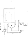
In Figur 1 ist beispielhaft der Aufbau einer Vorrichtung zur Durchführung des erfindungsgemäßen Verfahrens schematisch dargestellt. Durch ein Sprühsystem wird das gelierfähige Sol von unten nach oben in einem Winkel α von 80 bis 88°, in die Reaktionszone so eingesprüht, daß das Sol nach dem Verlassen des Sprühsystems erst unmittelbar vor oder beim Passieren der Eintrittsöffnung in die Reaktionszone in weitgehend gleichgroße Solperlen aufgerissen wird, wobei die Solperlen im Augenblick ihrer Bildung praktisch sofort der gelierenden Wirkung des Reaktionsgases ausgesetzt sind. Der Zerfall des Sols in einzelne Solperlen hängt neben dem Winkel dabei von der Viskosität des Sols, der jeweils eingesetzten Sprühvorrichtung sowie dem Druck, mit dem das Sol die Sprühvorrichtung verläßt, ab. Um den Punkt, an dem das Sol in einzelne Solperlen aufreißt, erfindungsgemäß einzustellen, wird der Abstand d zwischen Sprühvorrichtung und Eintrittsöffnung in die Reaktionszone zu Beginn des Sprühvorganges vom Fachmann durch Inaugenscheinnahme so variiert, d.h. der Abstand d vermindert oder ggf. vergrößert, bis der Aufreißpunkt des Sols in einzelne Solperlen sich unmittelbar vor oder in der Eintrittsöffnung zur Reaktionszone befindet.In Figure 1, the structure of a device for performing the method according to the invention is shown schematically by way of example. By means of a spray system, the gellable sol is sprayed into the reaction zone from bottom to top at an angle α of 80 to 88 °, so that the sol after leaving the spray system only immediately before or when it passes through the inlet opening into the reaction zone into largely identical size beads is torn open, the Solbeads are almost immediately exposed to the gelling effect of the reaction gas at the moment of their formation. In addition to the angle, the disintegration of the sol into individual sol beads depends on the viscosity of the sol, the spray device used in each case and the pressure with which the sol leaves the spray device. In order to adjust the point at which the sol tears into individual sol beads according to the invention, the distance d between the spray device and the inlet opening into the reaction zone at the beginning of the spraying process is varied by the person skilled in the art by inspection, i.e. the distance d is reduced or, if necessary, increased until the tearing point of the sol into individual sol beads is immediately in front of or in the inlet opening to the reaction zone.
Nach Eintritt in die Reaktionszone durchfliegen die gebildeten Solperlen eine in Form einer Parabel gekrümmte Flugbahn durch das sich in der Reaktionszone befindliche Reaktionsgas, wobei sie in ihrer Kugelform fixiert, d.h. vorverfestigt werden. Dadurch, daß die Solperlen diese parabelförmige Flugbahn durch das Reaktionsgas passieren müssen, kann das Reaktionsgas nach dem erfindungsgemäßen Verfahren besonders lange zur Vorverfestigung der Solperlen beitragen, sodaß dadurch die Gefahr der Deformation der Solperlen beim Auftreffen auf die Auffangvorrichtung bereits weitgehend minimiert ist. Durch zusätzliches Erwärmen der Reaktionszone, z.B. durch Erwärmen auf etwa 200°C, kann die Vorverfestigung der Teilchen gegebenenfalls noch weiter unterstützt werden. Um die Gefahr der Deformation noch weiter zu verringern, kann gewünschtenfalls eine in der Höhe verstellbare Auffangvorrichtung nahe an den Umkehrpunkt der parabelförmigen Flugbahn der Solperlen, an dem die Solperlen ihre geringste kinetische Energie besitzen, herangebracht werden.After entering the reaction zone, the sol beads formed fly through a trajectory curved in the form of a parabola through the reaction gas located in the reaction zone, where they are fixed in their spherical shape, ie are pre-consolidated. Due to the fact that the sol beads have to pass through this parabolic trajectory through the reaction gas, the reaction gas can contribute to the pre-solidification of the sol beads for a particularly long time, so that the risk of deformation of the sol beads when they strike the collecting device is largely minimized. The pre-solidification of the particles can optionally be further supported by additional heating of the reaction zone, for example by heating to about 200 ° C. In order to further reduce the risk of deformation, a height-adjustable collecting device can, if desired, be brought close to the reversal point of the parabolic trajectory of the sol beads, at which the sol beads have their lowest kinetic energy.
Als Auffangvorrichtung kann im erfindungsgemäßen Verfahren eine flachgezogene Folie, z.B. eine PVDF-Folie oder PE- oder PVC-Folie oder ein glattes Auffangblech oder ein mit Flüssigkeit gefüllter Auffangbehälter eingesetzt werden. Bei Verwendung eines glatten Auffangbleches kann dieses als solches gekühlt werden oder es kann ein gleichmäßig mit festem Kohlendioxid bedecktes Blech eingesetzt werden. Besonders bevorzugte Verfahrensvarianten verwenden als Auffangvorrichtung einen mit einer Flüssigkeit, z.B. mit Wasser oder vorzugsweise mit einer Reaktionsflüssigkeit gefüllten Auffangbehälter. Unter Reaktionsflüssigkeiten werden dabei alle üblichen sauren bzw. alkalischen Flüssigkeiten verstanden, wie sie üblicherweise für die Alterung von Teilchen nach dem Sol-Gel-Verfahren eingesetzt werden. Gebräuchliche Reaktionsflüssigkeiten sind hierfür z.B. wäßrige Ammoniaklösung, z.B. eine 5 bis 10 %ige wäßrige Ammoniaklösung, oder saure Reaktionsflüssigkeiten wie Salzsäure, Schwefelsäure oder Salpetersäure in Konzentrationen von 1 bis 5 Gew.-%. Bei Verwendung einer Reaktionsflüssigkeit sollten zweckmäßigerweise in der Reaktionszone hierzu äquivalente Reaktionsgase eingesetzt werden. Legt man als Reaktionsflüssigkeit z.B. eine wäßrige Ammoniaklösung vor, so sollten als Reaktionsgas Ammoniak-Gas oder Dämpfe organischer Amine eingesetzt werden. Bei Verwendung saurer Reaktionsflüssigkeiten wie Salzsäure, Schwefelsäure oder Salpetersäure sollten die hierzu äquivalenten sauren Reaktionsgase, also Chorwasserstoff, Schwefeldioxid bzw. Stickoxide verwendet werden.A flat-drawn film, for example a PVDF film or PE or PVC film or a smooth collecting plate or a collecting container filled with liquid, can be used as the collecting device in the method according to the invention. When using a smooth collecting plate, it can be cooled as such or a plate evenly covered with solid carbon dioxide can be used. Particularly preferred process variants use a collecting container filled with a liquid, for example with water or preferably with a reaction liquid, as the collecting device. Reaction liquids are understood to mean all customary acidic or alkaline liquids, as are usually used for the aging of particles by the sol-gel process. Common reaction liquids for this purpose are, for example, aqueous ammonia solution, for example a 5 to 10% strength aqueous ammonia solution, or acidic reaction liquids such as hydrochloric acid, sulfuric acid or nitric acid in concentrations of 1 to 5% by weight. When using a reaction liquid, equivalent reaction gases should expediently be used in the reaction zone. If, for example, an aqueous ammonia solution is provided as the reaction liquid, ammonia gas or vapors of organic amines should be used as the reaction gas. When using acidic reaction liquids such as hydrochloric acid, sulfuric acid or nitric acid, the equivalent acidic reaction gases, i.e. hydrogen chloride, sulfur dioxide or nitrogen oxides, should be used.
Das im erfindungsgemäßen Verfahren verwendete Reaktionsgas kann in der Reaktionszone als geschlossenem Behältnis über der entsprechenden Auffangvorrichtung leicht gehalten werden. Frisches Reaktionsgas kann dabei nach Bedarf ständig durch eine separate Gaszufuhr in die Reaktionszone nachgefüllt werden. Neben den bereits genannten alkalischen bzw. sauren Reaktionsgasen können bei der Verwendung selbstgelierender Sole als Reaktionsgase auch inerte Gase wie Luft oder Stickstoff eingesetzt werden, wobei gegebenenfalls hierbei die Vorverfestigung der Solteilchen durch Erwärmen der Reaktionszone auf Temperaturen von bis zu 1000°C oder höher, vorzugsweise 500 bis 800°C, unterstützt werden kann. Bei Verwendung von einem gleichmäßig mit festem Kohlendioxid bedeckten Auffangblech als Auffangvorrichtung kann die Reaktionszone gegebenenfalls auch auf Temperaturen unterhalb der Raumtemperatur gekühlt werden, um auf diese Weise durch Erniedrigung der Viskosität die Vorverfestigung der Solteilchen zu unterstützen.The reaction gas used in the process according to the invention can easily be kept in the reaction zone as a closed container above the corresponding collecting device. Fresh reaction gas can be refilled into the reaction zone by a separate gas supply as required. In addition to the alkaline or acidic reaction gases already mentioned, inert gases such as air or nitrogen can also be used as reaction gases when using self-gelling brine, with the solids being preferably pre-solidified by heating the reaction zone to temperatures of up to 1000 ° C. or higher, preferably 500 to 800 ° C, can be supported. If a collecting plate evenly covered with solid carbon dioxide is used as the collecting device, the reaction zone can, if appropriate, also be cooled to temperatures below room temperature in order to support the pre-consolidation of the sol particles by lowering the viscosity.
Von der Auffangvorrichtung können die vorverfestigten Solteilchen der Aufarbeitung, wie sie üblicherweise für nach dem Sol-Gel-Prozeß hergestellten Teilchen durchgeführt werden, zugeführt werden. Diese Aufarbeitung umfaßt üblicherweise die Aufarbeitungsschritte Waschen, Trocknen und ggf. Kalzinieren. So werden die Solteilchen üblicherweise bei Temperaturen im Bereich von 100 bis 200°C für eine Zeitdauer von 1 bis 24 Stunden getrocknet. In einer Variante können die vorverfestigten Solteilchen bei Verwendung einer flachgezogenen Folie oder eines glatten Auffangbleches als Auffangvorrichtung auch direkt in eine Trocknungseinheit, z.B. in einen an sich bekannten Sprühtrockner, überführt werden.The pre-solidified sol particles can be fed from the collecting device to the work-up as is usually carried out for particles produced by the sol-gel process. This workup usually includes the workup steps of washing, drying and optionally calcining. The sol particles are usually dried at temperatures in the range from 100 to 200 ° C. for a period of from 1 to 24 hours. In a variant, the pre-consolidated sol particles can also be used directly in a drying unit, e.g. when using a flat-drawn film or a smooth collecting plate as a collecting device. in a spray dryer known per se.
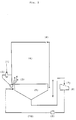
Zur Herstellung besonders kleiner Teilchen, insbesondere von Teilchen mit einem Durchmesser im Bereich von 0,001 mm bis 0,3 mm, wird in einer Abwandlung des erfindungsgemäßen Verfahrens zweckmäßigerweise eine Vorrichtung eingesetzt, wie sie schematisch in Figur 2 dargestellt ist. Diese Vorrichtung unterscheidet sich von der in Figur 1 dargestellten dadurch, daß sehr kleine Solperlen als Nebel von unten in die Reaktionszone eingesprüht werden. In dieser Verfahrensvariante werden durch eine Düse, zweckmäßigerweise eine Spiraldüse oder vorzugsweise eine Ultraschalldüse, die kleinen Solperlen als Nebel erzeugt, welche dann erfindungsgemäß von unten nach oben, z.B. mit einem aus Lüftungsanlagen bekannten Flügelventilator, in die das Reaktionsgas enthaltende Reaktionszone eingesprüht werden. Die weiteren Schritte erfolgen anschließend analog den Verfahrensschritten, wie sie oben bereits für die in Figur 1 dargestellte Verfahrensweise für größere Teilchen beschrieben sind.For the production of particularly small particles, in particular of particles with a diameter in the range from 0.001 mm to 0.3 mm, a device as shown schematically in FIG. 2 is expediently used in a modification of the method according to the invention. This device differs from that shown in FIG. 1 in that very small sol beads are sprayed into the reaction zone from below as a mist. In this variant of the process, the small sol beads are generated as a mist by a nozzle, expediently a spiral nozzle or, preferably, an ultrasonic nozzle, which then according to the invention are sprayed from bottom to top, for example with a fan known from ventilation systems, into the reaction zone containing the reaction gas. The further steps then take place analogously to the process steps as already described above for the procedure for larger particles shown in FIG. 1.
Die nach den vorstehenden Verfahrensvarianten erhaltenen kugelförmigen Teilchen können in einer weiteren Ausgestaltung dieser Verfahren noch einer Behandlung mit einem niederen Alkylalkohol, insbesondere einem C1- bis C4-Alkohol, wie z. B. Methanol, Ethanol, Propanol oder Isopropanol, oder einer Behandlung mit Aceton unterzogen werden, bevor sie nach dem Auffangen in der Auffangvorrichtung der Trocknung zugeführt werden. Vorzugsweise setzt man Isopropanol, welches möglichst wasserfrei sein sollte, für diese Behandlung ein. Durch die Behandlung mit einem niederen Alkylalkohol oder Aceton kann zum einen in vorteilhafter Weise ein Verkleben der erhaltenen Teilchen, insbesondere von Teilchen mit einem durchschnittlichen Durchmesser kleiner 1 mm, beim Trocknen vermieden werden, zum anderen kann durch diese Behandlung das Porenvolumen der erhaltenen Teilchen aufgeweitet werden. Hierfür werden die Teilchen aus der Auffangsvorrichtung in ein Behältnis überführt und für eine Zeitdauer von 1 Minute bis 24 Stunden, zweckmäßigerweise 2 bis 3 Stunden, mehrmals mit Alkohol überschichtet. So kann z.B. durch diese Behandlung das Porenvolumen auch von Aluminiumoxidteilchen gezielt verändert werden. So liegt z. B. das Porenvolumen von nach dem erfindungsgemäßen Verfahren hergestellten Aluminiumoxidteilchen nach Behandlung mit einem niederen Alkylalkohol im Bereich von 0,4 bis 2,5 ml/g (bestimmt nach dem Trocknen).In a further embodiment of these processes, the spherical particles obtained according to the above process variants can also be treated with a lower alkyl alcohol, in particular a C 1 - to C 4 -alcohol, such as. As methanol, ethanol, propanol or isopropanol, or a treatment with acetone before they are fed to the drying device after collection in the collecting device. Isopropanol, which should be as anhydrous as possible, is preferably used for this treatment. The treatment with a lower alkyl alcohol or acetone can, on the one hand, advantageously avoid sticking of the particles obtained, in particular particles with an average diameter of less than 1 mm, during drying, and on the other hand this treatment can widen the pore volume of the particles obtained . For this purpose, the particles are transferred from the collecting device into a container and covered with alcohol several times for a period of 1 minute to 24 hours, advantageously 2 to 3 hours. For example, this treatment can be used to specifically change the pore volume of aluminum oxide particles. So z. B. the pore volume of according to the invention Processed alumina particles after treatment with a lower alkyl alcohol in the range of 0.4 to 2.5 ml / g (determined after drying).
Durch das erfindungsgemäße Verfahren ist es in vorteilhafter Weise möglich, Teilchen auf der Basis anorganischer Oxide mit einer sehr gleichmäßigen Kugelgestalt, einer engen Verteilung der Porendurchmesser sowie einem sehr engen Kornspektrum zu erhalten. Hierbei kann der Anfall größerer Mengen an Unter- bzw. Überkorn weitgehend vermieden werden. Unter einem engen Kornspektrum wird dabei ein Kornspektrum verstanden, bei dem 80% der Teilchen einen Durchmesser innerhalb des in der nachfolgenden Tabelle angegebenen Bereichs um den jeweiligen mittleren Durchmesser aufweisen (Gaußverteilung).
Im erfindungsgemäßen Verfahren braucht kein Formöl eingesetzt zu werden, so daß die so hergestellten Teilchen frei von weiteren Verunreinigungen oder Verfärbungen sind. Auch läßt sich bei nach dem erfindungsgemäßen Verfahren hergestellten Teilchen durch eine Behandlung mit Aceton oder einem niederen Alkylalkohol vor dem Trocknen das Porenvolumen in vorteilhafter Weise aufweiten. Darüber hinaus zeigen die nach dem erfindungsgemäßen Verfahren hergestellten kugelförmigen Teilchen eine überraschend hohe Abriebfestigkeit.No molding oil needs to be used in the process according to the invention, so that the particles produced in this way are free from further impurities or discoloration. In the case of particles produced by the process according to the invention, treatment with acetone or a lower alkyl alcohol before drying also advantageously allows the pore volume to be expanded. In addition, the spherical particles produced by the process according to the invention show a surprisingly high abrasion resistance.
Durch das erfindungsgemäße Verfahren ist es moglich kugelförmige Teilchen auf Basis anorganischer Oxide zu erhalten, vorzugsweise auf Basis von Siliciumdioxid, Aluminiumoxid oder Alumosilikat, welche
- a) einen Durchmesser
im Bereich von 0,01bis 5 mm,vorzugsweise 0,02bis - b) eine spezifische Oberfläche
im Bereich von 1 bis 900 m2/g, vorzugsweise 100 bis 800 m2/g, - c) ein Schüttgewicht
im Bereich von bis 1,0 g/ml, - d) ein Porenvolumen
im Bereich von 0,25bis - e) eine Verteilung der Porendurchmesser mit einem Maximum (monomodale Porenverteilung) im Bereich von 15 bis 2000 Å, vorzugsweise 15 bis 400 Å,
- a) a diameter in the range from 0.01 to 5 mm, preferably 0.02 to 3.5 mm,
- b) a specific surface area in the range from 1 to 900 m 2 / g, preferably 100 to 800 m 2 / g,
- c) a bulk density in the range from 0.1 to 1.0 g / ml,
- d) a pore volume in the range from 0.25 to 2.5 ml / g,
- e) a distribution of the pore diameters with a maximum (monomodal pore distribution) in the range from 15 to 2000 Å, preferably 15 to 400 Å,
Die spezifische Oberfläche, das Porenvolumen und die Porenverteilung der Teilchen kann durch Quecksilber-Porosimetrie bzw. Aufnahme und Auswertung von Stickstoff-Sorptionskurven auf an sich bekannte Weise bestimmt werden. Das Maximum der Porendurchmesser und der mittlere Porendurchmesser lassen sich dann hieraus ermitteln.The specific surface area, the pore volume and the pore distribution of the particles can be determined in a manner known per se by mercury porosimetry or by recording and evaluating nitrogen sorption curves. The maximum pore diameter and the average pore diameter can then be determined from this.
Bevorzugt zeigen die Teilchen eine monomodale Porenverteilung, bei der 80 %, vorzugsweise 95 %, der Porendurchmesser der Formel 0,8 R ≤ R ≤ 1,2 R entsprechen, wobei R dem mittleren Porendurchmesser im Bereich von 15 bis 400 Å entspricht.The particles preferably have a monomodal pore distribution in which 80%, preferably 95%, of the pore diameter corresponds to the formula 0.8
Besonders bevorzugt sind dabei Teilchen auf der Basis von Aluminiumoxid, welche ein Porenvolumen im Bereich von 0,5 bis 2,5 ml/g, vorzugsweise 0,7 bis 2,5 ml/g, und einen mittleren Porendurchmesser R im Bereich von 60 bis 380 Å aufweisen.Particularly preferred are particles based on aluminum oxide, which have a pore volume in the range from 0.5 to 2.5 ml / g, preferably 0.7 to 2.5 ml / g, and an average pore diameter R in the range from 60 to Have 380 Å.
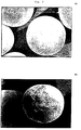
Die Teilchen können bevorzugt nach dem bereits angegebenen erfindungsgemäßen Verfahren hergestellt werden. Neben einer besonders gleichmäßigen Kugelform und engem Kornspektrum zeichnen die Teilchen sich durch ein hohes Porenvolumen bei einer ungewöhnlich engen Verteilung der Porendurchmesser aus. Hierbei ist besonders vorteilhaft, daß mindestens 80 %, vorzugsweise 95 % der Teilchen einen Porendurchmesser aufweisen, der im bereits angegebenen Toleranzbereich von 0,8 R ≤ R ≤ 1,2 R liegt. Der Anteil von Makroporen, d. h. von Poren mit einem Durchmesser von über 200 Å, liegt dabei unter 5 %. Die Teilchen weisen damit eine besonders homogene Oberfläche auf, was besonders für deren Verwendung als Katalysatorträger sehr vorteilhaft ist. In Figur 3A und 3B sind exemplarisch elektronenmikroskopische Aufnahmen der Oberflächen erfindungsgemäß hergestellter Teilchen dargestellt, die deren homogene gleichmäßige Oberflächenstruktur zeigen. Eine weitere besondere Eigenschaft der Teilchen besteht darin, daß sie bei ihrem hohen Porenvolumen eine überraschend hohe Abriebfestigkeit zeigen, was sie im Zusammenhang mit der hohen Schüttdichte besonders geeignet für die Verwendung als Katalysatoren oder Katalysatorträger in Fließbett- bzw. Wirbelschichtreaktoren macht.The particles can preferably be produced by the process according to the invention already specified. In addition to a particularly uniform spherical shape and a narrow grain spectrum, the particles are characterized by a high pore volume with an unusually narrow distribution of the pore diameters. It is particularly advantageous here that at least 80%, preferably 95% of the particles have a pore diameter which is within the tolerance range already specified of 0.8 R ≤ R ≤ 1.2 R. The proportion of macropores, ie pores with a diameter of over 200 Å, is less than 5%. The particles thus have a particularly homogeneous surface, which is particularly advantageous for their use as catalyst supports. FIGS. 3A and 3B show electron micrographs of the surfaces of particles produced according to the invention, which show their homogeneous, uniform surface structure. Another special property of the particles is that they have a surprisingly high abrasion resistance due to their high pore volume, which in connection with the high bulk density makes them particularly suitable for use as catalysts or catalyst supports in fluidized bed or fluidized bed reactors.
Weiterhin umfaßt die Erfindung die Verwendung der nach dem erfindungsgemäßen Verfahren hergestellten kugelförmigen Teilchen als Katalysatoren, Katalysatorträger, Ionenaustaucher, Adsorptions- und Trocknungsmittel.Furthermore, the invention comprises the use of the spherical particles produced by the process according to the invention as catalysts, catalyst supports, ion exchangers, adsorbents and drying agents.
So können z. B. mit Edelmetallen oder Übergangsmetallen dotierte Katalysatoren hergestellt werden, welche die nach dem erfindungsgemäßen Verfahren hergestellten Teilchen als Katalysatorträger enthalten. Beispielsweise können sie Edelmetalle wie Gold, Silber, Platin, Rhodium oder Palladium oder Übergangsmetalle wie Kupfer enthalten. Der Gehalt an solchen Metallen liegt üblicherweise im Bereich von 0,1 bis 5 Gew.-%, bezogen auf den fertigen Katalysatorträger. Weiterhin können auch Metallverbindungen, z. B. Oxide von Metallen, insbesondere Oxide von Übergangsmetallen, z. B. Oxide von Mangan, Eisen, Nickel oder Kobalt, enthalten sein. Natürlich können auch Gemische von Metallen, Gemische von Metallverbindungen oder Gemische von einem oder mehreren Metallen und einem oder mehreren Metallverbindungen auf dem Träger aufgebracht sein. Beispielsweise kann die Metallkomponente eines erfindungsgemäßen Katalysators aus Palladium und/oder Rhodium oder aus Palladium und Kupfer bestehen. Derartige Katalysatoren auf der Basis der Teilchen können z. B. in petrochemischen oder organisch-chemischen Synthese-Verfahren, z. B. in Oxidations-, Hydrier-, Oxichlorierungs- oder Polymerisationsverfahren, oder in katalytischen Verfahren zur Abwasser- und Abgasreinigung eingesetzt werden. Die Herstellung der erfindungsgemäßen Katalysatoren kann auf an sich bekannte Weise erfolgen. Beispielsweise kann man Metallsalze oder komplexe Metallverbindungen im Imprägnierverfahren, Sprühverfahren oder Fällungsverfahren auf die Teilchen aufbringen und nach Trocknung und Kalzinierung gewünschtenfalls reduzieren. Bevorzugt werden die Metalle durch ein Imprägnierverfahren, z. B. mit einer Lösung oder Suspension von Metallsalzen oder komplexen Metallverbindungen in Wasser oder einem organischen Lösungsmittel, auf die Teilchen aufgebracht. Ein Vorteil der auf Basis der erfindungsgemäß hergestellten Teilchen erhaltenen Katalysatoren ist deren hohe Abriebfestigkeit.So z. B. with noble metals or transition metals doped catalysts are prepared which contain the particles produced by the process according to the invention as a catalyst support. For example, they can contain noble metals such as gold, silver, platinum, rhodium or palladium or transition metals such as copper. The content of such metals is usually in the range from 0.1 to 5% by weight, based on the finished catalyst support. Furthermore, metal compounds, e.g. B. oxides of metals, especially oxides of transition metals, e.g. B. oxides of manganese, iron, nickel or cobalt may be included. Of course, mixtures of metals, mixtures of metal compounds or mixtures of one or more metals and one or more metal compounds can also be applied to the carrier. For example, the metal component of a catalyst according to the invention can consist of palladium and / or rhodium or of palladium and copper. Such catalysts based on the particles can e.g. B. in petrochemical or organic chemical synthesis processes, e.g. B. in oxidation, hydrogenation, oxychlorination or polymerization processes, or in catalytic processes for waste water and exhaust gas purification. The catalysts of the invention can be prepared in a manner known per se. For example, metal salts or complex metal compounds can be applied to the particles in the impregnation process, spray process or precipitation process and, if desired, reduced after drying and calcining. The metals are preferred by an impregnation process, e.g. B. with a solution or suspension of metal salts or complex metal compounds in water or an organic solvent, applied to the particles. An advantage of the catalysts obtained on the basis of the particles produced according to the invention is their high abrasion resistance.
Die nachfolgenden Beispiele sollen die Erfindung erläutern, ohne sie jedoch einzuschränken.The following examples are intended to explain the invention without, however, restricting it.
-
Figur 1:
Schematischer Aufbau einer Vorrichtung zur Durchführung des erfindungsgemäßen Verfahrens:- (1): Sol, (2): Pumpe, (3): Sprühvorrichtung, (4): Solstrahl, (5): Solperlen, (6): Reaktionszone mit Reaktionsgas, (7): Reaktionsgaszufuhr, (8): Auffangvorrichtung, (9): Sieb (fakultativ) (10): Sammelbehälter für die Teilchen, (11): Pumpe (fakultativ), (12): Rücklauf der Reaktionsflüssigkeit in den Auffangbehälter (fakultativ), α: Winkel α ; d: variabler Abstand zwischen Sprühvorrichtung und Eintrittsöffnung in die Reaktionszone
Schematic structure of a device for carrying out the method according to the invention:- (1): Sol, (2): Pump, (3): Spray device, (4): Sol jet, (5): Sol beads, (6): Reaction zone with reaction gas, (7): Reaction gas supply, (8): Collecting device, (9): sieve (optional) (10): collecting container for the particles, (11): pump (optional), (12): return of the reaction liquid into the collecting container (optional), α: angle α; d: variable distance between the spray device and the inlet opening into the reaction zone
-
Figur 2:
Schematischer Aufbau einer weiteren Vorrichtung zur Durchführung des erfindungsgemäßen Verfahrens für kleine Teilchen (0,001 bis 0,3 mm):- (1): Sol, (2): Sprühvorrichtung mit Zerstäuberdüse, (3): Nebel aus kleinen Solperlen, (4): Reaktionszone mit Reaktionsgas, (5): Auffangvorrichtung, (6): Reaktionsgaszufuhr, (7): Sieb (fakultativ), (8): Sammelbehälter, (9): Pumpe (fakultativ), (10) Rücklauf der Reaktionsflüssigkeit in den Auffangbehälter (fakultativ)
Schematic structure of a further device for carrying out the method according to the invention for small particles (0.001 to 0.3 mm):- (1): Sol, (2): spraying device with atomizing nozzle, (3): mist from small sol beads, (4): reaction zone with reaction gas, (5): collecting device, (6): reaction gas supply, (7): sieve (optional ), (8): collecting container, (9): pump (optional), (10) return of the reaction liquid into the collecting container (optional)
-
Figur 3:
Elektronenmikroskopische Aufnahmen zur Oberflächenbeschaffenheit erfindungsgemäß hergestellter Teilchen:- Figur 3A: Teilchen auf Basis von Alumosilikat mit 2,5 - 3,5 mm Durchmesser
- Figur 3B: Teilchen auf Basis von Siliciumdioxid mit 0,4 - 0,6 mm Durchmesser
Electron microscopic images of the surface properties of particles produced according to the invention:- Figure 3A: Particles based on aluminosilicate with a diameter of 2.5-3.5 mm
- Figure 3B: Particles based on silicon dioxide with a diameter of 0.4-0.6 mm
-
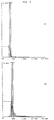
Figur 4 bis 8:
Diagramme der Porenradienverteilung erfindungsgemäß hergestellter Teilchen nach Quecksilber-Porosimetrie:
Es sind jeweils auf den Achsen aufgetragen:- x-Achse:
- Porenradius [Å]
- y-Achse:
- kumuliertes Porenvolumen [mm3/g]
Diagrams of the pore radius distribution of particles produced according to the invention by mercury porosimetry:
The following are plotted on the axes:- X axis:
- Pore radius [Å]
- y-axis:
- accumulated pore volume [mm 3 / g]
Die folgenden Beispiele 1 bis 8 wurden in einer Vorrichtung gemäß Fig. 1 durchgeführt.The following examples 1 to 8 were carried out in a device according to FIG. 1.
Nach dem erfindungsgemäßen Verfahren wurden kugelförmige Teilchen auf der Basis von Siliciumdioxid hergestellt. Hierfür wurden jeweils separat eine saure Lösung und eine alkalische Silikatlösung mit den in Tabelle 1 angegebenen Konzentrationen hergestellt. Als Füllstoffe wurden den Lösungen zusätzlich noch die ebenfalls in Tabelle 1 angegebenen Maischen zugefügt. Die saure bzw. alkalische Lösung wurde mit der entsprechenden Aerosil- bzw. SiO2-Maische im in Tabelle 1 angegebenen Volumenverhältnis zur jeweiligen sauren bzw. alkalischen Komponente vereinigt.Spherical particles based on silicon dioxide were produced by the process according to the invention. For this purpose, an acidic solution and an alkaline silicate solution with the concentrations given in Table 1 were prepared separately. The mashes also given in Table 1 were additionally added to the solutions as fillers. The acidic or alkaline solution was mixed with the corresponding Aerosil or SiO 2 mash in the volume ratio given in Table 1 combined to the respective acidic or alkaline component.
Die saure Komponente SK und die alkalische Komponente AK wurden in einer an sich bekannten Mischdüse bei einer Temperatur von ca. 10 °C miteinander vermischt und in einer Vorrichtung gemäß Fig. 1 sofort und kontinuierlich weiterverarbeit. Hierfür wurde das aus dem Zusammenmischen der beiden Komponenten unter einer Druckdifferenz von wenigstens 2 bar bei pH 6,4 erhaltene Sol über die Pumpe (2) und die Kanüle (3) (Durchmesser: 3,7 mm; Länge: 10 cm) mit einem Durchsatz von 4 l/min in einem Solstrahl (4) in die Reaktionszone (6) in der Weise eingesprüht, daß der Solstrahl (4) bei Eintritt in Reaktionszone (6) in Solperlen (5) aufriß. Nach dem Durchfliegen einer gekrümmten Flugbahn durch die das Reaktionsgas enthaltende Reaktionszone (6) wurden die Solperlen (5) in dem mit Reaktionsflüssigkeit gefüllten Auffangbehälter als Auffangvorrichtung (8) aufgefangen. Als Reaktionsgas wurde Ammoniak-Gas eingesetzt, welches über die Reaktionsgaszufuhr (7) ständig in die Reaktionszone (6) nachgefüllt wurde. Als Reaktionsflüssigkeit wurde eine wäßrige 5 %ige Ammoniak-Lösung eingesetzt.The acidic component SK and the alkaline component AK were mixed together in a mixing nozzle known per se at a temperature of approx. 10 ° C. and immediately and continuously processed in a device according to FIG. 1. For this purpose, the sol obtained by mixing the two components together under a pressure difference of at least 2 bar at pH 6.4 was pumped through the pump (2) and the cannula (3) (diameter: 3.7 mm; length: 10 cm) Throughput of 4 l / min in a sol jet (4) sprayed into the reaction zone (6) in such a way that the sol jet (4) broke into sol beads (5) when entering the reaction zone (6). After a curved trajectory had flown through the reaction zone (6) containing the reaction gas, the sol beads (5) were collected in the collecting container filled with reaction liquid as a collecting device (8). Ammonia gas was used as the reaction gas, which was continuously replenished into the reaction zone (6) via the reaction gas supply (7). An aqueous 5% ammonia solution was used as the reaction liquid.
Die Teilchen wurden etwa 30 Minuten in der wäßrigen Ammoniak-Lösung gealtert und anschließend über das Sieb (9) von der Reaktionsflüssigkeit getrennt und in den Sammelbehälter (10) überführt. Die Reaktionsflüssigkeit wurde über die Pumpe (11) durch den Rücklauf (12) wieder zurück in die Auffangvorrichtung (8) gepumpt.The particles were aged in the aqueous ammonia solution for about 30 minutes and then separated from the reaction liquid via the sieve (9) and transferred to the collecting container (10). The reaction liquid was pumped back into the collecting device (8) via the pump (11) through the return line (12).
Die erhaltenen Teilchen wurden anschließend auf an sich bekannte Weise einem Basenaustausch mit einer 0,5 %igen Ammoniumsulfatlösung unterzogen, bis zur Sulfatfreiheit gewaschen, für 18 Stunden bei 180 °C getrocknet und für 4 Stunden bei 600 °C getempert. Man erhielt kugelförmige Teilchen mit Durchmessern im Bereich von 2,5 bis 3,5 mm, deren Schüttdichte, spezifische Oberfläche und Porenvolumen in Tabelle 2 angegeben sind.
Nach dem erfindungsgemäßen Verfahren wurden kugelförmige Teilchen auf der Basis von Alumosilikat hergestellt.Spherical particles were obtained by the process according to the invention made on the basis of aluminosilicate.
Hierfür wurden jeweils separat eine saure Lösung A und eine alkalische Silikatlösung B hergestellt:
Die saure Lösung A und die alkalische Lösung B wurden in einer an sich bekannten Mischdüse bei einer Temperatur von ca 7 °C miteinander vermischt und in einer Vorrichtung gemäß Fig. 1 sofort und kontinuierlich weiterverarbeitet.The acidic solution A and the alkaline solution B were mixed together in a mixing nozzle known per se at a temperature of about 7 ° C. and immediately and continuously processed in a device according to FIG. 1.
Hierfür wurde das aus dem Zusammenmischen der beiden Komponenten unter einer Druckdifferenz von wenigstens 2 bar bei pH 8,3 erhaltene Sol über eine Kanüle von 3,7 mm Durchmesser und 10 cm Länge in einer Menge von 3,9 l/Minute in einem Solstrahl (4) in die Reaktionszone (6) in der Weise einsprüht, daß der Solstrahl (4) bei Eintritt in die Reaktionszone (6) in Solperlen (5) aufriß.For this purpose, the sol obtained by mixing the two components together under a pressure difference of at least 2 bar at pH 8.3 was sprayed through a cannula of 3.7 mm in diameter and 10 cm in length in a quantity of 3.9 l / minute in a sol jet ( 4) sprayed into the reaction zone (6) in such a way that the sol jet (4) broke into sol beads (5) when entering the reaction zone (6).
Nach dem Durchfliegen einer gekrümmten Flugbahn durch das Reaktionsgas wurden die Solperlen (5) in dem mit Reaktionsflüssigkeit gefüllten Auffangbehälter (8) aufgefangen. Als Reaktionsgas wurde HCl-Gas eingesetzt, welches über die Reaktionsgaszufuhr (7) ständig in die Reaktionszone (6) nachgefüllt wurde. Als Reaktionsflüssigkeit wurde eine wäßrige 2,5 %ige HCl-Lösung eingesetzt.After the reaction gas had flown through a curved trajectory, the sol beads (5) were collected in the collecting container (8) filled with reaction liquid. HCl gas was used as the reaction gas, which was continuously replenished into the reaction zone (6) via the reaction gas supply (7). An aqueous 2.5% HCl solution was used as the reaction liquid.
Die Teilchen wurden etwa 30 Minuten in der wäßrigen Chlorwasserstoff-Lösung gealtert und anschließend über das Sieb (9) von der Reaktionsflüssigkeit getrennt und in den Sammelbehälter (10) überführt. Die Reaktionsflüssigkeit wurde über die Pumpe (11) durch den Rücklauf (12) wieder zurück in die Auffangvorrichtung (8) gepumpt.The particles were aged in the aqueous hydrogen chloride solution for about 30 minutes and then separated from the reaction liquid via the sieve (9) and into the collecting container (10) transferred. The reaction liquid was pumped back into the collecting device (8) via the pump (11) through the return line (12).
Die erhaltenen Teilchen wurden anschließend auf an sich bekannte Weise einem Basenaustausch mit 0,5 %iger Schwefelsäurelösung unterzogen, gewaschen bis zur Sulfatfreiheit, für 18 Stunden bei 180 °C getrocknet und für 4 Stunden bei 200 °C getempert.The particles obtained were then subjected to a base exchange with a 0.5% strength sulfuric acid solution in a manner known per se, washed until free from sulfate, dried at 180 ° C. for 18 hours and annealed at 200 ° C. for 4 hours.
Man erhielt kugelförmige Alumosilikat-Teilchen mit Durchmessern im Bereich von 2,5 bis 3,5 mm, deren Schüttdichte, spezifische Oberfläche und Porenvolumen in der folgenden Tabelle 3 angegeben sind.
Ein metastabiles saures Aluminiumoxidhydratsol (Condea DisperalR 30/2) mit einer Zusammensetzung aus 14,19 Gew.-% Al2O3 und 85,81 Gew.-% Wasser wurde in einer Vorrichtung nach Fig. 1 mittels der Pumpe (2) bei einem Druck von 6 bar über 10 Kanülen (Durchmesser: 0,70 mm; Länge: 3,2 cm) mit einem Durchsatz von 0,75 l/Minute von unten nach oben versprüht, wobei die Solstrahlen bei Eintritt in die mit Ammoniakgas gefüllte Reaktionszone in eine Folge einzelner gleichgroßer Solperlen aufrissen.A metastable acidic aluminum oxide hydrate sol (Condea Disperal R 30/2) with a composition of 14.19% by weight Al 2 O 3 and 85.81% by weight water was in a device according to FIG. 1 by means of the pump (2) sprayed at a pressure of 6 bar via 10 cannulas (diameter: 0.70 mm; length: 3.2 cm) with a throughput of 0.75 l / minute from bottom to top, the sol jets entering the filled with ammonia gas Tear the reaction zone into a sequence of individual sol beads of the same size.
Nachfolgend sind die weiteren Reaktionsbedingungen angegeben:
- Vorlage:
- 5 %ige Ammoniaklösung
- Alterung:
- 1 h
- Trocknen:
- 8 h 120°
- Tempern:
- 4 h 600°
- Template:
- 5% ammonia solution
- Aging:
- 1 h
- Dry:
- 8 h 120 °
- Annealing:
- 4 h 600 °
Die erhaltenen Teilchen zeigten die folgenden Eigenschaften:The particles obtained had the following properties:
Einige der nach Beispiel 3 erhaltenen Teilchen wurden noch einer zusätzlichen Temperung unterzogen. In der nachfolgenden Tabelle 4 sind deren Eigenschaften dargestellt.
Kugelförmige Teilchen auf der Basis von Aluminiumoxid wurden wie in Beispiel 3 angegeben, hergestellt. Zusätzlich wurden diese Teilchen noch einer Behandlung mit wasserfreiem Isopropanol (Dichte: 0,785 g/ml) unterzogen. Für eine Zeitdauer von 2 Stunden wurden dafür die erhaltenen Teilchen vor dem Trocknen mit je 1 Liter Isopropanol pro 1 Liter Teilchen überschichtet. Bei einigen der Teilchen wurde die Isopropanol-Behandlung auch mehrfach durchgeführt, indem die Teilchen aus der Isopropanol-Lösung dekantiert wurden und anschließend wieder für die gleiche Zeitdauer in identischer Weise mit Isopropanol überschichtet wurden. Diese Isopropanol-Behandlung wurde bei einigen Teilchen bis zu achtmal hintereinander durchgeführt. Nach dem Trocknen und Kalzinieren, wie bereits in Beispiel 3 beschrieben, erhielt man Teilchen mit den in der nachfolgenden Tabelle angegebenen Eigenschaften.Spherical alumina-based particles were prepared as indicated in Example 3. In addition, these particles were subjected to a treatment with anhydrous isopropanol (density: 0.785 g / ml). For a period of For this purpose, the particles obtained were overlaid with 1 liter of isopropanol per 1 liter of particle before drying. For some of the particles, the isopropanol treatment was also carried out several times by decanting the particles from the isopropanol solution and then covering them again in an identical manner with isopropanol for the same period of time. This isopropanol treatment was carried out up to eight times in succession on some particles. After drying and calcining, as already described in Example 3, particles with the properties given in the table below were obtained.
Aus Tabelle 5 geht hervor, daß das Porenvolumen, das Schüttgewicht sowie der mittlere Porendurchmesser von nach dem erfindungsgemäßen Verfahren hergestellten Aluminiumoxid-Teilchen sich durch die zusätzliche Alkohol-Behandlung in weiten Bereichen variieren lassen.
Die Porenradienverteilung der Teilchen nach Beispiel 4a) ist in Fig. 6A), die nach Beispiel 4e in Fig. 6B) dargestellt.The pore radius distribution of the particles according to Example 4a) is shown in FIG. 6A), that according to Example 4e in FIG. 6B).
Ein metastabiles saures Aluminiumoxidhydratsol (Condea DisperalR 30/1) mit einer Zusammensetzung aus 18,00 Gew.-% Al2O3 und 82,00 Gew.-% Wasser wurde in einer Vorrichtung nach Fig. 1 mittels einer elektrisch angetriebenen Sprühpistole (Bullcraft N, 80W) mit einem Durchsatz von 0,060 l/Minute von unten nach oben in die mit Ammoniakgas gefüllte Reaktionszone eingesprüht. Nachfolgend sind die weiteren Reaktionsbedingungen sowie die Eigenschaften der erhaltenen Teilchen angegeben:
- Vorlage:
- 5 %ige Ammoniaklösung
- Alterung:
- 0,5 h
- Alkoholbehandlung:
- zweimal 2 h, Isopropanol
- Trocknen:
- 8 h 120°
- Tempern:
- 4 h 600°
- Durchmesser:
- 0,02 - 0,05 mm
- Schüttgewicht:
- 0,43 g/ml
- spezifische Oberfläche:
- 291 m2/g
- Porenvolumen:
- 1,19 ml/g
- Porenradienverteilung:
- dargestellt in Fig. 7A).
- Template:
- 5% ammonia solution
- Aging:
- 0.5 h
- Alcohol treatment:
- twice 2 h, isopropanol
- Dry:
- 8 h 120 °
- Annealing:
- 4 h 600 °
- Diameter:
- 0.02 - 0.05 mm
- Bulk density:
- 0.43 g / ml
- specific surface:
- 291 m 2 / g
- Pore volume:
- 1.19 ml / g
- Pore radius distribution:
- shown in Fig. 7A).
Ein metastabiles saures Aluminiumhydratsol (Versal R900) mit einer Zusammensetzung aus 15,35 Gew.-% Al2O3, 0,38 Gew.-% HNO3 und 84,27 Gew.-% Wasser wurde in einer Vorrichtung nach Figur 1 mittels Pumpe (2) bei einem Druck von 6 bar über 10 Kanülen (Durchmesser: 0,70 mm; Länge: 3,2 cm) wie bereits in Beispiel 3 beschrieben, mit einem Durchsatz von 0,75 l/Minute von unten nach oben versprüht.A metastable acid aluminum hydrate sol (Versal R 900) with a composition of 15.35% by weight Al 2 O 3 , 0.38% by weight HNO 3 and 84.27% by weight water was used in a device according to FIG. 1 by means of a pump (2) at a pressure of 6 bar via 10 cannulas (diameter: 0.70 mm; length: 3.2 cm) as already described in Example 3, with a throughput of 0.75 l / minute from bottom to top sprayed.
Nachfolgend sind die weiteren Reaktionsbedingungen angegeben:
- Vorlage:
- 5 %ige Ammoniaklösung
- Alterung:
- 1 h
- Trocknen:
- 10 h 180°C
- Tempern:
- 6 h 600°C
- Durchmesser:
- 0,4 - 0,6 mm
- Schüttgewicht:
- 0,66 g/ml
- spezifische Oberfläche:
- 190 m2/g
- Porenvolumen:
- 0,58 ml/g
- Porenradienverteilung:
- dargestellt in Fig. 7B)
- Template:
- 5% ammonia solution
- Aging:
- 1 h
- Dry:
- 10 h 180 ° C
- Annealing:
- 6 h 600 ° C
- Diameter:
- 0.4-0.6mm
- Bulk density:
- 0.66 g / ml
- specific surface:
- 190 m 2 / g
- Pore volume:
- 0.58 ml / g
- Pore radius distribution:
- shown in Fig. 7B)
Ein metastabiles Kieselsol (Bayer 200S, 30 % SiO2), angesäuert mit Salpetersäure bis auf pH4, wurde in einer Vorrichtung nach Fig. 1 mittels der Pumpe (2) bei einem Druck von 6,5 bar über 10 Kanülen (Durchmesser: 0,70 mm; Länge 3,20 cm) mit einem Durchsatz von 0,73 l/Minute von unten nach oben versprüht, wobei die Solstrahlen in die mit Ammoniakgas gefüllte Reaktionszone in gleichgroße Solperlen aufrissen. Nachfolgend sind die weiteren Reaktionsbedingungen sowie die Eigenschaften der erhaltenen Teilchen angegeben:
- Vorlage:
- 5 %ige Ammoniaklösung
- Alterung:
- 0,5 h
- Alkohol-Behandlung:
- zweimal 2 h, Isopropanol
- Trocknen:
- 8 h 120°
- Tempern:
- 4 h 200°
- Durchmesser:
- 0,4 - 0,6 mm
- Schüttgewicht:
- 0,49 g/ml
- spezifische Oberfläche:
- 297 m2/g
- Porenvolumen:
- 0,80 ml/g
- Porenradienverteilung:
- dargestellt in Fig. 8A)
- Oberflächenbeschaffenheit:
- dargestellt in Fig.3B)
- Template:
- 5% ammonia solution
- Aging:
- 0.5 h
- Alcohol treatment:
- twice 2 h, isopropanol
- Dry:
- 8 h 120 °
- Annealing:
- 4 h 200 °
- Diameter:
- 0.4-0.6mm
- Bulk density:
- 0.49 g / ml
- specific surface:
- 297 m 2 / g
- Pore volume:
- 0.80 ml / g
- Pore radius distribution:
- shown in Fig. 8A)
- Surface quality:
- shown in Fig.3B)
Nach dem erfindungsgemäßen Verfahren wurden kugelförmige Teilchen auf der Basis von Siliciumdioxid hergestellt.Spherical particles based on silicon dioxide were produced by the process according to the invention.
Hierfür wurden jeweils separat eine saure Lösung A und eine alkalische Silikatlösung B hergestellt:
Die saure Lösung A und die alkalische Lösung B wurden in einer an sich bekannten Mischdüse bei einer Temperatur von ca. 25°C miteinander vermischt und in einer Vorrichtung gemäß Figur 1 sofort und kontinuierlich weiterverarbeitet.The acidic solution A and the alkaline solution B were mixed together in a mixing nozzle known per se at a temperature of approximately 25 ° C. and immediately and continuously processed in a device according to FIG.
Hierfür wurde das aus dem Zusammenmischen der beiden Komponenten unter einer Druckdifferenz von wenigstens 2 bar bei pH 8,3 erhaltene Sol über eine gebräuchliche kommerziell erhältliche Spiraldüse (Firma Spraybest, Greenfield, USA) in einer Menge von 1,2 l/Minute in einem Solstrahl (4) in den Fällturm (6) in der Weise einsprüht, daß der Solstrahl (4) bei Eintritt in den Fällturm (6) in Solperlen (5) aufriß.For this purpose, the sol obtained by mixing the two components together under a pressure difference of at least 2 bar at pH 8.3 was passed through a customary commercially available spiral nozzle (Spraybest, Greenfield, USA) in an amount of 1.2 l / minute in a sol jet (4) sprayed into the trap tower (6) in such a way that the sol jet (4) broke into sol beads (5) when entering the trap tower (6).
Nach dem Durchfliegen einer gekrümmten Flugbahn durch das Reaktionsgas im Fällturm (6) wurden die Solperlen (5) in dem mit Reaktionsflüssigkeit gefüllten Auffangbehälter (8) aufgefangen. Als Reaktionsgas wurde HCl-Gas eingesetzt, welches über die Reaktionsgaszufuhr (7) ständig in den Fällturm (6) nachgefüllt wurde. Als Reaktionsflüssigkeit wurde eine wäßrige 2,5 %ige HCl-Lösung eingesetzt.After flying through a curved trajectory through the reaction gas in the trap tower (6), the sol beads (5) were collected in the collecting container (8) filled with reaction liquid. HCl gas was used as the reaction gas, which was constantly refilled into the trap tower (6) via the reaction gas supply (7). An aqueous 2.5% HCl solution was used as the reaction liquid.
Die Teilchen wurden etwa 30 Minuten in der wäßrigen Chlorwasserstoff-Lösung gealtert und anschließend über das Sieb (9) von der Reaktionsflüssigkeit getrennt und in den Sammelbehälter (10) überführt. Die Reaktionsflüssigkeit wurde über die Pumpe (11) durch den Rücklauf (12) wieder zurück in den Auffangbehälter (8) gepumpt.The particles were aged in the aqueous hydrogen chloride solution for about 30 minutes and then separated from the reaction liquid via the sieve (9) and transferred to the collecting container (10). The reaction liquid was pumped back into the collecting container (8) via the pump (11) through the return line (12).
Die erhaltenen Teilchen wurden anschließend auf an sich bekannte Weise einem Basenaustausch mit 0,5 %iger Schwefelsäurelösung unterzogen, gewaschen bis zur Sulfatfreiheit, für 18 Stunden bei 180°C getrocknet und dann unterschiedlich weiterverarbeitet, wie in der nachfolgenden Tabelle 6 dargestellt. Man erhielt kugelförmige Alumosilikat-Teilchen mit Durchmessern im Bereich von 0,9 bis 1,5 mm, deren Eigenschaften ebenfalls in Tabelle 6 aufgeführt sind.
Die Porenradienverteilung der gemäß Beispiel 8b erhaltenen Teilchen ist in Fig. 8B) dargestellt.The pore radius distribution of the particles obtained according to Example 8b is shown in Fig. 8B).
Die Abriebfestigkeit der nach Beispiel 1 bis 8 hergestellten Teilchen wurde nach folgendem Verfahren zur Bestimmung der relativen Abriebfestigkeit untersucht: jeweils 1,0 g der zu untersuchenden Teilchen wurden in ein 10 ml-Schnappdeckelglas (45 x 22 mm) eingewogen und zweimal mit 5 ml voll entsalztem Wasser (VE-Wasser) gespühlt, um eventuell anhaftenden Staub zu entfernen. Das oberflächlich anhaftende Wasser wurde dabei mit einer Kapillare abgesaugt, so daß lediglich das in den Poren befindliche Wasser an den Teilchen verblieb. Es wurden dann erneut 5 ml VE-Wasser zugegeben und das verschlossene Glas 1 Minute auf einem Reagenzglasschüttlier (Fa. Heidolf, Reax 1R) bei 2.400 U/min geschüttelt. 2 ml der überstehenden Lösung wurden dann sofort in eine 10 mm-Küvette überführt und der Extinktionswert E mehrfach nach wiederholtem Aufschütteln bei einer Wellenlänge von 500 µm (Spektralphotometer CADAS 100, Firma Dr. Lange) gemessen. Bei E-Werten, die größer als 1 waren, wurde die Probe entsprechend verdünnt, wobei die Linearität der Meßwerte gegeben war.The abrasion resistance of the particles produced according to Examples 1 to 8 was examined according to the following method for determining the relative abrasion resistance: 1.0 g in each case of the particles to be examined were weighed into a 10 ml snap-on glass jar (45 × 22 mm) and filled twice with 5 ml desalinated water (deionized water) to remove any dust that may have adhered to it. The water adhering to the surface was sucked off with a capillary so that only the water in the pores remained on the particles. A further 5 ml of demineralized water were then added and the sealed glass was shaken for 1 minute on a test tube shaker (Heidolf, Reax 1R) at 2,400 rpm. 2 ml of the supernatant solution were then immediately transferred into a 10 mm cuvette and the extinction value E was measured several times after repeated shaking at a wavelength of 500 μm (
Mechanisch stabile und damit abriebfeste Teilchen zeigen unter diesen Versuchsbedingungen E-Werte im Bereich von 0,1 bis 0,7.Mechanically stable and thus abrasion-resistant particles show E values in the range from 0.1 to 0.7 under these test conditions.
Die folgende Tabelle 7 zeigt die bei diesem Test erhaltenen Werte für die relative Abriebfestigkeit der nach Beispiel 1 bis 8 hergestellten Teilchen. Ebenfalls enthält die Tabelle 7 Vergleichswerte für die Abriebfestigkeit von Aluminiumoxid-Teilchen, die nach dem bisherigen Stand der Technik hergestellt wurden.
Claims (11)
- A method for producing abrasion-resistant, spherical particles having a monomodal pore distribution and a high pore volume on the basis of inorganic oxides by sol-gel conversion, characterised in that a sol is sprayed at an angle of 80 to 88° from below directly into a reaction zone containing a reaction gas such that the sol breaks up into individual sol beads immediately before or upon entry into the reaction zone, the sol beads flow through the reaction zone on a curved trajectory, in so doing are pre-consolidated and the sol beads are collected in a collecting means.
- A method according to Claim 1, characterised in that particles on the basis of inorganic oxides from the group magnesium oxide, aluminium oxide, silicon dioxide, alumosilicate, zinc oxide, titanium dioxide, chromium oxide, copper oxide, manganese oxide, cerium oxide, tin oxide, iron oxide, nickel oxide, lead oxide, molybdenum oxide, vanadium oxide, thorium oxide, zirconium oxide and/or hafnium oxide are produced.
- A method according to Claim 2, characterised in that particles on the basis of aluminium oxide and/or silicon dioxide or alumosilicate are produced.
- A method according to Claim 1, characterised in that particles having an average diameter in the range of 0.001 mm to 5 mm, measured after drying, are produced.
- A method according to Claim 1, characterised in that a foil or a smooth, optionally cooled, collecting plate or a collecting container filled with a liquid is used as collecting device.
- A method according to Claim 5, characterised in that a vessel filled with a reaction solution is used.
- A method according to Claim 6, characterised in that aqueous ammonia solution is used as reaction liquid and ammonia as reaction gas.
- A method according to Claim 6, characterised in that an aqueous acid from the group hydrochloric acid, sulphuric acid or nitric acid which is equivalent to the reaction gas is used and hydrogen chloride or sulphur dioxide or nitrogen oxide is used as reaction gas.
- A method according to Claim 1, characterised in that the sol contains fillers from the group silicic acids, alumosilicates, aluminium oxides, titanium dioxide, kaolin, montmorillonite, bentonite, zeolite, starch, wood flour or activated carbon.
- A method according to Claim 1, characterised in that the pre-consolidated sol beads are treated before drying with a lower alkyl alcohol and/or acetone.
- The use of the particles produced according to Claims 1 to 10 as catalysts, catalyst supports, ion-exchangers, adsorption agents or drying agents.
Applications Claiming Priority (5)
| Application Number | Priority Date | Filing Date | Title |
|---|---|---|---|
| DE4306875 | 1993-03-05 | ||
| DE4306875 | 1993-03-05 | ||
| DE4405202A DE4405202A1 (en) | 1993-03-05 | 1994-02-18 | Process for producing spherical particles |
| DE4405202 | 1994-02-18 | ||
| PCT/EP1994/000587 WO1994020203A1 (en) | 1993-03-05 | 1994-03-01 | Method of producing spherical particles |
Publications (2)
| Publication Number | Publication Date |
|---|---|
| EP0687199A1 EP0687199A1 (en) | 1995-12-20 |
| EP0687199B1 true EP0687199B1 (en) | 1997-06-04 |
Family
ID=25923665
Family Applications (2)
| Application Number | Title | Priority Date | Filing Date |
|---|---|---|---|
| EP94909897A Expired - Lifetime EP0690825B1 (en) | 1993-03-05 | 1994-03-01 | Catalytic treatment process for effluents containing organic and inorganic compounds, preferably from epichlorhydrine production |
| EP94909898A Expired - Lifetime EP0687199B1 (en) | 1993-03-05 | 1994-03-01 | Method of producing spherical particles |
Family Applications Before (1)
| Application Number | Title | Priority Date | Filing Date |
|---|---|---|---|
| EP94909897A Expired - Lifetime EP0690825B1 (en) | 1993-03-05 | 1994-03-01 | Catalytic treatment process for effluents containing organic and inorganic compounds, preferably from epichlorhydrine production |
Country Status (7)
| Country | Link |
|---|---|
| US (2) | US5676845A (en) |
| EP (2) | EP0690825B1 (en) |
| JP (2) | JPH08506988A (en) |
| AT (2) | ATE180754T1 (en) |
| DE (4) | DE59408365D1 (en) |
| DK (1) | DK0687199T3 (en) |
| WO (2) | WO1994020203A1 (en) |
Cited By (1)
| Publication number | Priority date | Publication date | Assignee | Title |
|---|---|---|---|---|
| CN106268733A (en) * | 2016-09-13 | 2017-01-04 | 山东大学 | A kind of monodimension nano stick is self-assembly of the preparation method of the Semen Castaneae shelly three-dimensional titanic oxide hollow microballoon with hierarchy |
Families Citing this family (19)
| Publication number | Priority date | Publication date | Assignee | Title |
|---|---|---|---|---|
| DE4406588A1 (en) * | 1994-03-01 | 1995-09-07 | Solvay Deutschland | Process for the catalytic treatment of waste water and a process for the regeneration of a catalyst |
| US5779915A (en) * | 1994-09-08 | 1998-07-14 | Solvay Umweltchemie Gmbh | Method of removing chlorine and halogen-oxygen compounds from water by catalytic reduction |
| DE4443884A1 (en) * | 1994-12-09 | 1996-06-13 | Solvay Deutschland | Process for the catalytic treatment of wastewater containing organic and inorganic compounds |
| US6492572B2 (en) * | 1995-08-29 | 2002-12-10 | E. I. Du Pont De Nemours And Company | Method for remediating contaminated soils |
| DE19748513C2 (en) * | 1997-11-03 | 1999-09-09 | Sueddeutsche Kalkstickstoff | Process for the adsorptive removal of hydrocarbons from aqueous hydrocyanic acid solutions |
| GB2331071A (en) * | 1997-11-11 | 1999-05-12 | Solvay | Manufacture of micro spherical zeolite containing catalyst particles |
| DE19757496A1 (en) * | 1997-12-23 | 1999-06-24 | Studiengesellschaft Kohle Mbh | Photocatalysts comprising metal oxide and metal ions |
| DE19810565A1 (en) | 1998-03-11 | 1999-09-16 | Basf Ag | Economical drying of microporous particles containing fluid e.g. inorganic, organic or polymer gel |
| KR20010079510A (en) * | 1999-05-19 | 2001-08-22 | 추후제출 | Method of decomposing organochlorine compound |
| DE10113113A1 (en) | 2001-03-16 | 2002-09-19 | Bayer Ag | Nitrate reduction through SO¶2¶ |
| WO2004092053A2 (en) * | 2003-04-09 | 2004-10-28 | Silicaglas Ilmenau Gmbh | Method for producing a siliceous granular material and the use of the same for producing a quartz glass granular material |
| US20040253386A1 (en) * | 2003-06-13 | 2004-12-16 | Sarojini Deevi | Preparation of intermetallics by metallo-organic decomposition |
| US20110300446A1 (en) * | 2010-06-03 | 2011-12-08 | Hon Hai Precision Industry Co., Ltd. | Lithium battery cathode composite material |
| JP7039853B2 (en) * | 2017-03-31 | 2022-03-23 | 戸田工業株式会社 | Amorphous aluminosilicate particle powder and its manufacturing method, slurry and molded product |
| CN108499572A (en) * | 2018-04-26 | 2018-09-07 | 华电高科环保技术有限公司 | Cellular low-temperature denitration catalyst and preparation method thereof |
| CN109046338B (en) * | 2018-08-03 | 2020-08-04 | 华中科技大学 | Carbon material immobilized palladium catalyst, preparation and application thereof |
| CN109126689B (en) * | 2018-09-27 | 2020-12-01 | 广西科学院 | Preparation method and application of modified montmorillonite |
| CN110180517B (en) * | 2019-06-28 | 2021-06-04 | 东北大学 | Preparation method of starch/polyethyleneimine composite magnetic adsorption material |
| CN112121813B (en) * | 2020-09-15 | 2023-05-30 | 北京山美水美臭氧高科技有限公司 | Alkaline earth metal modified Mn-based ozone oxidation catalyst and application thereof |
Family Cites Families (18)
| Publication number | Priority date | Publication date | Assignee | Title |
|---|---|---|---|---|
| DE359074C (en) * | 1922-09-18 | Gustav Hoehne | Snap fastener for curtains u. like | |
| US2467470A (en) * | 1945-05-25 | 1949-04-19 | Universal Oil Prod Co | Manufacture of spherical particles |
| US2652371A (en) * | 1949-12-20 | 1953-09-15 | Sinclair Refining Co | Process of forming spheroidal catalyst particles |
| AT207393B (en) * | 1957-02-14 | 1960-01-25 | Montedison Spa | Method and device for the production of grains, in particular from ammonium nitrate |
| US3233011A (en) * | 1961-04-06 | 1966-02-01 | Kurz Fredrik Wilhelm Anton | Methods of making a porous concrete structure |
| DE1592098C3 (en) * | 1965-12-13 | 1978-05-11 | Engelhard Minerals & Chemicals Corp., Murray Hill, N.J. (V.St.A.) | Process for the preparation of spherical alumina particles |
| FR1473239A (en) * | 1966-01-31 | 1967-05-29 | ||
| CH486273A (en) * | 1967-10-19 | 1970-02-28 | Max Kaltenbach Roger | Process for forming uniform droplets of a determined diameter, apparatus for carrying out this process and application of this process to the manufacture of a granulated product |
| US3840348A (en) * | 1971-05-10 | 1974-10-08 | Philadelphia Quartz Co | Crystallizing alkali metal contact with silicate droplets in countercurrent air flow |
| JPS515864A (en) * | 1974-07-03 | 1976-01-19 | Chisso Corp | ENSOKAKARUHONIRUKAGOBUTSUGANJUHAISUINO SHORIHOHO |
| JPS5437090A (en) * | 1977-07-13 | 1979-03-19 | Grace W R & Co | Catalyst manufacturing method |
| FR2527197B1 (en) * | 1982-05-19 | 1985-06-21 | Rhone Poulenc Spec Chim | PROCESS FOR THE MANUFACTURE OF ALUMINUM BEADS FORMED BY COAGULATION IN DROPS |
| US4758346A (en) * | 1985-10-28 | 1988-07-19 | Uop Inc. | Process for the removal of hydrocarbonaceous compounds from an aqueous stream and hydrogenating these compounds |
| US4909947A (en) * | 1986-03-03 | 1990-03-20 | Uop | Process for detoxifying high aqueous content hazardous waste streams |
| US4747937A (en) * | 1986-11-24 | 1988-05-31 | Uop Inc. | Process for the removal of hydrogenatable hydrocarbonaceous compounds from a hydrocarbonaceous stream and hydrogenating these compounds |
| DE3830850A1 (en) * | 1988-09-10 | 1990-03-22 | Gutec Gmbh | METHOD FOR REMOVING THE NITRITE AND / OR NITRATE CONTENT IN WATER |
| US4994422A (en) * | 1990-02-20 | 1991-02-19 | Fuel Conservation Corporation | Microspheres coated with catalyst and methods of producing same |
| DE4042594A1 (en) * | 1990-11-05 | 1992-07-02 | Nukem Gmbh | METHOD FOR PRODUCING ALUMINUM OXIDE BALLS |
-
1994
- 1994-03-01 WO PCT/EP1994/000587 patent/WO1994020203A1/en active IP Right Grant
- 1994-03-01 JP JP6518419A patent/JPH08506988A/en active Pending
- 1994-03-01 AT AT94909897T patent/ATE180754T1/en not_active IP Right Cessation
- 1994-03-01 WO PCT/EP1994/000586 patent/WO1994020423A1/en active IP Right Grant
- 1994-03-01 JP JP6518420A patent/JPH08506989A/en not_active Ceased
- 1994-03-01 DE DE59408365T patent/DE59408365D1/en not_active Expired - Fee Related
- 1994-03-01 DE DE4491190T patent/DE4491190D2/en not_active Expired - Fee Related
- 1994-03-01 DK DK94909898.2T patent/DK0687199T3/en active
- 1994-03-01 US US08/513,992 patent/US5676845A/en not_active Expired - Fee Related
- 1994-03-01 DE DE4491189T patent/DE4491189D2/en not_active Expired - Fee Related
- 1994-03-01 AT AT94909898T patent/ATE153875T1/en active
- 1994-03-01 US US08/513,885 patent/US5736118A/en not_active Expired - Fee Related
- 1994-03-01 EP EP94909897A patent/EP0690825B1/en not_active Expired - Lifetime
- 1994-03-01 DE DE59403026T patent/DE59403026D1/en not_active Expired - Fee Related
- 1994-03-01 EP EP94909898A patent/EP0687199B1/en not_active Expired - Lifetime
Cited By (2)
| Publication number | Priority date | Publication date | Assignee | Title |
|---|---|---|---|---|
| CN106268733A (en) * | 2016-09-13 | 2017-01-04 | 山东大学 | A kind of monodimension nano stick is self-assembly of the preparation method of the Semen Castaneae shelly three-dimensional titanic oxide hollow microballoon with hierarchy |
| CN106268733B (en) * | 2016-09-13 | 2018-11-30 | 山东大学 | A kind of monodimension nano stick is self-assembly of the preparation method of the shelly-shaped three-dimensional titanic oxide hollow microballoon of the chestnut with hierarchical structure |
Also Published As
| Publication number | Publication date |
|---|---|
| DE59408365D1 (en) | 1999-07-08 |
| DE4491190D2 (en) | 1995-04-27 |
| JPH08506989A (en) | 1996-07-30 |
| US5736118A (en) | 1998-04-07 |
| EP0690825B1 (en) | 1999-06-02 |
| EP0687199A1 (en) | 1995-12-20 |
| DK0687199T3 (en) | 1997-07-14 |
| US5676845A (en) | 1997-10-14 |
| DE59403026D1 (en) | 1997-07-10 |
| WO1994020423A1 (en) | 1994-09-15 |
| DE4491189D2 (en) | 1995-04-27 |
| JPH08506988A (en) | 1996-07-30 |
| EP0690825A1 (en) | 1996-01-10 |
| ATE180754T1 (en) | 1999-06-15 |
| WO1994020203A1 (en) | 1994-09-15 |
| ATE153875T1 (en) | 1997-06-15 |
Similar Documents
| Publication | Publication Date | Title |
|---|---|---|
| EP0687199B1 (en) | Method of producing spherical particles | |
| DE4042594C2 (en) | ||
| EP1331033B1 (en) | Highly active spherical metal support catalysts | |
| EP0742045A1 (en) | Cobalt catalysts | |
| DE112007001681T5 (en) | Process for producing NiO and Ni nanostructures | |
| DE2016838B2 (en) | Process for the production of granulated, abrasion-resistant, binder-free molecular sieve zeolites | |
| EP0226983B1 (en) | Iron containing catalyst for reducing the amount of nitrogen oxides in combustion gases | |
| EP0687198B1 (en) | Method of removing oxygen, nitrites and/or nitrates from water | |
| DE3242293A1 (en) | CATALYST SUPPORT IN THE FORM OF CALCINATED SPHERICAL TONER PARTICLES | |
| WO2009144034A1 (en) | Method for the production of nanocrystalline nickel oxides | |
| EP2527296A2 (en) | Adhesive-free zeolithic granulate with faujasite structure and method for producing such an adhesive-free zeolithic granulate and use of same | |
| DE69824033T2 (en) | PROCESS FOR PREPARING SPHERICAL CATALYST PARTICLES, CATALYST PARTICLES AND THEIR USE IN A CHEMICAL SYNTHESIS | |
| DE10013276A1 (en) | Preparation of porous silica beads, useful as catalyst, molecular sieve, ceramic raw material or adsorbent for useful or hazardous gas or ions, includes stirring alkoxysilane and alkylamine with aqueous acid and heating to remove amine | |
| DE4405202A1 (en) | Process for producing spherical particles | |
| DE2830101A1 (en) | PROCESS FOR MANUFACTURING CATALYSTS FOR HYDROCARBON CONVERSION | |
| DE4207961A1 (en) | ABRASION-RESISTANT CATALYST CARRIER | |
| EP0571317B1 (en) | Preparation of unbreakable sol-gel particles | |
| CN109718826B (en) | Microsphere Silicate-1 molecular sieve catalyst, preparation method thereof and method for preparing caprolactam | |
| DE69919284T3 (en) | COMPOSITION CONSISTING OF A LIQUID ABSORBED ON A CARRIERED SILICA BASE CARRIER | |
| DE4035089C1 (en) | Aluminium oxide spheres for adsorbent, chromatography, catalyst etc. - with defined surface area, density, pore vol, breaking strength and narrow particles size distribution etc. | |
| CN107930640B (en) | Catalyst for coproduction of 4-methyl-2-pentanone and 4-methyl-2-pentanol by one-step method | |
| DE4207959A1 (en) | Palladium and rhodium or copper catalyst impregnated in alumina carrier - for separating nitrites and/or nitrates from water, and having abrasion resistance | |
| DE4323085A1 (en) | Process for eliminating the oxygen, nitrite and/or nitrate content from water | |
| DE1442859C (en) | Process for the preparation of an attrition resistant crystalline silica, metal oxide and rare earth containing aluminosilicate catalyst | |
| DE1542451C3 (en) | Process for the preparation of a hydrocarbon conversion catalyst |
Legal Events
| Date | Code | Title | Description |
|---|---|---|---|
| PUAI | Public reference made under article 153(3) epc to a published international application that has entered the european phase |
Free format text: ORIGINAL CODE: 0009012 |
|
| 17P | Request for examination filed |
Effective date: 19951005 |
|
| AK | Designated contracting states |
Kind code of ref document: A1 Designated state(s): AT BE CH DE DK ES FR GB GR IE IT LI LU NL PT SE |
|
| 17Q | First examination report despatched |
Effective date: 19960220 |
|
| GRAG | Despatch of communication of intention to grant |
Free format text: ORIGINAL CODE: EPIDOS AGRA |
|
| GRAH | Despatch of communication of intention to grant a patent |
Free format text: ORIGINAL CODE: EPIDOS IGRA |
|
| GRAH | Despatch of communication of intention to grant a patent |
Free format text: ORIGINAL CODE: EPIDOS IGRA |
|
| GRAA | (expected) grant |
Free format text: ORIGINAL CODE: 0009210 |
|
| AK | Designated contracting states |
Kind code of ref document: B1 Designated state(s): AT BE CH DE DK ES FR GB GR IE IT LI LU NL PT SE |
|
| PG25 | Lapsed in a contracting state [announced via postgrant information from national office to epo] |
Ref country code: GR Free format text: LAPSE BECAUSE OF FAILURE TO SUBMIT A TRANSLATION OF THE DESCRIPTION OR TO PAY THE FEE WITHIN THE PRESCRIBED TIME-LIMIT Effective date: 19970604 Ref country code: ES Free format text: THE PATENT HAS BEEN ANNULLED BY A DECISION OF A NATIONAL AUTHORITY Effective date: 19970604 |
|
| REF | Corresponds to: |
Ref document number: 153875 Country of ref document: AT Date of ref document: 19970615 Kind code of ref document: T |
|
| REG | Reference to a national code |
Ref country code: CH Ref legal event code: EP |
|
| ITF | It: translation for a ep patent filed |
Owner name: ING. ZINI MARANESI & C. S.R.L. |
|
| REF | Corresponds to: |
Ref document number: 59403026 Country of ref document: DE Date of ref document: 19970710 |
|
| ET | Fr: translation filed | ||
| REG | Reference to a national code |
Ref country code: DK Ref legal event code: T3 |
|
| PG25 | Lapsed in a contracting state [announced via postgrant information from national office to epo] |
Ref country code: SE Effective date: 19970904 Ref country code: PT Effective date: 19970904 |
|
| GBT | Gb: translation of ep patent filed (gb section 77(6)(a)/1977) |
Effective date: 19970818 |
|
| PG25 | Lapsed in a contracting state [announced via postgrant information from national office to epo] |
Ref country code: LU Free format text: LAPSE BECAUSE OF NON-PAYMENT OF DUE FEES Effective date: 19980301 Ref country code: AT Free format text: LAPSE BECAUSE OF NON-PAYMENT OF DUE FEES Effective date: 19980301 |
|
| PG25 | Lapsed in a contracting state [announced via postgrant information from national office to epo] |
Ref country code: IE Free format text: LAPSE BECAUSE OF NON-PAYMENT OF DUE FEES Effective date: 19980330 |
|
| PG25 | Lapsed in a contracting state [announced via postgrant information from national office to epo] |
Ref country code: LI Free format text: LAPSE BECAUSE OF NON-PAYMENT OF DUE FEES Effective date: 19980331 Ref country code: CH Free format text: LAPSE BECAUSE OF NON-PAYMENT OF DUE FEES Effective date: 19980331 |
|
| REG | Reference to a national code |
Ref country code: IE Ref legal event code: FD4D Ref document number: 74530 Country of ref document: IE |
|
| PLBE | No opposition filed within time limit |
Free format text: ORIGINAL CODE: 0009261 |
|
| STAA | Information on the status of an ep patent application or granted ep patent |
Free format text: STATUS: NO OPPOSITION FILED WITHIN TIME LIMIT |
|
| 26N | No opposition filed | ||
| REG | Reference to a national code |
Ref country code: CH Ref legal event code: PL |
|
| REG | Reference to a national code |
Ref country code: GB Ref legal event code: IF02 |
|
| PGFP | Annual fee paid to national office [announced via postgrant information from national office to epo] |
Ref country code: GB Payment date: 20020227 Year of fee payment: 9 |
|
| PGFP | Annual fee paid to national office [announced via postgrant information from national office to epo] |
Ref country code: FR Payment date: 20020312 Year of fee payment: 9 |
|
| PGFP | Annual fee paid to national office [announced via postgrant information from national office to epo] |
Ref country code: DE Payment date: 20020314 Year of fee payment: 9 |
|
| PGFP | Annual fee paid to national office [announced via postgrant information from national office to epo] |
Ref country code: DK Payment date: 20020315 Year of fee payment: 9 |
|
| PGFP | Annual fee paid to national office [announced via postgrant information from national office to epo] |
Ref country code: NL Payment date: 20020328 Year of fee payment: 9 |
|
| PGFP | Annual fee paid to national office [announced via postgrant information from national office to epo] |
Ref country code: BE Payment date: 20020527 Year of fee payment: 9 |
|
| PG25 | Lapsed in a contracting state [announced via postgrant information from national office to epo] |
Ref country code: GB Free format text: LAPSE BECAUSE OF NON-PAYMENT OF DUE FEES Effective date: 20030301 |
|
| PG25 | Lapsed in a contracting state [announced via postgrant information from national office to epo] |
Ref country code: DK Free format text: LAPSE BECAUSE OF NON-PAYMENT OF DUE FEES Effective date: 20030331 Ref country code: BE Free format text: LAPSE BECAUSE OF NON-PAYMENT OF DUE FEES Effective date: 20030331 |
|
| BERE | Be: lapsed |
Owner name: *SOLVAY DEUTSCHLAND G.M.B.H. Effective date: 20030331 |
|
| PG25 | Lapsed in a contracting state [announced via postgrant information from national office to epo] |
Ref country code: NL Free format text: LAPSE BECAUSE OF NON-PAYMENT OF DUE FEES Effective date: 20031001 Ref country code: DE Free format text: LAPSE BECAUSE OF NON-PAYMENT OF DUE FEES Effective date: 20031001 |
|
| GBPC | Gb: european patent ceased through non-payment of renewal fee | ||
| PG25 | Lapsed in a contracting state [announced via postgrant information from national office to epo] |
Ref country code: FR Free format text: LAPSE BECAUSE OF NON-PAYMENT OF DUE FEES Effective date: 20031127 |
|
| NLV4 | Nl: lapsed or anulled due to non-payment of the annual fee |
Effective date: 20031001 |
|
| REG | Reference to a national code |
Ref country code: FR Ref legal event code: ST |
|
| PG25 | Lapsed in a contracting state [announced via postgrant information from national office to epo] |
Ref country code: IT Free format text: LAPSE BECAUSE OF NON-PAYMENT OF DUE FEES Effective date: 20050301 |