EP0686791B1 - Protective bellows - Google Patents
Protective bellows Download PDFInfo
- Publication number
- EP0686791B1 EP0686791B1 EP95300056A EP95300056A EP0686791B1 EP 0686791 B1 EP0686791 B1 EP 0686791B1 EP 95300056 A EP95300056 A EP 95300056A EP 95300056 A EP95300056 A EP 95300056A EP 0686791 B1 EP0686791 B1 EP 0686791B1
- Authority
- EP
- European Patent Office
- Prior art keywords
- bellows
- turns
- diameter
- turn
- skirt portion
- Prior art date
- Legal status (The legal status is an assumption and is not a legal conclusion. Google has not performed a legal analysis and makes no representation as to the accuracy of the status listed.)
- Revoked
Links
- 230000001681 protective effect Effects 0.000 title claims description 8
- 230000015572 biosynthetic process Effects 0.000 claims 1
- 230000006835 compression Effects 0.000 description 1
- 238000007906 compression Methods 0.000 description 1
Images


Classifications
-
- F—MECHANICAL ENGINEERING; LIGHTING; HEATING; WEAPONS; BLASTING
- F16—ENGINEERING ELEMENTS AND UNITS; GENERAL MEASURES FOR PRODUCING AND MAINTAINING EFFECTIVE FUNCTIONING OF MACHINES OR INSTALLATIONS; THERMAL INSULATION IN GENERAL
- F16J—PISTONS; CYLINDERS; SEALINGS
- F16J3/00—Diaphragms; Bellows; Bellows pistons
- F16J3/04—Bellows
- F16J3/041—Non-metallic bellows
- F16J3/042—Fastening details
-
- F—MECHANICAL ENGINEERING; LIGHTING; HEATING; WEAPONS; BLASTING
- F16—ENGINEERING ELEMENTS AND UNITS; GENERAL MEASURES FOR PRODUCING AND MAINTAINING EFFECTIVE FUNCTIONING OF MACHINES OR INSTALLATIONS; THERMAL INSULATION IN GENERAL
- F16C—SHAFTS; FLEXIBLE SHAFTS; ELEMENTS OR CRANKSHAFT MECHANISMS; ROTARY BODIES OTHER THAN GEARING ELEMENTS; BEARINGS
- F16C11/00—Pivots; Pivotal connections
- F16C11/04—Pivotal connections
- F16C11/06—Ball-joints; Other joints having more than one degree of angular freedom, i.e. universal joints
- F16C11/0666—Sealing means between the socket and the inner member shaft
- F16C11/0671—Sealing means between the socket and the inner member shaft allowing operative relative movement of joint parts due to flexing of the sealing means
-
- F—MECHANICAL ENGINEERING; LIGHTING; HEATING; WEAPONS; BLASTING
- F16—ENGINEERING ELEMENTS AND UNITS; GENERAL MEASURES FOR PRODUCING AND MAINTAINING EFFECTIVE FUNCTIONING OF MACHINES OR INSTALLATIONS; THERMAL INSULATION IN GENERAL
- F16C—SHAFTS; FLEXIBLE SHAFTS; ELEMENTS OR CRANKSHAFT MECHANISMS; ROTARY BODIES OTHER THAN GEARING ELEMENTS; BEARINGS
- F16C33/00—Parts of bearings; Special methods for making bearings or parts thereof
- F16C33/72—Sealings
- F16C33/726—Sealings with means to vent the interior of the bearing
Definitions
- the invention relates to protective bellows.
- a protective bellows embodying the invention is for protecting the steering mechanism of a motor vehicle.
- Protective bellows according to preamble of claim 1 are known from FR-A-2687753 or EP-A-327347.
- a protective bellows for protecting an axially movable member which has an angularly movable end portion, comprising integral fixing means for fixing one end of the bellows to mounting means with respect to which the member is axially movable, and integral fixing means for fixing the other end of the bellows to the angularly movable end portion of the member, characterized in that the bellows incorporates a substantially axially directed skirt portion sized to seat itself and be located on the part of the axially movable member adjacent its junction with the angularly movable end portion, the bellows having a first plurality of bellows turns extending between one fixing means and the skirt portion and a second plurality of bellows turns extending between the skirt portion and the other fixing means, the bellows turns remaining out of contact with the remaining portions of said member and of its end portion.
- a protective bellows for protecting an axially movable rod member of a steering mechanism which carries a joint connected to a rod end linked to a steerable road wheel of the vehicle, the joint permitting the rod end to move angularly with respect to the axially movable rod member
- the bellows comprising a first fixing collar at one of its ends for securing that end to the steering mechanism from which extends the axially movable rod member, a second fixing collar at the other of its ends for securing that end to the angularly movable rod end, and an intermediate generally cylindrically shaped skirt portion which contacts the outside of the joint
- the bellows also incorporating a first plurality of bellows turns extending integrally between the first fixing collar and one axial end of the skirt portion and a second plurality of bellows turns extending from the other axial end of the skirt portion to the second fixing collar.
- Figure 1 shows a known form of bellows 10 fitted in position on the steering mechanism 12 of a motor vehicle.
- the bellows 10 extends between two fixing collars 14 and 20.
- Fixing collar 14 is secured to a circumferential mounting surface 16 forming the end of a casing 17 of the steering mechanism.
- Fixing 20 is secured to the end 22 of the steering rod 18 of the steering mechanism.
- the collars 14 and 20 may be clamped in position by clamping rings not shown.
- the longitudinal or axial position of the rod 18 is adjusted by the mechanical or hydraulic mechanism within the casing 17 and transmits its movement to one of the front wheels of the vehicle to which it is connected by the rod end 22.
- the rod end 22 can move angularly relative to the rod 18, being connected to the rod 18 by a joint 26.
- a similar rod projects from the other end of the casing 17 and is similarly adjusted, and, in turn, adjusts the position of the other front road wheel.
- a similar bellows is fitted at that end of the casing.
- the bellows 10 comprises a plurality of substantially identical bellows turns 10A,10B,10C...10M which extend from the fixing collar 14 towards the fixing collar 20.
- the final bellows turn 10M is connected to the fixing collar 20 by an extension 24 of this turn, the extension 24 taking account of the difference in diameter between the two fixing collars 14 and 20.
- Figure 2 shows the configuration adopted by the known bellows 10 when the rod end 22 is turned through a sharp angle. As indicated, this causes the extension 24 to exert a pull on the adjacent bellows turns 10L and 10M, buckling and distorting them and bringing the troughs of these turns into, or nearly into, contact with the outside of the casing of the joint 26. This buckling and distortion, and partial contact with the end cap 26, is unsatisfactory.
- the bellows 28 embodying the invention has fixing collars 30 and 32 corresponding to the fixing collars 14 and 20 of the bellows of Figures 1 and 2.
- the bellows 28 is arranged in two portions A and B which are integrally interconnected by a skirt portion 34.
- the portion A of the bellows is made up of bellows turns 28A,28B,28C.... 28K, the last turn 28K having an extension 36 which is connected to the skirt portion 34 by a trough 38.
- the portion B comprises bellows turns 28L,28M and 28N.
- Bellows turn 28L is connected to the skirt portion 34 by a shallow trough 40.
- Bellows turn 28N has an extension portion 42 which is connected to the fixing collar 32.
- the skirt portion 34 is cylindrical in shape and is sized so as to seat itself on the outside of the casing 26.
- the troughs 38 and 40 locate the skirt portion on the casing 26 and provide a clamping action.
- the number of bellows turns within the portions A and B can be varied as necessary.
- the bellows turns 28A... 28K of the portion 28 are arranged so that the peaks of alternate turns have the same diameter as each other but this diameter is different from the diameter of the peaks of the intervening turns. Similarly, the troughs of alternate turns have the same diameter but this diameter is different from the diameter of the intervening turns. Therefore, when the rod 18 moves to the left (as viewed in the Figures) relative to the casing 17, thus compressing the turns 28, the peaks of adjacent turns do not come into contact with each other (because they are of different diameter); similarly, the troughs of adjacent turns do not come into contact with each other. This reduces the pressure generated between adjacent bellows turns.
- Figure 4 shows the configuration which the bellows 28 adopts when the rod end 22 is turned through a sharp angle. Because the skirt portion 34 is always in contact with the outside of the joint 26, substantially no distortion or buckling of the bellows occurs. The bellows turns over the portion A are substantially unaffected by the angularity of the rod end 22. The angularity of the rod end 22 is accommodated by the bellows turns in the portion B.
- the bellows turns within the portion A are shown as having a cylindrical generatrix. However, instead they may have a slightly conical generatrix.
- the bellows turns within the portion B can be similarly arranged.
- the outer diameter of the bellows turns 28L to 28N is preferably between 0.7 and 1.2 times the outer diameter of the skirt portion 34.
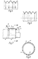
- Figures 5 and 6 show different arrangements of bellows turns within the portion 28 of the bellows of Figures 3 and 4.
- alternative bellows turns have the same outer diameter but this diameter differs from the outer diameter of the peaks of the intervening turns.
- all the troughs have the same diameter.
- all the peaks have the same diameter, in contrast to the bellows of Figures 3 and 4, but the troughs of alternate turns have a diameter which differs from the diameter of the intervening turns.
- the arrangements of Figures 5 and 6 thus provide at least a partial reduction of the pressure which each turn exerts on the next turn during compression of the bellows.
- an air passage 60 may interconnect the two regions.
- Figure 8 shows how the air passage 60 may be produced by forming a groove in the material of the skirt 34. A second groove may be provided to constitute a second air passage 62.
Landscapes
- Engineering & Computer Science (AREA)
- General Engineering & Computer Science (AREA)
- Mechanical Engineering (AREA)
- Diaphragms And Bellows (AREA)
- Sealing Devices (AREA)
- Joints That Cut Off Fluids, And Hose Joints (AREA)
Description
Claims (10)
- A protective bellows for protecting an axially movable member (18) which has an angularly movable end portion (22), comprising integral fixing means (30) for fixing one end of the bellows to mounting means (16) with respect to which the member (18) is axially movable, and integral fixing means (32) for fixing the other end of the bellows to the angularly movable end portion (22) of the member (18), characterised in that the bellows incorporates a substantially axially directed skirt portion (34) sized to seat itself and be located on the part (26) of the axially movable member (18) adjacent its junction with the angularly movable end portion (22), the bellows having a first plurality of bellows turns (A) extending between one fixing means (30) and the skirt portion (34) and a second plurality of bellows turns (B) extending between the skirt portion (34) and the other fixing means (32), the bellows turns remaining out of contact with the remaining portions of said member (18) and of its end portion (22).
- A bellows according to claim 1, characterised in that the skirt portion (34) incorporates at least one radially directed at least partially circumferentially extending formation for locating the skirt portion axially with respect to the said part (26) of the member.
- A bellows according to claim 1 or 2, characterised in that the axially movable member (18) is a rod member of a steering mechanism which carries a joint connected to a rod end (22) which is linked to a steerable road wheel of a vehicle and which constitutes the angularly movable end portion (22).
- A bellows according to any preceding claim, characterised by means defining an air passage (60,62) extending between two portions (12,52) within the interior of the bellows which are otherwise separated from each other by contact of the skirt portion (34) with the said part (26) of the member.
- A bellows according to any preceding claim, characterised in that there is a relatively large number of bellows turns in the first plurality (A) and a relatively small number of bellows turns in the second plurality (B).
- A bellows according to any preceding claim, characterised in that adjacent bellows turns in the first plurality (A) are differently sized so as to reduce compressive forces acting therebetween when the bellows is longitudinally compressed by axial movement of the said member (18).
- A bellows according to any of claims 1 to 5, characterised in that the diameter of the peak of each bellows turn in the first plurality (A) differs from the diameter of the peak of the adjacent bellows turn.
- A bellows according to claim 6 or 7, characterised in that the diameter of the trough of each bellows turn of the first plurality (A) differs from the diameter of the trough of the adjacent bellows turn.
- A bellows according to any one of claims 6 to 8, characterised in that the diameter of the peak of each bellows turn of the first plurality (A) is substantially the same as the diameter of the peak of the next alternate bellows turn of that plurality.
- A bellows according to any one of claims 6 to 9, characterised in that the diameter of the trough of each bellows turn of the first plurality (A) is the same as the diameter of the trough of the next alternate bellows turn of that plurality.
Applications Claiming Priority (2)
| Application Number | Priority Date | Filing Date | Title |
|---|---|---|---|
| GB9403587 | 1994-02-24 | ||
| GB9403587A GB2287290B (en) | 1994-02-24 | 1994-02-24 | Protective bellows |
Publications (2)
| Publication Number | Publication Date |
|---|---|
| EP0686791A1 EP0686791A1 (en) | 1995-12-13 |
| EP0686791B1 true EP0686791B1 (en) | 1998-06-10 |
Family
ID=10750882
Family Applications (1)
| Application Number | Title | Priority Date | Filing Date |
|---|---|---|---|
| EP95300056A Revoked EP0686791B1 (en) | 1994-02-24 | 1995-01-05 | Protective bellows |
Country Status (5)
| Country | Link |
|---|---|
| EP (1) | EP0686791B1 (en) |
| JP (1) | JPH07259995A (en) |
| DE (1) | DE69502882T2 (en) |
| ES (1) | ES2116677T3 (en) |
| GB (1) | GB2287290B (en) |
Families Citing this family (5)
| Publication number | Priority date | Publication date | Assignee | Title |
|---|---|---|---|---|
| GB2320067A (en) * | 1996-12-09 | 1998-06-10 | Courtaulds Fibres | Pump seals |
| KR101491438B1 (en) * | 2014-08-29 | 2015-02-09 | 김용수 | Joint bellows for semiconductor Making Facilities |
| CN104816758A (en) * | 2015-05-15 | 2015-08-05 | 豫北转向系统股份有限公司 | Automobile steering device seal structure |
| CN105946963A (en) * | 2016-05-11 | 2016-09-21 | 新乡艾迪威汽车科技有限公司 | Sealing structure between an automobile steering device and an automobile firewall |
| DE102017110164A1 (en) * | 2017-05-11 | 2018-11-15 | Schaeffler Technologies AG & Co. KG | Bellows binding in the release system area |
Family Cites Families (8)
| Publication number | Priority date | Publication date | Assignee | Title |
|---|---|---|---|---|
| DE2205798B1 (en) * | 1972-02-08 | 1973-01-04 | Uni-Cardan Ag, 5204 Lohmar | Sleeve for sealing a constant velocity swivel joint |
| DE3140542C1 (en) * | 1981-10-13 | 1983-04-07 | Uni-Cardan Ag, 5200 Siegburg | Sealing arrangement |
| DE3309386C1 (en) * | 1983-03-16 | 1984-10-18 | Fa. Carl Freudenberg, 6940 Weinheim | Sealing sleeve |
| JPS61109967A (en) * | 1984-10-31 | 1986-05-28 | Tokai T R W Kk | Bellows |
| DE3641393C1 (en) * | 1986-12-04 | 1988-03-17 | Daimler Benz Ag | Bellows |
| GB8802537D0 (en) * | 1988-02-04 | 1988-03-02 | Adwest Eng Ltd | Bellows/gaiter seal for rack & pinion steering mechanism |
| GB2262142B (en) * | 1991-12-03 | 1995-04-19 | Draftex Ind Ltd | Protective bellows |
| DE4205678C2 (en) * | 1992-02-25 | 1995-04-13 | Loehr & Bromkamp Gmbh | Bellows |
-
1994
- 1994-02-24 GB GB9403587A patent/GB2287290B/en not_active Expired - Fee Related
-
1995
- 1995-01-05 EP EP95300056A patent/EP0686791B1/en not_active Revoked
- 1995-01-05 DE DE69502882T patent/DE69502882T2/en not_active Revoked
- 1995-01-05 ES ES95300056T patent/ES2116677T3/en not_active Expired - Lifetime
- 1995-02-22 JP JP7033900A patent/JPH07259995A/en active Pending
Also Published As
| Publication number | Publication date |
|---|---|
| GB9403587D0 (en) | 1994-04-13 |
| DE69502882T2 (en) | 1998-11-26 |
| DE69502882D1 (en) | 1998-07-16 |
| EP0686791A1 (en) | 1995-12-13 |
| ES2116677T3 (en) | 1998-07-16 |
| GB2287290B (en) | 1996-06-26 |
| JPH07259995A (en) | 1995-10-13 |
| GB2287290A (en) | 1995-09-13 |
Similar Documents
| Publication | Publication Date | Title |
|---|---|---|
| US6948728B2 (en) | Suspension strut bearing for a suspension strut | |
| US5193433A (en) | Piston sealing and dampening device | |
| US4597745A (en) | Elastic protective bellows for a homokinetic transmission joint | |
| US6050174A (en) | Vacuum servo brake for motor vehicles | |
| US4530506A (en) | Sealing cap for cylindrical parts, especially for a bolt guide of a spot-type disk brake | |
| GB2310475A (en) | Shock absorber | |
| GB2070737A (en) | Drive coupling | |
| EP1002469B1 (en) | Glove of rubber or the like | |
| US5090298A (en) | Brake booster with sealed passage for mounting | |
| GB2222213A (en) | Hydraulic cylinder | |
| GB2119455A (en) | Elastomeric sealing boot | |
| EP0364411B1 (en) | Suspension device for vehicles, comprising a telescopic shock absorber and an air spring | |
| GB2026131A (en) | Elastic support for motor vehicle suspension | |
| GB2040243A (en) | Steering wheels | |
| US6029960A (en) | Hydraulically damping elastic bearing | |
| GB2295426A (en) | Protective bellows | |
| EP0686791A1 (en) | Protective bellows | |
| GB2262142A (en) | Protective bellows | |
| GB2024968A (en) | Servo boosters for vehicle braking systms | |
| GB2079885A (en) | Guard assembly for transmission shaft | |
| GB2103757A (en) | Improvements in bushes | |
| US6408623B1 (en) | Simplified hydraulic control device for a clutch, especially for an automobile | |
| US5129137A (en) | Method of mounting a spring seat on a hydraulic damping device | |
| US6254131B1 (en) | Motor vehicle steering column arrangement with space-saving holder for adjustment | |
| GB2231377A (en) | Vacuum brake power booster |
Legal Events
| Date | Code | Title | Description |
|---|---|---|---|
| PUAI | Public reference made under article 153(3) epc to a published international application that has entered the european phase |
Free format text: ORIGINAL CODE: 0009012 |
|
| AK | Designated contracting states |
Kind code of ref document: A1 Designated state(s): DE ES FR IT |
|
| 17P | Request for examination filed |
Effective date: 19960315 |
|
| GRAG | Despatch of communication of intention to grant |
Free format text: ORIGINAL CODE: EPIDOS AGRA |
|
| 17Q | First examination report despatched |
Effective date: 19971022 |
|
| GRAG | Despatch of communication of intention to grant |
Free format text: ORIGINAL CODE: EPIDOS AGRA |
|
| GRAH | Despatch of communication of intention to grant a patent |
Free format text: ORIGINAL CODE: EPIDOS IGRA |
|
| GRAH | Despatch of communication of intention to grant a patent |
Free format text: ORIGINAL CODE: EPIDOS IGRA |
|
| RAP1 | Party data changed (applicant data changed or rights of an application transferred) |
Owner name: DRAFTEX INDUSTRIES LIMITED |
|
| ITF | It: translation for a ep patent filed | ||
| GRAA | (expected) grant |
Free format text: ORIGINAL CODE: 0009210 |
|
| AK | Designated contracting states |
Kind code of ref document: B1 Designated state(s): DE ES FR IT |
|
| REF | Corresponds to: |
Ref document number: 69502882 Country of ref document: DE Date of ref document: 19980716 |
|
| REG | Reference to a national code |
Ref country code: ES Ref legal event code: FG2A Ref document number: 2116677 Country of ref document: ES Kind code of ref document: T3 |
|
| ET | Fr: translation filed | ||
| PLBI | Opposition filed |
Free format text: ORIGINAL CODE: 0009260 |
|
| PLBF | Reply of patent proprietor to notice(s) of opposition |
Free format text: ORIGINAL CODE: EPIDOS OBSO |
|
| 26 | Opposition filed |
Opponent name: CONTINENTAL AKTIENGESELLSCHAFT Effective date: 19990310 |
|
| PLBF | Reply of patent proprietor to notice(s) of opposition |
Free format text: ORIGINAL CODE: EPIDOS OBSO |
|
| RDAH | Patent revoked |
Free format text: ORIGINAL CODE: EPIDOS REVO |
|
| PGFP | Annual fee paid to national office [announced via postgrant information from national office to epo] |
Ref country code: ES Payment date: 20000710 Year of fee payment: 6 |
|
| PGFP | Annual fee paid to national office [announced via postgrant information from national office to epo] |
Ref country code: FR Payment date: 20000728 Year of fee payment: 6 |
|
| PGFP | Annual fee paid to national office [announced via postgrant information from national office to epo] |
Ref country code: DE Payment date: 20000731 Year of fee payment: 6 |
|
| RDAG | Patent revoked |
Free format text: ORIGINAL CODE: 0009271 |
|
| STAA | Information on the status of an ep patent application or granted ep patent |
Free format text: STATUS: PATENT REVOKED |
|
| 27W | Patent revoked |
Effective date: 20000715 |