EP0686434A2 - Pumpe zum Verteilen von Flüssigkeiten unter Druck - Google Patents
Pumpe zum Verteilen von Flüssigkeiten unter Druck Download PDFInfo
- Publication number
- EP0686434A2 EP0686434A2 EP95103728A EP95103728A EP0686434A2 EP 0686434 A2 EP0686434 A2 EP 0686434A2 EP 95103728 A EP95103728 A EP 95103728A EP 95103728 A EP95103728 A EP 95103728A EP 0686434 A2 EP0686434 A2 EP 0686434A2
- Authority
- EP
- European Patent Office
- Prior art keywords
- stem
- cup
- cavity
- shaped body
- pump
- Prior art date
- Legal status (The legal status is an assumption and is not a legal conclusion. Google has not performed a legal analysis and makes no representation as to the accuracy of the status listed.)
- Withdrawn
Links
Images
Classifications
-
- B—PERFORMING OPERATIONS; TRANSPORTING
- B05—SPRAYING OR ATOMISING IN GENERAL; APPLYING FLUENT MATERIALS TO SURFACES, IN GENERAL
- B05B—SPRAYING APPARATUS; ATOMISING APPARATUS; NOZZLES
- B05B11/00—Single-unit hand-held apparatus in which flow of contents is produced by the muscular force of the operator at the moment of use
- B05B11/0005—Components or details
- B05B11/0062—Outlet valves actuated by the pressure of the fluid to be sprayed
- B05B11/007—Outlet valves actuated by the pressure of the fluid to be sprayed being opened by deformation of a sealing element made of resiliently deformable material, e.g. flaps, skirts, duck-bill valves
-
- B—PERFORMING OPERATIONS; TRANSPORTING
- B05—SPRAYING OR ATOMISING IN GENERAL; APPLYING FLUENT MATERIALS TO SURFACES, IN GENERAL
- B05B—SPRAYING APPARATUS; ATOMISING APPARATUS; NOZZLES
- B05B1/00—Nozzles, spray heads or other outlets, with or without auxiliary devices such as valves, heating means
- B05B1/34—Nozzles, spray heads or other outlets, with or without auxiliary devices such as valves, heating means designed to influence the nature of flow of the liquid or other fluent material, e.g. to produce swirl
- B05B1/3405—Nozzles, spray heads or other outlets, with or without auxiliary devices such as valves, heating means designed to influence the nature of flow of the liquid or other fluent material, e.g. to produce swirl to produce swirl
- B05B1/341—Nozzles, spray heads or other outlets, with or without auxiliary devices such as valves, heating means designed to influence the nature of flow of the liquid or other fluent material, e.g. to produce swirl to produce swirl before discharging the liquid or other fluent material, e.g. in a swirl chamber upstream the spray outlet
- B05B1/3421—Nozzles, spray heads or other outlets, with or without auxiliary devices such as valves, heating means designed to influence the nature of flow of the liquid or other fluent material, e.g. to produce swirl to produce swirl before discharging the liquid or other fluent material, e.g. in a swirl chamber upstream the spray outlet with channels emerging substantially tangentially in the swirl chamber
- B05B1/3431—Nozzles, spray heads or other outlets, with or without auxiliary devices such as valves, heating means designed to influence the nature of flow of the liquid or other fluent material, e.g. to produce swirl to produce swirl before discharging the liquid or other fluent material, e.g. in a swirl chamber upstream the spray outlet with channels emerging substantially tangentially in the swirl chamber the channels being formed at the interface of cooperating elements, e.g. by means of grooves
- B05B1/3436—Nozzles, spray heads or other outlets, with or without auxiliary devices such as valves, heating means designed to influence the nature of flow of the liquid or other fluent material, e.g. to produce swirl to produce swirl before discharging the liquid or other fluent material, e.g. in a swirl chamber upstream the spray outlet with channels emerging substantially tangentially in the swirl chamber the channels being formed at the interface of cooperating elements, e.g. by means of grooves the interface being a plane perpendicular to the outlet axis
-
- B—PERFORMING OPERATIONS; TRANSPORTING
- B05—SPRAYING OR ATOMISING IN GENERAL; APPLYING FLUENT MATERIALS TO SURFACES, IN GENERAL
- B05B—SPRAYING APPARATUS; ATOMISING APPARATUS; NOZZLES
- B05B11/00—Single-unit hand-held apparatus in which flow of contents is produced by the muscular force of the operator at the moment of use
- B05B11/01—Single-unit hand-held apparatus in which flow of contents is produced by the muscular force of the operator at the moment of use characterised by the means producing the flow
- B05B11/10—Pump arrangements for transferring the contents from the container to a pump chamber by a sucking effect and forcing the contents out through the dispensing nozzle
- B05B11/1001—Piston pumps
Definitions
- This invention relates to a pump of simplified structure, for delivering pressurized fluids.
- the main object of the present invention is to provide a pump consisting of an extremely small number of component parts which can be assembled very simply, resulting in a pump of very low cost.
- a pump comprising a cup-shaped body into which there is inserted, in a manner able to undergo translational movement, one end of a hollow stem carrying a piston slidable in a sealed manner against the inner surface of the cup-shaped body, the stem being urged by a spring housed in the cup-shaped body towards the open end of said body, within which it is retained by a locking ring cap superposed on the mouth of the cup-shaped body, which is provided with a hole intercepted by a suction valve and connectable to a dip tube, on the other end of the stem there being mounted a fluid delivery head with a discharge hole communicating with the cavity within the stem via a discharge valve, characterised in that said stem has substantially the shape of a hollow tube open at that end which lies within the cup-shaped body and from which there projects said slidable piston, which is formed in one piece with the stem, said discharge valve consisting of a flexible endless lip also formed in one piece with the stem, from the other end of which it projects to close
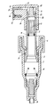
- the pump comprises a cup-shaped body 1 into which there extends, in a manner able to undergo translational movement, a hollow stem 2 from the lower end (relative to the figure) of which there projects a piston 3 which is slidable in a sealed manner against the inner cylindrical wall of the cup-shaped body.
- the stem 2 is urged upwards by a spring 4 acting against longitudinal ribs or fins 5 (the length of which determines the pump capacity) projecting into the cavity within the stem, the lower end of which is freely open.
- the stem is retained by a ring cap 6 which is mounted and snap-locked on the mouth of the cup-shaped body.
- a feed hole intercepted by a suction valve consisting of a plug 7 with a flexible endless seal lip.
- a dip tube 8 which extends (in conventional manner) into a bottle or the like containing the fluid to be delivered after applying the pump.
- a head 9 On the free end of the stem 2 (that facing upwards on the drawing) there is mounted a head 9 provided with an internal cavity 10 which, via channels 11, communicates with a turbulence chamber 12 defined by a shaped insert 13 housed in a seat provided in said head, in the insert there being provided a discharge hole connecting the chamber 12 to the outside.
- the top of the stem 2 is shaped to form a discharge valve consisting of a flexible endless lip 15 which bears and seals (when in the rest state) against the opposing wall of the cavity 10 in the head 9.
- the pump is mounted (and retained in position by any known system, for example by a ring nut or a bush) on the mouth of a bottle containing a liquid into which the dip tube 8 dips.
- the head 9 is now lowered (relative to the finger) against the action of the spring 4, hence pressurizing the liquid until it deforms the lip 15, which withdraws from the opposing surface of the cavity 10 so that the pressurized liquid passes through the cavity 10, the channels 11 and the turbulence chamber 12, to be expelled to the outside in finely atomized form through the discharge hole 14.
- the liquid present in the cup-shaped body cannot flow back into the bottle, this being prevented by the plug 7.
Landscapes
- Jet Pumps And Other Pumps (AREA)
- Reciprocating Pumps (AREA)
- Structures Of Non-Positive Displacement Pumps (AREA)
- Closures For Containers (AREA)
Applications Claiming Priority (2)
| Application Number | Priority Date | Filing Date | Title |
|---|---|---|---|
| ITMI941110A IT1269860B (it) | 1994-05-30 | 1994-05-30 | Pompetta a struttura semplificata, per l'erogazione di fluidi sotto pressione |
| ITMI941110 | 1994-05-30 |
Publications (2)
| Publication Number | Publication Date |
|---|---|
| EP0686434A2 true EP0686434A2 (de) | 1995-12-13 |
| EP0686434A3 EP0686434A3 (de) | 1996-06-12 |
Family
ID=11369014
Family Applications (1)
| Application Number | Title | Priority Date | Filing Date |
|---|---|---|---|
| EP95103728A Withdrawn EP0686434A3 (de) | 1994-05-30 | 1995-03-15 | Pumpe zum Verteilen von Flüssigkeiten unter Druck |
Country Status (2)
| Country | Link |
|---|---|
| EP (1) | EP0686434A3 (de) |
| IT (1) | IT1269860B (de) |
Cited By (3)
| Publication number | Priority date | Publication date | Assignee | Title |
|---|---|---|---|---|
| EP0867232A3 (de) * | 1997-03-28 | 1999-04-14 | SAR S.p.A. | Mikropumpe mit einem Dosierventil zur Vernebelung von Fluiden |
| EP0867231A3 (de) * | 1997-03-28 | 1999-04-14 | SAR S.p.A. | Mikropumpe zur Vernebelung von Fluiden |
| DE102010020726A1 (de) * | 2010-05-17 | 2011-11-17 | Inotech Kunststofftechnik Gmbh | Mehrkomponentenförderelement für Spendervorrichtungen |
Citations (2)
| Publication number | Priority date | Publication date | Assignee | Title |
|---|---|---|---|---|
| US4046495A (en) * | 1976-09-30 | 1977-09-06 | Grimm Jr Bruce F | Dispenser pump |
| WO1985005572A1 (en) * | 1984-06-01 | 1985-12-19 | Bundschuh Robert L | Pump dispenser with slidable trigger |
-
1994
- 1994-05-30 IT ITMI941110A patent/IT1269860B/it active IP Right Grant
-
1995
- 1995-03-15 EP EP95103728A patent/EP0686434A3/de not_active Withdrawn
Patent Citations (2)
| Publication number | Priority date | Publication date | Assignee | Title |
|---|---|---|---|---|
| US4046495A (en) * | 1976-09-30 | 1977-09-06 | Grimm Jr Bruce F | Dispenser pump |
| WO1985005572A1 (en) * | 1984-06-01 | 1985-12-19 | Bundschuh Robert L | Pump dispenser with slidable trigger |
Cited By (6)
| Publication number | Priority date | Publication date | Assignee | Title |
|---|---|---|---|---|
| US6016974A (en) * | 1997-03-27 | 2000-01-25 | Sar S.P.A. | Micropump for the nebulization of fluids with enhanced metering valve |
| EP0867232A3 (de) * | 1997-03-28 | 1999-04-14 | SAR S.p.A. | Mikropumpe mit einem Dosierventil zur Vernebelung von Fluiden |
| EP0867231A3 (de) * | 1997-03-28 | 1999-04-14 | SAR S.p.A. | Mikropumpe zur Vernebelung von Fluiden |
| US6003737A (en) * | 1997-03-28 | 1999-12-21 | Sar S.P.A. | Enhanced micropump for the nebulization of fluids |
| DE102010020726A1 (de) * | 2010-05-17 | 2011-11-17 | Inotech Kunststofftechnik Gmbh | Mehrkomponentenförderelement für Spendervorrichtungen |
| DE102010020726B4 (de) * | 2010-05-17 | 2016-11-24 | Inotech Kunststofftechnik Gmbh | Mehrkomponentenförderelement für Spendervorrichtungen |
Also Published As
| Publication number | Publication date |
|---|---|
| IT1269860B (it) | 1997-04-15 |
| EP0686434A3 (de) | 1996-06-12 |
| ITMI941110A1 (it) | 1995-11-30 |
| ITMI941110A0 (it) | 1994-05-30 |
Similar Documents
| Publication | Publication Date | Title |
|---|---|---|
| US4830284A (en) | Atomizing or dosing pump | |
| US4230242A (en) | Triple seal valve member for an atomizing pump dispenser | |
| EP0721803B1 (de) | Pumpe zur Abgabe von verteilten Flüssigkeiten | |
| US4735347A (en) | Single puff atomizing pump dispenser | |
| EP0301615B1 (de) | Ausgabepumpe, die in einen Flüssigkeitsbehälter eingesetzt werden kann | |
| US6974055B2 (en) | Adapter for a manually operated dispensing device of containers of liquid | |
| US4503996A (en) | Liquid atomizer having a double-acting pump | |
| US4325501A (en) | Extended spray pump | |
| US4669664A (en) | Hand manipulatable sprayer | |
| CA1299536C (en) | Water jet injection device for use with dispensers for producing and dispensing beverages mixed of fruit syrup or concentrate and water | |
| US20110240677A1 (en) | Airless double-piston double-action pump and cosmetics bottle dispensing device | |
| US3514017A (en) | Pressure regulating structure for piston pump | |
| EP0869554A3 (de) | Spenderpumpe zur Verkapselung von integrierten Schaltungen | |
| US5850948A (en) | Finger-operable pump with piston biasing post | |
| EP0536617A1 (de) | Handbetätigbare Pumpe zur Ausgabe von flüssigen oder pastösen Produkten bei einem voreingestellten konstanten Druck | |
| AU709898B2 (en) | Liquid dispenser with trigger sprayer | |
| US4503997A (en) | Dispensing pump adapted for pressure filling | |
| US4527594A (en) | Check valve | |
| EP0484615A1 (de) | Handbetätigte Pumpe für Fluide | |
| US4325500A (en) | Extended spray pump | |
| US4325499A (en) | Extended spray pump | |
| US4215804A (en) | Manual control dispensing pump for liquid containers | |
| EP0686434A2 (de) | Pumpe zum Verteilen von Flüssigkeiten unter Druck | |
| US6942125B2 (en) | Manually operable invertible pump for dispensing atomized liquids | |
| US4450938A (en) | Air line lubricator |
Legal Events
| Date | Code | Title | Description |
|---|---|---|---|
| PUAI | Public reference made under article 153(3) epc to a published international application that has entered the european phase |
Free format text: ORIGINAL CODE: 0009012 |
|
| AK | Designated contracting states |
Kind code of ref document: A2 Designated state(s): AT BE CH DE DK ES FR GB IT LI NL SE |
|
| PUAL | Search report despatched |
Free format text: ORIGINAL CODE: 0009013 |
|
| AK | Designated contracting states |
Kind code of ref document: A3 Designated state(s): AT BE CH DE DK ES FR GB IT LI NL SE |
|
| 17P | Request for examination filed |
Effective date: 19961212 |
|
| STAA | Information on the status of an ep patent application or granted ep patent |
Free format text: STATUS: THE APPLICATION HAS BEEN WITHDRAWN |
|
| 18W | Application withdrawn |
Withdrawal date: 19960702 |