EP0686429A1 - Elektrostatischer Abscheider - Google Patents
Elektrostatischer Abscheider Download PDFInfo
- Publication number
- EP0686429A1 EP0686429A1 EP95108763A EP95108763A EP0686429A1 EP 0686429 A1 EP0686429 A1 EP 0686429A1 EP 95108763 A EP95108763 A EP 95108763A EP 95108763 A EP95108763 A EP 95108763A EP 0686429 A1 EP0686429 A1 EP 0686429A1
- Authority
- EP
- European Patent Office
- Prior art keywords
- dust
- electrostatic precipitator
- collecting
- discharge
- electrodes
- Prior art date
- Legal status (The legal status is an assumption and is not a legal conclusion. Google has not performed a legal analysis and makes no representation as to the accuracy of the status listed.)
- Granted
Links
Images


Classifications
-
- B—PERFORMING OPERATIONS; TRANSPORTING
- B03—SEPARATION OF SOLID MATERIALS USING LIQUIDS OR USING PNEUMATIC TABLES OR JIGS; MAGNETIC OR ELECTROSTATIC SEPARATION OF SOLID MATERIALS FROM SOLID MATERIALS OR FLUIDS; SEPARATION BY HIGH-VOLTAGE ELECTRIC FIELDS
- B03C—MAGNETIC OR ELECTROSTATIC SEPARATION OF SOLID MATERIALS FROM SOLID MATERIALS OR FLUIDS; SEPARATION BY HIGH-VOLTAGE ELECTRIC FIELDS
- B03C3/00—Separating dispersed particles from gases or vapour, e.g. air, by electrostatic effect
- B03C3/34—Constructional details or accessories or operation thereof
- B03C3/40—Electrode constructions
- B03C3/45—Collecting-electrodes
-
- B—PERFORMING OPERATIONS; TRANSPORTING
- B03—SEPARATION OF SOLID MATERIALS USING LIQUIDS OR USING PNEUMATIC TABLES OR JIGS; MAGNETIC OR ELECTROSTATIC SEPARATION OF SOLID MATERIALS FROM SOLID MATERIALS OR FLUIDS; SEPARATION BY HIGH-VOLTAGE ELECTRIC FIELDS
- B03C—MAGNETIC OR ELECTROSTATIC SEPARATION OF SOLID MATERIALS FROM SOLID MATERIALS OR FLUIDS; SEPARATION BY HIGH-VOLTAGE ELECTRIC FIELDS
- B03C3/00—Separating dispersed particles from gases or vapour, e.g. air, by electrostatic effect
- B03C3/02—Plant or installations having external electricity supply
- B03C3/04—Plant or installations having external electricity supply dry type
- B03C3/08—Plant or installations having external electricity supply dry type characterised by presence of stationary flat electrodes arranged with their flat surfaces parallel to the gas stream
-
- B—PERFORMING OPERATIONS; TRANSPORTING
- B03—SEPARATION OF SOLID MATERIALS USING LIQUIDS OR USING PNEUMATIC TABLES OR JIGS; MAGNETIC OR ELECTROSTATIC SEPARATION OF SOLID MATERIALS FROM SOLID MATERIALS OR FLUIDS; SEPARATION BY HIGH-VOLTAGE ELECTRIC FIELDS
- B03C—MAGNETIC OR ELECTROSTATIC SEPARATION OF SOLID MATERIALS FROM SOLID MATERIALS OR FLUIDS; SEPARATION BY HIGH-VOLTAGE ELECTRIC FIELDS
- B03C3/00—Separating dispersed particles from gases or vapour, e.g. air, by electrostatic effect
- B03C3/34—Constructional details or accessories or operation thereof
- B03C3/40—Electrode constructions
Definitions
- the present invention relates to an electrostatic precipitator to be used in a power plant, a cement plant, an industrial waste incinerator, a road or a tunnel for removing floating particles or radioactive dust, or for cleaning indoor air.
- An electrostatic precipitator ionizes (charges) fine particle such as dust floating in a gas by applying a high voltage to the gas (or by a corona discharge). The charged particles may then be collected on dust-collecting electrodes of the electrostatic precipitators, by making use of an electric field, to remove the particles (hereinafter referred to as "dust") from the gas.
- An electrostatic precipitator can collect the particles of most kinds of solids and liquid highly efficiently.
- the maintenance and running of the electrostatic precipitator is relatively inexpensive because it has a simple construction and few moving parts.
- the electrostatic precipitator has drawbacks in that its entire structure is large-sized due to the large space where dust is collected, and its construction cost may be raised by expensive parts such as a DC high voltage supply or a high voltage insulator.
- its dust collecting performance is determined by the electric resistivity of the dust. (Reference should be made to pp. 1119 to 1121 of Handbook of Electric Engineering, edited by Association of Electricity and issued by OHM Co., Ltd. on July 10, 1983).
- the present inventor has already introduced small-sized electrostatic precipitators having a high dust collecting efficiency in the inventions described in Japanese Patent Application No. Hei 6-51312 and Japanese Patent Application No. Hei 6-132548. The features of those apparatus will be briefly described below.
- the electrostatic precipitator shown in Fig. 7, includes rectangular plate shaped metal discharge electrodes 101 formed with a series of saw-toothed portions having tips 101a on the edges thereof; and dust-collecting electrodes 102 formed with a number of pores 102a in their faces.
- the dust-collecting electrodes 102 are arranged so that their faces are parallel, and the dust-collecting electrodes 102 are connected through spacers 103 (103a, 103b and 103c) to form dust-collecting electrode groups 104.
- the discharge electrodes 101 are also arranged so that thier faces are parallel, and they are connected through spacers 105 (105a and 105b) to form discharge electrode groups 106.
- These dust-collecting electrode groups 104 and discharge electrode groups 106 are fixed to a frame (not shown) by means of screws 107 extending from the spacers 103 and 105.
- a gas carrying dust particles is introduced in the direction of the arrow into the apparatus.
- This apparatus features pores 102a in the dust-collecting electrodes 102 that cause a current A from the discharge electrodes 101 to be centralized at portions other than the pores 102a on the dust-collecting electrodes 102, as indicated by the arrows in Fig. 8. This increases the current density at the solid portions of the dust-collecting electrodes 102. As a result, a high dust-collecting efficiency is achieved.
- an air flow is established through the pores 102a of the dust-collecting electrodes 102, as shown by the arrows in Fig. 9. Dust particles collected on the electrode are rubbed off by the air flow, which prevents deterioration of the dust collecting ability of the apparatus due to dust built-up.
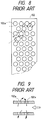
- the electrostatic precipitator shown in Fig. 10 is modified such that the dust-collecting electrodes 102 of Fig. 7 are replaced by steel pipes 108. These pipes 108 are supported by steel beams 109, which may be positioned at the upper, lower or intermediate portions of the pipes 108, if necessary.
- the pipes 108, acting as the dust-collecting electrodes have curved faces which causes collected dust particles to drop by their own weight before dust becomes highly deposited.
- the dust-collecting electrodes have their surfaces covered with the dust for only short time periods, and the dust collecting efficiency of the apparatus is enhanced.
- the electrostatic precipitator shown in Fig. 7 is assembled using numerous spacers, the high number of parts seriously increases the number of steps required for assembly.
- the dust-collecting electrodes have to be manufactured into the desired shape before being attached, their manufacturing steps are troublesome.
- the steel beams 109 have to be prepared because they are used to support the pipes 108.
- the present invention has been conceived in view of the problems thus far described. It is an object of the present invention to provide an electrostatic precipitator which has a high dust collecting efficiency, which is easily manufactured, and which is easily assembled.
- an electrostatic precipitator includes a dust-collecting electrode group and a discharge electrode group, the dust-collecting electrode group being arranged at an upstream side of the electrostatic precipitator.
- the discharge electrode group includes a plurality of rectangular plate shaped metal discharge electrodes having opposite vertical edges punched into semicircles to form a series of saw-toothed portions.
- the dust-collecting electrode group includes a plurality of dust-collecting electrodes, each made of a chain suspended to confront the discharge electrode group at a predetermined spacing. The chains are allowed to rock back and forth with respect to the dicharge electrode group.
- a plurality of discharge electrode groups or dust-collecting electrode groups may be provided.
- a high voltage is applied between the discharge electrodes and the dust-collecting electrodes so that an electric current is established by the corona discharge.
- a gas carrying dust particles is introduced into the portion of the apparatus having the dust-collecting electrode group and the discharge electrode group, the dust in the gas is charged and attracted by the dust-collecting electrodes.
- the dust-collecting electrodes are comprised of chains, these chains have a complicated three-dimensional shape that makes the spacing between the discharge electrodes and the dust-collecting electrodes prominently different, depending upon the location, so that a non-uniform electric field is established.
- the chains are stereoscopic and have faces that project in various directions, they are liable to receive a discharge current from several discharge electrodes such that the current densities on the individual faces forming the chains are enhanced as a whole. As a result, the chains acquire complicated high current intensities along their surface shapes. Moreover, because the chains are suspended in a rocking manner, the positions of the links with respect to one another can freely change.
- a plurality of the dust-collecting electrode groups and discharge electrode groups may be provided along the gas flow direction so that adjoining electrodes exert influences upon each other, thus enhancing the dust-collecting ability of the apparatus.
- Fig. 1 shows the discharge electrode groups A and the dust-collecting electrode groups B of a portion of an entire electrostatic precipitator.
- the discharge electrode groups A are comprised of discharge electrodes 1 which are formed by punching semicircles in the two longer edges of rectangular metal plates to form a series of saw-toothed portions having pointed tips 1a.
- the dust-collecting electrode groups B are comprised of dust-collecting electrodes 10, each of which is formed of a chain comprised of a plurality of links (made of a steel rod having a diameter of 6 to 8 mm). The chains are suspended adjacent one another in a line parallel to the discharge electrode group.
- the discharge electrode groups A and the dust-collecting electrode groups B are paired so that they are provided in a plurality of pairs, as necessary.
- the discharge electrodes of a discharge electrode group A are supported by the spacers 3 (3a).
- the individual dust-collecting electrodes 10 of a dust-collecting electrode group B are suspended by hooks (not shown) disposed on a support frame so that they hang vertically downward. As a result, the dust-collecting electrodes 10 can be freely turned and rocked.
- the chains comprising the dust-collecting electrodes 10 are prepared merely by cutting commercially available chains to a desired length and need not be subjected to any special treatment prior to their attachment. If necessary, moreover, the dust-collecting electrodes 10 may also have their lower ends fixed. It should be noted that the individual links 10a are not prevented from relative movement at their nodes (connected portions of the links) by fixing the upper and lower ends of the chains to a support frame.
- An electrostatic precipitator having discharge electrodes 1 with the aforementioned tips 1a of the saw-toothed portions, and dust-collecting electrodes 10 made of the chains, allows the corona voltage to be approximately 7KV. This is much smaller than the voltage used in prior art electrostatic precipitator, typically 15 KV, and allows for a greater current. Moreover, the semicircular portions on the edges of the discharge electrodes 1 between the tips 1a can act to repel the charged dust against the gas flow.
- the discharge electrodes 1 are disposed such that the spacing a of the dust-collecting electrodes 10 is about two times (or a standard value) as large as the gap b of the immediately downstream discharge electrodes.
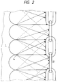
- Fig. 2 is a sectional view taken along lines 2-2 of Fig. 1.
- the current intensities from the saw-toothed tips 1a of the individual discharge electrodes 1 to the surfaces of the dust-collecting electrodes 10 are schematically illustrated by different kinds of arrows. Specifically, thick-line arrows indicate high currents; thin-line arrows indicate low currents; and dotted-line arrows indicate still lower currents.
- FIG. 3 a sectional view showing a portion, as taken along the sectional line 3-3 of Fig. 1, is shown in Fig. 3.
- the thick, thin and broken-line arrows appearing in Fig. 3 indicate the intensities of the currents as in Fig. 2.
- the dust in the gas is charged as it passes between the first discharge electrode group and the first dust-collecting electrode group.
- the charged dust is then collected by the dust-collecting electrodes 10.
- the dust is collected, as shown in Fig. 5, substantially uniformly from the top to the bottom of the dust-collecting electrodes 10 along their surface shapes.
- the dust is deposited such that the dust fills the insdie of the links 10a of the chains.
- the links 10a comprising the chains are allowed to individually rock (receiprocate) so that they are easily turned by the gas flowing through the apparatus. As a result, there is no back or leeward face of the dust-collecting electrodes 10, and dust is deposited on all sides of the chains.
- the dust-collecting electrodes 10 Because of the establishment of the aforementioned current density and fact that the dust-collecting electrodes 10 have complicated three-dimensional shape, the dust is not thickly deposited, even if it is collected. In addition, because the links 10a of the chains are allowed to freely rock so that the links shift their positional relations, the deposited dust is forced to fall off of the surfaces of the chains. In addition, the drop of the collected dust from the dust-collecting electrodes 10 is caused not only by the rocking motions of the chains, but also by the shock of the spark discharge from the discharge electrodes 1 to the dust-collecting electrodes 10. As a result, no substantial operation is required for scraping (dropping) the dust through the use of a hammering means.
- the present invention has the advantages described below. Because the chains used as dust-collecting electrodes may be commercially available ones that do not require any additional modification for use, the cost and time required to manufacture the electrostatic precipitator can be drastically reduced.
- an electrostatic precipitator of the present invention has its electrode weight reduced to 30 to 40 % of the weight of conventional electrodes, which use plate-shaped dust-collecting electrodes.
- the chains have a complicated three-dimensional shape, the spacing between the discharge electrodes and the dust-collecting electrodes varies from place to place along the electrodes such that a non-uniform electric field can be easily established.
- the current density may be increased as a result of the current concentration.
- the chains are stereoscopic and have the variously directed faces, they are susceptible to discharge current from more than one discharge electrode, and the current density in the individual faces composing the chains is increased as a whole. As a result, the chains have a complicated high current intensity along their surface shapes. As a result of all these factors, the electrostatic precipitator has a high dust collecting capacity.
- the links comprising the chains can freely change their positional relations and are vibrated by the pressure of the gas to be treated, such that the deposited dust is easily dropped by the vibration.
- the high dust collecting capacity can be maintained for a long period of time without any dust removing operation using hammering or the like.
- adjoining electrodes exert influences upon each other to enhance the dust collecting capacity of the electrostatic precipitator so that the electrostatic precipitator can be small-sized.
Landscapes
- Electrostatic Separation (AREA)
Applications Claiming Priority (3)
| Application Number | Priority Date | Filing Date | Title |
|---|---|---|---|
| JP14867094 | 1994-06-07 | ||
| JP148670/94 | 1994-06-07 | ||
| JP6148670A JPH07328475A (ja) | 1994-06-07 | 1994-06-07 | 電気集塵装置 |
Publications (2)
| Publication Number | Publication Date |
|---|---|
| EP0686429A1 true EP0686429A1 (de) | 1995-12-13 |
| EP0686429B1 EP0686429B1 (de) | 1999-09-22 |
Family
ID=15457999
Family Applications (1)
| Application Number | Title | Priority Date | Filing Date |
|---|---|---|---|
| EP95108763A Expired - Lifetime EP0686429B1 (de) | 1994-06-07 | 1995-06-07 | Elektrostatischer Abscheider |
Country Status (7)
| Country | Link |
|---|---|
| US (1) | US5603752A (de) |
| EP (1) | EP0686429B1 (de) |
| JP (1) | JPH07328475A (de) |
| CZ (1) | CZ287856B6 (de) |
| DE (1) | DE69512315T2 (de) |
| ES (1) | ES2140580T3 (de) |
| SK (1) | SK281451B6 (de) |
Families Citing this family (43)
| Publication number | Priority date | Publication date | Assignee | Title |
|---|---|---|---|---|
| US20020122751A1 (en) * | 1998-11-05 | 2002-09-05 | Sinaiko Robert J. | Electro-kinetic air transporter-conditioner devices with a enhanced collector electrode for collecting more particulate matter |
| US20030206837A1 (en) | 1998-11-05 | 2003-11-06 | Taylor Charles E. | Electro-kinetic air transporter and conditioner device with enhanced maintenance features and enhanced anti-microorganism capability |
| US20070009406A1 (en) * | 1998-11-05 | 2007-01-11 | Sharper Image Corporation | Electrostatic air conditioner devices with enhanced collector electrode |
| US7695690B2 (en) | 1998-11-05 | 2010-04-13 | Tessera, Inc. | Air treatment apparatus having multiple downstream electrodes |
| US6350417B1 (en) * | 1998-11-05 | 2002-02-26 | Sharper Image Corporation | Electrode self-cleaning mechanism for electro-kinetic air transporter-conditioner devices |
| US7318856B2 (en) * | 1998-11-05 | 2008-01-15 | Sharper Image Corporation | Air treatment apparatus having an electrode extending along an axis which is substantially perpendicular to an air flow path |
| US20050163669A1 (en) * | 1998-11-05 | 2005-07-28 | Sharper Image Corporation | Air conditioner devices including safety features |
| US20020150520A1 (en) * | 1998-11-05 | 2002-10-17 | Taylor Charles E. | Electro-kinetic air transporter-conditioner devices with enhanced emitter electrode |
| US6176977B1 (en) | 1998-11-05 | 2001-01-23 | Sharper Image Corporation | Electro-kinetic air transporter-conditioner |
| US20050199125A1 (en) * | 2004-02-18 | 2005-09-15 | Sharper Image Corporation | Air transporter and/or conditioner device with features for cleaning emitter electrodes |
| US7220295B2 (en) * | 2003-05-14 | 2007-05-22 | Sharper Image Corporation | Electrode self-cleaning mechanisms with anti-arc guard for electro-kinetic air transporter-conditioner devices |
| US6544485B1 (en) * | 2001-01-29 | 2003-04-08 | Sharper Image Corporation | Electro-kinetic device with enhanced anti-microorganism capability |
| US20050210902A1 (en) * | 2004-02-18 | 2005-09-29 | Sharper Image Corporation | Electro-kinetic air transporter and/or conditioner devices with features for cleaning emitter electrodes |
| US20070148061A1 (en) * | 1998-11-05 | 2007-06-28 | The Sharper Image Corporation | Electro-kinetic air transporter and/or air conditioner with devices with features for cleaning emitter electrodes |
| DE10260590B4 (de) * | 2002-12-23 | 2007-06-14 | Keller Lufttechnik Gmbh & Co. Kg | Abscheidesystem |
| US7405672B2 (en) * | 2003-04-09 | 2008-07-29 | Sharper Image Corp. | Air treatment device having a sensor |
| US20050051420A1 (en) * | 2003-09-05 | 2005-03-10 | Sharper Image Corporation | Electro-kinetic air transporter and conditioner devices with insulated driver electrodes |
| US7517503B2 (en) * | 2004-03-02 | 2009-04-14 | Sharper Image Acquisition Llc | Electro-kinetic air transporter and conditioner devices including pin-ring electrode configurations with driver electrode |
| US7906080B1 (en) | 2003-09-05 | 2011-03-15 | Sharper Image Acquisition Llc | Air treatment apparatus having a liquid holder and a bipolar ionization device |
| US7724492B2 (en) | 2003-09-05 | 2010-05-25 | Tessera, Inc. | Emitter electrode having a strip shape |
| US7077890B2 (en) * | 2003-09-05 | 2006-07-18 | Sharper Image Corporation | Electrostatic precipitators with insulated driver electrodes |
| US20050095182A1 (en) * | 2003-09-19 | 2005-05-05 | Sharper Image Corporation | Electro-kinetic air transporter-conditioner devices with electrically conductive foam emitter electrode |
| US7767169B2 (en) * | 2003-12-11 | 2010-08-03 | Sharper Image Acquisition Llc | Electro-kinetic air transporter-conditioner system and method to oxidize volatile organic compounds |
| US20050279905A1 (en) * | 2004-02-18 | 2005-12-22 | Sharper Image Corporation | Air movement device with a quick assembly base |
| US20060018812A1 (en) * | 2004-03-02 | 2006-01-26 | Taylor Charles E | Air conditioner devices including pin-ring electrode configurations with driver electrode |
| US7638104B2 (en) * | 2004-03-02 | 2009-12-29 | Sharper Image Acquisition Llc | Air conditioner device including pin-ring electrode configurations with driver electrode |
| US20060016336A1 (en) * | 2004-07-23 | 2006-01-26 | Sharper Image Corporation | Air conditioner device with variable voltage controlled trailing electrodes |
| US20060018810A1 (en) * | 2004-07-23 | 2006-01-26 | Sharper Image Corporation | Air conditioner device with 3/2 configuration and individually removable driver electrodes |
| US20060016333A1 (en) * | 2004-07-23 | 2006-01-26 | Sharper Image Corporation | Air conditioner device with removable driver electrodes |
| US7285155B2 (en) * | 2004-07-23 | 2007-10-23 | Taylor Charles E | Air conditioner device with enhanced ion output production features |
| US7311762B2 (en) * | 2004-07-23 | 2007-12-25 | Sharper Image Corporation | Air conditioner device with a removable driver electrode |
| US20060018804A1 (en) * | 2004-07-23 | 2006-01-26 | Sharper Image Corporation | Enhanced germicidal lamp |
| EP1850965A4 (de) * | 2005-02-18 | 2011-02-23 | Turbosonic Inc | Stabelektrodenausführung |
| US7399340B2 (en) * | 2005-06-08 | 2008-07-15 | Hamon Research—Cottrell, Inc. | Replacement discharge electrode for electrostatic precipitators and method of assembly |
| US7163572B1 (en) * | 2005-09-16 | 2007-01-16 | Foshan Shunde Nasi Industry Co., Ltd. | Air purifier |
| US7833322B2 (en) * | 2006-02-28 | 2010-11-16 | Sharper Image Acquisition Llc | Air treatment apparatus having a voltage control device responsive to current sensing |
| JP2011101861A (ja) * | 2009-11-11 | 2011-05-26 | Hitachi Plant Technologies Ltd | 移動電極型電気集塵装置の電極板連結チェーンおよび移動電極型電気集塵装置 |
| US20120000627A1 (en) * | 2010-06-30 | 2012-01-05 | Tessera, Inc. | Electrostatic precipitator pre-filter for electrohydrodynamic fluid mover |
| JP6089026B2 (ja) | 2011-03-28 | 2017-03-01 | メグテック ターボソニック インコーポレイテッドMegtec Turbosonic Inc. | 湿式電気集塵機用の耐浸食性導電性複合材料集塵電極 |
| US11027289B2 (en) | 2011-12-09 | 2021-06-08 | Durr Systems Inc. | Wet electrostatic precipitator system components |
| CN103537373B (zh) * | 2013-11-13 | 2016-09-14 | 福建龙净环保股份有限公司 | 一种隔离振打清灰电除尘器及其隔离振打时序控制方法 |
| JP7109194B2 (ja) * | 2018-01-15 | 2022-07-29 | 三菱重工パワー環境ソリューション株式会社 | 電気集塵装置 |
| KR102079796B1 (ko) * | 2018-10-04 | 2020-02-20 | 두산중공업 주식회사 | 집진 모듈 및 이를 포함하는 탈황 장치 |
Citations (3)
| Publication number | Priority date | Publication date | Assignee | Title |
|---|---|---|---|---|
| DE429921C (de) * | 1921-03-22 | 1926-06-08 | Metallbank Fa | Vorrichtung zur elektrischen Niederschlagung von Schwebekoerpern aus Gasen |
| DE1078096B (de) * | 1957-07-25 | 1960-03-24 | Beth Ag Maschf | Elektrofilter zum Abscheiden von festen Teilchen aus Gasen |
| DE1275514B (de) * | 1959-09-19 | 1968-08-22 | Omnical Ges Fuer Kessel Und Ap | Niederschlagselektrode fuer Elektrofilter |
Family Cites Families (21)
| Publication number | Priority date | Publication date | Assignee | Title |
|---|---|---|---|---|
| US1356462A (en) * | 1920-10-19 | Apparatus por the electrical precipitation of suspended matter in | ||
| US1329237A (en) * | 1919-01-06 | 1920-01-27 | Howard I Frisbie | Electric precipitator |
| DE372525C (de) * | 1921-08-23 | 1923-03-29 | Siemens Schuckertwerke G M B H | Verfahren und Vorrichtung zur Verbesserung der Abscheidewirkung bei elektrischen Staubniederschlagsanlagen |
| FR614871A (fr) * | 1926-04-21 | 1926-12-24 | Cie Des Mines D Ostricourt | Dispositif de dépoussiérage des fumées |
| US1992974A (en) * | 1931-03-18 | 1935-03-05 | Thompson Engineering Company | Electrostatic precipitator |
| GB496639A (en) * | 1938-06-29 | 1938-12-02 | Siemens Lurgi Cottrell Elektro | Improvements in or relating to apparatus for the electrical precipitation of suspended particles from gases |
| US2737258A (en) * | 1954-01-18 | 1956-03-06 | Koppers Co Inc | Electrical precipitator |
| US2852092A (en) * | 1955-10-17 | 1958-09-16 | Hal F Fruth | Frame for electric precipitators |
| GB995230A (en) * | 1963-05-14 | 1965-06-16 | Metallgesellschaft Ag | Improvements in or relating to electrostatic precipitators |
| DE2118803B2 (de) * | 1971-04-17 | 1980-08-14 | Metallgesellschaft Ag, 6000 Frankfurt | Anordnung zum Versteifen und Distanzieren von vertikalen, profilierten, streifenförmigen Niederschlagselektroden |
| US3958961A (en) * | 1973-02-02 | 1976-05-25 | United States Filter Corporation | Wet electrostatic precipitators |
| JPS524790B2 (de) * | 1974-05-08 | 1977-02-07 | ||
| JPS5251172A (en) * | 1975-10-21 | 1977-04-23 | Mitsubishi Heavy Ind Ltd | Structure for supporting dust-collecting electrodes |
| GB1528548A (en) * | 1976-08-12 | 1978-10-11 | Vni Gor Metal I Tsvet Metal | Electrostatic precipitators for removing dust from gases |
| DE2711858C2 (de) * | 1977-03-18 | 1984-12-13 | Saarbergwerke AG, 6600 Saarbrücken | Elektroabscheider mit Niederschlagselektroden |
| US4375364A (en) * | 1980-08-21 | 1983-03-01 | Research-Cottrell, Inc. | Rigid discharge electrode for electrical precipitators |
| US4722743A (en) * | 1986-07-21 | 1988-02-02 | Combustion Engineering, Inc. | Collecting electrode panel assembly |
| JP3211032B2 (ja) * | 1991-08-02 | 2001-09-25 | 株式会社エルデック | 電気集塵装置 |
| US5210678A (en) * | 1991-12-16 | 1993-05-11 | Industrial Technology Research Institute | Chain-type discharge wire for use in an electrostatic precipitator |
| JPH0651312A (ja) * | 1992-07-31 | 1994-02-25 | Sanyo Electric Co Ltd | 高輝度平面光源 |
| JPH06132548A (ja) * | 1992-10-16 | 1994-05-13 | Fujitsu Ltd | 半導体受光装置 |
-
1994
- 1994-06-07 JP JP6148670A patent/JPH07328475A/ja active Pending
-
1995
- 1995-05-29 SK SK714-95A patent/SK281451B6/sk unknown
- 1995-05-31 US US08/455,033 patent/US5603752A/en not_active Expired - Fee Related
- 1995-06-06 CZ CZ19951444A patent/CZ287856B6/cs not_active IP Right Cessation
- 1995-06-07 ES ES95108763T patent/ES2140580T3/es not_active Expired - Lifetime
- 1995-06-07 DE DE69512315T patent/DE69512315T2/de not_active Expired - Fee Related
- 1995-06-07 EP EP95108763A patent/EP0686429B1/de not_active Expired - Lifetime
Patent Citations (3)
| Publication number | Priority date | Publication date | Assignee | Title |
|---|---|---|---|---|
| DE429921C (de) * | 1921-03-22 | 1926-06-08 | Metallbank Fa | Vorrichtung zur elektrischen Niederschlagung von Schwebekoerpern aus Gasen |
| DE1078096B (de) * | 1957-07-25 | 1960-03-24 | Beth Ag Maschf | Elektrofilter zum Abscheiden von festen Teilchen aus Gasen |
| DE1275514B (de) * | 1959-09-19 | 1968-08-22 | Omnical Ges Fuer Kessel Und Ap | Niederschlagselektrode fuer Elektrofilter |
Also Published As
| Publication number | Publication date |
|---|---|
| DE69512315D1 (de) | 1999-10-28 |
| DE69512315T2 (de) | 2000-02-03 |
| CZ144495A3 (en) | 1996-04-17 |
| CZ287856B6 (en) | 2001-02-14 |
| JPH07328475A (ja) | 1995-12-19 |
| SK71495A3 (en) | 1997-08-06 |
| ES2140580T3 (es) | 2000-03-01 |
| US5603752A (en) | 1997-02-18 |
| SK281451B6 (sk) | 2001-03-12 |
| EP0686429B1 (de) | 1999-09-22 |
Similar Documents
| Publication | Publication Date | Title |
|---|---|---|
| EP0686429B1 (de) | Elektrostatischer Abscheider | |
| RU2143327C1 (ru) | Электростатический осадитель | |
| US4126434A (en) | Electrostatic dust precipitators | |
| US4725289A (en) | High conversion electrostatic precipitator | |
| US5254155A (en) | Wet electrostatic ionizing element and cooperating honeycomb passage ways | |
| US4412850A (en) | Electric dust collector | |
| CA1159773A (en) | Wet electrostatic precipitator having removable nested hexagonal collector plates and magnetic aligning and rapping means | |
| US4521229A (en) | Tubular discharge electrode for electrostatic precipitator | |
| US4381927A (en) | Corona electrode apparatus | |
| US5210678A (en) | Chain-type discharge wire for use in an electrostatic precipitator | |
| EP0833693A1 (de) | Aufhangvorrichtung, kontroll- und klopfmechanismus der sammelelektroden in einem elektrostatischen abscheider | |
| US4326861A (en) | Dust-collecting assembly for electrostatic precipitator | |
| US2694464A (en) | Electrical precipitator | |
| US4431434A (en) | Electrostatic precipitator using a temperature controlled electrode collector | |
| US4747856A (en) | Lower end alignment device for electrostatic precipitator collector electrodes | |
| EP0703006A1 (de) | Elektrostatischer Abscheider | |
| US3514923A (en) | Electrostatic prfcipitators | |
| RU2151009C1 (ru) | Электрофильтр | |
| KR100191785B1 (ko) | 전기식 집진방법과 그 장치 | |
| JPH07313902A (ja) | 電気集塵装置 | |
| RU2216478C1 (ru) | Электрофильтр | |
| JP2000140690A (ja) | 乾式除塵装置 | |
| GB1562844A (en) | Electrostatic dust precipitators | |
| CN117548231A (zh) | 一种设有导电滤板的顶部电磁锤振打电除尘器 | |
| KR790001998B1 (ko) | 정전식 집진장치 |
Legal Events
| Date | Code | Title | Description |
|---|---|---|---|
| PUAI | Public reference made under article 153(3) epc to a published international application that has entered the european phase |
Free format text: ORIGINAL CODE: 0009012 |
|
| AK | Designated contracting states |
Kind code of ref document: A1 Designated state(s): CH DE ES FR GB IT LI SE |
|
| 17P | Request for examination filed |
Effective date: 19960523 |
|
| RAP1 | Party data changed (applicant data changed or rights of an application transferred) |
Owner name: ERDEC CO., LTD. |
|
| 17Q | First examination report despatched |
Effective date: 19980707 |
|
| GRAG | Despatch of communication of intention to grant |
Free format text: ORIGINAL CODE: EPIDOS AGRA |
|
| GRAG | Despatch of communication of intention to grant |
Free format text: ORIGINAL CODE: EPIDOS AGRA |
|
| GRAH | Despatch of communication of intention to grant a patent |
Free format text: ORIGINAL CODE: EPIDOS IGRA |
|
| GRAH | Despatch of communication of intention to grant a patent |
Free format text: ORIGINAL CODE: EPIDOS IGRA |
|
| GRAA | (expected) grant |
Free format text: ORIGINAL CODE: 0009210 |
|
| STAA | Information on the status of an ep patent application or granted ep patent |
Free format text: STATUS: THE PATENT HAS BEEN GRANTED |
|
| AK | Designated contracting states |
Kind code of ref document: B1 Designated state(s): CH DE ES FR GB IT LI SE |
|
| REG | Reference to a national code |
Ref country code: CH Ref legal event code: EP |
|
| REF | Corresponds to: |
Ref document number: 69512315 Country of ref document: DE Date of ref document: 19991028 |
|
| ET | Fr: translation filed | ||
| REG | Reference to a national code |
Ref country code: CH Ref legal event code: NV Representative=s name: BUECHEL & PARTNER AG PATENTBUERO |
|
| REG | Reference to a national code |
Ref country code: ES Ref legal event code: FG2A Ref document number: 2140580 Country of ref document: ES Kind code of ref document: T3 |
|
| PLBE | No opposition filed within time limit |
Free format text: ORIGINAL CODE: 0009261 |
|
| 26N | No opposition filed | ||
| REG | Reference to a national code |
Ref country code: GB Ref legal event code: IF02 |
|
| PGFP | Annual fee paid to national office [announced via postgrant information from national office to epo] |
Ref country code: CH Payment date: 20070608 Year of fee payment: 13 |
|
| PGFP | Annual fee paid to national office [announced via postgrant information from national office to epo] |
Ref country code: ES Payment date: 20070615 Year of fee payment: 13 |
|
| PGFP | Annual fee paid to national office [announced via postgrant information from national office to epo] |
Ref country code: SE Payment date: 20070619 Year of fee payment: 13 |
|
| PGFP | Annual fee paid to national office [announced via postgrant information from national office to epo] |
Ref country code: DE Payment date: 20070626 Year of fee payment: 13 |
|
| PGFP | Annual fee paid to national office [announced via postgrant information from national office to epo] |
Ref country code: GB Payment date: 20070612 Year of fee payment: 13 |
|
| PGFP | Annual fee paid to national office [announced via postgrant information from national office to epo] |
Ref country code: IT Payment date: 20070629 Year of fee payment: 13 |
|
| PGFP | Annual fee paid to national office [announced via postgrant information from national office to epo] |
Ref country code: FR Payment date: 20070621 Year of fee payment: 13 |
|
| REG | Reference to a national code |
Ref country code: CH Ref legal event code: PL |
|
| EUG | Se: european patent has lapsed | ||
| GBPC | Gb: european patent ceased through non-payment of renewal fee |
Effective date: 20080607 |
|
| REG | Reference to a national code |
Ref country code: FR Ref legal event code: ST Effective date: 20090228 |
|
| PG25 | Lapsed in a contracting state [announced via postgrant information from national office to epo] |
Ref country code: DE Free format text: LAPSE BECAUSE OF NON-PAYMENT OF DUE FEES Effective date: 20090101 |
|
| PG25 | Lapsed in a contracting state [announced via postgrant information from national office to epo] |
Ref country code: LI Free format text: LAPSE BECAUSE OF NON-PAYMENT OF DUE FEES Effective date: 20080630 Ref country code: GB Free format text: LAPSE BECAUSE OF NON-PAYMENT OF DUE FEES Effective date: 20080607 Ref country code: CH Free format text: LAPSE BECAUSE OF NON-PAYMENT OF DUE FEES Effective date: 20080630 |
|
| REG | Reference to a national code |
Ref country code: ES Ref legal event code: FD2A Effective date: 20080609 |
|
| PG25 | Lapsed in a contracting state [announced via postgrant information from national office to epo] |
Ref country code: IT Free format text: LAPSE BECAUSE OF NON-PAYMENT OF DUE FEES Effective date: 20080607 Ref country code: FR Free format text: LAPSE BECAUSE OF NON-PAYMENT OF DUE FEES Effective date: 20080630 |
|
| PG25 | Lapsed in a contracting state [announced via postgrant information from national office to epo] |
Ref country code: ES Free format text: LAPSE BECAUSE OF NON-PAYMENT OF DUE FEES Effective date: 20080609 |
|
| PG25 | Lapsed in a contracting state [announced via postgrant information from national office to epo] |
Ref country code: SE Free format text: LAPSE BECAUSE OF NON-PAYMENT OF DUE FEES Effective date: 20080608 |