EP0686293B1 - Münzverarbeitungsvorrichtung und verfahren zum bestimmen von daten bezüglich sich bewegender münzen - Google Patents
Münzverarbeitungsvorrichtung und verfahren zum bestimmen von daten bezüglich sich bewegender münzen Download PDFInfo
- Publication number
- EP0686293B1 EP0686293B1 EP94907637A EP94907637A EP0686293B1 EP 0686293 B1 EP0686293 B1 EP 0686293B1 EP 94907637 A EP94907637 A EP 94907637A EP 94907637 A EP94907637 A EP 94907637A EP 0686293 B1 EP0686293 B1 EP 0686293B1
- Authority
- EP
- European Patent Office
- Prior art keywords
- coin
- output
- response
- sensor
- route
- Prior art date
- Legal status (The legal status is an assumption and is not a legal conclusion. Google has not performed a legal analysis and makes no representation as to the accuracy of the status listed.)
- Expired - Lifetime
Links
- 238000000034 method Methods 0.000 title claims description 36
- 230000002401 inhibitory effect Effects 0.000 claims description 4
- 238000010606 normalization Methods 0.000 description 5
- 238000012545 processing Methods 0.000 description 4
- 238000012360 testing method Methods 0.000 description 4
- 238000001514 detection method Methods 0.000 description 2
- 238000010586 diagram Methods 0.000 description 1
- 238000011156 evaluation Methods 0.000 description 1
- 238000000605 extraction Methods 0.000 description 1
- 230000001939 inductive effect Effects 0.000 description 1
- 238000003780 insertion Methods 0.000 description 1
- 230000037431 insertion Effects 0.000 description 1
- 239000000463 material Substances 0.000 description 1
- 239000002184 metal Substances 0.000 description 1
- 230000003287 optical effect Effects 0.000 description 1
- 230000000717 retained effect Effects 0.000 description 1
- 230000001960 triggered effect Effects 0.000 description 1
Images
Classifications
-
- G—PHYSICS
- G07—CHECKING-DEVICES
- G07F—COIN-FREED OR LIKE APPARATUS
- G07F1/00—Coin inlet arrangements; Coins specially adapted to operate coin-freed mechanisms
- G07F1/04—Coin chutes
- G07F1/041—Coin chutes with means, other than for testing currency, for dealing with inserted foreign matter, e.g. "stuffing", "stringing" or "salting"
- G07F1/042—Coin chutes with means, other than for testing currency, for dealing with inserted foreign matter, e.g. "stuffing", "stringing" or "salting" the foreign matter being a long flexible member attached to a coin
- G07F1/044—Automatic detection of the flexible member
-
- G—PHYSICS
- G01—MEASURING; TESTING
- G01V—GEOPHYSICS; GRAVITATIONAL MEASUREMENTS; DETECTING MASSES OR OBJECTS; TAGS
- G01V1/00—Seismology; Seismic or acoustic prospecting or detecting
- G01V1/001—Acoustic presence detection
-
- G—PHYSICS
- G07—CHECKING-DEVICES
- G07D—HANDLING OF COINS OR VALUABLE PAPERS, e.g. TESTING, SORTING BY DENOMINATIONS, COUNTING, DISPENSING, CHANGING OR DEPOSITING
- G07D5/00—Testing specially adapted to determine the identity or genuineness of coins, e.g. for segregating coins which are unacceptable or alien to a currency
-
- G—PHYSICS
- G07—CHECKING-DEVICES
- G07F—COIN-FREED OR LIKE APPARATUS
- G07F1/00—Coin inlet arrangements; Coins specially adapted to operate coin-freed mechanisms
- G07F1/04—Coin chutes
- G07F1/048—Coin chutes with means for damping coin motion
Definitions
- This information relates to coin handling apparatus, and is particularly, but not exclusively, concerned with apparatus of the type incorporating a coin validator for determining authenticity of coins, and a coin routing device for directing coins along alternative paths, for example to a reject slot or coin storage location, in dependence upon the output of the coin validator.
- sensors e.g. optical, inductive, or piezoelectric, each of which detects when a coin reaches a particular position within the apparatus. See, e.g. EP-A-0 470 587. Typically, several such sensors are provided. The use of such sensors increases the cost of the apparatus, and adds to the difficulty of assembly as a result of both the need to position the sensors accurately and the requirement to provide connecting leads.
- EP-A-0 477 731 and US-A-5 092 816 disclose a coin handling apparatus in which an acoustic sensor detects impacts at a number of positions within the apparatus in order to control the timing of various aspects of the operation of the apparatus. In particular, there are two gates which are closed in response to detecting an impact. There is also disclosed a technique for measuring the interval between an impact produced as a coin enters a coin tube and the impact produced when the coin hits the top of the stack of coins stored in the tube, and deducing from this the height of the stack and therefore the number of coins stored in the tube.
- a single sensor e.g. a piezoelectric sensor mounted on a coin handling apparatus can pick up vibrations produced by coin impacts at different positions within the apparatus, and the pattern of the output of the sensor will differ depending upon the route taken by the coin.
- the term "single" is used to indicate that the apparatus has at least one sensor which can detect impacts at at least two different positions; it would be possible to provide one or more additional sensors if desired, or if necessary to detect impacts at further positions.
- this could be achieved by examining just the pattern of the output of the sensor.
- the nature of the impact vibrations e.g. the frequency and/or amplitude response thereof, varies in dependence on the position of impact, the vibration characteristics can be examined also.
- the invention also extends to coin handling apparatus including control means operable to perform the method of the invention.
- a routing means which directs valid coins to a coin storage location, and which as a result of the insertion of such valid coins issues a credit signal enabling the dispensing of products or the performing of services by a machine.
- a known fraud technique in such apparatus involves causing an inserted valid coin to be directed to a reject path where it is returned to the user, instead of to the coin storage location.
- a coin handling apparatus may include a control means which detects the routing of the coin using a method referred to above, and cancels the credit when it is found that the coin has been directed to the reject path.
- the credit signal is often generated in response to the coin passing what is known as the "post-gate sensor", which is located downstream of the accept gate through which pass coins deemed to be valid.
- the routing detection technique described above could be used to trigger the credit signal when a coin is determined to have taken the accept path.
- the post-gate sensor be retained, and for the credit signal to be triggered in response either to the post-gate sensor alone, or to a combination of an output from the post-gate sensor and an indication from the routing-detection arrangement that the coin has taken the accept path.
- the arrangement is preferably such that a signal indicative of a fault or error condition may be generated in dependence upon the route which is indicated by the signal.
- a signal indicative of a fault or error condition may be generated in dependence upon the route which is indicated by the signal.
- the apparatus is arranged to control the routing of a coin so that it is directed to a particular destination, but the signal derived from the sensor indicates that it has taken a different route, an error or fault signal may be provided and appropriate action taken.
- the signal may be provided as an external output signal (e.g. indicative of attempted fraud) and could be used to generate an alarm, switch off the machine, turn on a video camera, etc.
- the arrangement is such that a signal indicative that a particular route has been taken will only be provided if the sensor has detected at least one impact associated with that route.
- the sensor is preferably arranged to be capable of detecting impacts at a plurality of positions each associated with a respective one of the different routes.
- the sensor is preferably also arranged to sense an impact at at least one position which is common to at least a plurality of the routes.
- the sensor is operable to detect the coin reaching at least three discrete positions within the apparatus. Preferably, at least two of these are known positions. A further sensed position may vary depending upon the route taken by the coin. A normalization procedure may be adopted using the response of the sensor to the coin reaching the two known positions for reliably distinguishing between the different signals produced in response to the alternative further positions being reached in dependence upon the different routing of the coin.
- the speed of the coin may be determinable from the sensor output. For example, if a normalization procedure is adopted, the outputs generated by the sensor when the coin reaches the two known positions may give an indication of coin speed, which can then be used to predict the time at which the coin reaches the further position, which may vary depending upon the routing of the coin. Even if normalization is not used, coin speed may still be calculable by detecting the time between the coin reaching two positions which are sensed by the sensor.
- a separate aspect of the invention relates to a method of determining the speed of a coin travelling through a coin handling apparatus, the method comprising examining the output of a sensor responsive to vibrations resulting from impacts of a coin at different positions in the apparatus, and calculating coin speed in accordance with the time between signals within the output representing impacts produced when the coin reaches particular positions.
- the invention also extends to a coin handling apparatus having a control means which evaluates coin speed in this way.
- the evaluation of coin speed may be used for a number of purposes, e.g. for determining when speed has been altered as a result of the coin being attached to a string which is sometimes done in order to defraud a coin validator.
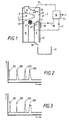
- a coin handling apparatus (2) comprises a coin validator generally indicated at (4) followed by a routing arrangement comprising a gate (6) which can be opened to permit coins leaving the validator to enter an accept path (8), or can be left closed so that coins will be deflected by the gate into a reject path (10).
- the accept path (8) may lead to a coin storage means such as a change tube and/or a cashbox (12).
- the reject path (10) directs coins to the user of the apparatus.
- snubber (14) of known type onto which inserted coins fall.
- the snubber (14) absorbs much of the kinetic energy of the coin.
- the coin then travels along a path (16) past a testing station (18), and then impacts a side wall (20) before dropping towards the gate (6). If the gate (6) is closed, the coin is deflected such that it travels along a path (22), as indicated at (24), and then hits a further side wall (26) before falling into the reject path (10). If the gate is open, the coin falls straight into the accept path (8), and then impacts a deflecting surface (28).
- the various impacts of the coin are sensed by a sensor (30) mounted on a metal channel (32) within which the apparatus (2) is housed.
- the sensor may be a piezoelectric sensor, or other acoustic sensor. It is arranged such that it is sensitive to noise transmitted through the structure of the apparatus, but insensitive to airborne noise.
- a control means (34) is responsive to outputs (36) from the testing station (18) for classifying inserted coins, and to an output (38) from the sensor (30) for determining information regarding movement of coins in the apparatus.
- a post-gate sensor (40) located below the gate (6) detects the presence of a coin and has an output (42) which is also presented to the control means (34). Outputs (44) control the operation of a vending machine or the like.
- the output of the sensor (30) throughout a predetermined period is subjected to processing in order to simplify and smooth the signal waveform, and then to detect the route taken by a coin.
- This predetermined period is initiated upon, or at a predetermined delay after, the occurrence of a particular event.
- This event may be the generation of the signal which opens the gate (6), or a signal generated by a further coin-detecting sensor such as a discrete arrival sensor or a sensor of the station (18).
- Arrival sensing techniques using discrete arrival sensors or coin-testing sensors are well known in the art. It will be understood that if desired, the signal processing of the sensor output may be performed only if a coin is tested and determined to be valid.
- the output of the sensor (30) can be converted into successive data values each indicative of the frequency of the vibration sensed by the sensor.
- Various mathematical algorithms are known for operating on successive data values of this type in order to provide a simplified output.
- the Convex Shape Hull Simplification technique is used. This creates a window over the data whose length is predetermined (e.g. 50 data points). The technique draws a line from the left hand edge of the window to all the data points within the window. It then searches for the steepest of these lines (either positive or negative). When this line is found it is broken up into the same number of data points so that the record remains the same length. The window is then moved to this new point and the process is repeated over the entire length of the record. This technique turns the waveform into a series of straight lines but retains the major features, peaks, etc.
- the Savitzky Golay method is then used to smooth the resulting waveform. This is based on the mean of 'n' data points (e.g. 9) and rounds the data to look similar to the original waveform.
- the resulting waveform may for example look like that shown in Fig. 2, in which the abscissa represents time and the ordinate represents frequency.
- an initial detectable event 100 e.g. a signal from a separate arrival sensor
- the route adopted by the coin can thus be determined by detecting whether a peak 300 appears, or whether a peak 400 appears in the output of the sensor. It will be appreciated that the exact time at which a peak appears may depend upon the velocity of the coin. Therefore, it might be possible for the two peaks 300 and 400 to be confused. To avoid this, preferably there is a normalization step whereby the time between two events (e.g. the event 100 and the peak 200) can be used to determine the expected times at which the peaks 300 and 400 appear so that these times are accurately predictable irrespective of the coin speed.
- the time between two events e.g. the event 100 and the peak 200
- the signals from the sensor can be processed in order to perform the determination of whether a peak 300 or a peak 400 has appeared in the output.
- one possibility would be to perform a feature extraction on the simplified waveform mentioned above, so that the times at which particular peaks occur are determined.
- a standard normalization technique can be applied, and the resulting data can then be passed through a known form of classifier, e.g. a linear discriminant classifier, to judge whether or not the peaks 300 and 400 have appeared.
- the different impacts produced by a coin travelling through the apparatus may generate vibrations of different characteristics, for example some impacts producing briefer, higher-frequency vibrations than others.
- the apparatus can be manufactured to ensure that this occurs, for example by including special-purpose inserts at predetermined positions along the coin path, the inserts being made of materials selected so as to produce distinctive vibrations upon impact by coins.
- Figure 3 shows the output of a sensor (30) in such an arrangement, and it will be noted that the individual peaks have different forms. In such an arrangement, added reliability can be provided by a processing technique whereby individual peaks are recognised only if they occur within an expected interval and only if they have expected characteristics for example in terms of duration, frequency and/or amplitude.
- the peaks could be recognised solely on the basis of their characteristics, rather than on the time at which they occur. This could be achieved for example by performing a Fourier transform on the output of the sensor (30), for example to convert the output to the frequency domain, and then recognising the presence of a peak only if the appropriate characteristics are found to be present in the output.
- the sensor (30) could also be used to test whether the coin is valid.
- the use of piezoelectric sensors for checking coin validity is well known in the art. See for example GB-A-2 236 609.
- the operation of the apparatus is as follows. If a coin has been judged to be valid, the control means (34) can be arranged to generate a credit signal only if a signal is received from the post-gate sensor (40) and no peak 400 is detected, a peak 400 thus inhibiting any credit signal and preventing operation of the vending machine or the like. The presence of a peak 300 may also be required to generate the credit signal. Also, the control means (34) can be arranged to detect the coin speed from the interval between at least two of the peaks, and to cancel credit if the coin is travelling unusually slowly, i.e. if the speed is less than a predetermined value.
Landscapes
- Physics & Mathematics (AREA)
- General Physics & Mathematics (AREA)
- Acoustics & Sound (AREA)
- Life Sciences & Earth Sciences (AREA)
- Engineering & Computer Science (AREA)
- Environmental & Geological Engineering (AREA)
- Geology (AREA)
- Remote Sensing (AREA)
- General Life Sciences & Earth Sciences (AREA)
- Geophysics (AREA)
- Testing Of Coins (AREA)
- Control Of Vending Devices And Auxiliary Devices For Vending Devices (AREA)
Claims (24)
- Verfahren zur Bestimmung des Weges einer durch eine Münzverarbeitungsvorrichtung sich bewegenden Münze (24) aus einer Vielzahl verschiedener möglicher Wege, dadurch gekennzeichnet, daß das Ausgangssignal eines einzelnen, auf Schwingungen ansprechenden Sensors (30) herangezogen wird, die durch Stöße einer Münze an mehrere Stellen der gesamten Vorrichtung verursacht werden, um zwischen einer ersten und einer zweiten Art von Ausgangssignal entsprechend einer Münzbewegung entlang eines ersten bzw. zweiten Weges zu unterscheiden, und daß entweder ein den ersten Weg anzeigendes Signal oder ein den zweiten Weg anzeigendes Signal abhängig von der Art des Ausgangssignals erzeugt wird.
- Verfahren nach Anspruch 1, dadurch gekennzeichnet, daß sowohl die erste als auch die zweite Art von Ausgangssignal auf eine Vielzahl von Stößen hin erzeugt werden.
- Verfahren nach Anspruch 2, dadurch gekennzeichnet, daß für den ersten und den zweiten Weg eine gemeinsame Stelle existiert, wobei sowohl die erste als auch die zweite Art des Ausgangssignals ein einem Stoß an dieser gemeinsamen Stelle entsprechendes Signal beinhalten.
- Verfahren nach einem der vorangehenden Ansprüche, dadurch gekennzeichnet, daß der von einer Münze eingeschlagene Weg anhand der Zeitpunkte, zu denen Stöße anzeigende Signale auftreten, ermittelt wird.
- Verfahren nach Anspruch 4, gekennzeichnet durch einen Normierungsvorgang zur Bestimmung der zu erwartenden Zeitdauer für ein durch einen bestimmten Stoß hervorgerufenes Sensor-Ausgangssignal.
- Verfahren nach einem der vorangehenden Ansprüche, dadurch gekennzeichnet, daß der von einer Münze eingeschlagene Weg anhand besonderer Merkmale der die Stöße darstellenden Signale ermittelt wird.
- Verfahren nach einem der vorangehenden Ansprüche zur Verwendung in einer Münzverarbeitungsvorrichtung mit einer die Gültigkeit von Münzen prüfenden Einrichtung (4), die ein das Vorhandensein einer echten Münze anzeigendes Signal erzeugt, um hierauf ein Guthabenwert zu erzeugen, dadurch gekennzeichnet, daß der Guthabenwert in Abhängigkeit des für eine Münze ermittelten Weges gesperrt wird.
- Verfahren nach Anspruch 7, dadurch gekennzeichnet, daß der Guthabenwert, soweit nicht gesperrt, auf das Ausgangssignal eines weiteren Sensors hin erzeugt wird, der zur Detektion einer eine Annahmeschranke passierenden Münze angeordnet ist, wobei die Annahmeschranke zur Kontrolle des Verlaufes der Münzen entsprechend einer Annahme oder Zurückweisung einer Münze, angeordnet ist.
- Verfahren nach einem der vorangehenden Ansprüche, dadurch gekennzeichnet, daß die Münzgeschwindigkeit aus dem Ausgangssignal des Sensors (30) ermittelt wird.
- Verfahren nach Anspruch 7 oder 8, dadurch gekennzeichnet, daß die Münzgeschwindigkeit aus dem Ausgangssignal des Sensors (30) ermittelt wird, und daß auf die Feststellung hin, daß die Münze sich mit einer geringeren als eine vorgegebene Geschwindigkeit bewegt hat, der Guthabenwert gesperrt wird.
- Verfahren nach einem der vorangehenden Ansprüche, dadurch gekennzeichnet, daß abhängig vom ermittelten Münzweg ein Alarm ausgelöst wird.
- Verfahren nach einem der vorangehenden Ansprüche, dadurch gekennzeichnet, daß ein den Münzweg anzeigendes Signal als ein externes Ausgangssignal abgegeben wird.
- Verfahren zur Bestimmung der Geschwindigkeit einer durch eine Münzverarbeitungsvorrichtung sich bewegenden Münze (24), dadurch gekennzeichnet, daß das Ausgangssignal eines auf Schwingungen ansprechenden Sensors (30), die von Stößen der Münze auf verschiedene Stellen in der Vorrichtung herrühren, untersucht wird, und daß die Münzgeschwindigkeit anhand der Zeitdauer zwischen den Ausgangssignalen berechnet wird, die Stöße einer Münze an bestimmten Stellen repräsentieren.
- Verfahren nach Anspruch 13 zur Verwendung mit einer die Gültigkeit von Münzen prüfenden Einrichtung (4), die ein das Vorhandensein einer gültigen Münze anzeigendes Signal liefert, um daraufhin einen Guthabenwert zu erzeugen, dadurch gekennzeichnet, daß der Guthabenwert gesperrt wird, wenn eine geringere als eine vorgegebene Münzgeschwindigkeit ermittelt wird.
- Münzverarbeitungsvorrichtung mit einer Kontrolleinrichtung (35) zur Erzeugung eines Signals, das einen von mehreren verschiedenen, von einer Münze (24) eingeschlagenen Wegen anzeigt, gekennzeichnet durch einen auf Schwingungen ansprechenden Sensor (30), die durch Stöße der Münze an mehreren Stellen innerhalb der Vorrichtung verursacht werden, wobei die Kontrolleinrichtung für eine Überprüfung des Sensor-Ausgangssignals eingerichtet ist sowie zur Unterscheidung zwischen einer ersten und einer zweiten Art von Ausgangssignallen entsprechend einem ersten bzw. zweiten von der Münze eingeschlagenen Weg, und wobei abhängig von der Art dieses Ausgangssignals die Kontrolleinrichtung entweder ein den ersten Weg anzeigendes Signal oder ein den zweiten Weg anzeigendes Signal ausgibt.
- Münzverarbeitungsvorrichtung nach Anspruch 15, dadurch gekennzeichnet, daß die erste und die zweite Art von Ausgangssignalen auf eine Vielzahl von Stößen hin erzeugt werden.
- Münzverarbeitungsvorrichtung nach Anspruch 15 oder 16, dadurch gekennzeichnet, daß die Kontrolleinrichtung weiterhin auf das Ausgangssignal eines Sensors (30) anspricht, um ein die Münzgeschwindigkeit anzeigendes Signal zu erzeugen.
- Münzverarbeitungsvorrichtung nach einem der Ansprüche 15 bis 17, dadurch gekennzeichnet, daß eine Einrichtung (4) zur Gültigkeitsüberprüfung vorgesehen ist, um die Echtheit eingeworfener Münzen zu überprüfen, eine Leiteinrichtung (6) zur Vorgabe eines Münzweges entsprechend dem Ausgangssignal der die Gültigkeit überprüfenden Einrichtung und Mittel zur Erzeugung eines Guthabenwerts auf dasselbe Ausgangssignal hin, wobei die Kontrolleinrichtung den Guthabenwert sperrt, wenn anhand des Ausgangssignals des Sensors (30) festgestellt wird, daß die Münze in einer Art und Weise geleitet worden ist, die in bezug zum Ausgangssignal der die Gültigkeit überprüfenden Einrichtung unpassend ist.
- Münzverarbeitungsvorrichtung nach Anspruch 18 mit einem weiteren Sensor (40) zur Ermittlung einer akzeptierten Münze, die die Leiteinrichtung (6) passiert hat, dadurch gekennzeichnet, daß auf das Ausgangssignal dieses weiteren Sensors (40) hin der Guthabenwert, sofern nicht gesperrt, erzeugt wird.
- Münzverarbeitungsvorrichtung nach Anspruch 18 oder 19, dadurch gekennzeichnet, daß die Kontrolleinrichtung zur Sperrung des Guthabenwertes ausgestaltet ist, wenn anhand des Ausgangssignals des Sensors (30) festgestellt wird, daß die Münzgeschwindigkeit einen vorgegebenen Wert unterschreitet.
- Münzverarbeitungsvorrichtung nach einem der Ansprüche 18 bis 20, dadurch gekennzeichnet, daß die die Gültigkeit überprüfende Einrichtung die Echtheit zumindest zum Teil anhand des Ausgangssignals des Sensors (30) feststellt.
- Münzverarbeitungsvorrichtung mit einer Kontrolleinrichtung (34) zur Erzeugung eines die Geschwindigkeit einer Münze (24) anzeigenden Signals, gekennzeichnet durch einen auf Schwingungen ansprechenden Sensor (30), die von Münzstößen an mehreren Stellen innerhalb der Vorrichtung erzeugt werden, wobei die Kontrolleinrichtung zur Überprüfung dieses Sensorausgangssignals ausgestaltet ist, um daraufhin das genannte Signal zu liefern.
- Münzverarbeitungsvorrichtung nach Anspruch 22 mit einer die Gültigkeit überprüfenden Einrichtung (4), um die Echtheit eingeworfene Münze zu bestimmen, mit einer Leiteinrichtung (6), um die Münzen in Abhängigkeit des Ausgangssignals dieser Einrichtung (4) auf bestimmte Wege zu leiten und mit Mitteln zur Erzeugung eines Guthabenwertes anhand des Ausgangssignals der die Gültigkeit überprüfenden Einrichtung, dadurch gekennzeichnet, daß die Kontrolleinrichtung einer Sperrung des Guthabenwertes vornimmt, wenn anhand des Ausgangssignals des Sensors festgestellt wird, daß die Münzgeschwindigkeit einen vorgegebenen Wert unterschritten hat.
- Münzverarbeitungsvorrichtung nach Anspruch 23, dadurch gekennzeichnet, daß die die Gültigkeit überprüfende Einrichtung (4) die Echtheit zumindest zum Teil in Abhängigkeit vom Ausgangssignal des Sensors (30) feststellt.
Applications Claiming Priority (3)
| Application Number | Priority Date | Filing Date | Title |
|---|---|---|---|
| GB9303833 | 1993-02-25 | ||
| GB9303833A GB2275532A (en) | 1993-02-25 | 1993-02-25 | Coin handling apparatus |
| PCT/GB1994/000382 WO1994019774A1 (en) | 1993-02-25 | 1994-02-25 | Coin handling apparatus and methods of determining information regarding moving coins |
Publications (2)
| Publication Number | Publication Date |
|---|---|
| EP0686293A1 EP0686293A1 (de) | 1995-12-13 |
| EP0686293B1 true EP0686293B1 (de) | 1997-05-28 |
Family
ID=10731040
Family Applications (1)
| Application Number | Title | Priority Date | Filing Date |
|---|---|---|---|
| EP94907637A Expired - Lifetime EP0686293B1 (de) | 1993-02-25 | 1994-02-25 | Münzverarbeitungsvorrichtung und verfahren zum bestimmen von daten bezüglich sich bewegender münzen |
Country Status (9)
| Country | Link |
|---|---|
| US (1) | US5651444A (de) |
| EP (1) | EP0686293B1 (de) |
| JP (1) | JPH08507625A (de) |
| AU (1) | AU6113194A (de) |
| DE (1) | DE69403454T2 (de) |
| ES (1) | ES2103578T3 (de) |
| GB (1) | GB2275532A (de) |
| TW (1) | TW260781B (de) |
| WO (1) | WO1994019774A1 (de) |
Families Citing this family (4)
| Publication number | Priority date | Publication date | Assignee | Title |
|---|---|---|---|---|
| US20030024790A1 (en) * | 2001-07-31 | 2003-02-06 | Quattrini Victor A. | Apparatus for monitoring coins discharged from a coi dispenser |
| US20070072534A1 (en) * | 2005-09-26 | 2007-03-29 | Coin Acceptors, Inc. | Tube status sensing method and control field of the invention |
| CN104303213B (zh) * | 2012-05-08 | 2018-11-13 | 梅伊有限公司 | 声硬币传感器 |
| DE102013114569A1 (de) * | 2013-12-19 | 2015-06-25 | Löwen Entertainment GmbH | Münzverarbeitungseinrichtung |
Family Cites Families (8)
| Publication number | Priority date | Publication date | Assignee | Title |
|---|---|---|---|---|
| US1741978A (en) * | 1927-05-28 | 1929-12-31 | Delbert E Courtney | Sound-operated coin detector and eliminator |
| FR2475769A1 (fr) * | 1980-02-12 | 1981-08-14 | Framatome Sa | Dispositif acoustique de surveillance d'une installation industrielle |
| GB2168185B (en) * | 1984-12-05 | 1987-09-23 | Mars Inc | Checking coins |
| KR900004373B1 (ko) * | 1986-11-28 | 1990-06-23 | 가부시끼 가이샤 오오젠 | 이동체의 이동속도 측정장치 |
| US5085309A (en) * | 1989-06-07 | 1992-02-04 | Adamson Phil A | Electronic coin detector |
| GB8928256D0 (en) * | 1989-12-14 | 1990-02-21 | Maygay Machines | Coin release verification |
| DE4025328A1 (de) * | 1990-08-10 | 1992-02-13 | Nat Rejectors Gmbh | Elektronischer muenzpruefer |
| US5092816A (en) * | 1990-09-25 | 1992-03-03 | Coin Acceptors, Inc. | Coin tube monitor and control means |
-
1993
- 1993-02-25 GB GB9303833A patent/GB2275532A/en not_active Withdrawn
-
1994
- 1994-02-18 TW TW083101352A patent/TW260781B/zh active
- 1994-02-25 AU AU61131/94A patent/AU6113194A/en not_active Abandoned
- 1994-02-25 WO PCT/GB1994/000382 patent/WO1994019774A1/en not_active Ceased
- 1994-02-25 US US08/507,422 patent/US5651444A/en not_active Expired - Fee Related
- 1994-02-25 ES ES94907637T patent/ES2103578T3/es not_active Expired - Lifetime
- 1994-02-25 EP EP94907637A patent/EP0686293B1/de not_active Expired - Lifetime
- 1994-02-25 DE DE69403454T patent/DE69403454T2/de not_active Expired - Fee Related
- 1994-02-25 JP JP6518779A patent/JPH08507625A/ja active Pending
Also Published As
| Publication number | Publication date |
|---|---|
| US5651444A (en) | 1997-07-29 |
| ES2103578T3 (es) | 1997-09-16 |
| GB9303833D0 (en) | 1993-04-14 |
| AU6113194A (en) | 1994-09-14 |
| JPH08507625A (ja) | 1996-08-13 |
| WO1994019774A1 (en) | 1994-09-01 |
| TW260781B (de) | 1995-10-21 |
| GB2275532A (en) | 1994-08-31 |
| DE69403454T2 (de) | 1997-11-27 |
| DE69403454D1 (de) | 1997-07-03 |
| EP0686293A1 (de) | 1995-12-13 |
Similar Documents
| Publication | Publication Date | Title |
|---|---|---|
| EP0134686B1 (de) | Münzprüfeinrichtung | |
| US5226520A (en) | Coin detector system | |
| US5404986A (en) | Method and apparatus for discriminating and collecting coins | |
| EP1104573B1 (de) | Verfahren und vorrichtung zum überprüfen von münzen | |
| EP0609218B1 (de) | Vorrichtung zum unterscheiden von münzen | |
| EP0970445B1 (de) | Münzprüfer | |
| JP2599347B2 (ja) | コイル測寸方法 | |
| JPH05502131A (ja) | 改善されたコイン、紙幣、その他の通貨の受納とスラッグまたは贋金の排除のための方法及び装置 | |
| US5460256A (en) | Coin sensor device | |
| EP0528830A1 (de) | Vorrichtung zum unterscheiden von münzen. | |
| US3797628A (en) | Device and method for testing coins employing velocity determining means | |
| EP0700552B1 (de) | Münzprüfung | |
| DK169243B1 (da) | Mønthåndteringsapparat. | |
| US5651444A (en) | Coin handling apparatus and methods of determining information regarding moving coins | |
| US6098777A (en) | Method and apparatus for discriminating different coins in free fall | |
| EP1012796B1 (de) | Verfahren und vorrichtung zum überprüfen von münzen | |
| EP0511330A1 (de) | Münzprüfvorrichtung mit optischem sensor | |
| GB2236609A (en) | Coin validator with impact sensor | |
| JP2865113B2 (ja) | 硬貨選別装置 | |
| CA2163869C (en) | Coin validation | |
| EP1383086A1 (de) | Münzprüfung durch Signalverarbeitung | |
| JP2005182605A (ja) | 硬貨識別装置 | |
| JPS621091A (ja) | コイン装置 | |
| MXPA95004935A (es) | Validacion de monedas | |
| JPS59157783A (ja) | 硬貨の選別装置 |
Legal Events
| Date | Code | Title | Description |
|---|---|---|---|
| PUAI | Public reference made under article 153(3) epc to a published international application that has entered the european phase |
Free format text: ORIGINAL CODE: 0009012 |
|
| 17P | Request for examination filed |
Effective date: 19950922 |
|
| AK | Designated contracting states |
Kind code of ref document: A1 Designated state(s): CH DE ES FR GB IT LI |
|
| GRAG | Despatch of communication of intention to grant |
Free format text: ORIGINAL CODE: EPIDOS AGRA |
|
| 17Q | First examination report despatched |
Effective date: 19960403 |
|
| GRAH | Despatch of communication of intention to grant a patent |
Free format text: ORIGINAL CODE: EPIDOS IGRA |
|
| GRAH | Despatch of communication of intention to grant a patent |
Free format text: ORIGINAL CODE: EPIDOS IGRA |
|
| GRAA | (expected) grant |
Free format text: ORIGINAL CODE: 0009210 |
|
| AK | Designated contracting states |
Kind code of ref document: B1 Designated state(s): CH DE ES FR GB IT LI |
|
| PG25 | Lapsed in a contracting state [announced via postgrant information from national office to epo] |
Ref country code: LI Effective date: 19970528 Ref country code: IT Free format text: LAPSE BECAUSE OF FAILURE TO SUBMIT A TRANSLATION OF THE DESCRIPTION OR TO PAY THE FEE WITHIN THE PRE;WARNING: LAPSES OF ITALIAN PATENTS WITH EFFECTIVE DATE BEFORE 2007 MAY HAVE OCCURRED AT ANY TIME BEFORE 2007. THE CORRECT EFFECTIVE DATE MAY BE DIFFERENT FROM THE ONE RECORDED.SCRIBED TIME-LIMIT Effective date: 19970528 Ref country code: CH Effective date: 19970528 |
|
| REG | Reference to a national code |
Ref country code: CH Ref legal event code: EP |
|
| REF | Corresponds to: |
Ref document number: 69403454 Country of ref document: DE Date of ref document: 19970703 |
|
| ET | Fr: translation filed | ||
| REG | Reference to a national code |
Ref country code: ES Ref legal event code: FG2A Ref document number: 2103578 Country of ref document: ES Kind code of ref document: T3 |
|
| REG | Reference to a national code |
Ref country code: CH Ref legal event code: PL |
|
| PLBE | No opposition filed within time limit |
Free format text: ORIGINAL CODE: 0009261 |
|
| STAA | Information on the status of an ep patent application or granted ep patent |
Free format text: STATUS: NO OPPOSITION FILED WITHIN TIME LIMIT |
|
| 26N | No opposition filed | ||
| REG | Reference to a national code |
Ref country code: GB Ref legal event code: IF02 |
|
| PGFP | Annual fee paid to national office [announced via postgrant information from national office to epo] |
Ref country code: FR Payment date: 20030210 Year of fee payment: 10 |
|
| PGFP | Annual fee paid to national office [announced via postgrant information from national office to epo] |
Ref country code: GB Payment date: 20030219 Year of fee payment: 10 |
|
| PGFP | Annual fee paid to national office [announced via postgrant information from national office to epo] |
Ref country code: ES Payment date: 20030226 Year of fee payment: 10 |
|
| PGFP | Annual fee paid to national office [announced via postgrant information from national office to epo] |
Ref country code: DE Payment date: 20030306 Year of fee payment: 10 |
|
| PG25 | Lapsed in a contracting state [announced via postgrant information from national office to epo] |
Ref country code: GB Free format text: LAPSE BECAUSE OF NON-PAYMENT OF DUE FEES Effective date: 20040225 |
|
| PG25 | Lapsed in a contracting state [announced via postgrant information from national office to epo] |
Ref country code: ES Free format text: LAPSE BECAUSE OF NON-PAYMENT OF DUE FEES Effective date: 20040226 |
|
| PG25 | Lapsed in a contracting state [announced via postgrant information from national office to epo] |
Ref country code: DE Free format text: LAPSE BECAUSE OF NON-PAYMENT OF DUE FEES Effective date: 20040901 |
|
| GBPC | Gb: european patent ceased through non-payment of renewal fee |
Effective date: 20040225 |
|
| PG25 | Lapsed in a contracting state [announced via postgrant information from national office to epo] |
Ref country code: FR Free format text: LAPSE BECAUSE OF NON-PAYMENT OF DUE FEES Effective date: 20041029 |
|
| REG | Reference to a national code |
Ref country code: FR Ref legal event code: ST |
|
| REG | Reference to a national code |
Ref country code: ES Ref legal event code: FD2A Effective date: 20040226 |