EP0685728B1 - Photoacoustic analyzer - Google Patents
Photoacoustic analyzer Download PDFInfo
- Publication number
- EP0685728B1 EP0685728B1 EP94810332A EP94810332A EP0685728B1 EP 0685728 B1 EP0685728 B1 EP 0685728B1 EP 94810332 A EP94810332 A EP 94810332A EP 94810332 A EP94810332 A EP 94810332A EP 0685728 B1 EP0685728 B1 EP 0685728B1
- Authority
- EP
- European Patent Office
- Prior art keywords
- chamber
- light
- measuring chamber
- reference chamber
- enclosure
- Prior art date
- Legal status (The legal status is an assumption and is not a legal conclusion. Google has not performed a legal analysis and makes no representation as to the accuracy of the status listed.)
- Expired - Lifetime
Links
Images


Classifications
-
- G—PHYSICS
- G01—MEASURING; TESTING
- G01N—INVESTIGATING OR ANALYSING MATERIALS BY DETERMINING THEIR CHEMICAL OR PHYSICAL PROPERTIES
- G01N21/00—Investigating or analysing materials by the use of optical means, i.e. using sub-millimetre waves, infrared, visible or ultraviolet light
- G01N21/17—Systems in which incident light is modified in accordance with the properties of the material investigated
- G01N21/1702—Systems in which incident light is modified in accordance with the properties of the material investigated with opto-acoustic detection, e.g. for gases or analysing solids
Definitions
- This invention generally relates to the art of analyzing fluids and specifically to photoacoustic devices for quantitative analysis of fluids, normally in a gaseous state.
- the principle common to known photoacoustic devices and methods is interaction of light, generally in the infrared portion of the electromagnetic spectrum, with a gaseous sample containing a known analytic species of interest - which may but need not be an impurity - in an unknown concentration for generating a sonic signal dependent upon the concentration of the species of interest.
- Anal. Chem., vol.54, n°9. August 1982. pg. 1485-1489 discloses a photoacoustic device and a method for detection of NO 2 in air samples at a total pressure of about 1 bar using a continuous-wave krypton laser generating a visible pulsating beam of light. and being suitable for passing two cylindrical sample cells of identical design and construction.
- the device includes a measuring cell filled with NO 2 in mixture with air. and a reference cell filled with air only. Both cells are in an essentially linear arrangement.
- Various types of condenser micro-phones for detection of the photoacoustic signal are tested because of corrosion problems.
- DE 33 45 077 discloses a photoacoustic device and a method for measuring the concentration of a gas in a mixture of gases or of solid particles in a gas using a cell having a gas inlet and a gas outlet for receiving and discharging a gas. and means for directing laser beam from a source into the cell.
- a chopper is arranged in the path of the laser beam between the device and the cell to generate a frequency corresponding to the resonance frequency of the cell.
- a microphone is used for detecting the acoustic signal generated by changes of the pressure within the cell. The concentration of the gas. or the concentration of the particles in the gas, is determined from the acoustic signal.
- an analytic species of interest is considered “unstable” if it will or may decompose under the conditions of measurement. Conversely, an analytic species of interest is considered to be “stable” if it does not decompose to a significant degree under the conditions of measurement.
- a photoacoustic device for analysis of fluids comprising:
- the measuring chamber or chambers has (have) inlet and outlet means or ports, such as conduits and valves, for passing a gaseous medium containing the known species of interest in an unknown concentration into and out of the measuring chamber;
- the reference chamber(s) and the measuring chamber(s) each contain a sound detector, such as a microphone or other transducer capable of converting sound within the frequency range generated by the pulsating beam, into an electric signal in relation to the sound.
- the reference chamber(s) contain(s) a gaseous medium suitable for serving as a photoacoustic reference for the gaseous medium containing the species of interest.
- the gaseous medium in the reference chamber preferably contains the same constituents as the gaseous medium in the measuring chamber.
- the reference chamber preferably contains an essentially stable or inert gaseous medium that is suitable as a photoacoustic reference; such suitability or compatibility for use as a reference is understood in the photoacoustic art and is based upon similarity or compatibility of absorption, e.g similar absorption in the same infrared frequency band.
- various and normally gaseous organic substances such as alkanes, e.g. propane, are suitable for use in the reference chamber when ozone is the species of interest.
- Conventional electronic signal processors can be used to amplify and/or convert the output signal of the sound detectors or microphones into the desired units of measurement, e.g. parts per million, percents, weight units per volume, units of partial pressure, or the like.
- a part or all of the electronic signal processing means could be integrated into the analyzer according to the invention but this is not generally preferred because one and the same processor can be used in combination with a number of analytic devices for use in detecting specific species of interest and, hence, including different gaseous media in the reference chamber(s).
- the rate of decay of the chemically reactive substance may be used for calibration of said analytic device.
- rate of decay can be determined under laboratory conditions for a given configuration of the device according to the invention and used under field conditions for calibrating the instrument.
- the analytic system 1 shown diagrammatically in Fig. 1 comprises a cell 11 having a measuring chamber 111 and a reference chamber 112 in linear or serial arrangement according to the invention.
- a source 12 of a pulsating, i.e. modulated, beam of light comprises a light source 122, e.g. an incandescent lamp or another emitter of electromagnetic radiation in the infrared region typically in the range of from about 3 • 10 11 to about 3.8 • 10 14 Hz.
- a filter (not shown in Fig. 1) may be used to select a specific range dependent in a manner known per se upon the gaseous medium under consideration.
- a frequency band having a high efficiency of transfer of light energy into thermal energy for the specific gaseous medium will be selected in a manner known per se in the photoacoustic art.
- An optional photodetector 13 may be provided for synchronization purposes and/or for monitoring the pulse frequency, and a power supply line 126 for light source 122 as well as a signal line 131 of detector 13 will be provided for operation.
- a bell 123 e.g. of an essentially tubular configuration, having at least one perforation or opening 124 is connected to a drive 121, e.g. an electric motor.
- a drive 121 e.g. an electric motor.
- a modulated beam of light pulsating at a predetermined rate e.g. 10 Hz, will be produced by the emitter or source 12.
- the pulsating beam passes through an optional filter (not shown in Fig. 1) through a window 116 into reference chamber 112 and through a second window 115 into measuring chamber 111.
- Cell 11 is arranged within an enclosure (not shown in Fig. 1) in a manner explained in more detail below.
- Windows 115, 116 are made of a material that permits passage of infrared radiation. Such materials (also termed electroacoustic substrates) are known in the art, e.g. as referenced above, and include such substances as zinc selenide, gallium arsenide, and germanium.
- Each chamber 111 and 112 is provided with a sound detector 113, 114, e.g. microphones. These detectors can be in physical contact with the cell but should not normally be in such contact with the enclosure; accordingly, a sonic shielding (not shown in Fig. 1) can be used for external sonic protection of the detectors 113,114.
- Measuring chamber 111 is connected with an inlet conduit 141 that can be opened and closed by a valve 14 which is connected with a source of the gas containing the analytic species of interest, optionally via pump 18.
- Chamber 11 is also connected with an outlet conduit 151 with associated valve 15 and a venting line 16.
- both valves are automated valves for control via lines 171, 172.
- the output signal S of detector 113 as well as the reference signal R are fed into a conventional signal processing and control unit 19; such units are available commercially, e.g. under the trade name MOCA, analyzer model 3610, from Orbisphere Laboratories, Neucal, Switzerland.
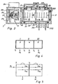
- Fig. 2 is a semi-diagrammatic sectional view of a preferred embodiment of a photoacoustic device 2 according to the invention. It comprises a source 21 of a pulsating beam B of light emanating from an emitter 211, e.g. an incandescent lamp combined with a paraboloid reflector 212 or other paralleling means supported by bracket 215, within enclosure means 22.
- a rotatable bell 213 provided with an opening 216 is connected to motor 214 and is operated in the manner explained above in connection with Fig.1.
- source 21 should be capable of providing a black-body spectrum.
- a detector (not shown in Fig. 2) can be used for monitoring and/or synchronization purposes as explained above.
- Enclosure means 22 serves to integrally connect source 21 of the pulsating beam with cell 23.
- a number of sonic insulators 223, e.g. cushions, sonic blocks or O-rings made of an elastomeric polymer serve to hold cell 23 suspended within enclosure 22, preferably in an essentially coaxial manner with regard to the longitudinal axis of enclosure 22 for simplicity of construction.
- enclosure 22 is of relatively heavy construction, e.g. with a wall thickness in the range of from about 5 - 15 mm, and is made of a relatively "heavy" (i. e. having the capacity of absorbing sonic energy) structural material, such as stainless steel.
- Cell 23 does not need heavy walling and can be made of a light structural metal, such as aluminum, an optionally reinforced synthetic polymer composition or the like.
- An optional filter 26 is provided at the beam entrance end of reference chamber 24 and is made of a material that is selectively transparent to the infrared radiation selected for the particular device 2 considering the nature of the gaseous media within chambers 24 and 25. Selection of a proper filter is known in the photoacoustic art.
- windows 241 near the entrance end of chamber 24 as well as window 254 between chambers 24 and 25 are made of a material that is transparent for infrared radiation but need not be selective.
- measuring chamber 25 can be provided with a mirror (not shown in Fig. 2) for infrared radiation.
- Inlet 251 including a valve and outlet 252, also including a valve, are provided for supplying measuring chamber 25 with a gaseous medium containing the (known) species of interest in an unknown concentration.
- Sonic detectors 27, 28, e.g. microphones of the type known for use in photoacoustics, are provided to detect sonic frequencies produced by the gaseous media in chambers 24, 25 upon the impact of pulsating beam B and the thermal excitation of the gaseous media, or their constituents of interest, produced thereby.
- Signal lines (not shown in Fig. 2) are provided for connection with a signal processing device as explained above.
- enclosure 22 constitutes an integral device which provides a path P for beam B through reference chamber 24 and measuring chamber 25.
- sonic detectors 27, 28 are connected with cell 23 but do not mechanically contact enclosure 22 because of openings 227 and 228 provided in enclosure 22.
- a sonic shield 229 is provided for acoustic protection of detectors 27, 28 against external noise and can be evacuated if desired via an opening 226.
- the inner space of enclosure 22 insofar as not occupied by cell 23 and detectors 27, 28 can be evacuated, maintained under reduced pressure and/or filled with an inert gas. It is to be noted that the device illustrated herein can be said to be of the non-resonant type.
- Fig. 3 is a perspective and semi-diagrammatic view of a preferred embodiment of the pulse generator or "chopper” 3.
- the term “chopper” normally refers to such devices as are used on the top of emergency vehicles emitting flashes of colored light and the structure of such devices is of use in the invention.
- Upper wall 31 is made of a heavy disk, e.g. of stainless steel, which may have a number of equally distanced openings 321 for air cooling of the light source.
- Tubular side wall 32 should be made of a very light and thin material that is not transparent for infrared radiation, e.g. aluminum, in order to minimize the impact of imbalance caused by the absence of wall material in opening 321.
- the opening can be covered with a material that is transparent to infrared radiation and has a mass that is similar to that of an equally dimensioned segment of the material of side wall 32. It is to be noted that side edges of opening 321 can be straight as shown or rounded, depending upon the desired configuration of the light pulses.
- the linear or serial arrangement of reference and measurement chambers in the cell of a device according to the invention vary in essentially the same way in dependence upon external parameters, such as temperature, impact of vibration, extraneous noise etc.
- Fig. 4 shows the diagram of a cell having three chambers, e.g. a first reference chamber I, a first measuring chamber II and an additional chamber III which could be either a reference chamber or a measuring chamber. If chamber III is a second reference cell, such arrangement permits to check the operation of the reference cells as well as the cleanliness of the entrance window of the measuring cell.
- T 1 , T 2 , T 3 indicate the transmission coefficients for mathematical treatment of operation.
- ⁇ and ⁇ indicate the absorption in the particular chamber.
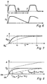
- Fig. 5 is a diagram of a cell in which the pulses P 0 pass through reference chamber R as well as through measuring chamber M, and are reflected at the end of measuring chamber M by means of a mirror (not indicated in Fig. 5).
- Mathematical treatment of the values of reference signals S R1 , S R2 and of measuring signals S M1 , S M2 indicates that information about the cleanliness of the entrance window of measuring chamber M can be obtained by calculating coefficient T 2 .
- Fig. 6 shows two superimposed diagrams in which the ordinate of the upper diagram indicates the light signal L S ; the ordinate of the lower diagram indicates the strength of the acoustic signal A S while the abscissa of both diagrams indicates the chopper cycle T. It can be shown that the acoustic signal optimally is zero when the excitation cycle starts.
- Parameter a/b depends upon the frequency of modulation at ⁇ 100 Hz. For example, an value for a/b of 0.44 can be obtained for a chopper window of 110°.
- Fig. 7 shows a diagram for signal slopes ⁇ 11 and ⁇ 12 ; the ordinate indicates the strength of the acoustic signal A while the abscissa indicates the concentration of the species of analytical interest, e.g. ozone.
- Mathematical analysis indicates that if the cell length is decreased for a given acoustic signal, the measurable concentration range will increase.
Description
- This invention generally relates to the art of analyzing fluids and specifically to photoacoustic devices for quantitative analysis of fluids, normally in a gaseous state.
- The principle common to known photoacoustic devices and methods is interaction of light, generally in the infrared portion of the electromagnetic spectrum, with a gaseous sample containing a known analytic species of interest - which may but need not be an impurity - in an unknown concentration for generating a sonic signal dependent upon the concentration of the species of interest.
- Anal. Chem., vol.54, n°9. August 1982. pg. 1485-1489 discloses a photoacoustic device and a method for detection of NO2 in air samples at a total pressure of about 1 bar using a continuous-wave krypton laser generating a visible pulsating beam of light. and being suitable for passing two cylindrical sample cells of identical design and construction. The device includes a measuring cell filled with NO2 in mixture with air. and a reference cell filled with air only. Both cells are in an essentially linear arrangement. Various types of condenser micro-phones for detection of the photoacoustic signal are tested because of corrosion problems.
- DE 33 45 077 discloses a photoacoustic device and a method for measuring the concentration of a gas in a mixture of gases or of solid particles in a gas using a cell having a gas inlet and a gas outlet for receiving and discharging a gas. and means for directing laser beam from a source into the cell. A chopper is arranged in the path of the laser beam between the device and the cell to generate a frequency corresponding to the resonance frequency of the cell. A microphone is used for detecting the acoustic signal generated by changes of the pressure within the cell. The concentration of the gas. or the concentration of the particles in the gas, is determined from the acoustic signal.
- Research by applicant leading to the present invention has indicated that a major problem with many types of prior art photoacoustic devices is poor reproducibility of results, notably if unstable substances, such as ozone (O3), are the species of interest.
- According to the invention, an analytic species of interest is considered "unstable" if it will or may decompose under the conditions of measurement. Conversely, an analytic species of interest is considered to be "stable" if it does not decompose to a significant degree under the conditions of measurement.
- Even with relatively stable analytical species of interest that are presumed to be inherently suitable for photoacoustic methods (NH3, CO2, H2O, CO, NOx, SOx and various organic substances such as ethylene) problems of sensitivity and reproducibility have been observed. notably when such species were present in relatively high concentrations, e.g. in the range of from 5 to 50% by volume or higher. Also, many prior art devices tend to have a relatively complicated structure and/or require special skill on the side of the operator.
- Accordingly, it is a main object of the present invention to provide for a photoacoustic device that diminishes or eliminates the above-mentioned disadvantages of the prior art.
- This object is achieved by a photoacoustic device for analysis of fluids comprising:
- (A) a source of a pulsating beam of light, e.g. as exemplified hereinbelow;
- (B) an enclosure, preferably an elongated structure having a generally cylindrical, e.g. essentially tubular shape, and containing and holding - in sonic insulation - at least one reference chamber and at least one measuring chamber in an essentially linear or serial arrangement in a common cell within the enclosure means, preferably in an essentially coaxial arrangement; the enclosure means and the common cell provide a path for the pulsating beam of light through the reference chamber and through the measuring chamber. According to the invention, the light beam passes first through the, or a first, reference chamber and subsequently into the measuring chamber. Optionally, a second reference chamber is arranged at the end of the measuring chamber and a second measuring chamber may follow. Theoretically, there is no limit to the number of reference chambers and measuring chambers in alternating arrangements but the use of one or two reference chambers with a subsequent or intermediate measuring chamber is preferred for many purposes.
-
- The measuring chamber or chambers has (have) inlet and outlet means or ports, such as conduits and valves, for passing a gaseous medium containing the known species of interest in an unknown concentration into and out of the measuring chamber; the reference chamber(s) and the measuring chamber(s) each contain a sound detector, such as a microphone or other transducer capable of converting sound within the frequency range generated by the pulsating beam, into an electric signal in relation to the sound. The reference chamber(s) contain(s) a gaseous medium suitable for serving as a photoacoustic reference for the gaseous medium containing the species of interest.
- If the species of interest is "stable" (no significant decomposition under the conditions of measurement) the gaseous medium in the reference chamber preferably contains the same constituents as the gaseous medium in the measuring chamber. With chemically unstable substances, such as ozone, as the species of interest the reference chamber preferably contains an essentially stable or inert gaseous medium that is suitable as a photoacoustic reference; such suitability or compatibility for use as a reference is understood in the photoacoustic art and is based upon similarity or compatibility of absorption, e.g similar absorption in the same infrared frequency band. For example, various and normally gaseous organic substances, such as alkanes, e.g. propane, are suitable for use in the reference chamber when ozone is the species of interest.
- Conventional electronic signal processors can be used to amplify and/or convert the output signal of the sound detectors or microphones into the desired units of measurement, e.g. parts per million, percents, weight units per volume, units of partial pressure, or the like. A part or all of the electronic signal processing means could be integrated into the analyzer according to the invention but this is not generally preferred because one and the same processor can be used in combination with a number of analytic devices for use in detecting specific species of interest and, hence, including different gaseous media in the reference chamber(s).
- When analyzing samples that contain ozone or another unstable species of interest, the rate of decay of the chemically reactive substance may be used for calibration of said analytic device. Such rate of decay can be determined under laboratory conditions for a given configuration of the device according to the invention and used under field conditions for calibrating the instrument.
- The invention will now be illustrated by way of example with reference to the enclosed drawings in which:
- Figure 1 is a diagrammatic view of an analytic system including a photoacoustic device according to the invention;
- Figure 2 is a diagrammatic sectional view of a preferred embodiment of the photoacoustic device according to the invention;
- Figure 3 is a semi-diagrammatic perspective view of a preferred embodiment of the light source for a device according to the invention;
- Figure 4 is a diagram illustrating a linear or serial arrangement of two reference chambers and an intermediate measuring chamber for a photoacoustic device according to the invention;
- Figure 5 is a diagrammatic illustration of the passage of the light beam when using a light-reflective layer at the end of the measuring chamber;
- Figures 5 through 8 show a number of graphs for illustrating certain concepts when operating preferred embodiments of the invention; and
- Figures 9 and 10 illustrate optional modifications of the measuring chamber in a device according to the invention.
-
- The
analytic system 1 shown diagrammatically in Fig. 1 comprises a cell 11 having ameasuring chamber 111 and areference chamber 112 in linear or serial arrangement according to the invention. Asource 12 of a pulsating, i.e. modulated, beam of light comprises alight source 122, e.g. an incandescent lamp or another emitter of electromagnetic radiation in the infrared region typically in the range of from about 3 • 1011 to about 3.8 • 1014 Hz. A filter (not shown in Fig. 1) may be used to select a specific range dependent in a manner known per se upon the gaseous medium under consideration. Generally, a frequency band having a high efficiency of transfer of light energy into thermal energy for the specific gaseous medium will be selected in a manner known per se in the photoacoustic art. Anoptional photodetector 13 may be provided for synchronization purposes and/or for monitoring the pulse frequency, and apower supply line 126 forlight source 122 as well as asignal line 131 ofdetector 13 will be provided for operation. - A
bell 123, e.g. of an essentially tubular configuration, having at least one perforation or opening 124 is connected to a drive 121, e.g. an electric motor. As theperforated bell 123 rotates with a predetermined and essentially constant rotational speed, e.g. 600 rpm, a modulated beam of light pulsating at a predetermined rate, e.g. 10 Hz, will be produced by the emitter orsource 12. - The pulsating beam passes through an optional filter (not shown in Fig. 1) through a
window 116 intoreference chamber 112 and through asecond window 115 intomeasuring chamber 111. Cell 11 is arranged within an enclosure (not shown in Fig. 1) in a manner explained in more detail below. Windows 115, 116 are made of a material that permits passage of infrared radiation. Such materials (also termed electroacoustic substrates) are known in the art, e.g. as referenced above, and include such substances as zinc selenide, gallium arsenide, and germanium. - Each
chamber sound detector -
Measuring chamber 111 is connected with aninlet conduit 141 that can be opened and closed by a valve 14 which is connected with a source of the gas containing the analytic species of interest, optionally viapump 18. Chamber 11 is also connected with anoutlet conduit 151 with associatedvalve 15 and aventing line 16. Preferably, both valves are automated valves for control via lines 171, 172. - Upon operation of
system 1, the output signal S ofdetector 113 as well as the reference signal R are fed into a conventional signal processing and control unit 19; such units are available commercially, e.g. under the trade name MOCA, analyzer model 3610, from Orbisphere Laboratories, Neuchâtel, Switzerland. - Fig. 2 is a semi-diagrammatic sectional view of a preferred embodiment of a
photoacoustic device 2 according to the invention. It comprises asource 21 of a pulsating beam B of light emanating from anemitter 211, e.g. an incandescent lamp combined with a paraboloid reflector 212 or other paralleling means supported bybracket 215, within enclosure means 22. Arotatable bell 213 provided with anopening 216 is connected tomotor 214 and is operated in the manner explained above in connection with Fig.1. Generally,source 21 should be capable of providing a black-body spectrum. A detector (not shown in Fig. 2) can be used for monitoring and/or synchronization purposes as explained above. - Enclosure means 22 serves to integrally connect
source 21 of the pulsating beam withcell 23. A number ofsonic insulators 223, e.g. cushions, sonic blocks or O-rings made of an elastomeric polymer serve to holdcell 23 suspended withinenclosure 22, preferably in an essentially coaxial manner with regard to the longitudinal axis ofenclosure 22 for simplicity of construction. - Preferably,
enclosure 22 is of relatively heavy construction, e.g. with a wall thickness in the range of from about 5 - 15 mm, and is made of a relatively "heavy" (i. e. having the capacity of absorbing sonic energy) structural material, such as stainless steel.Cell 23, on the other hand, does not need heavy walling and can be made of a light structural metal, such as aluminum, an optionally reinforced synthetic polymer composition or the like. - An
optional filter 26 is provided at the beam entrance end ofreference chamber 24 and is made of a material that is selectively transparent to the infrared radiation selected for theparticular device 2 considering the nature of the gaseous media withinchambers windows 241 near the entrance end ofchamber 24 as well aswindow 254 betweenchambers - The backside end of measuring
chamber 25 can be provided with a mirror (not shown in Fig. 2) for infrared radiation.Inlet 251 including a valve andoutlet 252, also including a valve, are provided for supplying measuringchamber 25 with a gaseous medium containing the (known) species of interest in an unknown concentration. -
Sonic detectors chambers enclosure 22 constitutes an integral device which provides a path P for beam B throughreference chamber 24 and measuringchamber 25. - As is also apparent from Fig. 2,
sonic detectors cell 23 but do not mechanically contactenclosure 22 because ofopenings enclosure 22. A sonic shield 229 is provided for acoustic protection ofdetectors enclosure 22 insofar as not occupied bycell 23 anddetectors - Fig. 3 is a perspective and semi-diagrammatic view of a preferred embodiment of the pulse generator or "chopper" 3. The term "chopper" normally refers to such devices as are used on the top of emergency vehicles emitting flashes of colored light and the structure of such devices is of use in the invention. Upper wall 31 is made of a heavy disk, e.g. of stainless steel, which may have a number of equally distanced
openings 321 for air cooling of the light source.Tubular side wall 32, on the other hand, should be made of a very light and thin material that is not transparent for infrared radiation, e.g. aluminum, in order to minimize the impact of imbalance caused by the absence of wall material inopening 321. Alternatively, the opening can be covered with a material that is transparent to infrared radiation and has a mass that is similar to that of an equally dimensioned segment of the material ofside wall 32. It is to be noted that side edges of opening 321 can be straight as shown or rounded, depending upon the desired configuration of the light pulses. - Generally, the linear or serial arrangement of reference and measurement chambers in the cell of a device according to the invention vary in essentially the same way in dependence upon external parameters, such as temperature, impact of vibration, extraneous noise etc.
- Fig. 4 shows the diagram of a cell having three chambers, e.g. a first reference chamber I, a first measuring chamber II and an additional chamber III which could be either a reference chamber or a measuring chamber. If chamber III is a second reference cell, such arrangement permits to check the operation of the reference cells as well as the cleanliness of the entrance window of the measuring cell.
- T1, T2, T3 indicate the transmission coefficients for mathematical treatment of operation. α and β indicate the absorption in the particular chamber.
- Fig. 5 is a diagram of a cell in which the pulses P0 pass through reference chamber R as well as through measuring chamber M, and are reflected at the end of measuring chamber M by means of a mirror (not indicated in Fig. 5). Mathematical treatment of the values of reference signals SR1, SR2 and of measuring signals SM1, SM2 indicates that information about the cleanliness of the entrance window of measuring chamber M can be obtained by calculating coefficient T2.
- Fig. 6 shows two superimposed diagrams in which the ordinate of the upper diagram indicates the light signal LS; the ordinate of the lower diagram indicates the strength of the acoustic signal AS while the abscissa of both diagrams indicates the chopper cycle T. It can be shown that the acoustic signal optimally is zero when the excitation cycle starts. Parameter a/b depends upon the frequency of modulation at < 100 Hz. For example, an value for a/b of 0.44 can be obtained for a chopper window of 110°.
- Fig. 7 shows a diagram for signal slopes σ11 and σ12; the ordinate indicates the strength of the acoustic signal A while the abscissa indicates the concentration of the species of analytical interest, e.g. ozone. Mathematical analysis indicates that if the cell length is decreased for a given acoustic signal, the measurable concentration range will increase.
- This can be applied in a measuring chamber according to the invention as illustrated in Figures 9 and 10, where the effective cell length "l" is decreased by insertion of a metallic stopper body b (Fig.9) or a body b' so as to produce a measuring chamber with two differing path lengths l1 and l2.
- Figure 8 is a diagram similar to that shown in Fig. 7 and indicates that maximum of detectivity (maximum detectable concentration) can be increased in this manner. For example, with l = 40 mm, a detectable concentration limit of 5 % was observed for ozone whereas with l = 20 mm, the detectable concentration limit was 10%. Accordingly, an insert of the type shown in Fig. 10 permits to increase the maximum of detectivity without changing the minimum of detectivity.
Claims (10)
- A photoacoustic device (2) for analysis of fluids comprising:characterised in that(A) a source (21) of a pulsating beam of light(B) an enclosure means (22) containing:at least one reference chamber (24) and at least one measuring chamber (25) in an essentially linear arrangement within said enclosure means:
- (B-1)
- said enclosure means providing a path (P) for said pulsating beam of light through said at least one reference chamber and through said at least one measuring chamber; said at least one measuring chamber having inlet and outlet means (251, 252) for passing a gaseous medium containing a species of interest in an unknown concentration into and out of said at least one measuring chamber;
- (B-2)
- said at least one reference chamber and said at least one measuring chamber each comprising a sound detecting means (27, 28) for detecting sound generated by said pulsating beam of light in said at least one reference chamber and in said at least one measuring chamber; each of said sound detecting means being capable of producing a signal in relation to said sound; and
- (B-3)
- said at least one reference chamber containing a gaseous medium for serving as a photoacoustic reference for said gaseous medium containing said species of interest;
said pulsating beam of light passes through the at least one reference chamber (24) first and subsequently through said at least one measuring chamber; and
said reference chamber (24) and said measurement chamber (25) are in a common cell (23) within said enclosure means (22). - The device of claim 1 further comprising means (19) for evaluating said signal generated by each of said sound detecting means (113, 114) in relation with said unknown concentration of said species of interest.
- The device of claim 1 or 2 wherein said source (12) of said pulsating beam of light comprises: a light source (122) capable of emitting light in an infrared wave length portion; and a chopper means (121, 123, 124) encompassing said light source, and having a rotatable shield (123) and a drive (121) capable of causing said shield to rotate at a predetermined speed of rotation; said shield having an opening (121) to cause modulation of the light source at a frequency related to said predetermined speed of rotation.
- The device of any of claims 1 - 3 wherein said at least one reference chamber (112) is arranged between said source (12) of said pulsating light beam and said measuring chamber (111).
- The device of any of claims 1 - 4 wherein said at least one reference chamber (24) has a first window (241) for permitting entrance of said pulsating light beam and a second window (254) for permitting passage of said pulsating light beam from said reference chamber into said measuring chamber (25); both said first and said second windows being made of a material that is capable of transmitting infrared light but is essentially impermeable for said gaseous medium in said reference chamber.
- The device of any of claims 1 - 5 comprising in said linear arrangement and in sequence a first reference chamber (R1), said at least one measuring chamber (M), and a second reference chamber (R2); said measuring chamber having a window for permitting passage of infrared light into said second reference chamber.
- The device of any of claims 1 - 6 wherein said enclosure means (22) has an essentially elongated cylindrical external shape; said common cell (23) also having an essentially elongated cylindrical external shape and being arranged essentially coaxially with said enclosure means.
- The device of any of claims 3 - 7 wherein an optical filter (26) is arranged between said light source (21) and said first window (241).
- The device of any of claims 1 - 8 wherein said cell (23) is held in position within said enclosure (22) by means of acoustic dampening elements (223).
- The device of any of claims 1 - 9 wherein said sound detecting means (227, 228) are in physical contact with said cell (23) but not in physical contact with said enclosure (22); and wherein an acoustic shield (229) is provided on said enclosure for protecting unwanted sound input to said sound detecting means.
Priority Applications (4)
| Application Number | Priority Date | Filing Date | Title |
|---|---|---|---|
| DE69431873T DE69431873T2 (en) | 1994-06-04 | 1994-06-04 | Photoacoustic analyzer |
| EP94810332A EP0685728B1 (en) | 1994-06-04 | 1994-06-04 | Photoacoustic analyzer |
| US08/443,533 US5616826A (en) | 1994-06-04 | 1995-05-18 | Photoacoustic analyzer and method |
| JP13821095A JP3627112B2 (en) | 1994-06-04 | 1995-06-05 | Photoacoustic analyzer and analysis method |
Applications Claiming Priority (1)
| Application Number | Priority Date | Filing Date | Title |
|---|---|---|---|
| EP94810332A EP0685728B1 (en) | 1994-06-04 | 1994-06-04 | Photoacoustic analyzer |
Publications (2)
| Publication Number | Publication Date |
|---|---|
| EP0685728A1 EP0685728A1 (en) | 1995-12-06 |
| EP0685728B1 true EP0685728B1 (en) | 2002-12-11 |
Family
ID=8218266
Family Applications (1)
| Application Number | Title | Priority Date | Filing Date |
|---|---|---|---|
| EP94810332A Expired - Lifetime EP0685728B1 (en) | 1994-06-04 | 1994-06-04 | Photoacoustic analyzer |
Country Status (4)
| Country | Link |
|---|---|
| US (1) | US5616826A (en) |
| EP (1) | EP0685728B1 (en) |
| JP (1) | JP3627112B2 (en) |
| DE (1) | DE69431873T2 (en) |
Families Citing this family (46)
| Publication number | Priority date | Publication date | Assignee | Title |
|---|---|---|---|---|
| NO300346B1 (en) * | 1995-04-05 | 1997-05-12 | Sinvent As | Photo-acoustic measuring device |
| ATE266861T1 (en) * | 1995-09-04 | 2004-05-15 | Siemens Building Tech Ag | PHOTOACOUSTIC GAS SENSOR AND USE THEREOF |
| NO963924A (en) * | 1996-09-19 | 1997-12-15 | Nyfotek As | Photo-acoustic infrared detector |
| EP0840105A1 (en) | 1996-11-05 | 1998-05-06 | Orbisphere Laboratories Neuchatel Sa | Spectroscopic method and apparatus |
| DE59712692D1 (en) * | 1997-01-25 | 2006-08-24 | Siemens Schweiz Ag | Optoacoustic gas sensor |
| US5780724A (en) * | 1997-03-27 | 1998-07-14 | United Technologies Corp | Photo-acoustic leak detector with improved signal-to-noise response |
| US5852308A (en) * | 1997-06-30 | 1998-12-22 | Honeywell Inc. | Micromachined inferential opto-thermal gas sensor |
| US6039055A (en) * | 1998-01-08 | 2000-03-21 | International Business Machines Corporation | Wafer cleaning with dissolved gas concentration control |
| AU3279099A (en) * | 1998-02-26 | 1999-09-15 | Presens As | A method for drift compensated measurement of gas concentration, and a photoacoustical gas sensor |
| US6154307A (en) * | 1998-09-18 | 2000-11-28 | United Technologies Corporation | Method and apparatus to diffract multiple beams |
| US6089076A (en) * | 1998-09-18 | 2000-07-18 | United Technologies Corporation | System to control the power of a beam |
| US6244101B1 (en) * | 1999-06-01 | 2001-06-12 | Battelle Memorial Institute | Photoacoustic method for measuring concentration of chemical species |
| US6612306B1 (en) | 1999-10-13 | 2003-09-02 | Healthetech, Inc. | Respiratory nitric oxide meter |
| WO2001046669A2 (en) * | 1999-10-25 | 2001-06-28 | Interwoven Technologies Corporation | System and method for characterizing and identifying agents |
| DK173775B1 (en) * | 2000-01-14 | 2001-10-08 | Pas Technology As | gas analyzer |
| US7034943B1 (en) * | 2000-03-03 | 2006-04-25 | Aritron Intrumente AG | Gas sensors |
| US6408681B1 (en) * | 2000-03-23 | 2002-06-25 | The United States Of America As Represented By The Secretary Of The Army | Single particle photoacoustic absorption spectrometer |
| WO2002026112A2 (en) | 2000-09-29 | 2002-04-04 | Healthetech, Inc. | Indirect calorimetry system |
| US6662627B2 (en) * | 2001-06-22 | 2003-12-16 | Desert Research Institute | Photoacoustic instrument for measuring particles in a gas |
| US7064329B2 (en) * | 2001-08-21 | 2006-06-20 | Franalytica, Inc. | Amplifier-enhanced optical analysis system and method |
| HU225660B1 (en) * | 2002-05-24 | 2007-05-29 | Mol Magyar Olaj & Gazipari Rt | Method for photoacoustic measurement of concentration of non hydrocarbon component of gas mixture containing methane |
| WO2004008113A1 (en) * | 2002-07-12 | 2004-01-22 | Abb Research Ltd | Absorption spectrometer and corresponding measuring method |
| WO2004008112A1 (en) * | 2002-07-12 | 2004-01-22 | Abb Research Ltd | High-resolution absorption spectrometer and corresponding measuring method |
| EP1797478A4 (en) * | 2004-10-04 | 2009-07-15 | Univ South Carolina | Thermal selectivity multivariate optical computing |
| US8325343B2 (en) * | 2010-02-16 | 2012-12-04 | Honeywell International Inc. | Detector for cavity ring-down spectroscopy |
| US8695402B2 (en) * | 2010-06-03 | 2014-04-15 | Honeywell International Inc. | Integrated IR source and acoustic detector for photoacoustic gas sensor |
| US8434366B2 (en) | 2010-12-15 | 2013-05-07 | Texas Instruments Incorporated | Active detection techniques for photoacoustic sensors |
| US8701465B2 (en) * | 2011-04-28 | 2014-04-22 | Honeywell International Inc. | Photoacoustic sensor diffusion membrane attachment structure |
| US9380981B2 (en) | 2013-03-15 | 2016-07-05 | Covidien Lp | Photoacoustic monitoring technique with noise reduction |
| GB201312046D0 (en) * | 2013-07-04 | 2013-08-21 | Sonex Metrology Ltd | An acoustic isolation chamber |
| US9513261B2 (en) | 2013-10-14 | 2016-12-06 | Infineon Technologies Ag | Photoacoustic gas sensor device and a method for analyzing gas |
| US9570659B2 (en) * | 2013-10-14 | 2017-02-14 | Infineon Technologies Ag | Semiconductor device for emitting frequency-adjusted infrared light |
| US10883875B2 (en) | 2015-03-05 | 2021-01-05 | Honeywell International Inc. | Use of selected glass types and glass thicknesses in the optical path to remove cross sensitivity to water absorption peaks |
| DE202015002315U1 (en) * | 2015-03-27 | 2015-05-06 | Infineon Technologies Ag | gas sensor |
| CA2981647C (en) | 2015-04-02 | 2023-08-01 | The Curators Of The University Of Missouri | Photoacoustic flow cell for identification of rare analytes in suspension |
| DE102015106373B4 (en) | 2015-04-24 | 2023-03-02 | Infineon Technologies Ag | PHOTOACOUSTIC GAS SENSOR MODULE WITH LIGHT EMITTER UNIT AND DETECTOR UNIT |
| CN108351293A (en) | 2015-09-10 | 2018-07-31 | 霍尼韦尔国际公司 | Detector with normalized response and improvement sensitivity |
| WO2017062626A1 (en) | 2015-10-09 | 2017-04-13 | Honeywell International Inc. | Electromagnetic radiation detector using a planar golay cell |
| DE102016103646B4 (en) * | 2016-01-22 | 2023-03-02 | Infineon Technologies Ag | INTEGRATED PHOTOACOUSTIC GAS SENSOR MODULE |
| US10302599B2 (en) * | 2016-10-27 | 2019-05-28 | Infineon Technologies Ag | Photoacoustic gas detector |
| US10620165B2 (en) * | 2016-12-29 | 2020-04-14 | Infineon Technologies Ag | Photoacoustic gas analyzer for determining species concentrations using intensity modulation |
| CN107817219A (en) * | 2017-12-05 | 2018-03-20 | 北京国网富达科技发展有限责任公司 | A kind of twin-stage enhanced photo acoustic spectroscopic detector device and its detection method |
| EP3561487B1 (en) * | 2018-04-25 | 2023-01-18 | ABB Schweiz AG | Measuring device for analysis of a composition of a combustible gas with a filter chamber arranged in front of a detector |
| KR102005486B1 (en) * | 2018-10-23 | 2019-07-30 | 한국수력원자력 주식회사 | Photoacoustic spectroscopy for analyzing dissolved gas improved reliability |
| DE102021117510A1 (en) | 2021-07-07 | 2023-01-12 | FR Vermögensverwaltung GbR Vertretungsberechtigte Gesellschafter: Franziska Michl, Kirchsteig 44, 95679 Waldershof /Raimund Hoffmann, Beethovenstraße 20, 95632 Wunsiedel | Analysis device and method for determining a vibration pattern of a substance |
| CN116930091B (en) * | 2023-09-14 | 2023-12-12 | 武汉理通微芬科技有限公司 | Gas analysis device based on non-resonance photoacoustic cell |
Family Cites Families (21)
| Publication number | Priority date | Publication date | Assignee | Title |
|---|---|---|---|---|
| US2106612A (en) * | 1935-08-06 | 1938-01-25 | Gen Electric | Straightener for woven material |
| SU116724A1 (en) * | 1956-05-14 | 1957-11-30 | П.И. Бреслер | Gas analyzer |
| SU449286A1 (en) * | 1972-05-29 | 1974-11-05 | Специальное Конструкторско-Технологическое Бюро Медицинских И Физиологических Приборов | Optical-acoustic gas analyzer |
| US3820901A (en) * | 1973-03-06 | 1974-06-28 | Bell Telephone Labor Inc | Measurement of concentrations of components of a gaseous mixture |
| US3948345A (en) * | 1973-06-15 | 1976-04-06 | Allan Rosencwaig | Methods and means for analyzing substances |
| US3938365A (en) * | 1973-11-29 | 1976-02-17 | Massachusetts Institute Of Technology | Detecting trace gaseous species acoustically in response to radiation from an intense light source |
| DE2508637C3 (en) * | 1975-02-28 | 1979-11-22 | Max-Planck-Gesellschaft Zur Foerderung Der Wissenschaften E.V., 3400 Goettingen | Arrangement for the optical measurement of blood gases |
| US4027972A (en) * | 1976-03-31 | 1977-06-07 | Andros Incorporated | Gas analyzer method and apparatus |
| US4163382A (en) * | 1978-04-28 | 1979-08-07 | The United States Of America As Represented By The United States Department Of Energy | Method and apparatus for optoacoustic spectroscopy |
| GB2059574A (en) * | 1979-06-25 | 1981-04-23 | Thermo Electron Corp | Absorption cell gas monitor |
| JPS595939A (en) * | 1982-07-03 | 1984-01-12 | Horiba Ltd | Continuous measuring apparatus for particulate |
| JPS5994027A (en) * | 1982-11-20 | 1984-05-30 | Horiba Ltd | Optoacoustic effect type measuring apparatus |
| US5030420A (en) * | 1982-12-23 | 1991-07-09 | University Of Virginia Alumni Patents Foundation | Apparatus for oxygen determination |
| JPS59145957A (en) * | 1983-01-08 | 1984-08-21 | Horiba Ltd | Opto-acoustic type concentration measuring device |
| US4622845A (en) * | 1985-03-21 | 1986-11-18 | Westinghouse Electric Corp. | Method and apparatus for the detection and measurement of gases |
| DE3617763A1 (en) * | 1985-05-28 | 1986-12-04 | Olympus Optical Co., Ltd., Tokio/Tokyo | METHOD FOR CARRYING OUT IMMUNOLOGICAL PROVISIONS AND APPARATUS APPARATUS FOR THIS |
| IL77494A (en) * | 1986-01-01 | 1989-12-15 | Irad Technologies Ltd | Gas analyzer |
| DK247786D0 (en) * | 1986-05-27 | 1986-05-27 | Brueel & Kjaer As | PHOTOACUSTIC GAS ANALYZER |
| DK160590C (en) * | 1988-09-12 | 1991-09-16 | Fls Airloq As | METHOD OF DETECTING A GAS TYPE BY PHOTOACUSTIC SPECTROSCOPY |
| US5003488A (en) * | 1989-03-10 | 1991-03-26 | Gespac, Inc. | Automatic fluid sedimentation rate measurement apparatus and method |
| DE4034375A1 (en) * | 1990-10-29 | 1992-04-30 | Diehl Gmbh & Co | Acousto=optical gas measuring device - with pollutant enrichment cell preceding measuring chamber |
-
1994
- 1994-06-04 EP EP94810332A patent/EP0685728B1/en not_active Expired - Lifetime
- 1994-06-04 DE DE69431873T patent/DE69431873T2/en not_active Expired - Fee Related
-
1995
- 1995-05-18 US US08/443,533 patent/US5616826A/en not_active Expired - Fee Related
- 1995-06-05 JP JP13821095A patent/JP3627112B2/en not_active Expired - Fee Related
Also Published As
| Publication number | Publication date |
|---|---|
| JP3627112B2 (en) | 2005-03-09 |
| JPH07333139A (en) | 1995-12-22 |
| DE69431873T2 (en) | 2003-11-13 |
| DE69431873D1 (en) | 2003-01-23 |
| EP0685728A1 (en) | 1995-12-06 |
| US5616826A (en) | 1997-04-01 |
Similar Documents
| Publication | Publication Date | Title |
|---|---|---|
| EP0685728B1 (en) | Photoacoustic analyzer | |
| JP5022363B2 (en) | Photoacoustic detector and photoacoustic detection method | |
| CA1254281A (en) | Method and apparatus for the detection and measurement of gases | |
| CN101458234B (en) | Portable power transformer fault diagnostic apparatus | |
| US4594004A (en) | Continuous particulate-measuring apparatus using an optoacoustic effect | |
| US5341214A (en) | NDIR gas analysis using spectral ratioing technique | |
| Adams et al. | Analytical optoacoustic spectrometry. Part I. Instrument assembly and performance characteristics | |
| CN101213438B (en) | Photo-acoustic spectrometer apparatus | |
| US7170607B2 (en) | Gas identification device | |
| Adams | Real-time in situ measurements of atmospheric optical absorption in the visible via photoacoustic spectroscopy. 1: Evaluation of photoacoustic cells | |
| JPH05503352A (en) | Gas detector using infrared rays | |
| JPH0464023B2 (en) | ||
| JPS62212551A (en) | Gas chamber for test used for spectrometer | |
| US3899252A (en) | Ndir gas analyzer based on absorption modulation ratios for known and unknown samples | |
| EP0518993B1 (en) | Method and apparatus for the transmission of an acoustic signal in a photoacoustic cell | |
| CN112924388A (en) | Orthogonal dual channel acoustic resonance module and device comprising same | |
| GB2358245A (en) | Photo-acoustic gas sensor | |
| Rosencwaig | Photo‐acoustic spectroscopy of solids | |
| JPS6238345A (en) | Method and instrument for analyzing solid particles | |
| WO1996001418A1 (en) | Ndir gas analysis using spectral ratioing technique | |
| CA1122432A (en) | Resonant subcavity differential spectrophone | |
| US3920993A (en) | Piggyback optical bench | |
| Betteridge et al. | Analytical aspects of photoacoustic spectroscopy | |
| McClelland et al. | A tutorial on the state-of-the art of ftir photoacoustic spectroscopy | |
| CN218412261U (en) | Hydrogen sulfide gas detection device based on ultraviolet dual-wavelength correlation spectroscopy |
Legal Events
| Date | Code | Title | Description |
|---|---|---|---|
| PUAI | Public reference made under article 153(3) epc to a published international application that has entered the european phase |
Free format text: ORIGINAL CODE: 0009012 |
|
| AK | Designated contracting states |
Kind code of ref document: A1 Designated state(s): CH DE FR GB LI |
|
| 17P | Request for examination filed |
Effective date: 19951120 |
|
| RBV | Designated contracting states (corrected) |
Designated state(s): CH DE FR GB LI |
|
| 17Q | First examination report despatched |
Effective date: 20020125 |
|
| GRAG | Despatch of communication of intention to grant |
Free format text: ORIGINAL CODE: EPIDOS AGRA |
|
| GRAG | Despatch of communication of intention to grant |
Free format text: ORIGINAL CODE: EPIDOS AGRA |
|
| GRAH | Despatch of communication of intention to grant a patent |
Free format text: ORIGINAL CODE: EPIDOS IGRA |
|
| RTI1 | Title (correction) |
Free format text: PHOTOACOUSTIC ANALYZER |
|
| GRAH | Despatch of communication of intention to grant a patent |
Free format text: ORIGINAL CODE: EPIDOS IGRA |
|
| GRAA | (expected) grant |
Free format text: ORIGINAL CODE: 0009210 |
|
| AK | Designated contracting states |
Kind code of ref document: B1 Designated state(s): CH DE FR GB LI |
|
| REG | Reference to a national code |
Ref country code: GB Ref legal event code: FG4D |
|
| REG | Reference to a national code |
Ref country code: CH Ref legal event code: EP |
|
| REF | Corresponds to: |
Ref document number: 69431873 Country of ref document: DE Date of ref document: 20030123 |
|
| REG | Reference to a national code |
Ref country code: CH Ref legal event code: NV Representative=s name: RITSCHER & PARTNER AG PATENTANWAELTE |
|
| ET | Fr: translation filed | ||
| PLBE | No opposition filed within time limit |
Free format text: ORIGINAL CODE: 0009261 |
|
| STAA | Information on the status of an ep patent application or granted ep patent |
Free format text: STATUS: NO OPPOSITION FILED WITHIN TIME LIMIT |
|
| 26N | No opposition filed |
Effective date: 20030912 |
|
| REG | Reference to a national code |
Ref country code: CH Ref legal event code: PCAR Free format text: RITSCHER & PARTNER AG;RESIRAIN 1;8125 ZOLLIKERBERG (CH) |
|
| PGFP | Annual fee paid to national office [announced via postgrant information from national office to epo] |
Ref country code: CH Payment date: 20080619 Year of fee payment: 15 |
|
| PGFP | Annual fee paid to national office [announced via postgrant information from national office to epo] |
Ref country code: DE Payment date: 20080626 Year of fee payment: 15 |
|
| PGFP | Annual fee paid to national office [announced via postgrant information from national office to epo] |
Ref country code: FR Payment date: 20080529 Year of fee payment: 15 |
|
| PGFP | Annual fee paid to national office [announced via postgrant information from national office to epo] |
Ref country code: GB Payment date: 20080611 Year of fee payment: 15 |
|
| REG | Reference to a national code |
Ref country code: CH Ref legal event code: PL |
|
| GBPC | Gb: european patent ceased through non-payment of renewal fee |
Effective date: 20090604 |
|
| REG | Reference to a national code |
Ref country code: FR Ref legal event code: ST Effective date: 20100226 |
|
| PG25 | Lapsed in a contracting state [announced via postgrant information from national office to epo] |
Ref country code: LI Free format text: LAPSE BECAUSE OF NON-PAYMENT OF DUE FEES Effective date: 20090630 Ref country code: FR Free format text: LAPSE BECAUSE OF NON-PAYMENT OF DUE FEES Effective date: 20090630 Ref country code: CH Free format text: LAPSE BECAUSE OF NON-PAYMENT OF DUE FEES Effective date: 20090630 |
|
| PG25 | Lapsed in a contracting state [announced via postgrant information from national office to epo] |
Ref country code: GB Free format text: LAPSE BECAUSE OF NON-PAYMENT OF DUE FEES Effective date: 20090604 |
|
| PG25 | Lapsed in a contracting state [announced via postgrant information from national office to epo] |
Ref country code: DE Free format text: LAPSE BECAUSE OF NON-PAYMENT OF DUE FEES Effective date: 20100101 |