EP0685603B1 - Multi-shaft excavating device - Google Patents
Multi-shaft excavating device Download PDFInfo
- Publication number
- EP0685603B1 EP0685603B1 EP94902105A EP94902105A EP0685603B1 EP 0685603 B1 EP0685603 B1 EP 0685603B1 EP 94902105 A EP94902105 A EP 94902105A EP 94902105 A EP94902105 A EP 94902105A EP 0685603 B1 EP0685603 B1 EP 0685603B1
- Authority
- EP
- European Patent Office
- Prior art keywords
- transfer means
- shaft
- drive transfer
- auger shafts
- auger
- Prior art date
- Legal status (The legal status is an assumption and is not a legal conclusion. Google has not performed a legal analysis and makes no representation as to the accuracy of the status listed.)
- Expired - Lifetime
Links
Images


Classifications
-
- E—FIXED CONSTRUCTIONS
- E21—EARTH OR ROCK DRILLING; MINING
- E21B—EARTH OR ROCK DRILLING; OBTAINING OIL, GAS, WATER, SOLUBLE OR MELTABLE MATERIALS OR A SLURRY OF MINERALS FROM WELLS
- E21B17/00—Drilling rods or pipes; Flexible drill strings; Kellies; Drill collars; Sucker rods; Cables; Casings; Tubings
- E21B17/22—Rods or pipes with helical structure
-
- E—FIXED CONSTRUCTIONS
- E02—HYDRAULIC ENGINEERING; FOUNDATIONS; SOIL SHIFTING
- E02D—FOUNDATIONS; EXCAVATIONS; EMBANKMENTS; UNDERGROUND OR UNDERWATER STRUCTURES
- E02D17/00—Excavations; Bordering of excavations; Making embankments
- E02D17/13—Foundation slots or slits; Implements for making these slots or slits
-
- E—FIXED CONSTRUCTIONS
- E02—HYDRAULIC ENGINEERING; FOUNDATIONS; SOIL SHIFTING
- E02D—FOUNDATIONS; EXCAVATIONS; EMBANKMENTS; UNDERGROUND OR UNDERWATER STRUCTURES
- E02D5/00—Bulkheads, piles, or other structural elements specially adapted to foundation engineering
- E02D5/18—Bulkheads or similar walls made solely of concrete in situ
-
- E—FIXED CONSTRUCTIONS
- E21—EARTH OR ROCK DRILLING; MINING
- E21B—EARTH OR ROCK DRILLING; OBTAINING OIL, GAS, WATER, SOLUBLE OR MELTABLE MATERIALS OR A SLURRY OF MINERALS FROM WELLS
- E21B7/00—Special methods or apparatus for drilling
- E21B7/001—Drilling a non circular hole
Definitions
- the present invention relates to a multi-shaft drilling apparatus having three rotatable auger shafts, for use in forming a continuous wall under the ground.
- a soil mixing process has been widely used for forming such a wall.
- subsoil is drilled in a wall shape and a mixed liquid containing cement or the like is supplied from an end of an auger shaft to mix with the in-situ soil to develop a continuous wall, which can be a cut-off wall or a retaining wall or shoring in underground works of civil engineering.
- a drive unit 3 is mounted to move vertically on a guide post 2 mounted on a crawler truck 1
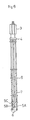
- a multi-shaft drilling apparatus 4 is connected to the lower part of said drive unit 3, and a plurality of auger shafts (three in this embodiment) 5A, 5B and 5C are provided in said multi-shaft apparatus 4.
- a drilling cutter 6 is mounted at the lower end of each auger shaft nothing 5. Screw type blades 7, whose diameter is the same as the drilling cutters 6, and bar-shaped auger blades 8 are alternately located above each drilling cutter 6.
- the auger blades cooperate reciprocally to form a continuous wall unit by mixing the in-situ soil with mixed liquid as aforesaid. If necessary, water retention and sealing ability may be improved by molding H-type steels or sheet piles to the said continuous wall.
- JP-U-5-054637 and JP-A-5-179649 disclose other examples of multi-shaft drilling units for forming a continuous wall under the ground.
- an object of the present invention is to provide an improved multi-shaft drilling apparatus for forming a continuous wall in a straight line.
- a multi-shaft drilling apparatus having three auger shafts, for forming a continuous wall under the ground, said apparatus including a housing arranged to maintain the pitch between said auger shafts, said housing incorporating:
- gears are used as the said first and second drive transfer means, and bevel gears are used as the third and fourth drive transfer means.
- the said cone-shaped cutters are formed as circular cones and as truncated cones.
- a guide shaft is preferably provided at one end of the drilling unit, the said drilling shafts being arranged in a line. Such a guide shaft can be provided at both ends of the unit.
- a jet nozzle is preferably provided on the or each said guide shaft, said nozzle preferably being on a tangent line to the outside of the guide shaft.
- the or each guide shaft is preferably provided with a tubular guide bit formed with a concavity which partially embraces a bit of the adjacent drilling shaft.
- a multi-shaft drilling apparatus constructed as above enables a triangular region of soil, which has conventionally remained, to be completely cut off by the said cutters, whereby a continuous wall unit with semicircular ends and straight sides can be formed.
- the said cutters are cone-shaped, i.e. truncated cone-shaped, soil of an almost triangular section can be displaced, which has not been possible previously. Any remaining soil will collapse naturally by gravity, vibration or other means, even if the pitch between the auger shafts is made longer.
- the pitch between the auger shafts can be increased by the use of the present invention, which can reduce the time and labor involved in forming a continuous wall.
- a guide hole is drilled first which receives the guide shaft while holes are being drilled by the auger shafts.
- a number of successive holes can be drilled with good linearity, since the guide shaft receives the reaction force.
- a hole at the end of a series can be used as a guide hole when a first drilling operation is completed, continuity to a second drilling operation can be achieved.
- the unit is provided with jet nozzles as aforesaid, a cross section of subsoil can be drilled in a wall shape and a drilling blade can be washed.
- Figs. 1 and 2 the pitch between the auger shafts 5A, 5B and 5C is maintained by the housing 11 of a cutter drive unit 10 provided with bearings.
- Two pairs of cutters 22, described below, are provided on the unit 10 with their planes parallel to a straight line L connecting the centers of the auger shafts 5.
- the housing 1 of the cutter drive unit 10 is formed in an H-shape by a primary part 12 located on the center line L and two secondary parts 13 which cross the center line L orthogonally between the shafts 5.
- a primary gear 14 (the first transfer means) is connected to the auger shaft 5B by serrations.
- the primary gear is engaged with a pair of secondary gears 15 (the second transfer means) which are arranged on the center line L in the primary part 12.
- Each secondary gear 15 is keyed to a shaft 17 which extends vertically and carries on its upper portion a primary bevel gear 18 (the third transfer means) projecting into the secondary part 13.
- a rotary shaft 19 is located in the secondary part 13 by three pairs of bearings 20.
- a secondary bevel gear 21 (the fourth transfer means) engaging with the primary bevel gear 18 is keyed to the shaft 19 on one side of two of the bearings 20, and a cutter 22 is fixed on each end of the shaft 19.
- Each cutter 22 is of truncated conical shape, expanding outwardly, so as to cut an outer triangular convex area A which is generated on both sides of the center line L by the outer rotation loci D of the drilling cutters 6 (Fig. 6) which overlap alternately.
Landscapes
- Engineering & Computer Science (AREA)
- Mining & Mineral Resources (AREA)
- Life Sciences & Earth Sciences (AREA)
- Geology (AREA)
- General Life Sciences & Earth Sciences (AREA)
- Structural Engineering (AREA)
- Environmental & Geological Engineering (AREA)
- General Engineering & Computer Science (AREA)
- Physics & Mathematics (AREA)
- Civil Engineering (AREA)
- Fluid Mechanics (AREA)
- Paleontology (AREA)
- Geochemistry & Mineralogy (AREA)
- Mechanical Engineering (AREA)
- Bulkheads Adapted To Foundation Construction (AREA)
- Earth Drilling (AREA)
- Pit Excavations, Shoring, Fill Or Stabilisation Of Slopes (AREA)
- Consolidation Of Soil By Introduction Of Solidifying Substances Into Soil (AREA)
Description
Claims (1)
- A multi-shaft drilling apparatus having three auger shafts (5), for forming a continuous wall under the ground, said apparatus including a housing (11) arranged to maintain the pitch between said auger shafts, said housing incoporating:first drive transfer means (14) rotatable around the central one of said auger shafts;a pair of second drive transfer means (15,17) engaging with said first transfer means;third drive transfer means (18) integral with said second drive transfer means (17) ;fourth drive transfer means (21) engaging with said third drive transfer means and being fixed to a rotary shaft (19) which crosses at right angles a straight line (L) connecting the center of said auger shafts; andcone-shaped cutters (22) fixed on both end of said rotary shaft, the cutter diameters increasing in the direction away from the said straight line (L).
Applications Claiming Priority (1)
| Application Number | Priority Date | Filing Date | Title |
|---|---|---|---|
| PCT/JP1993/001797 WO1995016079A1 (en) | 1993-12-10 | 1993-12-10 | Multi-shaft excavating device |
Publications (3)
| Publication Number | Publication Date |
|---|---|
| EP0685603A1 EP0685603A1 (en) | 1995-12-06 |
| EP0685603A4 EP0685603A4 (en) | 1996-05-08 |
| EP0685603B1 true EP0685603B1 (en) | 2002-05-02 |
Family
ID=14070706
Family Applications (1)
| Application Number | Title | Priority Date | Filing Date |
|---|---|---|---|
| EP94902105A Expired - Lifetime EP0685603B1 (en) | 1993-12-10 | 1993-12-10 | Multi-shaft excavating device |
Country Status (3)
| Country | Link |
|---|---|
| EP (1) | EP0685603B1 (en) |
| DE (1) | DE69331879T2 (en) |
| WO (1) | WO1995016079A1 (en) |
Families Citing this family (1)
| Publication number | Priority date | Publication date | Assignee | Title |
|---|---|---|---|---|
| CN106065764B (en) * | 2016-07-26 | 2019-03-22 | 昆明良工桩机制造有限公司 | The construction method of the porous connection churn of long spire and porous the communication type cast-in-place concrete pile and bored concrete pile of production |
Family Cites Families (7)
| Publication number | Priority date | Publication date | Assignee | Title |
|---|---|---|---|---|
| CA919196A (en) * | 1970-09-19 | 1973-01-16 | Kabushiki Kaisha Tone Boring | Excavation equipment to form trenches for buried walls |
| DE2236901A1 (en) * | 1971-08-04 | 1973-02-22 | Rella & Co Bauges | DEVICE FOR THE PRODUCTION OF CONCRETE POST OR NARROW WALLS |
| WO1980001087A1 (en) * | 1978-11-21 | 1980-05-29 | Takenaka Komuten Co | Earth auger |
| JPS58101930A (en) * | 1981-12-11 | 1983-06-17 | Enoki Toshio | Excavator |
| JPH02243818A (en) * | 1989-03-17 | 1990-09-27 | Nitto Kogyo Kk | Drilling device |
| JPH0554637U (en) * | 1991-12-26 | 1993-07-23 | 株式会社大堀 | Multiple Auger Drilling Rig |
| JPH05179649A (en) * | 1991-12-27 | 1993-07-20 | Takenaka Komuten Co Ltd | Auger machine |
-
1993
- 1993-12-10 EP EP94902105A patent/EP0685603B1/en not_active Expired - Lifetime
- 1993-12-10 DE DE69331879T patent/DE69331879T2/en not_active Expired - Fee Related
- 1993-12-10 WO PCT/JP1993/001797 patent/WO1995016079A1/en not_active Ceased
Also Published As
| Publication number | Publication date |
|---|---|
| WO1995016079A1 (en) | 1995-06-15 |
| EP0685603A1 (en) | 1995-12-06 |
| EP0685603A4 (en) | 1996-05-08 |
| DE69331879D1 (en) | 2002-06-06 |
| DE69331879T2 (en) | 2002-12-05 |
Similar Documents
| Publication | Publication Date | Title |
|---|---|---|
| US4886400A (en) | Side cutting blades for multi-shaft auger system and improved soil mixing wall formation process | |
| US6250403B1 (en) | Device and method for enlarging a Bore | |
| EP0678628B1 (en) | Multi-shaft excavating device | |
| US5575345A (en) | Multi shaft drilling unit | |
| CN105735297A (en) | Equal-width pile and H pile joining device | |
| EP0020779B1 (en) | Earth auger | |
| CN105887836A (en) | Equal-width pile and H-shaped pile buckling device | |
| CN105821862A (en) | Locking connection facilities between equal width piles and cross piles | |
| JP2006336427A (en) | Ground agitator and underground continuous wall construction method | |
| EP0685603A1 (en) | Multi-shaft excavating device | |
| CN105735292A (en) | Equal-width pile and cross pile locking and buckling connecting facility | |
| JPH0633463A (en) | Multi-shaft excavator | |
| CN105715204A (en) | V-shaped latching device for diamond-shaped piles and T-shaped piles | |
| CN105735256A (en) | Square pile and T pile insertion and buckling device | |
| JPH02132221A (en) | Method for constructing retaining wall and device therefor | |
| JP2000230245A (en) | Continuous hole drilling method and apparatus | |
| JP2604528Y2 (en) | Multi-axis drilling rig | |
| JP2004278034A (en) | Soil drilling tools | |
| JPS63297623A (en) | Method and apparatus for constructing soil continuous column-line wall | |
| CN105714804A (en) | V-shaped insert buckling device of diamond-shaped piles and T-shaped piles | |
| JPH08199556A (en) | Ground improvement equipment | |
| JPH06173263A (en) | Multishaft excavator and excavating method | |
| SU1278409A1 (en) | Earth-moving machine | |
| KR930006792B1 (en) | Trench excavator | |
| JPH02115406A (en) | Multi-shaft kneading auger machine |
Legal Events
| Date | Code | Title | Description |
|---|---|---|---|
| PUAI | Public reference made under article 153(3) epc to a published international application that has entered the european phase |
Free format text: ORIGINAL CODE: 0009012 |
|
| 17P | Request for examination filed |
Effective date: 19950907 |
|
| AK | Designated contracting states |
Kind code of ref document: A1 Designated state(s): DE FR IT NL SE |
|
| A4 | Supplementary search report drawn up and despatched | ||
| AK | Designated contracting states |
Kind code of ref document: A4 Designated state(s): DE FR IT NL SE |
|
| 17Q | First examination report despatched |
Effective date: 19990802 |
|
| GRAG | Despatch of communication of intention to grant |
Free format text: ORIGINAL CODE: EPIDOS AGRA |
|
| GRAG | Despatch of communication of intention to grant |
Free format text: ORIGINAL CODE: EPIDOS AGRA |
|
| GRAH | Despatch of communication of intention to grant a patent |
Free format text: ORIGINAL CODE: EPIDOS IGRA |
|
| GRAH | Despatch of communication of intention to grant a patent |
Free format text: ORIGINAL CODE: EPIDOS IGRA |
|
| GRAA | (expected) grant |
Free format text: ORIGINAL CODE: 0009210 |
|
| AK | Designated contracting states |
Kind code of ref document: B1 Designated state(s): DE FR IT NL SE |
|
| REF | Corresponds to: |
Ref document number: 69331879 Country of ref document: DE Date of ref document: 20020606 |
|
| ET | Fr: translation filed | ||
| PGFP | Annual fee paid to national office [announced via postgrant information from national office to epo] |
Ref country code: SE Payment date: 20021203 Year of fee payment: 10 |
|
| PGFP | Annual fee paid to national office [announced via postgrant information from national office to epo] |
Ref country code: FR Payment date: 20021217 Year of fee payment: 10 |
|
| PGFP | Annual fee paid to national office [announced via postgrant information from national office to epo] |
Ref country code: NL Payment date: 20021231 Year of fee payment: 10 |
|
| PGFP | Annual fee paid to national office [announced via postgrant information from national office to epo] |
Ref country code: DE Payment date: 20030128 Year of fee payment: 10 |
|
| PLBE | No opposition filed within time limit |
Free format text: ORIGINAL CODE: 0009261 |
|
| STAA | Information on the status of an ep patent application or granted ep patent |
Free format text: STATUS: NO OPPOSITION FILED WITHIN TIME LIMIT |
|
| 26N | No opposition filed |
Effective date: 20030204 |
|
| PG25 | Lapsed in a contracting state [announced via postgrant information from national office to epo] |
Ref country code: SE Free format text: LAPSE BECAUSE OF NON-PAYMENT OF DUE FEES Effective date: 20031211 |
|
| PG25 | Lapsed in a contracting state [announced via postgrant information from national office to epo] |
Ref country code: NL Free format text: LAPSE BECAUSE OF NON-PAYMENT OF DUE FEES Effective date: 20040701 Ref country code: DE Free format text: LAPSE BECAUSE OF NON-PAYMENT OF DUE FEES Effective date: 20040701 |
|
| EUG | Se: european patent has lapsed | ||
| PG25 | Lapsed in a contracting state [announced via postgrant information from national office to epo] |
Ref country code: FR Free format text: LAPSE BECAUSE OF NON-PAYMENT OF DUE FEES Effective date: 20040831 |
|
| NLV4 | Nl: lapsed or anulled due to non-payment of the annual fee |
Effective date: 20040701 |
|
| REG | Reference to a national code |
Ref country code: FR Ref legal event code: ST |
|
| PG25 | Lapsed in a contracting state [announced via postgrant information from national office to epo] |
Ref country code: IT Free format text: LAPSE BECAUSE OF NON-PAYMENT OF DUE FEES Effective date: 20051210 |