EP0685251A1 - Ring filter element having a front covering of non woven fabric - Google Patents
Ring filter element having a front covering of non woven fabric Download PDFInfo
- Publication number
- EP0685251A1 EP0685251A1 EP95106585A EP95106585A EP0685251A1 EP 0685251 A1 EP0685251 A1 EP 0685251A1 EP 95106585 A EP95106585 A EP 95106585A EP 95106585 A EP95106585 A EP 95106585A EP 0685251 A1 EP0685251 A1 EP 0685251A1
- Authority
- EP
- European Patent Office
- Prior art keywords
- filter element
- ring
- fleece
- tubular insert
- element according
- Prior art date
- Legal status (The legal status is an assumption and is not a legal conclusion. Google has not performed a legal analysis and makes no representation as to the accuracy of the status listed.)
- Granted
Links
- 239000004745 nonwoven fabric Substances 0.000 title 1
- 239000000463 material Substances 0.000 claims abstract description 34
- 239000004033 plastic Substances 0.000 claims abstract description 31
- 229920003023 plastic Polymers 0.000 claims abstract description 31
- 238000003466 welding Methods 0.000 claims abstract description 19
- 239000012815 thermoplastic material Substances 0.000 claims abstract description 6
- 229920001169 thermoplastic Polymers 0.000 claims abstract description 4
- 239000004416 thermosoftening plastic Substances 0.000 claims abstract description 4
- 238000000034 method Methods 0.000 description 6
- 238000007789 sealing Methods 0.000 description 6
- 229920000728 polyester Polymers 0.000 description 5
- 238000010008 shearing Methods 0.000 description 5
- 230000007704 transition Effects 0.000 description 4
- 238000002604 ultrasonography Methods 0.000 description 4
- 239000007787 solid Substances 0.000 description 3
- 238000002485 combustion reaction Methods 0.000 description 1
- 230000006835 compression Effects 0.000 description 1
- 238000007906 compression Methods 0.000 description 1
- 238000004519 manufacturing process Methods 0.000 description 1
- -1 polyethylene terephthalate Polymers 0.000 description 1
- 229920000139 polyethylene terephthalate Polymers 0.000 description 1
- 239000005020 polyethylene terephthalate Substances 0.000 description 1
- 229920005989 resin Polymers 0.000 description 1
- 239000011347 resin Substances 0.000 description 1
- 239000011343 solid material Substances 0.000 description 1
Images

Classifications
-
- B—PERFORMING OPERATIONS; TRANSPORTING
- B01—PHYSICAL OR CHEMICAL PROCESSES OR APPARATUS IN GENERAL
- B01D—SEPARATION
- B01D46/00—Filters or filtering processes specially modified for separating dispersed particles from gases or vapours
- B01D46/24—Particle separators, e.g. dust precipitators, using rigid hollow filter bodies
- B01D46/2403—Particle separators, e.g. dust precipitators, using rigid hollow filter bodies characterised by the physical shape or structure of the filtering element
- B01D46/2411—Filter cartridges
-
- B—PERFORMING OPERATIONS; TRANSPORTING
- B01—PHYSICAL OR CHEMICAL PROCESSES OR APPARATUS IN GENERAL
- B01D—SEPARATION
- B01D29/00—Filters with filtering elements stationary during filtration, e.g. pressure or suction filters, not covered by groups B01D24/00 - B01D27/00; Filtering elements therefor
- B01D29/11—Filters with filtering elements stationary during filtration, e.g. pressure or suction filters, not covered by groups B01D24/00 - B01D27/00; Filtering elements therefor with bag, cage, hose, tube, sleeve or like filtering elements
- B01D29/111—Making filtering elements
-
- B—PERFORMING OPERATIONS; TRANSPORTING
- B01—PHYSICAL OR CHEMICAL PROCESSES OR APPARATUS IN GENERAL
- B01D—SEPARATION
- B01D29/00—Filters with filtering elements stationary during filtration, e.g. pressure or suction filters, not covered by groups B01D24/00 - B01D27/00; Filtering elements therefor
- B01D29/11—Filters with filtering elements stationary during filtration, e.g. pressure or suction filters, not covered by groups B01D24/00 - B01D27/00; Filtering elements therefor with bag, cage, hose, tube, sleeve or like filtering elements
- B01D29/13—Supported filter elements
- B01D29/15—Supported filter elements arranged for inward flow filtration
- B01D29/21—Supported filter elements arranged for inward flow filtration with corrugated, folded or wound sheets
-
- B—PERFORMING OPERATIONS; TRANSPORTING
- B01—PHYSICAL OR CHEMICAL PROCESSES OR APPARATUS IN GENERAL
- B01D—SEPARATION
- B01D29/00—Filters with filtering elements stationary during filtration, e.g. pressure or suction filters, not covered by groups B01D24/00 - B01D27/00; Filtering elements therefor
- B01D29/96—Filters with filtering elements stationary during filtration, e.g. pressure or suction filters, not covered by groups B01D24/00 - B01D27/00; Filtering elements therefor in which the filtering elements are moved between filtering operations; Particular measures for removing or replacing the filtering elements; Transport systems for filters
-
- B—PERFORMING OPERATIONS; TRANSPORTING
- B01—PHYSICAL OR CHEMICAL PROCESSES OR APPARATUS IN GENERAL
- B01D—SEPARATION
- B01D46/00—Filters or filtering processes specially modified for separating dispersed particles from gases or vapours
- B01D46/52—Particle separators, e.g. dust precipitators, using filters embodying folded corrugated or wound sheet material
- B01D46/521—Particle separators, e.g. dust precipitators, using filters embodying folded corrugated or wound sheet material using folded, pleated material
-
- B—PERFORMING OPERATIONS; TRANSPORTING
- B01—PHYSICAL OR CHEMICAL PROCESSES OR APPARATUS IN GENERAL
- B01D—SEPARATION
- B01D2201/00—Details relating to filtering apparatus
- B01D2201/04—Supports for the filtering elements
- B01D2201/0415—Details of supporting structures
-
- B—PERFORMING OPERATIONS; TRANSPORTING
- B01—PHYSICAL OR CHEMICAL PROCESSES OR APPARATUS IN GENERAL
- B01D—SEPARATION
- B01D2201/00—Details relating to filtering apparatus
- B01D2201/29—Filter cartridge constructions
- B01D2201/291—End caps
-
- B—PERFORMING OPERATIONS; TRANSPORTING
- B01—PHYSICAL OR CHEMICAL PROCESSES OR APPARATUS IN GENERAL
- B01D—SEPARATION
- B01D2201/00—Details relating to filtering apparatus
- B01D2201/34—Seals or gaskets for filtering elements
-
- B—PERFORMING OPERATIONS; TRANSPORTING
- B01—PHYSICAL OR CHEMICAL PROCESSES OR APPARATUS IN GENERAL
- B01D—SEPARATION
- B01D2201/00—Details relating to filtering apparatus
- B01D2201/40—Special measures for connecting different parts of the filter
- B01D2201/4084—Snap or Seeger ring connecting means
-
- B—PERFORMING OPERATIONS; TRANSPORTING
- B01—PHYSICAL OR CHEMICAL PROCESSES OR APPARATUS IN GENERAL
- B01D—SEPARATION
- B01D2265/00—Casings, housings or mounting for filters specially adapted for separating dispersed particles from gases or vapours
- B01D2265/04—Permanent measures for connecting different parts of the filter, e.g. welding, glueing or moulding
-
- B—PERFORMING OPERATIONS; TRANSPORTING
- B01—PHYSICAL OR CHEMICAL PROCESSES OR APPARATUS IN GENERAL
- B01D—SEPARATION
- B01D2265/00—Casings, housings or mounting for filters specially adapted for separating dispersed particles from gases or vapours
- B01D2265/06—Details of supporting structures for filtering material, e.g. cores
Definitions
- the invention relates to a ring filter element according to the preamble of patent claim 1.
- Such a ring filter element is known from EP 0 529 011 A1.
- the end seal of such a filter element with a fleece made of thermoplastic material, which can be polyester, for example, can be produced extremely cost-effectively by producing the connection of the fleece with the filter web material by ultrasonic welding.
- the fleece cover projects slightly radially inside into the free ring filter center.
- the center of the ring filter element at least in the area of the front ends, there is an axially located ring inside the ring filter element, against which the radially inward projecting nonwoven area rests. If the ring filter element is placed centrally on a cylindrical tube, the area of the fleece projecting radially on the inside rests against the axially adjacent ring and can thus serve as a seal between the end cover of the filter element and the tube onto which it is pushed.
- filter elements that can be produced in this way should also used in cases in which plastic parts made of compact, essentially solid material are necessary for certain functional purposes, for which some examples are given below, on the end faces of the filter element.
- Plastic parts made of compact thermoplastic material such as polyester in particular, cannot in all cases, such as such a nonwoven material, be applied cost-effectively in an ultrasonic welding process to the front edges of a filter element made, in particular, of a folded paper web containing plastic, for example.
- the invention is concerned with the problem of producing filter elements of the generic type, in which plastic parts made of compact material have to be attached to the front edges, in a similarly inexpensive manner as filter elements with only one end face fleece cover.
- the effectiveness of the solution according to claim 1 is based on the fact that in this way even compact plastic parts can be attached to the end faces of the filter element by ultrasonic welding. This is done in such a way that an annular fleece and thermoplastic material is applied in a first ultrasonic welding process. The solid, compact plastic part to be additionally fastened to the end face is fastened in a second ultrasonic welding process. This attachment happens because that The plastic part is only welded over the fleece to the tubular insert of the filter element, which can be a plastic inner frame.
- the welded joint according to the characterizing part of claim 1 can be achieved particularly advantageously by designing the contact surface of the plastic part according to claim 2.
- the nonwoven material can be sheared off after an ultrasonic welded connection has taken place. Such a shearing is reliably avoided by the nonwoven material lying between the projections of the plastic part, which according to the teaching of claim 2 is not welded but only pressed.
- the plastic part to be applied on the end face can be, for example, a flat washer.
- a ring disk made of solid compact material may be desirable if the filter element rests on the end face in question, for example, against a locally attacking valve which could destroy the nonwoven material during relative movements between the filter element and the valve.
- the plastic part to be applied can be a plastic ring according to claim 4.
- a plastic ring is required, for example, if a filter element is plugged onto a tube on one side, against which both end faces are to be radially sealed and such a seal is to be produced solely by radially pressed nonwoven material.
- an axially welded-on ring on the relevant end face helps, which can then serve as an abutment for the bent nonwoven area.
- the additional part is locked through the fleece cover through mandrels extending from the additional part with the tubular insert part provided in the center of the filter element.
- the fleece is tightly clamped between the tubular insert part and the additional part.
- the filter element can be tightly closed at one end.
- only an annular disk can also be applied as the axial outer covering of the fleece.
- the additional part is also latched to a tubular insert part provided centrally in the filter element.
- This locking does not take place through the fleece cover.
- the seal between the central insert and the additional part in this case takes place rather by the provision of an annular gap between the insert part and the additional part, in which the inner edge of the fleece cover is clamped radially tight.
- the latched additional part can thus seal the relevant end of the filter element tightly.
- This additional part can also serve as a functional part. For example, it can be used to create a snap lock between the filter element and a housing part surrounding it.
- the fleece cover is ultrasonically welded to the end edges of the zigzag-folded filter web material and the end face of a tubular insert part provided centrally in the filter element.
- the annular gap provided according to the characterizing part of this claim between the end edges of the filter web material and the ring web of the central insert part is necessary with a simultaneous ultrasonic welding connection of the fleece cover with the filter web material and the insert part so that the fleece during ultrasonic welding during the radial transition from the filter web material to the central insert part is not sheared off.
- the measure according to claim 13 is of particular importance.
- the ring-shaped filter element in the embodiment according to FIG. 1, consists of a filter sheet 1 made of paper with a small amount of thermoplastic material and folded in a star shape.
- a tubular insert 2 made of plastic which passes axially through the entire filter element. This insert 2 represents a so-called plastic inner frame of the filter element.
- the end face of the filter element is sealed by a fleece 3 made of polyester, this polyester preferably being a polyethylene terephthalate.
- This fleece is connected to the front edges of the filter web by ultrasound welding, which is known per se.
- the fleece material projects radially inward beyond the tubular insert 2.
- a plastic ring 4 is welded onto the end edge of the tubular insert 2 by means of ultrasound via the fleece 3 as an intermediate layer.
- This plastic ring 4 has an L-shape on average. This ring serves to form a radially outer abutment for the radially inner part of the fleece 3 when the filter element is attached to a tube in the direction of arrow A.
- FIG. 1 shows an embodiment in which the filter element has to be pushed onto a continuous piece of pipe in the direction of arrow A
- FIG. 2 shows an embodiment in which the push-on direction for the filter element is indifferent. Because there is also the end region of the tubular insert 2 adjoining the plastic ring 4 such that the part of the fleece 3 projecting radially on the inside is chamber-like there between the insert 2 and the tube onto which the filter element is pushed, as can be seen in EP 0 559 011 A1.
- the plastic ring 5 welded on in the embodiment according to FIG. 3 serves to receive a sealing ring 6.
- the plastic ring 8 also serves to receive a sealing ring 7 in the embodiment according to FIG. 4.
- FIG. 5 also serves a little differently designed plastic ring 9 in turn for receiving a sealing ring 10.
- FIG. 6 A further alternative embodiment is shown in FIG. 6 with a plastic ring 11 and a sealing ring 12.
- a cover disk 13 made of solid, compact material is ultrasonically welded over the fleece 3 as an intermediate layer on the end edge of the tubular insert 2.
- the part of the fleece 3 protruding radially on the inside serves as a radial seal in the form already described several times above.
- the ultrasonic welding of the plastic rings 4, 5, 8, 9, 11 and the cover plate 13 takes place in each case via molded projections 14 (FIGS. 8, 9).
- the height of these projections 14 is selected such that, on the one hand, there is a secure welding to the tubular insert 2 and, on the other hand, the nonwoven material 3 lying between the projections 14 is sufficiently tightly braced but not yet welded.
- a cover plate 15 is firmly placed on the open end of a filter element.
- the cover plate 15 is provided with spikes 16 distributed over its circumference, which are firmly clamped through the fleece 3 into corresponding receptacles in the tubular insert part 2.
- the latching connection is designed such that the fleece 3 is tightly clamped between the cover plate 15 and the end face of the tubular insert 2, so that the cover plate closes the filter element tightly at the relevant end.
- other functional support parts can also be attached to the tubular insert 2 in the same way of the filter element are attached. This provides a replacement for a welded joint according to the previous exemplary embodiments.
- a plug 17 is snapped into the interior of the tubular insert part 2 by means of resilient feet 18 through the open end of a filter element.
- the plug 17 permits a tight closure of the open end of the filter element.
- the tightness is achieved in that an edge region of the fleece 3 projecting radially inward beyond the edge of the tubular insert 2 is used to form a radial seal between the plug 17 and the tubular insert 2.
- this protruding edge of the fleece is tightly pressed into a radial gap 19.
- any function carrier can also be used to hold any parts to be attached to the filter element.
- FIG. 12 An embodiment of an extremely simple and therefore inexpensive closure of an open end of a filter element is shown in FIG. 12.
- the tubular insert 2 has a closed end.
- the fleece 3 is simultaneously welded onto the end edges of the filter web 1 and the end face of the tubular insert 2 in an ultrasound process.
- the materials of the fleece 3 and the tubular insert 2 each contain at least thermoplastic or, like the fleece 3 and the tubular insert 2, are made entirely of such a material.
- the fleece 3 is made of thermoplastic polyester.
- the material of the filter web 1 is made of paper and contains small amounts of plastic resins.
- annular gap 20 is provided at this transition. This annular gap should have at least a radial extension of approximately 0.5 mm.
- a further, in particular additional, measure to avoid shearing off the fleece 3 on the radial outer edge of the tubular insert 2 is carried out by welding the fleece 3 to this tubular insert 2 in a grid-like manner (FIG. 13).
- Grid-shaped here means that there is no full-area welding on the end face of the insert 2, but rather only a grid-like or net-like welding in the nodes or lines of a surface network. In this way, elastic areas remain on the fleece 3, which prevent shearing at the radial outer edge of the tubular insert 2 during the transition to the filter web 1.
- the grid-shaped welding is achieved by using an ultrasonic welding sonotrode with, for example, a waffle-like grooved surface.
- the filter element according to FIG. 14 should consist entirely of thermally disposable material.
- a special feature of that filter element is that it should be rotatable at one end in a housing part.
- the filter element should be tightly closed at this end.
- the filter element should be able to be plugged radially tight onto a connecting piece extending from the filter housing. When inserted in a filter housing, the filter element is to be flowed through radially.
- the tubular insert 2 is provided at one end with a corresponding cup-shaped closure with collar sections 21 drawn inwards (FIGS. 15, 16). A latching on an annular counter-holder of the filter housing is possible via these sections.
- the usual designation for the tubular insert 2 in a filter element of this type is "plastic inner frame".
- annular fleece 3 is welded in the manner described in FIG. 12 in an ultrasonic process onto the end edges of the filter web material and the end face of the insert 2.
- the seal with respect to the connection piece onto which the filter element is to be placed is made by a radial seal which is formed at this end in a manner known per se by a folded inner region of the fleece 3.
- An annular cover disk 13 is applied to this end of the ring filter in an ultrasound process.
- the type of application corresponds that which is described in more detail in connection with FIGS. 8 and 9.
- the cover plate 13 is used in this filter element to be able to apply this axially to a valve via the cover plate. Without such a fixed cover plate, there would be a risk of the welded-on fleece 3 being destroyed at this end of the filter element.
- the use of fleece end disks enables a particularly cost-effective production of such a filter element.
Landscapes
- Chemical & Material Sciences (AREA)
- Chemical Kinetics & Catalysis (AREA)
- Physics & Mathematics (AREA)
- Geometry (AREA)
- Filtering Materials (AREA)
- Filtering Of Dispersed Particles In Gases (AREA)
- Filtration Of Liquid (AREA)
- Separation Using Semi-Permeable Membranes (AREA)
Abstract
Description
Die Erfindung betrifft ein Ringfilterelement nach dem Oberbegriff des Patentanspruchs 1.The invention relates to a ring filter element according to the preamble of
Ein solches Ringfilterelement ist aus EP 0 529 011 A1 bekannt. Die stirnseitige Dichtung eines solchen Filterelementes mit einem Vlies aus thermoplastischem Material, das beispielsweise Polyester sein kann, ist äußerst kostengünstig herstellbar, indem die Verbindung des Vlieses mit dem Filterbahnmaterial durch Ultraschallschweißung erzeugt wird.Such a ring filter element is known from EP 0 529 011 A1. The end seal of such a filter element with a fleece made of thermoplastic material, which can be polyester, for example, can be produced extremely cost-effectively by producing the connection of the fleece with the filter web material by ultrasonic welding.
Bei dem obengenannten vorbekannten Filter ragt die Vliesabdeckung jeweils radial innen in das freie Ringfilterzentrum geringfügig hinein. Dabei ist im Zentrum des Ringfilterelementes zumindest im Bereich der stirnseitigen Enden ein axial innerhalb des Ringfilterelementes liegender Ring angeordnet, an dem der radial nach innen überstehende Vliesbereich anliegt. Wird das Ringfilterelement zentral auf ein zylindrisches Rohr aufgesteckt, so legt sich der radial innen überstehende Bereich des Vlieses an den axial angrenzenden Ring an und kann so als Dichtung zwischen der stirnseitigen Abdeckung des Filterelementes und dem Rohr, auf das es aufgeschoben ist, dienen.In the case of the aforementioned known filter, the fleece cover projects slightly radially inside into the free ring filter center. In the center of the ring filter element, at least in the area of the front ends, there is an axially located ring inside the ring filter element, against which the radially inward projecting nonwoven area rests. If the ring filter element is placed centrally on a cylindrical tube, the area of the fleece projecting radially on the inside rests against the axially adjacent ring and can thus serve as a seal between the end cover of the filter element and the tube onto which it is pushed.
Wegen der äußerst kostengünstigen Herstellbarkeit einer Vliesabdeckung sollen derart herstellbare Filterelemente auch in Fällen Einsatz finden, in denen an den Stirnseiten des Filterelementes Kunststoffteile aus kompaktem im wesentlichen festem Material für bestimmte Funktionszwecke, für die nachstehend noch einige Beispiele angegeben werden, notwendig sind.Because of the extremely inexpensive manufacturability of a nonwoven cover, filter elements that can be produced in this way should also used in cases in which plastic parts made of compact, essentially solid material are necessary for certain functional purposes, for which some examples are given below, on the end faces of the filter element.
Kunststoffteile aus kompaktem thermoplastischem Material wie insbesondere Polyester können nämlich nicht in allen Fällen wie ein solches Material in Vliesform kostengünstig im Ultraschallschweißverfahren auf die Stirnkanten eines Filterelementes aus insbesondere einer gefalteten beispielsweise Kunststoff enthaltenden Papierbahn aufgebracht werden.Plastic parts made of compact thermoplastic material, such as polyester in particular, cannot in all cases, such as such a nonwoven material, be applied cost-effectively in an ultrasonic welding process to the front edges of a filter element made, in particular, of a folded paper web containing plastic, for example.
Hiervon ausgehend beschäftigt sich die Erfindung mit dem Problem, gattungsgemäße Filterelemente, bei denen an den Stirnkanten Kunststoffteile aus kompaktem Material angebracht sein müssen, ähnlich kostengünstig herzustellen wie Filterelemente mit ausschließlich einer stirnseitigen Vliesabdeckung.Proceeding from this, the invention is concerned with the problem of producing filter elements of the generic type, in which plastic parts made of compact material have to be attached to the front edges, in a similarly inexpensive manner as filter elements with only one end face fleece cover.
Unter dieser Zielrichtung gefundene Lösungen zeigen die Kennzeichen der Patentansprüche 1, 6, 8 und 11 auf.Solutions found in this direction show the characteristics of
Die Wirksamkeit der Lösung nach Anspruch 1 beruht darauf, daß auf diese Weise auch kompakte Kunststoffteile an den Stirnseiten des Filterelementes durch Ultraschallschweißen angebracht werden können. Dies geschieht in der Weise, daß in einem ersten Ultraschallschweißvorgang ein ringförmiges Vlies us thermoplastischem Material aufgebracht wird. Das an der Stirnseite zusätzlich zu befestigende feste kompakte Kunststoffteil wird in einem zweiten Ultraschallschweißprozeß befestigt. Diese Befestigung geschieht dadurch, daß das Kunststoffteil über das Vlies ausschließlich mit der unter dem Vlies liegenden rohrförmigen Einlage des Filterelementes, die eine Kunststoffinnenzarge sein kann, verschweißt wird.The effectiveness of the solution according to
Besonders vorteilhaft läßt sich die Schweißverbindung nach dem Kennzeichen des Anspruchs 1 durch eine Ausbildung der Anlagefläche des Kunststoffteiles nach Anspruch 2 erreichen.The welded joint according to the characterizing part of
Bei dieser vorteilhaften Ausgestaltung erfolgt lediglich eine Schweißverbindung an lokal einzelnen Punkten, die durch die von dem Kunststoffteil abragenden Vorsprünge bestimmt werden. In den Bereichen zwischen den Vorsprüngen wird das Vliesmaterial dicht verpreßt. Zu diesem Zweck muß die Höhe der Vorsprünge so ausgelegt sein, daß einerseits in den Zwischenräumen noch keine Verschweißung erfolgt und daß andererseits eine ausreichend dichte Verpressung des Vliesmaterials gegeben ist.In this advantageous embodiment, there is only a welded connection at locally individual points, which are determined by the projections protruding from the plastic part. In the areas between the projections, the nonwoven material is pressed tightly. For this purpose, the height of the projections must be designed so that, on the one hand, no welding takes place in the gaps and, on the other hand, there is a sufficiently tight compression of the nonwoven material.
Ohne eine Maßnahme nach dem Anspruch 2 kann es insbesondere in denjenigen Fällen, in denen das Vliesmaterial nach radial innen zur Erzielung einer radialen Dichtung herausragt, zu einem Abscheren des Vliesmaterials nach einer erfolgten Ultraschallschweißverbindung kommen. Durch das zwischen den Vorsprüngen des Kunststoffteiles liegende Vliesmaterial, das entsprechend der Lehre des Anspruchs 2 nicht verschweißt, sondern nur verpreßt wird, wird ein solches Abscheren sicher vermieden.Without a measure according to
Das stirnseitig aufzubringende Kunststoffteil kann beispielsweise eine flache Ringscheibe sein. Eine solche Ringscheibe aus festem kompaktem Material kann erwünscht sein, wenn das Filterelement an der betreffenden Stirnseite beispielsweise an einem lokal angreifenden Ventil anliegt, das das Vliesmaterial bei Relativbewegungen zwischen dem Filterelement und dem Ventil zerstören könnte.The plastic part to be applied on the end face can be, for example, a flat washer. Such a ring disk made of solid compact material may be desirable if the filter element rests on the end face in question, for example, against a locally attacking valve which could destroy the nonwoven material during relative movements between the filter element and the valve.
Das aufzubringende Kunststoffteil kann nach Anspruch 4 ein Kunststoffring sein. Ein solcher Ring ist zum Beispiel erforderlich, wenn ein Filterelement einseitig auf ein Rohr aufgesteckt wird, gegen das beide Stirnseiten radial gedichtet sein sollen und eine solche Dichtung allein durch radial verpreßtes Vliesmaterial erzeugt werden soll.The plastic part to be applied can be a plastic ring according to claim 4. Such a ring is required, for example, if a filter element is plugged onto a tube on one side, against which both end faces are to be radially sealed and such a seal is to be produced solely by radially pressed nonwoven material.
Mit einer Ausbildung eines Filtermaterials nach der eingangs genannten EP 0 559 011 A1 wäre eine solche Dichtung an beiden Stirnseiten nicht möglich. Eine radiale Dichtung läßt sich bei jenem vorbekannten Filter nur an derjenigen Stirnseite erzielen, die zuerst auf ein Rohr aufgesteckt wird. In diesem Fall kann sich nämlich der radial nach innen überstehende Vliesbereich an den darunterliegenden Ring des Filterelementes anlegen und dadurch zwischen dem Rohr, auf das das Filterelement aufgeschoben wird, und jenem Ring des Filterelementes dichten.With a filter material according to the above-mentioned EP 0 559 011 A1, such a seal on both end faces would not be possible. A radial seal can only be achieved with that previously known filter on the end face that is first plugged onto a tube. In this case, the radially inward projecting fleece area can contact the ring of the filter element underneath and thereby seal between the tube onto which the filter element is pushed and that ring of the filter element.
Auf der gegenüberliegenden Stirnseite des Filterelementes geht dies bei einem Aufschieben auf das gleiche Rohr nicht, da dann der innere Vliesüberstand nach außen umgebogen wird und dann nach radial außen in dem Bereich, in dem er radial verpreßt werden soll, kein Widerlager besitzt.On the opposite end of the filter element, this is not possible when sliding onto the same tube, since the inner fleece protrusion is then bent outwards and then has no abutment radially outwards in the area in which it is to be radially pressed.
In diesem Fall hilft ein axial außen auf die betreffende Stirnseite aufgeschweißter Ring, der dann für den umgebogenen Vliesbereich als Widerlager dienen kann.In this case, an axially welded-on ring on the relevant end face helps, which can then serve as an abutment for the bent nonwoven area.
In Fällen, in denen ein Filterelement einen solchen Aufbau besitzt, daß es sowohl von der einen als auch von der anderen Stirnseite aus durchgehend auf ein Rohr aufgeschoben werden kann, ist es zweckmäßig, an beiden Stirnseiten einen entsprechenden Außenring aufzuschweißen, damit das Element nicht versehentlich seitenverkehrt aufgesetzt werden kann.In cases where a filter element has such a structure that it can be pushed onto a tube continuously from one end as well as from the other, it is advisable to weld a corresponding outer ring on both end faces so that the element is not accidentally can be put upside down.
Ferner gibt es noch Fälle, in denen eine Dichtung an den Stirnkanten des Filterelementes nicht über radial verpreßtes Vliesmaterial gewünscht wird, sondern durch einen gewöhnlichen elastischen Dichtring aus beispielsweise Gummi. In diesen Fällen kann ein ringförmiges Trägerteil zur Aufnahme solcher Dichtungen an den Stirnseiten des Filterelementes erfindungsgemäß aufgeschweißt sein. Die anzubringenden Dichtringe können dann für eine axiale oder radiale Dichtung ausgelegt sein.Furthermore, there are cases in which a seal on the end edges of the filter element is not desired via radially pressed nonwoven material, but rather by means of an ordinary elastic sealing ring made of rubber, for example. In these cases, an annular support part for receiving such seals can be welded to the end faces of the filter element according to the invention. The sealing rings to be attached can then be designed for an axial or radial seal.
Bei der Lösung nach Anspruch 6 wird das zusätzliche Teil durch die Vliesabdeckung hindurch über von dem zusätzlichen Teil ausgehende Dorne mit dem rohrförmigen im Zentrum des Filterelementes vorgesehenen Einlageteil verrastet. Das Vlies wird dabei zwischen dem rohrförmigen Einlageteil und dem zusätzlichen Teil dicht verspannt. Auf diese Weise kann beispielsweise das Filterelement an einem Ende dicht verschlossen werden. Es kann aber auch lediglich eine Ringscheibe als axiale Außenabdeckung des Vlieses aufgebracht werden.In the solution according to claim 6, the additional part is locked through the fleece cover through mandrels extending from the additional part with the tubular insert part provided in the center of the filter element. The fleece is tightly clamped between the tubular insert part and the additional part. In this way, for example, the filter element can be tightly closed at one end. However, only an annular disk can also be applied as the axial outer covering of the fleece.
Bei der Ausführung nach Anspruch 8 wird das zusätzliche Teil ebenfalls an einem in dem Filterelement zentral vorgesehenen rohrförmigen Einlageteil verrastet. Diese Verrastung erfolgt allerdings nicht durch die Vliesabdeckung hindurch. Die Dichtung zwischen dem zentralen Einlageteil und dem zusätzlichen Teil erfolgt in diesem Fall vielmehr durch das Vorsehen eines Ringspaltes zwischen dem Einlageteil und dem Zusatzteil, in dem der innere Rand der Vliesabdeckung radial dicht verspannt wird. Das eingerastete Zusatzteil kann damit das betreffende Ende des Filterelementes dicht verschließen. Dieses Zusatzteil kann aber auch als Funktionsträgerteil dienen. Beispielsweise kann es dazu verwendet werden, einen Schnappverschluß zwischen dem Filterelement und einem dieses umgebenden Gehäuseteil zu erzeugen.In the embodiment according to
Bei der Lösung nach Anspruch 11 wird die Vliesabdeckung gleichzeitig mit den Stirnkanten des zick-zack-förmig gefalteten Filterbahnmaterials und der Stirnfläche eines in dem Filterelement zentral vorgesehenen rohrförmigen Einlageteiles ultraschallverschweißt. Der nach dem kennzeichnenden Teil dieses Anspruches vorgesehene Ringspalt zwischen den Stirnkanten des Filterbahnmaterials und dem Ringsteg des zentralen Einlageteiles ist bei einer gleichzeitigen Ultraschallschweißverbindung der Vliesabdeckung mit dem Filterbahnmaterial und dem Einlageteil erforderlich, damit das Vlies beim Ultraschallschweißen beim radialen Übergang von dem Filterbahnmaterial zu dem zentralen Einlageteil nicht abgeschert wird. Zur Vermeidung eines solchen Abscherens ist insbesondere die Maßnahme nach Anspruch 13 noch von besonderer Bedeutung.In the solution according to
Ausführungsbeispiele der Erfindung sind in der Zeichnung dargestellt.Embodiments of the invention are shown in the drawing.
Es zeigen
- Fig. 1 - 7
- Längsschnitte durch eine Stirnseite eines Filterelementes mit verschiedenen aufgeschweißten Kunststoffteilen,
- Fig. 8
- einen Schnitt durch ein auf eine Stirnseite eines Filterelementes aufzubringendes Kunststoffteil mit Vorsprüngen für eine punktförmige Verschweißung,
- Fig. 9
- eine Draufsicht auf ein Kunststoffteil mit Vorsprüngen nach Fig. 8,
- Fig. 10
- einen Schnitt durch den Endbereich eines Filterelementes mit einer durch eine Vliesabdeckung hindurchgesteckten Deckplatte mit einer Klemmverbindung zu einem zentralen Einlageteil des Filterelementes,
- Fig. 11
- einen Schnitt durch einen Endbereich eines Filterelementes mit einem eingeschnappten Zusatzteil,
- Fig. 12
- einen Schnitt durch den Endbereich eines Filterelementes mit einer gleichzeitig auf die Stirnkanten eines ringförmig gefalteten Filterbahnmaterials und eines zentralen Einlageteiles ultraschallaufgeschweißten Vliesabdeckung,
- Fig. 13
- eine Draufsicht auf die aufgeschweißte Vliesabdeckung nach Fig. 12,
- Fig. 14
- einen Längsschnitt durch ein ringförmiges Filterelement mit einem rohrförmigen Einlageteil und an den axialen Enden aufgeschweißten Vliesabdeckungen, von denen die eine direkt mit einem axial geschlossenen Ende des rohrförmigen Einlageteiles verschweißt ist und von denen die andere als Zwischenlage zwischen einer von außen auf das rohrförmige Einlageteil angeschweißten Ringscheibe dient,
- Fig. 15
- einen Längsschnitt durch das rohrförmige Einlageteil des Filterelementes nach Fig. 14,
- Fig. 16
- eine Draufsicht auf das verschlossene Ende des rohrförmigen Einlageteiles nach Fig. 15.
- 1 - 7
- Longitudinal sections through an end face of a filter element with different welded plastic parts,
- Fig. 8
- 2 shows a section through a plastic part to be applied to an end face of a filter element with projections for spot welding,
- Fig. 9
- 8 shows a plan view of a plastic part with projections according to FIG. 8,
- Fig. 10
- 2 shows a section through the end region of a filter element with a cover plate inserted through a fleece cover and with a clamping connection to a central insert part of the filter element,
- Fig. 11
- 3 shows a section through an end region of a filter element with a snap-in additional part,
- Fig. 12
- 2 shows a section through the end region of a filter element with a fleece cover that is simultaneously ultrasonically welded onto the end edges of an annularly folded filter web material and a central insert part,
- Fig. 13
- 12 shows a plan view of the welded-on fleece cover according to FIG. 12,
- Fig. 14
- a longitudinal section through an annular filter element with a tubular insert part and at the axial ends welded fleece covers, one of which is welded directly to an axially closed end of the tubular insert part and of which the other as an intermediate layer between an annular disc welded onto the tubular insert part from the outside serves
- Fig. 15
- 14 shows a longitudinal section through the tubular insert part of the filter element according to FIG. 14,
- Fig. 16
- 15 shows a plan view of the closed end of the tubular insert part according to FIG. 15.
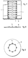
Bei der Ausführung nach Fig. 1 besteht das ringförmige Filterelement, von dem nur ein stirnseitiger Endbereich gezeigt ist, aus einer sternförmig gefalteten Filterbahn 1 aus Papier mit geringen Anteilen an thermoplastischem Kunststoff. Im Filterelementinneren befindet sich eine durch das gesamte Filterelement axial hindurchgehende rohrförmige Einlage 2 aus Kunststoff. Diese Einlage 2 stellt eine sogenannte Kunststoffinnenzarge des Filterelementes dar.In the embodiment according to FIG. 1, the ring-shaped filter element, of which only an end area is shown, consists of a
Gedichtet ist die Stirnseite des Filterelementes durch ein Vlies 3 aus Polyester, wobei dieses Polyester vorzugsweise ein Polyethylenterephtalat ist. Verbunden ist dieses Vlies mit den Stirnkanten der Filterbahn durch an sich bekanntes Ultraschallschweißen. Das Vliesmaterial ragt radial innen über die rohrförmige Einlage 2 hinaus.The end face of the filter element is sealed by a
Über das Vlies 3 als Zwischenlage ist auf die Stirnkante der rohrförmigen Einlage 2 ein Kunststoffring 4 mittels Ultraschall aufgeschweißt. Dieser Kunststoffring 4 hat im Schnitt eine L-Form. Dieser Ring dient dazu, ein radial außen liegendes Widerlager für den radial innen liegenden Teil des Vlieses 3 zu bilden, wenn das Filterelement in Richtung des Pfeiles A auf ein Rohr aufgesteckt wird.A plastic ring 4 is welded onto the end edge of the
Während die Fig. 1 eine Ausführung zeigt, bei der das Filterelement in Richtung des Pfeiles A auf ein durchgehendes Rohrstück aufgeschoben werden muß, zeigt die Fig. 2 eine Ausführung, bei der die Aufschieberichtung für das Filterelement gleichgültig ist. Denn dort ist auch der an den Kunststoffring 4 angrenzende Endbereich der rohrförmigen Einlage 2 so ausgebildet, daß der radial innen überragende Teil des Vlieses 3 dort kammerartig zwischen der Einlage 2 und dem Rohr, auf das das Filterelement aufgeschoben ist, verpreßbar ist, wie es in EP 0 559 011 A1 beschrieben ist.1 shows an embodiment in which the filter element has to be pushed onto a continuous piece of pipe in the direction of arrow A, FIG. 2 shows an embodiment in which the push-on direction for the filter element is indifferent. Because there is also the end region of the
Der bei der Ausführung nach Fig. 3 aufgeschweißte Kunststoffring 5 dient zur Aufnahme eines Dichtringes 6.The
Ebenfalls zur Aufnahme eines Dichtringes 7 dient der Kunststoffring 8 bei der Ausführung nach Fig. 4.The
Auch bei der Ausführung nach Fig. 5 dient ein etwas anders gestalteter Kunststoffring 9 wiederum zur Aufnahme eines Dichtringes 10. Eine weitere alternative Ausführungsform zeigt Fig. 6 mit einem Kunststoffring 11 und einem Dichtring 12.5 also serves a little differently designed plastic ring 9 in turn for receiving a sealing
Nach Fig. 7 ist eine Deckscheibe 13 aus festem kompaktem Material über das Vlies 3 als Zwischenlage auf der Stirnkante der rohrförmigen Einlage 2 ultraschallmäßig aufgeschweißt. Der radial innen überragende Teil des Vlieses 3 dient in umgebogener Form wiederum in der weiter oben bereits mehrfach beschriebenen Form als radiale Dichtung.According to FIG. 7, a
In allen dargestellten Ausführungsbeispielen erfolgt das Ultraschall-Aufschweißen der Kunststoffringe 4, 5, 8, 9, 11 und der Deckscheibe 13 jeweils über angeformte Vorsprünge 14 (Fig. 8, 9). Die Höhe dieser Vorsprünge 14 ist derart gewählt, daß einerseits eine sichere Verschweißung an der rohrförmigen Einlage 2 gegeben ist und daß andererseits das zwischen den Vorsprüngen 14 liegende Vliesmaterial 3 ausreichend dicht verspannt, aber noch nicht verschweißt ist.In all of the illustrated exemplary embodiments, the ultrasonic welding of the plastic rings 4, 5, 8, 9, 11 and the
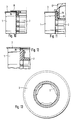
Bei der Ausführung nach Fig. 10 ist eine Deckplatte 15 auf das offene Ende eines Filterelementes fest aufgesetzt. Zu einem solchen festen Aufsetzen ist die Deckplatte 15 mit über ihren Umfang verteilten Dornen 16 versehen, die durch das Vlies 3 hindurch in entsprechende Aufnahmen in dem rohrförmigen Einlageteil 2 fest eingeklemmt sind. Die Rastverbindung ist derart ausgebildet, daß das Vlies 3 zwischen der Deckplatte 15 und der Stirnfläche der rohrförmigen Einlage 2 dicht verspannt ist, so daß die Deckplatte das Filterelement an dem betreffenden Ende dicht abschließt. Anstelle der Deckplatte können auch andere Funktionsträgerteile in der gleichen Weise an der rohrförmigen Einlage 2 des Filterelementes angebracht werden. Hierdurch ist ein Ersatz für eine Schweißverbindung nach den vorhergehenden Ausführungsbeispielen gegeben.10, a cover plate 15 is firmly placed on the open end of a filter element. For such a fixed placement, the cover plate 15 is provided with
Bei dem Filterelement nach Fig. 11 ist ein Stöpsel 17 durch das offene Ende eines Filterelementes in das Innere des rohrförmigen Einlageteiles 2 über federnde Füße 18 eingeschnappt. Auch bei dieser Ausführung ist mit dem Stöpsel 17 ein dichter Verschluß des offenen Endes des Filterelementes möglich. Die Dichtheit wird dadurch erzielt, daß ein radial innen über den Rand der rohrförmigen Einlage 2 hinausragender Randbereich des Vlieses 3 zu einer Radialdichtung zwischen dem Stöpsel 17 und der rohrförmigen Einlage 2 herangezogen wird. Zu diesem Zweck ist dieser überragende Rand des Vlieses in einen radialen Spalt 19 dicht eingepreßt. Wie bei der Ausführung nach Fig. 10 kann anstelle des eingeschnappten Verschluß-Stöpsels 17 auch ein beliebiger Funktionsträger zur Aufnahme irgendwelcher an dem Filterelement anzubringender Teile dienen.In the filter element according to FIG. 11, a
Ein Ausführungsbeispiel für einen äußerst einfach und damit kostengünstig zu erzielenden Verschluß eines offenen Endes eines Filterelementes ist in Fig. 12 gezeigt. Dort besitzt die rohrförmige Einlage 2 ein verschlossenes Ende. Das Vlies 3 ist gleichzeitig auf die Stirnkanten der Filterbahn 1 und die Stirnfläche der rohrförmigen Einlage 2 im Ultraschallverfahren aufgeschweißt. Die Materialien des Vlieses 3 und der rohrförmigen Einlage 2 enthalten jeweils zumindest thermoplastischen Kunststoff oder sind wie das Vlies 3 und die rohrförmige Einlage 2 vollständig aus einem solchen Material. Das Vlies 3 ist aus thermoplastischem Polyester. Das Material der Filterbahn 1 ist aus Papier und enthält geringe Anteile aus Kunststoffharzen.An embodiment of an extremely simple and therefore inexpensive closure of an open end of a filter element is shown in FIG. 12. There, the
Um bei einem gleichzeitigen Aufschweißen des Vlieses 3 im Ultraschallverfahren auf die Stirnkanten der Filterbahn 1 und der rohrförmigen Einlage 2 ein Abscheren des Vlieses 3 an dem Übergang zwischen Filterbahn 1 und rohrförmiger Einlage 2 zu vermeiden, ist an diesem Übergang ein Ringspalt 20 vorgesehen. Dieser Ringspalt sollte mindestens eine radiale Erstreckung von etwa 0,5mm besitzen.In order to prevent the
Eine weitere, insbesondere zusätzliche, Maßnahme zur Vermeidung eines Abscherens des Vlieses 3 an der radialen Außenkante der rohrförmigen Einlage 2 erfolgt durch die Verschweißung des Vlieses 3 auf dieser rohrförmigen Einlage 2 rasterförmig (Fig. 13). Rasterförmig soll hier bedeuten, daß keine vollflächige Verschweißung auf der Stirnfläche der Einlage 2 erfolgt, sondern vielmehr lediglich eine raster- bzw. netzartige Verschweißung in den Knotenpunkten oder Linien eines Flächennetzwerkes. Auf diese Weise bleiben jeweils elastische Bereiche an dem Vlies 3, die ein Abscheren an der radialen Außenkante der rohrförmigen Einlage 2 beim Übergang zu der Filterbahn 1 verhindern. Die rasterförmige Verschweißung wird durch die Verwendung einer Ultraschallschweiß-Sonotrode mit einer beispielsweise waffelartig rillierten Oberfläche erzielt.A further, in particular additional, measure to avoid shearing off the
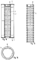
Das Filterelement nach Fig. 14 ist für den Einsatz in dem Ölfilter eines Verbrennungsmotors eines Kraftfahrzeuges bestimmt. Für diesen Anwendungsfall sind sämtliche beschriebenen Ausführungsbeispiele vorrangig geeignet und bestimmt.14 is intended for use in the oil filter of an internal combustion engine of a motor vehicle. For this application, all of the exemplary embodiments described are primarily suitable and determined.
Das Filterelement nach Fig. 14 soll insgesamt ausschließlich aus thermisch entsorgbarem Material bestehen.The filter element according to FIG. 14 should consist entirely of thermally disposable material.
Eine Besonderheit jenes Filterelementes besteht darin, daß es an einem Ende drehbar in ein Gehäuseteil einrastbar sein soll. An diesem Ende soll das Filterelement dicht verschlossen sein.A special feature of that filter element is that it should be rotatable at one end in a housing part. The filter element should be tightly closed at this end.
An dem anderen axialen Ende des Filterelementes soll das Filterelement radial dicht auf einen von dem Filtergehäuse ausgehenden Stutzen aufsteckbar sein. Bei in einem Filtergehäuse eingesetzten Zustand soll das Filterelement radial durchströmt werden.At the other axial end of the filter element, the filter element should be able to be plugged radially tight onto a connecting piece extending from the filter housing. When inserted in a filter housing, the filter element is to be flowed through radially.
Zur Erzielung des drehbaren Rastverschlusses des Filterelementes gegenüber dem Filtergehäuse ist die rohrförmige Einlage 2 an ihrem einen Ende mit einem entsprechenden topfförmigen Verschluß mit nach innen gezogenen Kragenabschnitten 21 (Fig. 15, 16) versehen. Über diese Abschnitte ist eine Verrasterung an einem ringförmigen Gegenhalter des Filtergehäuses möglich. Die bei einem Filterelement dieser Art übliche Bezeichnung für die rohrförmige Einlage 2 ist "Kunststoffinnenzarge".In order to achieve the rotatable locking closure of the filter element with respect to the filter housing, the
An dem topfförmig ausgebildeten Ende der Einlageteiles 2 ist ein ringförmiges Vlies 3 in der nach Fig. 12 beschriebenen Weise im Ultraschallverfahren gleichzeitig auf die Stirnkanten des Filterbahnmaterials und die Stirnringfläche der Einlage 2 aufgeschweißt.At the cup-shaped end of the
An dem anderen Ende des Filterelementes erfolgt die Dichtung gegenüber dem Stutzen, auf das das Filterelement aufzustecken ist, durch eine Radialdichtung, die von einem umgeklappten Innenbereich des Vlieses 3 an diesem Ende in an sich bekannter Weise gebildet wird. Auf dieses Ende des Ringfilters ist im Ultraschallverfahren eine ringförmige Deckscheibe 13 aufgebracht. Die Art des Aufbringens entspricht derjenigen, die im Zusammenhang mit den Figuren 8 und 9 näher beschrieben ist. Die Deckscheibe 13 dient bei diesem Filterelement dazu, dieses über die Deckscheibe axial an ein Ventil anlegen zu können. Ohne eine solche feste Deckscheibe bestünde die Gefahr einer Zerstörung des aufgeschweißten Vlieses 3 an diesem Ende des Filterelementes. Durch die Verwendung von Vliesendscheiben ist eine besonders kostengünstige Herstellung eines solchen Filterelementes möglich.At the other end of the filter element, the seal with respect to the connection piece onto which the filter element is to be placed is made by a radial seal which is formed at this end in a manner known per se by a folded inner region of the
Claims (14)
dadurch gekennzeichnet,
daß ein Zusatzteil (4, 5, 8, 9, 11, 13) aus kompaktem, im wesentlichen starrem Material, das zumindest Anteile an thermoplastischem Kunststoff enthält, über das Vlies (3) als Zwischenschicht mit der rohrförmigen Einlage (2) verschweißt ist.Ring filter element made of a filter material arranged in a ring, in particular a zigzag-folded filter web material, with a non-woven cover made of at least partially thermoplastic material which is tightly applied to at least one of the end faces by ultrasonic welding and which in its radial inner region has the end ring surface of a tubular insert provided in the center of the ring filter, especially a plastic inner frame, covered,
characterized by
that an additional part (4, 5, 8, 9, 11, 13) made of compact, essentially rigid material, which contains at least portions of thermoplastic, is welded to the tubular insert (2) as an intermediate layer via the fleece (3).
dadurch gekennzeichnet,
daß die Verschweißung eine Ultraschallverschweißung ist.Ring filter element according to claim 1,
characterized by
that the weld is an ultrasonic weld.
dadurch gekennzeichnet,
daß das angeschweißte Zusatzteil (4, 5, 8, 9, 11, 13) lokale der Stirnfläche der rohrförmigen Einlage (2) zugeordnete noppenartige Vorsprünge (14) besitzt und daß die Schweißverbindung gegenüber der rohrförmigen Einlage (2) allein über diese Vorsprünge (14) gegeben ist, während das Vlies (3) in den umfangsmäßig zwischen den Vorsprüngen (14) liegenden Bereichen dicht zwischen dem aufgeschweißten Zusatzteil (4, 5, 8, 9, 11, 13) und der Stirnfläche der rohrförmigen Einlage (2) verpreßt ist.Ring filter element according to claim 1 or 2,
characterized by
that the welded-on additional part (4, 5, 8, 9, 11, 13) is assigned locally to the end face of the tubular insert (2) has nub-like projections (14) and that the welded connection to the tubular insert (2) is provided solely via these projections (14), while the fleece (3) in the areas lying circumferentially between the projections (14) is tight between the welded-on additional part ( 4, 5, 8, 9, 11, 13) and the end face of the tubular insert (2) is pressed.
dadurch gekennzeichnet,
daß das aufgeschweißte Zusatzteil eine Ringscheibe (13) ist.Ring filter element according to one of the preceding claims,
characterized by
that the welded-on additional part is an annular disc (13).
dadurch gekennzeichnet,
daß das aufgeschweißte Zusatzteil ein Ring (4) mit einem Innendurchmesser ist, der so bemessen ist, daß ein radial nach innen überragender Rand des Vlieses (3) durch Anlage an den Innenumfang dieses Ringes (4) als Dichtung gegenüber einem in diesen Ring (4) eingeführten zylindrischen Teil wirken kann.Ring filter element according to one of claims 1 to 3,
characterized by
that the welded-on additional part is a ring (4) with an inner diameter which is dimensioned such that a radially inwardly projecting edge of the fleece (3) by contacting the inner circumference of this ring (4) as a seal with respect to one in this ring (4 ) inserted cylindrical part can act.
dadurch gekennzeichnet,
daß das aufgeschweißte Zusatzteil (5, 8, 9, 11) ein Träger für radiale oder axial wirkende Endscheibendichtungen des Filterelementes ist.Ring filter element according to one of claims 1 to 3,
characterized by
that the welded additional part (5, 8, 9, 11) is a carrier for radial or axially acting end plate seals of the filter element.
dadurch gekennzeichnet,
daß von axial außen ein Zusatzteil (15) auf der Vliesabdeckung aufliegt, das über von diesem abstehende Dorne (16) durch das Vlies (3) hindurch mit der rohrförmigen Einlage (2) verrastet bzw. in diese eingeklemmt ist.Ring filter element according to the preamble of claim 1,
characterized by
that from the outside axially an additional part (15) on the fleece cover rests, which is locked or clamped into the tubular insert (2) by means of the spikes (16) projecting therefrom through the fleece (3).
dadurch gekennzeichnet,
daß dieses Zusatzteil (15) eine Ringscheibe ist.Ring filter element according to claim 7,
characterized by
that this additional part (15) is an annular disc.
dadurch gekennzeichnet,
daß durch mindestens eines der offenen Enden des Filterelementes ein Zusatzteil (17) in den Innenumfang der rohrförmigen Einlage (2) eingerastet bzw. eingeklemmt ist, und daß dieses Zusatzteil (17) zumindest einen zylindrischen Außenbereich besitzt, der zusammen mit einem radial zugeordneten ebenfalls zylindrischen Bereich der rohrförmigen Einlage (2) einen axial begrenzten Ringspalt (19) bildet, in dem der Innenrand des Vlieses (3) dicht einklemmbar ist.Ring filter element according to the preamble of claim 1,
characterized by
that by at least one of the open ends of the filter element, an additional part (17) is latched or clamped into the inner circumference of the tubular insert (2), and that this additional part (17) has at least one cylindrical outer region, which together with a radially assigned, likewise cylindrical Area of the tubular insert (2) forms an axially limited annular gap (19) in which the inner edge of the fleece (3) can be tightly clamped.
dadurch gekennzeichnet,
daß das eingerastete Zusatzteil (15, 17) das betreffende offene Ende des Filterelementes dicht verschließt.Ring filter element according to claim 7 or 9,
characterized by
that the latched additional part (15, 17) tightly closes the open end of the filter element in question.
dadurch gekennzeichnet,
daß das eingerastete Zusatzteil (15, 17) für eine Rast- bzw. Schnappanbindung des Filterelementes an ein das Filterelement umschließendes Gehäuseteil ausgebildet ist.Ring filter element according to claim 9 or 10,
characterized by
that the latched additional part (15, 17) is designed for a snap or snap connection of the filter element to a housing part enclosing the filter element.
dadurch gekennzeichnet,
daß die Vliesabdeckung (3) gleichzeitig mit den Stirnkanten bzw. Flächen des Filterbahnmaterials (1) und der rohrförmigen Einlage (2) ultraschallverschweißt ist, und daß zwischen der Stirnfläche der rohrförmigen Einlage (2) und dem Innenumfang der Stirnkanten des Materials der Filterbahn (1) ein axial begrenzter Ringspalt (20) vorgesehen ist.Ring filter element according to the preamble of claim 1,
characterized by
that the fleece cover (3) is simultaneously ultrasonically welded to the end edges or surfaces of the filter web material (1) and the tubular insert (2), and that between the end surface of the tubular insert (2) and the inner circumference of the end edges of the material of the filter web (1 ) an axially limited annular gap (20) is provided.
dadurch gekennzeichnet,
daß die radiale Erstreckung des Ringspaltes (20) mindestens etwa O,5mm beträgt.Ring filter element according to claim 12,
characterized by
that the radial extent of the annular gap (20) is at least about 0.5 mm.
dadurch gekennzeichnet,
daß die Vliesabdeckung (3) mit der Stirnringfläche der rohrförmigen Einlage (2) rastermäßig verschweißt ist.Ring filter element according to claim 12 or 13,
characterized by
that the fleece cover (3) is welded in a grid pattern to the end face of the tubular insert (2).
Applications Claiming Priority (2)
| Application Number | Priority Date | Filing Date | Title |
|---|---|---|---|
| DE4419361A DE4419361A1 (en) | 1994-06-03 | 1994-06-03 | Ring filter element with fleece cover on the front |
| DE4419361 | 1994-06-03 |
Publications (2)
| Publication Number | Publication Date |
|---|---|
| EP0685251A1 true EP0685251A1 (en) | 1995-12-06 |
| EP0685251B1 EP0685251B1 (en) | 1998-08-12 |
Family
ID=6519664
Family Applications (1)
| Application Number | Title | Priority Date | Filing Date |
|---|---|---|---|
| EP95106585A Expired - Lifetime EP0685251B1 (en) | 1994-06-03 | 1995-05-02 | Ring filter element having a front covering of non woven fabric |
Country Status (3)
| Country | Link |
|---|---|
| EP (1) | EP0685251B1 (en) |
| DE (2) | DE4419361A1 (en) |
| ES (1) | ES2120658T3 (en) |
Cited By (13)
| Publication number | Priority date | Publication date | Assignee | Title |
|---|---|---|---|---|
| EP0781586A3 (en) * | 1995-12-27 | 1997-07-09 | Knecht Filterwerke Gmbh | Ring filter insert |
| WO1998005403A1 (en) * | 1996-08-02 | 1998-02-12 | Filterwerk Mann+Hummel Gmbh | Snap-on central pipe |
| EP0826566A2 (en) * | 1996-08-28 | 1998-03-04 | Autoliv ASP, Inc. | Integral label/gasket for crimped inflator housing |
| WO2000000263A1 (en) * | 1998-06-26 | 2000-01-06 | Pall Corporation | Filter element and method of making a filter element |
| WO2000018489A1 (en) * | 1998-09-30 | 2000-04-06 | Mahle Filtersysteme Gmbh | Plate filter element for an air filter |
| EP1163945A1 (en) | 2000-06-17 | 2001-12-19 | Filterwerk Mann + Hummel Gmbh | Cylindrical filter cartridge with supporting tube |
| US6739459B1 (en) | 1998-06-26 | 2004-05-25 | Pall Corporation | Filter element including bonded end caps and support core |
| EP1424118A1 (en) * | 2002-11-29 | 2004-06-02 | Mann+Hummel Gmbh | Liquid filter element |
| DE102013017302A1 (en) * | 2013-10-18 | 2015-04-23 | Mann + Hummel Gmbh | A filter assembly |
| DE10259900B4 (en) | 2002-12-20 | 2018-03-08 | Mann + Hummel Gmbh | Filter element, method for its manufacture and use of the filter element |
| EP3530337A1 (en) * | 2018-02-27 | 2019-08-28 | Mahle Metal Leve S/A | Fuel pre-filtering element |
| WO2021021655A1 (en) * | 2019-07-26 | 2021-02-04 | Donaldson Company, Inc. | Filter elements and methods of manufacturing filter elements |
| CN116379016A (en) * | 2022-12-01 | 2023-07-04 | 鹤山市民强五金机电有限公司 | Ventilation fan with clearance filter component function |
Families Citing this family (9)
| Publication number | Priority date | Publication date | Assignee | Title |
|---|---|---|---|---|
| DE19541385A1 (en) * | 1995-11-07 | 1997-05-15 | Knecht Filterwerke Gmbh | Radially flowable ring filter element |
| DE19723580A1 (en) * | 1997-06-05 | 1998-12-10 | Knecht Filterwerke Gmbh | Filters for gases and liquids |
| DE19727369A1 (en) * | 1997-06-27 | 1999-01-07 | Knecht Filterwerke Gmbh | Tubular filter element |
| WO1999019043A2 (en) * | 1997-10-09 | 1999-04-22 | Pall Corporation | Filter elements and methods for making filter elements |
| DE10152552A1 (en) * | 2001-10-24 | 2003-05-08 | Mann & Hummel Filter | Filter element, in particular for the filtration of liquids |
| DE102004025811A1 (en) | 2004-05-05 | 2006-03-23 | Mann + Hummel Gmbh | Filter element and liquid filter for freeze-endangered fluids and method for producing the filter element |
| DE102013011086A1 (en) | 2013-07-03 | 2015-01-08 | Mann + Hummel Gmbh | Filter element and method for producing a filter element |
| DE202019105409U1 (en) | 2019-09-30 | 2019-11-13 | Mahle International Gmbh | Ring filter element |
| DE102020121340B4 (en) | 2020-08-13 | 2023-10-26 | Mann+Hummel Gmbh | Filter element and filter device |
Citations (3)
| Publication number | Priority date | Publication date | Assignee | Title |
|---|---|---|---|---|
| DE3837423A1 (en) * | 1988-11-04 | 1990-05-10 | Bosch Gmbh Robert | LIQUID FILTER |
| DE4009246A1 (en) * | 1990-03-22 | 1991-09-26 | Knecht Filterwerke Gmbh | FILTER ELEMENT MADE OF A ZIGZAG-FOLDED, STAR- OR PLATE-SHAPED FILTER MATERIAL |
| EP0559011A1 (en) * | 1992-03-02 | 1993-09-08 | Knecht Filterwerke Gmbh | Ring filter element with the endwalls covered tightly by a sealing material in flat or film-like disposition |
Family Cites Families (13)
| Publication number | Priority date | Publication date | Assignee | Title |
|---|---|---|---|---|
| BE495750A (en) * | 1949-05-20 | |||
| DE1767427U (en) * | 1957-05-29 | 1958-05-29 | Mann & Hummel Filter | REPLACEABLE FILTER CARTRIDGE. |
| DE1924827U (en) * | 1965-07-30 | 1965-10-07 | Purolator Filter Gmbh | BULB ON HOUSING COVER FOR OIL FILTER. |
| US3382984A (en) * | 1965-10-04 | 1968-05-14 | Kuss & Co R L | Filter construction |
| CA1080130A (en) * | 1976-03-30 | 1980-06-24 | Pall Corporation | Pharmaceutical filter |
| US4301012A (en) * | 1979-04-25 | 1981-11-17 | Purolator Technologies, Inc. | Welded stainless steel mesh cleanable filter |
| US4218324A (en) * | 1979-05-03 | 1980-08-19 | Textron, Inc. | Filter element having removable filter media member |
| US4464263A (en) * | 1980-09-02 | 1984-08-07 | Fram Corporation | Pleated filter element and integral shield and method for making same |
| GB8411912D0 (en) * | 1984-05-10 | 1984-06-13 | Vokes Ltd | Filters |
| DE3429634A1 (en) * | 1984-08-11 | 1986-02-20 | Ing. Walter Hengst GmbH & Co KG, 4400 Münster | Screw-in filter for fuels and/or lubricants |
| EP0217482A1 (en) * | 1985-07-19 | 1987-04-08 | Hr Textron Inc. | Filter element |
| EP0498757B2 (en) * | 1991-02-08 | 1997-11-05 | Knecht Filterwerke Gmbh | Process for making an annular filter from a filter material folded into a star shape configuration |
| DE4206519C2 (en) * | 1992-03-02 | 1998-07-02 | Knecht Filterwerke Gmbh | Ring filter element with plate or foil-shaped sealing material that covers the end faces tightly |
-
1994
- 1994-06-03 DE DE4419361A patent/DE4419361A1/en not_active Withdrawn
-
1995
- 1995-05-02 EP EP95106585A patent/EP0685251B1/en not_active Expired - Lifetime
- 1995-05-02 DE DE59503123T patent/DE59503123D1/en not_active Expired - Lifetime
- 1995-05-02 ES ES95106585T patent/ES2120658T3/en not_active Expired - Lifetime
Patent Citations (3)
| Publication number | Priority date | Publication date | Assignee | Title |
|---|---|---|---|---|
| DE3837423A1 (en) * | 1988-11-04 | 1990-05-10 | Bosch Gmbh Robert | LIQUID FILTER |
| DE4009246A1 (en) * | 1990-03-22 | 1991-09-26 | Knecht Filterwerke Gmbh | FILTER ELEMENT MADE OF A ZIGZAG-FOLDED, STAR- OR PLATE-SHAPED FILTER MATERIAL |
| EP0559011A1 (en) * | 1992-03-02 | 1993-09-08 | Knecht Filterwerke Gmbh | Ring filter element with the endwalls covered tightly by a sealing material in flat or film-like disposition |
Cited By (20)
| Publication number | Priority date | Publication date | Assignee | Title |
|---|---|---|---|---|
| EP0781586A3 (en) * | 1995-12-27 | 1997-07-09 | Knecht Filterwerke Gmbh | Ring filter insert |
| WO1998005403A1 (en) * | 1996-08-02 | 1998-02-12 | Filterwerk Mann+Hummel Gmbh | Snap-on central pipe |
| EP0826566A2 (en) * | 1996-08-28 | 1998-03-04 | Autoliv ASP, Inc. | Integral label/gasket for crimped inflator housing |
| EP0826566A3 (en) * | 1996-08-28 | 2000-02-02 | Autoliv ASP, Inc. | Integral label/gasket for crimped inflator housing |
| US6739459B1 (en) | 1998-06-26 | 2004-05-25 | Pall Corporation | Filter element including bonded end caps and support core |
| WO2000000263A1 (en) * | 1998-06-26 | 2000-01-06 | Pall Corporation | Filter element and method of making a filter element |
| WO2000018489A1 (en) * | 1998-09-30 | 2000-04-06 | Mahle Filtersysteme Gmbh | Plate filter element for an air filter |
| US6379438B1 (en) | 1998-09-30 | 2002-04-30 | Mahle Filtersysteme Gmbh | Plate filter element for an air filter |
| EP1163945B1 (en) * | 2000-06-17 | 2009-04-29 | Mann + Hummel GmbH | Cylindrical filter cartridge with supporting tube |
| EP1163945A1 (en) | 2000-06-17 | 2001-12-19 | Filterwerk Mann + Hummel Gmbh | Cylindrical filter cartridge with supporting tube |
| EP1424118A1 (en) * | 2002-11-29 | 2004-06-02 | Mann+Hummel Gmbh | Liquid filter element |
| EP1424118B1 (en) | 2002-11-29 | 2016-04-27 | MANN+HUMMEL GmbH | Liquid filter element |
| DE10259900B4 (en) | 2002-12-20 | 2018-03-08 | Mann + Hummel Gmbh | Filter element, method for its manufacture and use of the filter element |
| DE102013017302A1 (en) * | 2013-10-18 | 2015-04-23 | Mann + Hummel Gmbh | A filter assembly |
| DE102013017302B4 (en) | 2013-10-18 | 2019-03-14 | Mann+Hummel Gmbh | A filter assembly |
| EP3530337A1 (en) * | 2018-02-27 | 2019-08-28 | Mahle Metal Leve S/A | Fuel pre-filtering element |
| US11007459B2 (en) | 2018-02-27 | 2021-05-18 | Mahle International Gmbh | Fuel pre-filtering element |
| WO2021021655A1 (en) * | 2019-07-26 | 2021-02-04 | Donaldson Company, Inc. | Filter elements and methods of manufacturing filter elements |
| CN114555209A (en) * | 2019-07-26 | 2022-05-27 | 唐纳森公司 | Filter element and method for producing a filter element |
| CN116379016A (en) * | 2022-12-01 | 2023-07-04 | 鹤山市民强五金机电有限公司 | Ventilation fan with clearance filter component function |
Also Published As
| Publication number | Publication date |
|---|---|
| DE59503123D1 (en) | 1998-09-17 |
| EP0685251B1 (en) | 1998-08-12 |
| ES2120658T3 (en) | 1998-11-01 |
| DE4419361A1 (en) | 1995-12-07 |
Similar Documents
| Publication | Publication Date | Title |
|---|---|---|
| EP0685251B1 (en) | Ring filter element having a front covering of non woven fabric | |
| EP0912225B1 (en) | Disk, in particular the front disk of a filter element | |
| EP0897317B1 (en) | End disc for an annular filter element with a seal which acts radially | |
| DE69201671T2 (en) | Sealing attachments for filter elements. | |
| DE69503477T2 (en) | MEMBRANE SUPPORT AND SEALING DEVICE | |
| EP0559011B1 (en) | Ring filter element with the endwalls covered tightly by a sealing material in flat or film-like disposition | |
| DE60133449T2 (en) | Fluid filter and a fluid filter filter head device | |
| DE4416577C2 (en) | Filter insert for a filter for filtering liquid or gaseous media | |
| EP0650751A2 (en) | Filter apparatus | |
| EP0450299A1 (en) | Filtering element with folded material in ring or flat disposition | |
| EP0773052B1 (en) | Radially traversed ring filter element | |
| WO2007085427A1 (en) | Filter element with connecting element | |
| EP1137473A1 (en) | Filter cartridge arrangement | |
| DE4206519C2 (en) | Ring filter element with plate or foil-shaped sealing material that covers the end faces tightly | |
| EP0317903A1 (en) | Sealing ring | |
| DE3000013A1 (en) | LIQUID FILTER | |
| DE102014000597A1 (en) | liquid filters | |
| DE4419360C1 (en) | Ring-shaped filter | |
| DE19850423C2 (en) | ball joint | |
| DE4225144A1 (en) | Ring filter | |
| EP0528179B1 (en) | Liquid filter | |
| DE19731766B4 (en) | Flat plate filter made of zig-zag folded filter web material and flat filter housing with such a plate filter | |
| DE19527843B4 (en) | Oil or fuel filter device of an internal combustion engine | |
| DE10354315A1 (en) | Filter element for filtering liquid and gaseous media has an elastic mass arranged on the inner periphery of the filter medium in the region of the end plate | |
| EP4081324B1 (en) | Filter element |
Legal Events
| Date | Code | Title | Description |
|---|---|---|---|
| PUAI | Public reference made under article 153(3) epc to a published international application that has entered the european phase |
Free format text: ORIGINAL CODE: 0009012 |
|
| 17P | Request for examination filed |
Effective date: 19950929 |
|
| AK | Designated contracting states |
Kind code of ref document: A1 Designated state(s): DE ES FR GB IT |
|
| 17Q | First examination report despatched |
Effective date: 19961216 |
|
| GRAG | Despatch of communication of intention to grant |
Free format text: ORIGINAL CODE: EPIDOS AGRA |
|
| GRAG | Despatch of communication of intention to grant |
Free format text: ORIGINAL CODE: EPIDOS AGRA |
|
| GRAH | Despatch of communication of intention to grant a patent |
Free format text: ORIGINAL CODE: EPIDOS IGRA |
|
| GRAH | Despatch of communication of intention to grant a patent |
Free format text: ORIGINAL CODE: EPIDOS IGRA |
|
| GRAA | (expected) grant |
Free format text: ORIGINAL CODE: 0009210 |
|
| AK | Designated contracting states |
Kind code of ref document: B1 Designated state(s): DE ES FR GB IT |
|
| PG25 | Lapsed in a contracting state [announced via postgrant information from national office to epo] |
Ref country code: IT Free format text: LAPSE BECAUSE OF FAILURE TO SUBMIT A TRANSLATION OF THE DESCRIPTION OR TO PAY THE FEE WITHIN THE PRE;WARNING: LAPSES OF ITALIAN PATENTS WITH EFFECTIVE DATE BEFORE 2007 MAY HAVE OCCURRED AT ANY TIME BEFORE 2007. THE CORRECT EFFECTIVE DATE MAY BE DIFFERENT FROM THE ONE RECORDED.SCRIBED TIME-LIMIT Effective date: 19980812 |
|
| REF | Corresponds to: |
Ref document number: 59503123 Country of ref document: DE Date of ref document: 19980917 |
|
| GBT | Gb: translation of ep patent filed (gb section 77(6)(a)/1977) |
Effective date: 19980828 |
|
| REG | Reference to a national code |
Ref country code: ES Ref legal event code: FG2A Ref document number: 2120658 Country of ref document: ES Kind code of ref document: T3 |
|
| ET | Fr: translation filed | ||
| PLBE | No opposition filed within time limit |
Free format text: ORIGINAL CODE: 0009261 |
|
| STAA | Information on the status of an ep patent application or granted ep patent |
Free format text: STATUS: NO OPPOSITION FILED WITHIN TIME LIMIT |
|
| 26N | No opposition filed | ||
| REG | Reference to a national code |
Ref country code: GB Ref legal event code: IF02 |
|
| PGFP | Annual fee paid to national office [announced via postgrant information from national office to epo] |
Ref country code: GB Payment date: 20140530 Year of fee payment: 20 |
|
| PGFP | Annual fee paid to national office [announced via postgrant information from national office to epo] |
Ref country code: ES Payment date: 20140623 Year of fee payment: 20 |
|
| PGFP | Annual fee paid to national office [announced via postgrant information from national office to epo] |
Ref country code: DE Payment date: 20140731 Year of fee payment: 20 |
|
| PGFP | Annual fee paid to national office [announced via postgrant information from national office to epo] |
Ref country code: FR Payment date: 20140528 Year of fee payment: 20 |
|
| REG | Reference to a national code |
Ref country code: DE Ref legal event code: R071 Ref document number: 59503123 Country of ref document: DE |
|
| REG | Reference to a national code |
Ref country code: GB Ref legal event code: PE20 Expiry date: 20150501 |
|
| REG | Reference to a national code |
Ref country code: ES Ref legal event code: FD2A Effective date: 20150724 |
|
| PG25 | Lapsed in a contracting state [announced via postgrant information from national office to epo] |
Ref country code: GB Free format text: LAPSE BECAUSE OF EXPIRATION OF PROTECTION Effective date: 20150501 |
|
| PG25 | Lapsed in a contracting state [announced via postgrant information from national office to epo] |
Ref country code: ES Free format text: LAPSE BECAUSE OF EXPIRATION OF PROTECTION Effective date: 20150503 |