EP0683542B1 - Omnidirectional slot antenna - Google Patents
Omnidirectional slot antenna Download PDFInfo
- Publication number
- EP0683542B1 EP0683542B1 EP94308457A EP94308457A EP0683542B1 EP 0683542 B1 EP0683542 B1 EP 0683542B1 EP 94308457 A EP94308457 A EP 94308457A EP 94308457 A EP94308457 A EP 94308457A EP 0683542 B1 EP0683542 B1 EP 0683542B1
- Authority
- EP
- European Patent Office
- Prior art keywords
- radiation
- radiation slots
- antenna apparatus
- conductive plates
- slots
- Prior art date
- Legal status (The legal status is an assumption and is not a legal conclusion. Google has not performed a legal analysis and makes no representation as to the accuracy of the status listed.)
- Expired - Lifetime
Links
Images


Classifications
-
- H—ELECTRICITY
- H01—ELECTRIC ELEMENTS
- H01Q—ANTENNAS, i.e. RADIO AERIALS
- H01Q21/00—Antenna arrays or systems
- H01Q21/06—Arrays of individually energised antenna units similarly polarised and spaced apart
- H01Q21/20—Arrays of individually energised antenna units similarly polarised and spaced apart the units being spaced along or adjacent to a curvilinear path
- H01Q21/205—Arrays of individually energised antenna units similarly polarised and spaced apart the units being spaced along or adjacent to a curvilinear path providing an omnidirectional coverage
-
- H—ELECTRICITY
- H01—ELECTRIC ELEMENTS
- H01Q—ANTENNAS, i.e. RADIO AERIALS
- H01Q13/00—Waveguide horns or mouths; Slot antennas; Leaky-waveguide antennas; Equivalent structures causing radiation along the transmission path of a guided wave
- H01Q13/10—Resonant slot antennas
-
- H—ELECTRICITY
- H01—ELECTRIC ELEMENTS
- H01Q—ANTENNAS, i.e. RADIO AERIALS
- H01Q13/00—Waveguide horns or mouths; Slot antennas; Leaky-waveguide antennas; Equivalent structures causing radiation along the transmission path of a guided wave
- H01Q13/10—Resonant slot antennas
- H01Q13/12—Longitudinally slotted cylinder antennas; Equivalent structures
Definitions
- the present invention relates to a horizontally polarized antenna apparatus which has an omnidirectional pattern in the horizontal plane.
- Figs. 1(a) and 1(b) schematically illustrate a configuration of a horizontal polarized antenna apparatus which has an omnidirectional pattern in the horizontal plane explained in Chapter 12 of "VHF Antenna” written by Uchida and Mushiake, and issued by the Production Technology Center (March, 1977).
- Fig. 1(a) is a perspective view and Fig. 1(b) is a top plan view with electric field distribution indicated by arrows.
- the numeral 50 designates a dipole antenna and the symbol I indicates a current flowing through the dipole.
- a grounded conductor 51 includes four surfaces and a dipole antenna 50 is arranged at each surface.
- the dipole antenna 50 is arranged in parallel to the horizontal surface to excite a horizontally polarized wave.
- a plurality of dipole antennas may be arranged in the vertical direction. Amplitudes of currents flowing through the dipole antennas in the same height are equal, but phases thereof are sequentially different by 90 degrees.
- a dipole antenna 50 has a figure of-8 type radiation directivity, but substantially horizontally polarized omnidirectivity can be obtained through a combination of the four dipole elements.
- Figs. 2(a) - 2(c) show a conventional slot antenna indicated in "X-band omnidirectional double-slot array antenna" by T. Takeshima, ELECTRONIC ENGINEERING, No. 39, pp. 617-621 (October, 1967).
- FIG. 2(a) is a perspective view
- Fig. 2(b) is a sectional view along the line A-A
- Fig. 2(c) is a side elevation.
- numeral 60 designates a radiation slot; 61 a waveguide; and 62 a flange.
- Fig. 3(a) is a diagram illustrating a distribution of magnetic field inside the waveguide 61.
- Fig. 3(b) is a cross-sectional view along the line A-A illustrating a distribution of magnetic field inside the waveguide and a current flowing along the side surface.
- Electromagnetic waves propagated along the rectangular waveguide 61 excite the radiation slots 60 to radiate electromagnetic waves if the radiation slots 60 are provided in parallel with the waveguide axis at the positions offset from the center of the H plane of the rectangular waveguide 61.
- the radiation slots 60 are excited by providing each of the radiation slots 60 at a position where the magnetic field inside the waveguide 61 becomes maximum.
- An amount of electromagnetic wave radiation can be adjusted by changing the position of each radiation slot 60.
- the waveguide slot antenna shown in Figs. 2(a) - 2(c) may be used as a horizontally polarized omnidirectional antenna
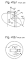
- the radiation slots 60 are provided, as shown in Fig. 4(a), on the front and rear H planes of the waveguide 61. Then, a distribution of electric field in the horizontal plane changes as shown in Fig. 4(b).
- the radiation slots 60 are excited out of phase and the radiation field becomes continuous in the horizontal plane. As a result, a theoretically omnidirectional directivity can be realized.
- two radiation slots can be excited in the same phase by arranging the radiation slots in symmetrical positions of the waveguide 61 with respect to the center thereof at an interval of ⁇ g/2 ( ⁇ g is a wavelength in the waveguide).
- the present invention has been proposed to overcome the problems described above and it is therefore an object of the present invention to provide a small-sized horizontally polarised omnidirectional antenna having a simplified configuration.
- US-A-4,247,858 discloses an antenna in accordance with the pre-characterising portion of claim 1 and which comprises a hollow body provided with radiation slots and filled with dielectric material.
- an antenna apparatus having radiation slots arranged at opposite positions on a grounded conductive rectangular hollow body formed of conductive plates, said hollow body being provided with a dielectric material therein, said radiation slots being excited out of phase to form an omnidirectional radiation pattern in a plane perpendicular to the longitudinal axis of said hollow body, characterised in that a through-hole is formed extending between said radiation slots and in that semi-cylindrical conductor plates are respectively mounted to the conductive plates parallel to the longitudinal axis of said hollow body for the purpose of reducing any influence of waves diffracted at the edges of the conductive plates.
- At least one conductive bar can be provided around the radiation slots to connect the opposing conductive plates, whereby any unwanted waveguide mode can be suppressed.
- the horn-type conductive plates enable a beam width in a plane including the longitudinal axis'to be reduced without changing the size and position of the radiation slots and an omni-directional high-gain radiation pattern to be achieved in the plane perpendicular to the longitudinal axis.
- the electrical field radiated from the radiation slots becomes continuous in a plane perpendicular to the hollow body, for instance, in the horizontal plane and therefore an omnidirectional radiation pattern can be obtained in the horizontal plane.
- the filling of the hollow body with a dielectric material means that the antenna apparatus can be manufactured in a small size due to a wavelength shortening effect of the dielectric material.
- the presence of the through-hole in the dielectric material between the radiation slots means that the radiation slots become longer to thereby resonate at the same frequency, a beam width becomes narrow in the plane perpendicular to the hollow body and a gain can be increased.
- Fig. 1(a) is a perspective view of a conventional omnidirectional antenna apparatus.
- Fig. 1(b) is a plan view of the antenna apparatus of Fig. 1(a), illustrating a distribution of electric field.
- Fig. 2(a) is a perspective view illustrating another conventional omnidirectional antenna apparatus.
- Fig. 2(b) is a cross-sectional view taken along the line A-A of Fig. 2(a).
- Fig. 2(c) is a side elevation of the antenna apparatus of Fig. 2(a).
- Fig. 3(a) illustrates a distribution of magnetic field in the antenna apparatus of Fig.2 (a).
- Fig 3(b) illustrates directions of current and magnetic field at the cross-sectional taken along the line A-A of Fig. 3(a).
- Fig. 4(a) is a diagram for explaining directivity of the antenna apparatus of Fig. 2(a).
- Fig. 4(b) illustrates a horizontal distribution of electric field established by the antenna apparatus of Fig. 4(a).
- Fig. 5(a) is a perspective view of an antenna apparatus.
- Fig. 5(b) is a cross-sectional view taken along the line A-A of Fig. 5(a).
- Fig. 5(c) is a cross-sectional view taken along the line B-B of Fig. 5(a).
- Fig. 6 is a diagram for explaining operations of the antenna apparatus of Fig. 5(a).
- Fig. 7 is a graph illustrating a gain in the azimuth direction of the antenna apparatus of Fig. 5(a).
- Fig. 8(a) is a perspective view of an embodiment of an antenna apparatus of the present invention.
- Fig. 8(b) is a cross-sectional view taken along the line A-A of Fig. 8(a).
- Fig. 8(c) is a cross-sectional view taken along the line B-B of Fig. 8(a).
- Fig. 9(a) is a perspective view of another antenna apparatus.
- Fig. 9(b) is a side elevation of the antenna apparatus of Fig. 9(a).
- Fig. 10(a) is a perspective view of another antenna apparatus.
- Fig. 10(b) is a cross-sectional view taken along the line A-A of Fig. 10(a).
- Fig. 10(c) is a side elevation of the antenna apparatus of Fig. 10(a).
- Fig. 11(a) is a perspective view of another antenna apparatus.
- Fig. 11(b) is a cross-sectional view taken along the line A-A of Fig. 11(a).
- Fig. 11(c) is a side elevation of the antenna apparatus of Fig. 11(a).
- Fig. 12(a) is a perspective view of another antenna apparatus.
- Fig. 12(b) is a cross-sectional view taken along the line A-A of Fig. 12(a).
- Fig. 12(c) is a side elevation of the antenna apparatus of Fig. 12(a).
- Fig. 13(a) is a perspective view of another antenna apparatus.
- Fig. 13(b) is a cross-sectional view taken along the line A-A of Fig. 13(a).
- Fig. 13 (c) is a side elevation of the antenna apparatus of Fig. 13(a).
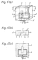
- Figs. 5(a) to 5(c) schematically illustrate a first antenna arrangement, Fig. 5(a) being a perspective view, Fig. 5(b) a cross-sectional view taken along the line A-A of Fig. 5(a) and Fig. 5(c) a cross-sectional view taken along the line B-B of Fig. 5(a).
- Fig. 5(a) being a perspective view
- Fig. 5(b) a cross-sectional view taken along the line A-A of Fig. 5(a)
- Fig. 5(c) a cross-sectional view taken along the line B-B of Fig. 5(a).
- radiation slots 1, 1' are formed respectively on a first set of parallel conductive plates 2, 2' and both conductive plates 2, 2' are connected by a second set of conductive plates 3', 3", 3''' to configurate a rectangular parallelepiped.
- the inside of the rectangular parallelepiped is filed with a dielectric material 4.
- the radiation slots 1, 1' are excited by a triplate line 6 formed of the conductive plates 2, 2' and strip lines 5.
- Numeral 7 designates a coaxial connector for feeding the triplate line; and 8 a coaxial line.
- the conductive plates 2, 2', 3, 3', 3", 3′′′ are grounded.
- Fig. 6 is a diagram explaining the principle of the antenna apparatus of Fig. 5(a).
- a signal propagating through the coaxial line 8 enters the triplate line 6 via the coaxial connector 7.
- the triplate line 6 can be formed in a small size resulting in reduction in size of the antenna apparatus by filling the rectangular parallelepiped with the dielectric material 4.
- Both ends of the triplate line 6 are connected respectively to the right side edge of the radiation slot 1 and the left side edge of the slot 1' with respect to Fig. 5(b) and a voltage is applied across the strip line 5 and the first set of the ground conductive plates 2, 2'. Since the ends of the triplate line 6 are connected to the opposite side edges of the radiation slots 1, 1', the electric fields inside the rectangular parallelepiped formed of the first set of conductive plates 2, 2' and the second set of conductive plates 3', 3", 3''' are reversed with each other as indicated by the arrow marks in Fig. 6.
- the radiation slots 1, 1' provided on the grounded conductive plates 2, 2' are excited out of phase (in a phase difference of 180 degrees).
- the radiation field formed by these radiation slots 1, 1' becomes continuous in the horizontal plane (azimuth direction) and a horizontally polarized omnidirectional radiation pattern can be obtained.
- Fig. 7 indicates measured gains of horizontally polarized and vertically polarized waves when the antenna apparatus of Fig. 5(a) is rotated 360 degrees in the horizontal plane.
- an amount of ripple is within 2 dB, resulting in a substantially omnidirectional pattern.
- the gain of the vertically polarized wave which is a cross-polarized wave is -20 db or less and satisfactory characteristics results.
- Figs. 8(a) to 8(c) schematically illustrate an antenna apparatus demonstrating one aspect of the present invention
- Fig. 8(a) being a perspective view
- Fig. 8(b) a cross-sectional view taken along the line A-A
- Fig. 8(c) a cross-sectional view taken along the line B-B.
- the antenna apparatus of this arrangement also shows, with the same principle as the antenna apparatus of Fig. 5, a horizontally polarized omnidirectional radiation pattern.
- the radiation slots 1, 1' Since the portion 9 of the dielectric material 4 between the radiation slots 1, 1' formed on the first set of grounded conductive plates 2, 2' is removed, the radiation slots 1, 1' must be longer, in order to have them resonate at the same resonance frequency that those in Fig. 5 wherein no dielectric material 4 is removed, because a wavelength shortening effect by the dielectric material 4 is lost.
- the radiation slots 1, 1' being set longer, the beam width becomes narrow, the gain in the direction perpendicular to the plates 2, 2' increases and the gain in the horizontal plane can be increased. It is noted that a dielectric material may be provided in a parallelepiped defined by the radiation slots 1, 1'.
- Figs. 9(a) and 9(b) schematically illustrate a further antenna arrangement, Fig. 9(a) being a perspective view and Fig. 9(b) a side elevation, in which horn-type metal conductors 15, 15' are optionally coupled to upper and lower surfaces of the antenna apparatus.
- this antenna employs the horn-type conductors 15, 15' coupled to the upper and lower ends of the antenna apparatus described before.
- the horn-type conductors 15, 15' operate in combination like a horn antenna. Since the gain of this antenna is determined by a size of the aperture of the horn, a higher gain can be obtained by enlarging the aperture of the horn.
- the beam width and gain in the vertical plane can be easily adjusted by changing the slant angle ⁇ .
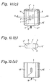
- Figs. 10(a) to 10(c) schematically illustrate an antenna demonstrating another aspect of the present invention, Fig. 10(a) being a perspective view, Fig. 10(b) a cross- section taken along the line A-A and Fig. 10(c) a side elevation.
- a third set of conductive plates 16, 16' is provided that electrically connect the first set of conductive plates 2, 2' of the antenna apparatus.
- an omnidirectional radiation pattern can be obtained if a size of the conductive plates 2, 2' is infinite. Since the conductive plates 2, 2' are limited in size, however, a ripple is generated due to the interference of waves diffracted at the edge portions of the conductive plates 2, 2'. The generated ripple changes in the period of about one wavelength depending on the size of the conductive plates 2, 2'.
- the conductive plates 16, 16' are additionally provided to cover the opposing conductive plates 3, 3" of the antenna apparatus.
- Figs. 11(a) to 11(c) schematically illustrate a configuration of a further antenna arrangement, Fig. 11(a) being a perspective view, Fig. 11(b) a cross-section taken along the line A-A and Fig. 11(c) a side elevation. This demonstrates the use of the horn-type conductors 15, 15a as in Figs. 9(a) and 9(b) together with conductive bars 18, 18'.
- the radiation slots 1, 1' are formed to oppose each other on a cylindrical waveguide 17 of which both ends are short-circuited. To one side edge of each of the radiation slots 1, 1' are soldered conductive bars 18, 18'. Numeral 19 designates a waveguide flange.
- a current flows in the axial direction. If the radiation slots 1, 1' are provided in parallel to the axis of the waveguide 17, the radiation slots 1, 1' are not excited because the slots do not cross the current.
- the radiation slots 1, 1' can be excited by fixing the conductive bars 18, 18' inside the circular waveguide 17 from the side edges of the radiation slots 1, 1'.
- a horizontally polarized omnidirectional radiation pattern can be obtained by arranging one or more radiation slots in the circumferential direction of the cylindrical waveguide 17.
- the beam width in the vertical plane can be narrowed by arranging a plurality of radiation slots in parallel to the longitudinal axis of the circular waveguide 17.
- the radiation slots 1, 1' are excited by exciting the cylindrical conductor 17, a standing wave position deviates when an excitation frequency of the waveguide 17 changes. Then, the amplitude and phase of a signal exciting the radiation slots 1, 1' change and a radiation pattern obtained by combining radiation fields from the slots 1, 1' also changes. It is possible to provide the horn-type conductors 15, 15' to both ends of the circular waveguide 17 in order to obtain a narrower beam width in the vertical plane.
- the radiation slots 1, 1' are excited using the conductor bars 18, 18', but it is possible to excite the radiation slots 1, 1' by slanting the radiation slots 1, 1' with respect to the axis of the circular waveguide 17.
- Figs. 12(a) to 12(c) schematically illustrate a configuration of a further antenna arrangement which has the conductive bars 18, 18', Fig. 12(a) being a perspective view, Fig. 12(b) a plan view taken along the line A-A and Fig. 12(c) a side elevation.
- a centre conductor 20 is provided through the circular waveguide 17 to form a coaxial line 17'. If the coaxial line 17' including short-circuited ends is excited in the basic mode (the magnetic field is uniform in the circumferential direction of the coaxial line 17'), a current flows in the longitudinal axial direction. If the radiation slots 1, 1' are provided in parallel to the axis of the coaxial line 17', the radiation slots 1, 1' are not excited.
- a horizontally polarized omnidirectional radiation pattern can be obtained by providing one or more radiation slots in the circumferential direction.
- a plurality of radiation slots may be arranged in parallel to the axis of the coaxial line 17'. Since the radiation slots 1, 1' are excited by exciting the coaxial line 17' the position of a standing wave is deviated if the excitation frequency of the coaxial line 17' is shifted. Then, the amplitude and phase of a signal for exciting the radiation slots 1, 1' change and a radiation pattern obtained by combining the radiation fields from the slots 1, 1' is also changed.
- the horn-type conductors 15, 15' may be provided, as described previously, to both ends of the coaxial line 17' in view of obtaining a narrower beam width in the vertical direction.
- Figs. 13(a) to 13(c) schematically illustrate a configuration of a further antenna arrangement with the conductive bars 18, 18', Fig. 13(a) being a perspective view, Fig. 13(b) a cross-sectional view taken along the line A-A and Fig. 13(c) a side elevation.
- the radiation slots 1, 1' are formed on two opposing surfaces of a rectangular waveguide 21. If the rectangular waveguide 21 having short-circuited ends is excited in the TE 01 mode, the radiation slots 1,1' must be formed at positions offset from the longitudinal axis of the waveguide 21 for excitation. Then, a beam tilt is generated like in the prior art and a ripple in the horizontal plane becomes large.
- the radiation slots 1, 1' are provided in parallel with the centre line of the H plane of the rectangular waveguide 21 and the conductive bars 18, 18' protruding inside the waveguide 21 are fixed to the side edges of the radiation slots 1, 1'.
- the conductive bars 18, 18' establish a distribution of electromagnetic field asymmetrical with respect to the centre line of the rectangular waveguide 21, whereby the radiation slots 1, 1' provided on the centre line of the plane H are excited, resulting in the generation of an omnidirectional radiation pattern having no beam tilt.
Landscapes
- Waveguide Aerials (AREA)
- Variable-Direction Aerials And Aerial Arrays (AREA)
- Details Of Aerials (AREA)
Description
- The present invention relates to a horizontally polarized antenna apparatus which has an omnidirectional pattern in the horizontal plane.
- Figs. 1(a) and 1(b) schematically illustrate a configuration of a horizontal polarized antenna apparatus which has an omnidirectional pattern in the horizontal plane explained in Chapter 12 of "VHF Antenna" written by Uchida and Mushiake, and issued by the Production Technology Center (March, 1977). Fig. 1(a) is a perspective view and Fig. 1(b) is a top plan view with electric field distribution indicated by arrows.
- In these figures, the
numeral 50 designates a dipole antenna and the symbol I indicates a current flowing through the dipole. - Next, operations will be explained. A grounded
conductor 51 includes four surfaces and adipole antenna 50 is arranged at each surface. Thedipole antenna 50 is arranged in parallel to the horizontal surface to excite a horizontally polarized wave. A plurality of dipole antennas may be arranged in the vertical direction. Amplitudes of currents flowing through the dipole antennas in the same height are equal, but phases thereof are sequentially different by 90 degrees. Adipole antenna 50 has a figure of-8 type radiation directivity, but substantially horizontally polarized omnidirectivity can be obtained through a combination of the four dipole elements. - Figs. 2(a) - 2(c) show a conventional slot antenna indicated in "X-band omnidirectional double-slot array antenna" by T. Takeshima, ELECTRONIC ENGINEERING, No. 39, pp. 617-621 (October, 1967).
- These figures schematically illustrate a configuration of a horizontally polarized antenna apparatus which has an omnidirectional pattern in the horizontal plane (rectangular waveguide slot antenna). Fig. 2(a) is a perspective view, Fig. 2(b) is a sectional view along the line A-A and Fig. 2(c) is a side elevation.
- In Figs. 2(a) - 2(c),
numeral 60 designates a radiation slot; 61 a waveguide; and 62 a flange. - The principle in operation of the rectangular waveguide slot antenna shown in Figs. 2(a) - 2(c) will be explained with reference to Figs. 3(a) and 3(b). Fig. 3(a) is a diagram illustrating a distribution of magnetic field inside the
waveguide 61. Fig. 3(b) is a cross-sectional view along the line A-A illustrating a distribution of magnetic field inside the waveguide and a current flowing along the side surface. - Such distributions of magnetic field and current as illustrated in Figs. 3(a) and 3(b) can be realized by short-circuiting the end portions of the waveguide. Electromagnetic waves propagated along the
rectangular waveguide 61 excite theradiation slots 60 to radiate electromagnetic waves if theradiation slots 60 are provided in parallel with the waveguide axis at the positions offset from the center of the H plane of therectangular waveguide 61. - In this case, the
radiation slots 60 are excited by providing each of theradiation slots 60 at a position where the magnetic field inside thewaveguide 61 becomes maximum. An amount of electromagnetic wave radiation can be adjusted by changing the position of eachradiation slot 60. - In order that the waveguide slot antenna shown in Figs. 2(a) - 2(c) may be used as a horizontally polarized omnidirectional antenna, the
radiation slots 60 are provided, as shown in Fig. 4(a), on the front and rear H planes of thewaveguide 61. Then, a distribution of electric field in the horizontal plane changes as shown in Fig. 4(b). Theradiation slots 60 are excited out of phase and the radiation field becomes continuous in the horizontal plane. As a result, a theoretically omnidirectional directivity can be realized. - However, if, as shown in Fig. 2(a), two radiation slots are formed symmetrically on the front and rear surfaces, two radiation slots can be excited in the same phase by arranging the radiation slots in symmetrical positions of the
waveguide 61 with respect to the center thereof at an interval of λg/2 (λg is a wavelength in the waveguide). - Therefore, a vertically symmetrical pattern can be obtained in the direction of = ±90° (in Fig. 4(a)), while a beam tilt is generated in the direction of = 90° + α and = 0° and 180° in Fig. 4(a) due to an array factor of the radiation field of the two radiation slots.
- Accordingly, on the x-y plane, a gain difference is generated in the direction of = ±90°, 0° and 180° and a ripple in the horizontal plane becomes significant whereby no omnidirectivity can be achieved.
- In the case where one radiation slot is provided in a position offset from the center of the H plane of the waveguide, no symmetrical configuration is formed and actually no omnidirectivity can be obtained
- The present invention has been proposed to overcome the problems described above and it is therefore an object of the present invention to provide a small-sized horizontally polarised omnidirectional antenna having a simplified configuration.
- US-A-4,247,858 discloses an antenna in accordance with the pre-characterising portion of
claim 1 and which comprises a hollow body provided with radiation slots and filled with dielectric material. - According to the present invention there is provided an antenna apparatus having radiation slots arranged at opposite positions on a grounded conductive rectangular hollow body formed of conductive plates, said hollow body being provided with a dielectric material therein, said radiation slots being excited out of phase to form an omnidirectional radiation pattern in a plane perpendicular to the longitudinal axis of said hollow body, characterised in that a through-hole is formed extending between said radiation slots and in that semi-cylindrical conductor plates are respectively mounted to the conductive plates parallel to the longitudinal axis of said hollow body for the purpose of reducing any influence of waves diffracted at the edges of the conductive plates.
- At least one conductive bar can be provided around the radiation slots to connect the opposing conductive plates, whereby any unwanted waveguide mode can be suppressed.
- It is possible to provide horn-type conductive plates on the conductive plates perpendicular to the longitudinal axis of the hollow body. The horn-type conductive plates enable a beam width in a plane including the longitudinal axis'to be reduced without changing the size and position of the radiation slots and an omni-directional high-gain radiation pattern to be achieved in the plane perpendicular to the longitudinal axis.
- In the above aspects, since the slots are excited out of phase, the electrical field radiated from the radiation slots becomes continuous in a plane perpendicular to the hollow body, for instance, in the horizontal plane and therefore an omnidirectional radiation pattern can be obtained in the horizontal plane.
- The filling of the hollow body with a dielectric material means that the antenna apparatus can be manufactured in a small size due to a wavelength shortening effect of the dielectric material.
- The presence of the through-hole in the dielectric material between the radiation slots means that the radiation slots become longer to thereby resonate at the same frequency, a beam width becomes narrow in the plane perpendicular to the hollow body and a gain can be increased.
- The present invention will be further described by way of example with reference to the accompanying drawings, in which:-
- Fig. 1(a) is a perspective view of a conventional omnidirectional antenna apparatus. Fig. 1(b) is a plan view of the antenna apparatus of Fig. 1(a), illustrating a distribution of electric field.
- Fig. 2(a) is a perspective view illustrating another conventional omnidirectional antenna apparatus. Fig. 2(b) is a cross-sectional view taken along the line A-A of Fig. 2(a). Fig. 2(c) is a side elevation of the antenna apparatus of Fig. 2(a).
- Fig. 3(a) illustrates a distribution of magnetic field in the antenna apparatus of Fig.2 (a). Fig 3(b) illustrates directions of current and magnetic field at the cross-sectional taken along the line A-A of Fig. 3(a).
- Fig. 4(a) is a diagram for explaining directivity of the antenna apparatus of Fig. 2(a). Fig. 4(b) illustrates a horizontal distribution of electric field established by the antenna apparatus of Fig. 4(a).
- Fig. 5(a) is a perspective view of an antenna apparatus. Fig. 5(b) is a cross-sectional view taken along the line A-A of Fig. 5(a). Fig. 5(c) is a cross-sectional view taken along the line B-B of Fig. 5(a).
- Fig. 6 is a diagram for explaining operations of the antenna apparatus of Fig. 5(a).
- Fig. 7 is a graph illustrating a gain in the azimuth direction of the antenna apparatus of Fig. 5(a).
- Fig. 8(a) is a perspective view of an embodiment of an antenna apparatus of the present invention. Fig. 8(b) is a cross-sectional view taken along the line A-A of Fig. 8(a). Fig. 8(c) is a cross-sectional view taken along the line B-B of Fig. 8(a).
- Fig. 9(a) is a perspective view of another antenna apparatus. Fig. 9(b) is a side elevation of the antenna apparatus of Fig. 9(a).
- Fig. 10(a) is a perspective view of another antenna apparatus. Fig. 10(b) is a cross-sectional view taken along the line A-A of Fig. 10(a). Fig. 10(c) is a side elevation of the antenna apparatus of Fig. 10(a).
- Fig. 11(a) is a perspective view of another antenna apparatus. Fig. 11(b) is a cross-sectional view taken along the line A-A of Fig. 11(a). Fig. 11(c) is a side elevation of the antenna apparatus of Fig. 11(a).
- Fig. 12(a) is a perspective view of another antenna apparatus. Fig. 12(b) is a cross-sectional view taken along the line A-A of Fig. 12(a). Fig. 12(c) is a side elevation of the antenna apparatus of Fig. 12(a).
- Fig. 13(a) is a perspective view of another antenna apparatus. Fig. 13(b) is a cross-sectional view taken along the line A-A of Fig. 13(a). Fig. 13 (c) is a side elevation of the antenna apparatus of Fig. 13(a).
- The various aspects of the invention are illustrated and explained separately below.
- Figs. 5(a) to 5(c) schematically illustrate a first antenna arrangement, Fig. 5(a) being a perspective view, Fig. 5(b) a cross-sectional view taken along the line A-A of Fig. 5(a) and Fig. 5(c) a cross-sectional view taken along the line B-B of Fig. 5(a). Although not having all of the features of the invention (described later), it will be described below as it forms the basis for the description of the invention.
- In these figures,
radiation slots 1, 1' are formed respectively on a first set of parallelconductive plates 2, 2' and bothconductive plates 2, 2' are connected by a second set ofconductive plates 3', 3", 3''' to configurate a rectangular parallelepiped. The inside of the rectangular parallelepiped is filed with adielectric material 4. Theradiation slots 1, 1' are excited by atriplate line 6 formed of theconductive plates 2, 2' andstrip lines 5.Numeral 7 designates a coaxial connector for feeding the triplate line; and 8 a coaxial line. Theconductive plates - Fig. 6 is a diagram explaining the principle of the antenna apparatus of Fig. 5(a). A signal propagating through the
coaxial line 8 enters thetriplate line 6 via thecoaxial connector 7. Thetriplate line 6 can be formed in a small size resulting in reduction in size of the antenna apparatus by filling the rectangular parallelepiped with thedielectric material 4. - Both ends of the
triplate line 6 are connected respectively to the right side edge of theradiation slot 1 and the left side edge of the slot 1' with respect to Fig. 5(b) and a voltage is applied across thestrip line 5 and the first set of the groundconductive plates 2, 2'. Since the ends of thetriplate line 6 are connected to the opposite side edges of theradiation slots 1, 1', the electric fields inside the rectangular parallelepiped formed of the first set ofconductive plates 2, 2' and the second set ofconductive plates 3', 3", 3''' are reversed with each other as indicated by the arrow marks in Fig. 6. - Therefore, the
radiation slots 1, 1' provided on the groundedconductive plates 2, 2' are excited out of phase (in a phase difference of 180 degrees). The radiation field formed by theseradiation slots 1, 1' becomes continuous in the horizontal plane (azimuth direction) and a horizontally polarized omnidirectional radiation pattern can be obtained. - In this arrangement, the
radiation slots 1, l'are fed with thetriplate line 6, but another feeding line sch as a coaxial line can also be used for the same purpose. - Fig. 7 indicates measured gains of horizontally polarized and vertically polarized waves when the antenna apparatus of Fig. 5(a) is rotated 360 degrees in the horizontal plane. As seen from Fig. 7, in the case of the horizontally polarized wave, an amount of ripple is within 2 dB, resulting in a substantially omnidirectional pattern. The gain of the vertically polarized wave which is a cross-polarized wave is -20 db or less and satisfactory characteristics results.
- Figs. 8(a) to 8(c) schematically illustrate an antenna apparatus demonstrating one aspect of the present invention, Fig. 8(a) being a perspective view, Fig. 8(b) a cross-sectional view taken along the line A-A and Fig. 8(c) a cross-sectional view taken along the line B-B. In this arrangement a portion 9 of the
dielectric material 4 corresponding to theradiation slots 1, 1' is removed. The antenna apparatus of this arrangement also shows, with the same principle as the antenna apparatus of Fig. 5, a horizontally polarized omnidirectional radiation pattern. Since the portion 9 of thedielectric material 4 between theradiation slots 1, 1' formed on the first set of groundedconductive plates 2, 2' is removed, theradiation slots 1, 1' must be longer, in order to have them resonate at the same resonance frequency that those in Fig. 5 wherein nodielectric material 4 is removed, because a wavelength shortening effect by thedielectric material 4 is lost. Theradiation slots 1, 1' being set longer, the beam width becomes narrow, the gain in the direction perpendicular to theplates 2, 2' increases and the gain in the horizontal plane can be increased. It is noted that a dielectric material may be provided in a parallelepiped defined by theradiation slots 1, 1'. - Figs. 9(a) and 9(b) schematically illustrate a further antenna arrangement, Fig. 9(a) being a perspective view and Fig. 9(b) a side elevation, in which horn-
type metal conductors 15, 15' are optionally coupled to upper and lower surfaces of the antenna apparatus. - In this arrangement, for the same reason as explained above, a horizontally polarized wave is excited omnidirectionally. If only one
radiation slot 1, 1' is formed on each of theconductive plates 2, 2', there is a limitation to a change in beam width in the elevating direction and it is difficult to obtain a high gain. - Instead of vertically arranging a plurality of radiation slots on the
conductive plates 2, 2' to narrow the beam width in elevation, this antenna employs the horn-type conductors 15, 15' coupled to the upper and lower ends of the antenna apparatus described before. - The horn-
type conductors 15, 15' operate in combination like a horn antenna. Since the gain of this antenna is determined by a size of the aperture of the horn, a higher gain can be obtained by enlarging the aperture of the horn. - This means that a high gain can be obtained even if only one radiation slot is provided on each of the
conductive plates 2, 2'. A slant angle α of the horn-type conductors 15, 15' with respect to the horizontal plane does not give any influence on an omnidirectional pattern in the horizontal plane. - The beam width and gain in the vertical plane can be easily adjusted by changing the slant angle α.
- Figs. 10(a) to 10(c) schematically illustrate an antenna demonstrating another aspect of the present invention, Fig. 10(a) being a perspective view, Fig. 10(b) a cross- section taken along the line A-A and Fig. 10(c) a side elevation. In this arrangement a third set of
conductive plates 16, 16' is provided that electrically connect the first set ofconductive plates 2, 2' of the antenna apparatus. - In principle, an omnidirectional radiation pattern can be obtained if a size of the
conductive plates 2, 2' is infinite. Since theconductive plates 2, 2' are limited in size, however, a ripple is generated due to the interference of waves diffracted at the edge portions of theconductive plates 2, 2'. The generated ripple changes in the period of about one wavelength depending on the size of theconductive plates 2, 2'. - Since the ripple can be minimized by changing the size of the
conductor plates 2, 2'. Theconductive plates 16, 16' are additionally provided to cover the opposingconductive plates - Whether the spaces between the
conductive plates conductive plates 16, 16' are filled with a dielectric material or not is optional. - Figs. 11(a) to 11(c) schematically illustrate a configuration of a further antenna arrangement, Fig. 11(a) being a perspective view, Fig. 11(b) a cross-section taken along the line A-A and Fig. 11(c) a side elevation. This demonstrates the use of the horn-
type conductors 15, 15a as in Figs. 9(a) and 9(b) together withconductive bars 18, 18'. - In these figures, the
radiation slots 1, 1' are formed to oppose each other on acylindrical waveguide 17 of which both ends are short-circuited. To one side edge of each of theradiation slots 1, 1' are solderedconductive bars 18, 18'.Numeral 19 designates a waveguide flange. When thecircular waveguide 17 is excited in a TM01 mode, a current flows in the axial direction. If theradiation slots 1, 1' are provided in parallel to the axis of thewaveguide 17, theradiation slots 1, 1' are not excited because the slots do not cross the current. Theradiation slots 1, 1' can be excited by fixing theconductive bars 18, 18' inside thecircular waveguide 17 from the side edges of theradiation slots 1, 1'. A horizontally polarized omnidirectional radiation pattern can be obtained by arranging one or more radiation slots in the circumferential direction of thecylindrical waveguide 17. - The beam width in the vertical plane can be narrowed by arranging a plurality of radiation slots in parallel to the longitudinal axis of the
circular waveguide 17. - Since the
radiation slots 1, 1' are excited by exciting thecylindrical conductor 17, a standing wave position deviates when an excitation frequency of thewaveguide 17 changes. Then, the amplitude and phase of a signal exciting theradiation slots 1, 1' change and a radiation pattern obtained by combining radiation fields from theslots 1, 1' also changes. It is possible to provide the horn-type conductors 15, 15' to both ends of thecircular waveguide 17 in order to obtain a narrower beam width in the vertical plane. - In this antenna, the
radiation slots 1, 1' are excited using the conductor bars 18, 18', but it is possible to excite theradiation slots 1, 1' by slanting theradiation slots 1, 1' with respect to the axis of thecircular waveguide 17. - Figs. 12(a) to 12(c) schematically illustrate a configuration of a further antenna arrangement which has the
conductive bars 18, 18', Fig. 12(a) being a perspective view, Fig. 12(b) a plan view taken along the line A-A and Fig. 12(c) a side elevation. In this antenna acentre conductor 20 is provided through thecircular waveguide 17 to form a coaxial line 17'. If the coaxial line 17' including short-circuited ends is excited in the basic mode (the magnetic field is uniform in the circumferential direction of the coaxial line 17'), a current flows in the longitudinal axial direction. If theradiation slots 1, 1' are provided in parallel to the axis of the coaxial line 17', theradiation slots 1, 1' are not excited. In order that these slots are excited, the conductor bars 18, 18' are provided to protrude inside the coaxial line 17' from the side edges of theradiation slots 1, 1'. A horizontally polarized omnidirectional radiation pattern can be obtained by providing one or more radiation slots in the circumferential direction. - In order to make the beam in the vertical direction narrower, a plurality of radiation slots may be arranged in parallel to the axis of the coaxial line 17'. Since the
radiation slots 1, 1' are excited by exciting the coaxial line 17' the position of a standing wave is deviated if the excitation frequency of the coaxial line 17' is shifted. Then, the amplitude and phase of a signal for exciting theradiation slots 1, 1' change and a radiation pattern obtained by combining the radiation fields from theslots 1, 1' is also changed. In order to avoid this problem, the horn-type conductors 15, 15' may be provided, as described previously, to both ends of the coaxial line 17' in view of obtaining a narrower beam width in the vertical direction. - Figs. 13(a) to 13(c) schematically illustrate a configuration of a further antenna arrangement with the
conductive bars 18, 18', Fig. 13(a) being a perspective view, Fig. 13(b) a cross-sectional view taken along the line A-A and Fig. 13(c) a side elevation. In the antenna, theradiation slots 1, 1' are formed on two opposing surfaces of arectangular waveguide 21. If therectangular waveguide 21 having short-circuited ends is excited in the TE01 mode, theradiation slots 1,1' must be formed at positions offset from the longitudinal axis of thewaveguide 21 for excitation. Then, a beam tilt is generated like in the prior art and a ripple in the horizontal plane becomes large. - In this antenna, the
radiation slots 1, 1' are provided in parallel with the centre line of the H plane of therectangular waveguide 21 and theconductive bars 18, 18' protruding inside thewaveguide 21 are fixed to the side edges of theradiation slots 1, 1'. - The
conductive bars 18, 18' establish a distribution of electromagnetic field asymmetrical with respect to the centre line of therectangular waveguide 21, whereby theradiation slots 1, 1' provided on the centre line of the plane H are excited, resulting in the generation of an omnidirectional radiation pattern having no beam tilt.
Claims (3)
- An antenna apparatus having radiation slots (1, 1') arranged at opposite positions on a grounded conductive rectangular hollow body (2, 2', 3, 3') formed of conductive plates, said hollow body being provided with a dielectric material therein, said radiation slots (1, 1') being excited out of phase to form an omnidirectional radiation pattern in a plane perpendicular to the longitudinal axis of said hollow body, (2, 2', 3, 3'), characterised in that a through-hole (9) is formed extending between said radiation slots (1, 1') and in that semi-cylindrical conductor plates (16, 16') are respectively mounted to the conductive plates (2, 2') parallel to the longitudinal axis of said hollow body for the purpose of reducing any influence of waves diffracted at the edges of the conductive plates (2, 2').
- An antenna apparatus according to claim 1, wherein at least one conductive bar is provided around said radiation slots (1, 1') for connecting said opposing conductive plates (2, 2').
- An antenna apparatus according to claim 1, wherein horn-type conductor plates (15, 15') are provided to the conductive plates (2, 2') perpendicular to the longitudinal axis of said rectangular hollow body.
Priority Applications (2)
| Application Number | Priority Date | Filing Date | Title |
|---|---|---|---|
| EP98116906A EP0891004B1 (en) | 1994-05-20 | 1994-11-16 | Omnidirectional slot antenna |
| EP01104794A EP1115175B1 (en) | 1994-05-20 | 1994-11-16 | Omnidirectional slot antenna |
Applications Claiming Priority (3)
| Application Number | Priority Date | Filing Date | Title |
|---|---|---|---|
| JP10716694 | 1994-05-20 | ||
| JP107166/94 | 1994-05-20 | ||
| JP10716694A JP3176217B2 (en) | 1993-05-21 | 1994-05-20 | Antenna device |
Related Child Applications (1)
| Application Number | Title | Priority Date | Filing Date |
|---|---|---|---|
| EP98116906A Division EP0891004B1 (en) | 1994-05-20 | 1994-11-16 | Omnidirectional slot antenna |
Publications (3)
| Publication Number | Publication Date |
|---|---|
| EP0683542A2 EP0683542A2 (en) | 1995-11-22 |
| EP0683542A3 EP0683542A3 (en) | 1997-04-23 |
| EP0683542B1 true EP0683542B1 (en) | 2001-06-20 |
Family
ID=14452166
Family Applications (3)
| Application Number | Title | Priority Date | Filing Date |
|---|---|---|---|
| EP01104794A Expired - Lifetime EP1115175B1 (en) | 1994-05-20 | 1994-11-16 | Omnidirectional slot antenna |
| EP98116906A Expired - Lifetime EP0891004B1 (en) | 1994-05-20 | 1994-11-16 | Omnidirectional slot antenna |
| EP94308457A Expired - Lifetime EP0683542B1 (en) | 1994-05-20 | 1994-11-16 | Omnidirectional slot antenna |
Family Applications Before (2)
| Application Number | Title | Priority Date | Filing Date |
|---|---|---|---|
| EP01104794A Expired - Lifetime EP1115175B1 (en) | 1994-05-20 | 1994-11-16 | Omnidirectional slot antenna |
| EP98116906A Expired - Lifetime EP0891004B1 (en) | 1994-05-20 | 1994-11-16 | Omnidirectional slot antenna |
Country Status (3)
| Country | Link |
|---|---|
| US (1) | US5717410A (en) |
| EP (3) | EP1115175B1 (en) |
| NO (5) | NO316144B1 (en) |
Families Citing this family (24)
| Publication number | Priority date | Publication date | Assignee | Title |
|---|---|---|---|---|
| US5900843A (en) * | 1997-03-18 | 1999-05-04 | Raytheon Company | Airborne VHF antennas |
| US6078271A (en) * | 1998-02-20 | 2000-06-20 | Lear Automotive Dearborn, Inc. | Multiple-frequency programmable transmitter |
| US6308083B2 (en) | 1998-06-16 | 2001-10-23 | Lear Automotive Dearborn, Inc. | Integrated cellular telephone with programmable transmitter |
| US6175337B1 (en) * | 1999-09-17 | 2001-01-16 | The United States Of America As Represented By The Secretary Of The Army | High-gain, dielectric loaded, slotted waveguide antenna |
| US20040110481A1 (en) * | 2002-12-07 | 2004-06-10 | Umesh Navsariwala | Antenna and wireless device utilizing the antenna |
| DE602004026344D1 (en) * | 2003-11-04 | 2010-05-12 | Avery Dennison Corp | RFID LABEL WITH IMPROVED LESABILITY |
| US8094084B2 (en) * | 2005-06-30 | 2012-01-10 | Yagi Antenna Inc. | Omnidirectional antenna for indoor and outdoor use |
| JP4050307B2 (en) * | 2005-11-10 | 2008-02-20 | 松下電器産業株式会社 | Slot antenna |
| US7342500B2 (en) * | 2006-03-24 | 2008-03-11 | Mark Iv Industries, Corp. | Compact microstrip transponder antenna |
| JP4904196B2 (en) * | 2007-05-08 | 2012-03-28 | パナソニック株式会社 | Unbalanced feed broadband slot antenna |
| EP2226652B1 (en) | 2009-03-02 | 2013-11-20 | Sick Ag | Optoelectronic sensor with alignment light transmitter |
| EP2226655B1 (en) | 2009-03-02 | 2012-05-16 | Sick Ag | Optoelectronic sensor |
| US8633857B2 (en) | 2010-08-25 | 2014-01-21 | Advanced Connection Technology, Inc. | Antenna structure |
| US8779998B1 (en) | 2010-09-21 | 2014-07-15 | The United States Of America, As Represented By The Secretary Of The Navy | Wideband horizontally polarized omnidirectional antenna |
| JP5310707B2 (en) | 2010-12-15 | 2013-10-09 | 横河電機株式会社 | Explosion-proof container |
| CN102918711A (en) * | 2011-06-03 | 2013-02-06 | 华为技术有限公司 | Omni-directional antenna |
| DE102012000762A1 (en) * | 2012-01-18 | 2013-07-18 | Ott-Jakob Spanntechnik Gmbh | antenna cover |
| WO2017023306A1 (en) * | 2015-08-05 | 2017-02-09 | Hewlett-Packard Development Company, L.P. | Mixed mode slot antennas |
| CN108028467A (en) * | 2015-09-18 | 2018-05-11 | Ntn株式会社 | Waveguide slot antenna and its manufacture method |
| FR3054940B1 (en) * | 2016-08-04 | 2019-08-09 | Peugeot Citroen Automobiles Sa | RADIOELECTRIC TRANSMITTING AND / OR RECEIVING DEVICE WITH INDEPENDENT OPENINGS |
| CN109891672B (en) * | 2016-10-25 | 2021-01-15 | 凯禄斯天线公司 | Device comprising an antenna element |
| US10242577B2 (en) * | 2016-12-01 | 2019-03-26 | Honeywell International Inc. | Data communication between airport surveillance radar and onboard airborne weather radar |
| AU2017272234B2 (en) * | 2016-12-20 | 2021-12-02 | Licensys Australasia Pty Ltd | An antenna |
| CN110429382B (en) * | 2019-08-05 | 2021-01-19 | 铜陵市华东玻璃钢工业有限责任公司 | Composite antenna housing and preparation method thereof |
Family Cites Families (29)
| Publication number | Priority date | Publication date | Assignee | Title |
|---|---|---|---|---|
| US2660674A (en) * | 1948-10-14 | 1953-11-24 | Rca Corp | Slotted antenna system |
| US2771605A (en) * | 1954-10-11 | 1956-11-20 | Cook Electric Co | Omnidirectional antenna |
| US2785399A (en) * | 1955-11-30 | 1957-03-12 | Edward F Harris | High frequency antenna |
| US2818565A (en) * | 1956-09-05 | 1957-12-31 | James S Ajioka | Slab excited continuous slot antenna |
| US3680130A (en) * | 1969-11-12 | 1972-07-25 | Us Army | Re-entry vehicle nose cone with antenna |
| US3656166A (en) * | 1970-06-05 | 1972-04-11 | American Electronic Lab | Broadband circularly polarized omnidirectional antenna |
| US3757290A (en) * | 1971-03-12 | 1973-09-04 | Sperry Rand Corp | Automatic vehicle monitoring system |
| US3829863A (en) * | 1973-03-12 | 1974-08-13 | Gen Instrument Corp | Polarizing feed apparatus for biconical antennas |
| US3969730A (en) * | 1975-02-12 | 1976-07-13 | The United States Of America As Represented By The Secretary Of Transportation | Cross slot omnidirectional antenna |
| FR2372522A1 (en) * | 1976-11-30 | 1978-06-23 | Thomson Csf | OMNIDIRECTIONAL ANTENNA WITH SITE ADJUSTABLE DIRECTIVITY DIAGRAM |
| US4247858A (en) * | 1979-05-21 | 1981-01-27 | Kurt Eichweber | Antennas for use with optical and high-frequency radiation |
| GB2067842B (en) * | 1980-01-16 | 1983-08-24 | Secr Defence | Microstrip antenna |
| DE3023562C2 (en) * | 1980-06-24 | 1982-10-28 | Siemens AG, 1000 Berlin und 8000 München | Device for polarization conversion of electromagnetic waves |
| US4451830A (en) * | 1980-12-17 | 1984-05-29 | The Commonwealth Of Australia | VHF Omni-range navigation system antenna |
| US4388388A (en) * | 1981-06-04 | 1983-06-14 | General Dynamics Electronics Division | Method of forming metallic patterns on curved surfaces |
| JPS58151705A (en) * | 1982-03-05 | 1983-09-09 | Mitsubishi Electric Corp | Waveguide type slot array antenna |
| JPS58181303A (en) * | 1982-04-09 | 1983-10-24 | Oki Electric Ind Co Ltd | Non-directional antenna |
| JPS5955603A (en) * | 1982-09-24 | 1984-03-30 | Nissan Motor Co Ltd | Edge slot antenna |
| GB2142475A (en) * | 1983-06-29 | 1985-01-16 | Decca Ltd | Wide beam microwave antenna |
| JPS60180205A (en) * | 1984-02-27 | 1985-09-14 | Mitsubishi Electric Corp | Waveguide slot array antenna |
| US4590479A (en) * | 1984-03-29 | 1986-05-20 | Rca Corporation | Broadcast antenna system with high power aural/visual self-diplexing capability |
| US4763130A (en) * | 1987-05-11 | 1988-08-09 | General Instrument Corporation | Probe-fed slot antenna with coupling ring |
| JPH01143506A (en) * | 1987-11-30 | 1989-06-06 | Sony Corp | Planar antenna |
| US4922259A (en) * | 1988-02-04 | 1990-05-01 | Mcdonnell Douglas Corporation | Microstrip patch antenna with omni-directional radiation pattern |
| GB2221577B (en) * | 1988-08-05 | 1991-11-20 | Marconi Co Ltd | Blade antenna |
| US5103241A (en) * | 1989-07-28 | 1992-04-07 | Hughes Aircraft Company | High Q bandpass structure for the selective transmission and reflection of high frequency radio signals |
| FR2655778B1 (en) * | 1989-12-08 | 1993-12-03 | Thomson Csf | AIRBORNE IFF ANTENNA WITH MULTIPLE SWITCHABLE DIAGRAMS. |
| US5134420A (en) * | 1990-05-07 | 1992-07-28 | Hughes Aircraft Company | Bicone antenna with hemispherical beam |
| JPH06140829A (en) * | 1992-10-26 | 1994-05-20 | Nippon Telegr & Teleph Corp <Ntt> | Microstrip antenna |
-
1994
- 1994-11-15 US US08/340,153 patent/US5717410A/en not_active Expired - Lifetime
- 1994-11-16 EP EP01104794A patent/EP1115175B1/en not_active Expired - Lifetime
- 1994-11-16 EP EP98116906A patent/EP0891004B1/en not_active Expired - Lifetime
- 1994-11-16 EP EP94308457A patent/EP0683542B1/en not_active Expired - Lifetime
- 1994-11-17 NO NO19944402A patent/NO316144B1/en not_active IP Right Cessation
-
2001
- 2001-03-23 NO NO20011515A patent/NO316147B1/en not_active IP Right Cessation
- 2001-03-23 NO NO20011517A patent/NO20011517D0/en not_active Application Discontinuation
- 2001-03-23 NO NO20011516A patent/NO316145B1/en not_active IP Right Cessation
- 2001-03-23 NO NO20011514A patent/NO316146B1/en not_active IP Right Cessation
Also Published As
| Publication number | Publication date |
|---|---|
| NO944402D0 (en) | 1994-11-17 |
| US5717410A (en) | 1998-02-10 |
| EP0891004A1 (en) | 1999-01-13 |
| EP1115175B1 (en) | 2005-01-19 |
| NO20011516L (en) | 1995-11-21 |
| EP0683542A2 (en) | 1995-11-22 |
| NO20011517D0 (en) | 2001-03-23 |
| NO316147B1 (en) | 2003-12-15 |
| NO20011516D0 (en) | 2001-03-23 |
| NO944402L (en) | 1995-11-21 |
| NO20011514D0 (en) | 2001-03-23 |
| EP0891004B1 (en) | 2002-05-29 |
| NO20011517L (en) | 1995-11-21 |
| NO20011514L (en) | 1995-11-21 |
| EP1115175A3 (en) | 2001-10-04 |
| NO20011515L (en) | 1995-11-21 |
| EP1115175A2 (en) | 2001-07-11 |
| NO316146B1 (en) | 2003-12-15 |
| NO316144B1 (en) | 2003-12-15 |
| NO316145B1 (en) | 2003-12-15 |
| NO20011515D0 (en) | 2001-03-23 |
| EP0683542A3 (en) | 1997-04-23 |
Similar Documents
| Publication | Publication Date | Title |
|---|---|---|
| EP0683542B1 (en) | Omnidirectional slot antenna | |
| US8462071B1 (en) | Impedance matching mechanism for phased array antennas | |
| US5675345A (en) | Compact antenna with folded substrate | |
| US6317095B1 (en) | Planar antenna and method for manufacturing the same | |
| CA1056942A (en) | Stripline antenna arrays | |
| EP0969547B1 (en) | Antenna device | |
| EP0688040B1 (en) | Bidirectional printed antenna | |
| CA1264373A (en) | Flat wide - band antenna | |
| US4398199A (en) | Circularly polarized microstrip line antenna | |
| EP0257881A2 (en) | Slotted waveguide antenna and array | |
| US3987454A (en) | Log-periodic longitudinal slot antenna array excited by a waveguide with a conductive ridge | |
| JP3176217B2 (en) | Antenna device | |
| US5006858A (en) | Microstrip line antenna with crank-shaped elements and resonant waveguide elements | |
| US3990079A (en) | Log-periodic longitudinal slot antenna array excited by a waveguide with a conductive ridge | |
| US6087988A (en) | In-line CP patch radiator | |
| KR100404816B1 (en) | Double slot array antenna | |
| JP4073130B2 (en) | Cross dipole antenna | |
| US4063248A (en) | Multiple polarization antenna element | |
| US3757343A (en) | Slot antenna array | |
| US3509572A (en) | Waveguide fed frequency independent antenna | |
| JPS60217702A (en) | Circularly polarized wave conical beam antenna | |
| JPH11266118A (en) | Patch array antenna | |
| US20020186173A1 (en) | Semicircular radial antenna | |
| JP3364204B2 (en) | Antenna device | |
| US4535337A (en) | Cross polarized wire grid antenna |
Legal Events
| Date | Code | Title | Description |
|---|---|---|---|
| PUAI | Public reference made under article 153(3) epc to a published international application that has entered the european phase |
Free format text: ORIGINAL CODE: 0009012 |
|
| 17P | Request for examination filed |
Effective date: 19941125 |
|
| AK | Designated contracting states |
Kind code of ref document: A2 Designated state(s): FR GB NL |
|
| RIN1 | Information on inventor provided before grant (corrected) |
Inventor name: WADAKA, SHUSOU, MITSUBISHI DENKI K.K. Inventor name: KATAGI, TAKASHI, MITSUBISHI DENKI K.K. Inventor name: SATO, SHIN-ICHI, MITSUBISHI DENKI K.K. Inventor name: SUNAHARA, YONEHIKO, MITSUBISHI DENKI K.K. Inventor name: OHMINE, HIROYUKI, MITSUBISHI DENKI K.K. |
|
| PUAL | Search report despatched |
Free format text: ORIGINAL CODE: 0009013 |
|
| AK | Designated contracting states |
Kind code of ref document: A3 Designated state(s): FR GB NL |
|
| 17Q | First examination report despatched |
Effective date: 19971114 |
|
| GRAG | Despatch of communication of intention to grant |
Free format text: ORIGINAL CODE: EPIDOS AGRA |
|
| GRAG | Despatch of communication of intention to grant |
Free format text: ORIGINAL CODE: EPIDOS AGRA |
|
| GRAH | Despatch of communication of intention to grant a patent |
Free format text: ORIGINAL CODE: EPIDOS IGRA |
|
| GRAH | Despatch of communication of intention to grant a patent |
Free format text: ORIGINAL CODE: EPIDOS IGRA |
|
| GRAA | (expected) grant |
Free format text: ORIGINAL CODE: 0009210 |
|
| AK | Designated contracting states |
Kind code of ref document: B1 Designated state(s): FR GB NL |
|
| ET | Fr: translation filed | ||
| REG | Reference to a national code |
Ref country code: GB Ref legal event code: IF02 |
|
| PLBE | No opposition filed within time limit |
Free format text: ORIGINAL CODE: 0009261 |
|
| STAA | Information on the status of an ep patent application or granted ep patent |
Free format text: STATUS: NO OPPOSITION FILED WITHIN TIME LIMIT |
|
| 26N | No opposition filed | ||
| REG | Reference to a national code |
Ref country code: GB Ref legal event code: 746 Effective date: 20030918 |
|
| REG | Reference to a national code |
Ref country code: FR Ref legal event code: D6 |
|
| PGFP | Annual fee paid to national office [announced via postgrant information from national office to epo] |
Ref country code: GB Payment date: 20131113 Year of fee payment: 20 Ref country code: FR Payment date: 20131108 Year of fee payment: 20 |
|
| PGFP | Annual fee paid to national office [announced via postgrant information from national office to epo] |
Ref country code: NL Payment date: 20131010 Year of fee payment: 20 |
|
| REG | Reference to a national code |
Ref country code: NL Ref legal event code: V4 Effective date: 20141116 |
|
| REG | Reference to a national code |
Ref country code: GB Ref legal event code: PE20 Expiry date: 20141115 |
|
| PG25 | Lapsed in a contracting state [announced via postgrant information from national office to epo] |
Ref country code: GB Free format text: LAPSE BECAUSE OF EXPIRATION OF PROTECTION Effective date: 20141115 |