EP0683087A1 - Operating device in vehicle provided with a pair of continuously variable transmissions - Google Patents
Operating device in vehicle provided with a pair of continuously variable transmissions Download PDFInfo
- Publication number
- EP0683087A1 EP0683087A1 EP95107559A EP95107559A EP0683087A1 EP 0683087 A1 EP0683087 A1 EP 0683087A1 EP 95107559 A EP95107559 A EP 95107559A EP 95107559 A EP95107559 A EP 95107559A EP 0683087 A1 EP0683087 A1 EP 0683087A1
- Authority
- EP
- European Patent Office
- Prior art keywords
- speed
- speed change
- vehicle
- operating device
- steering
- Prior art date
- Legal status (The legal status is an assumption and is not a legal conclusion. Google has not performed a legal analysis and makes no representation as to the accuracy of the status listed.)
- Granted
Links
Images


Classifications
-
- B—PERFORMING OPERATIONS; TRANSPORTING
- B60—VEHICLES IN GENERAL
- B60K—ARRANGEMENT OR MOUNTING OF PROPULSION UNITS OR OF TRANSMISSIONS IN VEHICLES; ARRANGEMENT OR MOUNTING OF PLURAL DIVERSE PRIME-MOVERS IN VEHICLES; AUXILIARY DRIVES FOR VEHICLES; INSTRUMENTATION OR DASHBOARDS FOR VEHICLES; ARRANGEMENTS IN CONNECTION WITH COOLING, AIR INTAKE, GAS EXHAUST OR FUEL SUPPLY OF PROPULSION UNITS IN VEHICLES
- B60K17/00—Arrangement or mounting of transmissions in vehicles
- B60K17/04—Arrangement or mounting of transmissions in vehicles characterised by arrangement, location, or kind of gearing
- B60K17/10—Arrangement or mounting of transmissions in vehicles characterised by arrangement, location, or kind of gearing of fluid gearing
-
- B—PERFORMING OPERATIONS; TRANSPORTING
- B60—VEHICLES IN GENERAL
- B60K—ARRANGEMENT OR MOUNTING OF PROPULSION UNITS OR OF TRANSMISSIONS IN VEHICLES; ARRANGEMENT OR MOUNTING OF PLURAL DIVERSE PRIME-MOVERS IN VEHICLES; AUXILIARY DRIVES FOR VEHICLES; INSTRUMENTATION OR DASHBOARDS FOR VEHICLES; ARRANGEMENTS IN CONNECTION WITH COOLING, AIR INTAKE, GAS EXHAUST OR FUEL SUPPLY OF PROPULSION UNITS IN VEHICLES
- B60K17/00—Arrangement or mounting of transmissions in vehicles
- B60K17/30—Arrangement or mounting of transmissions in vehicles the ultimate propulsive elements, e.g. ground wheels, being steerable
-
- B—PERFORMING OPERATIONS; TRANSPORTING
- B62—LAND VEHICLES FOR TRAVELLING OTHERWISE THAN ON RAILS
- B62D—MOTOR VEHICLES; TRAILERS
- B62D9/00—Steering deflectable wheels not otherwise provided for
Definitions
- the present invention relates to an operating device in a vehicle provided with a pair of continuously variable transmissions, comprising a pair of right and left continuously variable transmissions such as static hydraulic pressure type continuously variable transmissions, belt-type continuously variable transmissions, cone-type continuously variable transmissions, and frictional-type continuously variable transmissions, for controlling the vehicle speed and steering by connecting the right and left continuously variable transmissions to right and left driven wheels, respectively.
- a pair of continuously variable transmissions such as static hydraulic pressure type continuously variable transmissions, belt-type continuously variable transmissions, cone-type continuously variable transmissions, and frictional-type continuously variable transmissions
- Steering characteristics in turning of vehicle include a neutral steering state in which a speed of an inner wheel of the driven wheels during turning and a speed of an outer wheel of the driven wheels during turning have a predetermined ratio suited to the turning radius so that slipping tendency does not occur in either inner or outer wheel, an under-steering state in which the speed of an inner wheel of the driven wheels during turning is higher than that in the neutral steering state, an over-steering state in which the speed of an outer wheel of the driven wheels during turning is higher than that in the neutral steering state, and stationary swing state in which the speed of an inner wheel of the driven wheels during turning is zero, among others.
- the steering characteristics that are set on the basis of the operation of the steering angle setting means can not be varied, and a favorable steering characteristic cannot be always obtained along with changes of the vehicle speed.
- operation of vehicle speed setting means and operation of steering angle setting means are mixed in a speed change operating device, and transmitted to the transmission and therefore, if the operation of vehicle speed setting means interferes with the operation of steering angle setting means, or the operation of steering angle setting means interferes with the operation of vehicle speed setting means, there is a problem that the steering operation becomes complicated, or the steering feeling is impaired.
- the invention provides an operating device in a vehicle provided with a pair of continuously variable transmissions, the vehicle comprising: left and right driven wheels connected to the pair of continuously variable transmissions, respectively; a vehicle speed setting means for setting a vehicle speed; and a steering angle setting means for setting a steering angle; in which outputs of the continuously variable transmissions are increased and decreased at substantially identical rotational numbers to each other based on an operation of the vehicle speed setting means, and the outputs of the continuously variable transmissions are increased and decreased at different rotational numbers from each other based on an operation of the steering angle setting means, thereby varying speeds of the driven wheels so as to control the vehicle speed and to conduct a steering, wherein the operating device includes a steering characteristic changeover means for changingover speed increasing and decreasing characteristics of the pair of continuously variable transmissions based on the operation of the steering angle setting means in accordance with the vehicle speed.
- the steering characteristic changeover means changes over the acceleration and deceleration characteristics of the pair of continuously variable transmissions on the basis of the operation of the steering angle setting means depending on the vehicle speed, a favorable steering characteristic suited to the vehicle speed is obtained whether at low vehicle speed or at high vehicle speed.
- the turning speed and turning radius can be set in ideal state by operation of the steering angle setting means, and therefore it is possible not only but achieve stable turning with a small slip rate to the ground of the inner and outer wheels during turning, but also facilitate steering operation, enhance the working efficiency, and lessen the fatigue of the driver.
- the invention provides an operating device including the above arrangement, further comprising: a transmission system including the pair of continuously variable transmissions for changing rotational numbers of left and right driven wheels; a pair of speed change follower members provided in the transmission system; a vehicle speed setting means; and a speed change operating device for driving the speed change follower members at an identical phase based on an operation of the vehicle speed setting means, and for driving the speed change follower members at different phases based on an operation of the steering angle setting means; wherein the speed change operating device comprises: a pair of speed change driving members connected to the pair of speed change follower members; a pair of first speed change operating members which are pivotally supported, through a longitudinal shaft, on a lateral shaft operatively associated with the operation of the vehicle speed setting means for longitudinal swinging movement, and which are capable of longitudinally swinging integrally with the lateral shaft and capable of laterally swinging about the longitudinal shaft; a link member for connecting the pair of first speed change operating members to the pair of speed change driving members; a second speed change operating member
- the first speed change operating member if the first speed change operating member is swung longitudinally about the lateral shaft by the operation of the vehicle speed setting means, the longitudinal oscillation of the first speed change operating member is prevented from being transmitted to the steering angle setting means by the mixing member, and if the second speed change operating member is swung laterally by the operation of the steering angle setting means, the first speed change operating member only oscillates laterally about the longitudinal shaft through the mixing member, so that its lateral oscillation may not be transmitted to the speed change setting means. It is hence possible to transmit the operation of the vehicle speed setting means and operation of steering angle setting means to the transmission by mixing while avoiding their mutual interference, thereby preventing complication of steering operation and worsening of steering feeling.
- the invention provides an operating device including the above arrangement, further comprising; a transmission system including the pair of continuously variable transmissions; a speed change operating device for controlling speed change characteristics of the continuously variable transmissions; a speed change control member provided in the speed change operating device; and another speed change control member provided in the transmission system, the speed change control members being connected together by a link member; the transmission system and the speed change operating device being mounted to a vehicle frame; wherein the speed change operating device is disposed in a lower portion of a seat provided at a substantially central portion of a vehicle body in both longitudinal and lateral directions, the transmission system is disposed in a rear of the speed change operating device at a position substantially centrally in the a lateral direction of the vehicle body, and the link member is disposed substantially along the longitudinal direction of the vehicle body.
- Figs.1 to 20 show a first embodiment of the invention
- Fig.21 to Fig.27 show a second embodiment of the invention.
- a riding type working vehicle 1 having a pair of right and left front wheels Wf as follower wheels and a pair of right and left rear wheels Wr as driven wheels has a vehicle body frame F including a pair of right and left side frames 2, 2 extending in the longitudinal direction of the vehicle body, and five cross frames 31 to 35 extending in the lateral direction of the vehicle body for connecting both the side frames 2, 2.
- a floor panel 4, a steering wheel post 5, and a seat base 6 are mounted to a front portion of the vehicle body frame F.
- a seat 7 on which a passenger sits is provided on the seat base 6.
- the steering wheel post 5 is provided at its upper portion with a steering wheel 8 for steering the right and left front wheels Wf, and generating a difference in rotating speed in the right and left rear wheels Wr through a static hydraulic continuously variable transmission described later.
- a clutch lever 9 for turning on or off the tension clutch which controls power transmission to the working machine (which will be described later), and at the right side of the seat 7, a change lever 10 is provided for moving the working vehicle 1 back and forth.
- the steering wheel 8 constitutes the steering angle setting means
- the change lever 10 constitutes the vehicle speed setting means of the invention.
- a single-cylinder four-cycle engine E is mounted on the upper surface of the rear portion of the vehicle body, such that a crankshaft 11 of the engine E is directed to the lateral direction of the vehicle body, and a cylinder 12 is directed upwardly and rearwardly.
- a fuel tank 13, an air cleaner 14A, and a muffler 14A are supported on upper portion of the engine E.
- a transmission system T for converting the driving force of the engine E into a hydraulic pressure and driving the right and left rear wheels Wr is mounted in a lower portion of the engine E.
- a speed change operating device M installed beneath the seat 7 mixes the operation of the steering wheel 8 and operation of change lever 10 and transmits to the transmission system T so as to control the rotating speed of the right and left rear wheels Wr independently.
- a rotary working machine R driven by the engine E is connected to a rear end of the vehicle body.
- a gear 22 is secured to the lower end of a steering shaft 21 connected to the steering wheel 8, and a sector gear 24 pivotally supported by a pivot 23 is engaged with the gear 22.
- Right and left knuckles 25 R , 25 L for pivotally supporting the right and left front wheels Wf are shaped in an L-form, and are supported so as to be free to swivel on guide tubes 26, 26 provided at right and left ends of a plate 40 laterally swingably pivoted on the lower part of the cross frame through a stepped bolt 39.
- the left front wheel Wf is steered through the steering shaft 21, gear 22, sector gear 24, steering rod 29, left knuckle arm 27 L , and left knuckle 25 L , and further the right front wheel Wf is steered from the left side knuckle arm 27 L through the tie rod 28, right knuckle arm 27 R and right knuckle 25 R .
- the maximum steering angle of the steering wheel 8 is 200° each clockwise and counterclockwise, and it is set so that the steering angle of the outer front wheel Wf during turning is 50° when the steering angle is 200°.
- the change lever 10 is pivoted for swinging movement longitudinally and laterally through a pivot 30 extending in the lateral direction of the vehicle body.
- the change lever 10 is at neutral position N, the working vehicle 1 is stopped, and when the change lever 10 is swung forward from the neutral position, the working vehicle 1 begins to run forward at 0 km/h to +7.5 km/h.
- the forward swing angle is 14°, the change lever 10 is at the working top position F1, and the vehicle speed is +2.5 km/h.
- the forward swing angle is 42°
- the change lever 10 is at the traveling top position F2, and the vehicle speed is +7.5 km/h.
- the change lever 10 When the change lever 10 is swung backward from the neutral position, the working vehicle 1 begins to run backward at 0 km/h to -3.5 km/h, and at the backward swing angle of 20°, the change lever 10 is at the reverse top position R, and the and the vehicle speed is -3.5 km/h.
- the maximum vehicle speed in forward running of +7.5 km/h, and the maximum vehicle speed in reverse running of -3.5 km/h can be changed arbitrarily, and the maximum vehicle speed in forward running and reverse running may be set, for example, slower than the above values.
- the transmission system T includes a transmission case 102, a pair of static hydraulic continuously variable transmissions 103 R , 103 L provided on the right and left sides of the transmission case 102 respectively, a speed reduction device 104 disposed in the transmission case 102, and a pair of axles 106 R , 106 L penetrating through right and left side walls of the transmission case 102 respectively, and right and left rear wheels Wr are provided at outer ends of these axles 106 R , 106 L .
- the transmission case 102 is composed by joining open ends of right case half 102 R and left case half 102 R split on a plane orthogonal to an axial line of the axles 106 R , 106 L , separably through bolts 105.
- a lower half of outer side of the left case half 102 L is more projected than an upper half thereof , so as to form a step 109 therebetween.
- the right case half 102 R is formed generally flat on the outer side surface.
- the transmission case 102 has a narrow portion 102 A above the step 109 and a wide portion 102 B below the step 109, and a pair of static hydraulic pressure type continuously variable transmissions 103 R , 103 L are provided on the right and left sides of the narrow portion 102 A .
- the right and left axles 106 R , 106 L are supported within cylindrical axle cases 154 R , 154 L by bearings 155, 155 mounted on right and left side walls of the wide portion 102 B of the transmission case 102.
- each of the static hydraulic pressure continuously variable transmissions 103 R , 103 L includes a distribution plate 110 bolted separably to the outer side of the case halves 102 R , 102 L of the same side, a housing 111 bolted to this distribution plate 110, and a hydraulic pump 112 and a hydraulic motor 113 disposed in the housing 111.
- the hydraulic pump 112 includes a pump shaft 114 penetrating through the distribution plate 110, pump cylinders 115 spline coupled to the pump shaft 114 and slidably and rotatably connected closely with the distribution plate 110, multiple pump plungers 116 slidably fitted to the pump cylinders 115 in an annular arrangement surrounding the pump shaft 114, a pump swash plate 117 abutting against outer ends of these pump plungers 116, and a swash plate holder 119 for bearing its back side with a thrust bearing 118, and the swash plate holder 119 is supported on the housing 111 through a pair of trunnion shafts 120 of which axial line is orthogonal to the axial line of the pump shaft 114, and the pump swash plate 117 is tilted between one maximum inclination position (forward top position) and other maximum inclination position (reverse top position) through an erect position (neutral position) orthogonal to the pump shaft 114.
- speed change arms 249 R , 249 L (speed change follower member, speed change control member) are secured, and by turning these speed change arms 249 R , 249 L , the angle of each swash plate 117 can be adjusted.
- the hydraulic motor 113 includes a motor shaft 121 penetrating through the distribution plate 110, motor cylinders 122 spline coupled with the motor shaft 121 and slidably and rotatably connected closely with the distribution plate 110, a large number of motor plungers 123 annularly arranged such as to surround the motor shaft 121 and slidably fitted to the motor cylinders 122, and a motor swash plate 124 abutting against outer ends of these motor plungers 123, and the back side of the motor swash plate 124 is supported in the housing 111 through a thrust bearing 125 in a state inclined by a specific angle to the motor shaft 121.
- right and left pump shafts 114, 114 are coupled coaxially through a joint 138 in the narrow portion 102a.
- right and left motor shafts 121, 121 are disposed so as to be rotatable relatively and coaxially.
- a hydraulic pressure close circuit 126 In the hydraulic pressure close circuit 126, a bypass passage 127 is provided for connecting between a high pressure side and a low pressure side of the circuit 126, and a release valve 128 opened and closed by manual operation is interposed.
- the hydraulic pump 112 is connected to a working oil supply pump 129 driven by the pump shaft 114.
- the working oil supply pump 129 is to pump up the working oil from an oil sump 130 to send under pressure to an oil feed passage 131, and the oil feed passage 131 is connected to the high pressure side and low pressure side of the hydraulic pressure close circuit 126 through one-way valves 132, 133, respectively. If necessary, the oil feed passage 131 may be connected to the oil sump 130 through relief valve 134 and suction valve 135 which are in mutual parallel relation.
- one of the one-way valves 132 and 133 which corresponds to the low pressure side at this time opens, and the working oil is supplied from the working oil supply pump 129 into the hydraulic pressure close circuit 126. If a pressure in the oil feed passage 131 is increased by a certain value, the relief valve 134 is opened so as to prevent a pressure in the oil feed passage 131 from excessively increasing.
- the oil sump 130 is defined between both the case halves 102 R , 102 L of the transmission case 102.
- the speed reduction device 104 includes first and second intermediate shafts 1401, 1402 rotatably supported, in parallel to the axles 106 R , 106 L , on the narrow portion 102 A and wide portion 102 B of the transmission case 102, respectively, a pair of right and left first small gears 141 R , 141 L secured to the inner ends of the right and left motors 121, 121, respectively, a pair of right and left first large gears 142 R , 142 L engaged with the first gears 141 R , 141 L and rotatably supported on the first intermediate shaft 1401, a pair of right and left second small gears 143 R , 143 L formed integrally with opposed ends of the first large gears 142 R , 142 L , respectively, a right second large gear 144 R engaged with the right second gear 143 R coupled by key or spline to the right end of the second intermediate shaft 1402 facing the narrow portion 102 A of the second intermediate shaft a left second large gear
- a pair of right and left brake shafts 150 R , 150 L parallel to the first intermediate shaft 1401 and coaxial with each other are relatively rotatably supported, and these brake shafts 150 R , 150 L are secured to a pair of brake gears 151 R , 151 L to be engaged with the first large gears 142 R , 142 L respectively.
- the right and left brake shafts 150 R , 150 L are projected to the right and left sides of the narrow portion 102 A , and are respectively provided with brake devices 152 R , 152 L operated by a tension of a brake lever 153.
- the brake gears 151 R , 151 L may be engaged with the second gears 144 R , 144 L .
- one of the pump shafts 114 projects outward from the front part of the left case half 102 L .
- An endless belt 34 is wound between a transmission drive pulley 32 provided on the crankshaft 11 of the engine E and a transmission driven pulley 33 provided in the one pump shaft 114.
- a tension pulley 38 is provided at a tip end of a tension pulley support arm 37 which is pivoted on a pivot 35 and biased by a spring 36. The tension pulley 38 abuts against the endless belt 34 to generate a predetermined tension.
- the driving force of the engine E is distributed to the pump shafts 114, 114 of right and left static hydraulic pressure continuously variable transmissions 103 R , 103 L through the transmission drive pulley 32, the endless belt 34, and the transmission driven pulley 33, and such distributed driving forces are properly changed in speeds, and then, outputted to the speed reduction device 104 through corresponding motor shafts 121, 121.
- the driving force outputted to the speed reduction device 104 from the motor shaft 121 of the right side static hydraulic pressure continuously variable transmission 103 R is transmitted to the left side axle 106 L
- the driving force outputted to the speed reduction device 104 from the motor shaft 121 of the left side static hydraulic pressure continuously variable transmission 103 L is transmitted to the right side axle 106 R , so that the right and left rear wheels Wr are driven to travel the working vehicle 1.
- both pump swash plates 117, 117 are tilted to the forward side, both motor shafts 121, 121 rotate normally, and the working vehicle 1 travels forward. And if the both pump swash plates 117, 117 are tilted to the reverse side, the both motor shafts 121, 121 rotate reversely, and the working vehicle 1 can travel backward.
- the rotating speed of the engine E is variable, but it is fixed at 3300 RPM in an ordinary operating state.
- the transmission system T has a pair of right and left hydraulic motors 113, 113 disposed in the rear of the pair of right and left hydraulic pumps 112, 112, and the speed reduction device 104 is disposed in the rear of the hydraulic motors 113, 113. Therefore, the dimension in the vertical direction is extremely small, and moreover the transmission system T is mounted within a projection area of the rear wheels Wr as viewed on a side plane (see Fig.1), and therefore stacking of the vehicle body can reliably be prevented while sufficiently maintaining the minimum height from the ground.
- the position of center of gravity of the transmission system T is brought closer to the axles 106R, 106L to enhance the working stability, while the space near the axles 106R, 106L may be utilized effectively.
- the vertical dimension of the transmission system T is small, the position of the engine E mounted in the upper part is lowered to lower the center of gravity of the vehicle body, so that the working stability is further enhanced.
- a working machine-lifting/lowering shaft 62 extending in the lateral direction of the vehicle body is rotatably supported on a bracket 61 projecting backward from the rear-most cross frame 35.
- a working machine drive pulley 63 provided on the crankshaft 11 of the engine E and a working machine driven pulley 64 provided on the working machine-lifting/lowering shaft 62 are connected through an endless belt 65, and a tension clutch C for controlling the tension of the endless belt 65 is connected to the clutch lever 9 pivoted to the vehicle body front portion swingably in the longitudinal direction through a pivot 66.
- a transmission shaft 68 extending in the vertical direction is rotatably supported on a bracket 67 provided on the left side frame 2, and an arm 69 secured to this transmission shaft 68, and the lower end of the clutch lever 9 are connected through a link 70.
- a tension pulley 73 provided at one end of an L-shaped support arm 72 having the intermediate portion pivoted through a pivot 71 abuts against the endless belt 65, and the other end of the support arm 72 and other arm 60 secured to the transmission shaft 68 are connected with Bowden wire 75 through a buffer spring 74.
- the transmission shaft 68 is biased in the counterclockwise direction in Fig.6 (that is, OFF direction of tension clutch C) by a return spring 76.
- a rear chain case 79 is coupled through an intermediate case 78 to the rear end of a front chain case 77 pivoted on the working machine-lifting/lowering shaft 62 so as to be swingable vertically, and the rotary working machine R including the front chain case 77, intermediate case 78, and rear chain case 79 is driven vertically by a working machine elevating cylinder 80 attached to the bracket 61. That is, the first bracket 85 and second bracket 86 are pivoted on the working machine-lifting/lowering shaft 62 so as to be swingable vertically, and a first bracket 85 is coupled with the rear chain case 79 through a coupling member 87, and a second bracket 86 is connected to the working machine elevating cylinder 80.
- the second bracket 86 is opposed to the lower side of the first bracket 85, and when the second bracket 86 is swung vertically by the working machine elevating cylinder 80, the first bracket 85 pressed to the second bracket 86 oscillates upward together with the rotary working machine R. If the working machine elevating cylinder 80 does not operate, the rotary working machine R can oscillate freely upward about the working machine-lifting/lowering shaft 62 by the reaction from the ground.
- a plurality of tilling blades 81 provided at the rear end of the rear chain case 79 are connected to the working machine-lifting/lowering shaft 62 by a chain transmission mechanism not shown accommodated in the front chain case 77, intermediate chain case 78, and rear chain case 79 and driven for rotation.
- Reference numeral 82 in the drawing denotes a cover for the tilling blades 81, 83 is a resistance rod, and 84 is a leveling plate.
- the cylinder 12 of the engine E mounted on the rear part of the vehicle body frame F is directed upward and rearward, and the working machine-lifting/lowering shaft 62 is arranged in the lower space of the cylinder 12 of the engine E in side view, and therefore the waste space behind the vehicle body frame F can be effectively utilized.
- the rotary working machine R can be brought closer to the vehicle body to decrease the moment transmitted from the rotary working machine R to the vehicle body to the utmost, which unnecessitates a reinforcement of the vehicle body so that the weight can be reduced. Still more, the followability of the rotary working machine R to the vehicle body is improved, and a tilling operation of a head land becomes easy and thus, non-tilled land decreases, and the stability of working vehicle 1 is enhanced.
- the speed change operating device M constitutes the steering characteristic changeover means of the invention.
- the speed change operating device M has a base member 201 of a C-shaped section having right and left side walls and a bottom wall, with an upper surface opened.
- a support plate 202 superposed with the lower side of the base member 201 is suspended and supported by side frames 2, 2 by a pair of right and left stays 203, 203 in an L-form in front view.
- Pivots 205, 205 extending in the longitudinal direction are projected from a pair of brackets 204, 204 of a U-shape as viewed on a plane welded to front and rear portions of the base member 201.
- Front and rear lower ends of a guide member 206 (second speed change operating member) in a reverse U form in side view are pivoted on these pivots 205, 205 so as to be swingable in the lateral direction.
- a pair of Bowden wires 208 R , 208 L coupled at one end to a pair of wire joints 207 R , 207 L provided at the upper end of the guide member 206 are coupled at other end to the sector gear 24 (see Fig.5) turned by the steering wheel 8. Therefore, by operating the steering wheel 8 to turn the working vehicle 1, the guide member 206 oscillates laterally about the pivots 205, 205 through the Bowden wires 208 R , 208 L .
- a rotary shaft 209 (lateral shaft) extending in the lateral direction is rotatably supported.
- An arm 210 secured to the pivot 30 of the change lever 10 and an arm 211 secured to the right end of the rotary shaft 209 are coupled through a rod 212, and by swing the change lever 10 back and forth, the rotary shaft 209 turns.
- a first swing member 221 formed in a U form in side view is fitted to pinch the middle of the rotary shaft 209, and is pivoted so as to be free to oscillate laterally by a lower pivotal pin 222 penetrating through the rotary shaft 209.
- Two bolts 223, 223 penetrating through the rotary shaft 209 at right and left sides of the lower pivotal pin 222 are freely fitted to the first swing member 221. Therefore, the first swing member 221 can finely adjust the angle in the lateral direction about the lower pivotal pin 222 by the portion of the gap between the bolts 223, 223 and first swing member 221, and it can be fixed by tightening the bolts 223, 223.
- a mixing lever 224 (mixing member) is pivoted so as to be swingable laterally through an upper pivotal pin 225.
- the mixing lever 224 is freely fitted to a guide groove 206a formed in the longitudinal direction on the top of the guide member 206. Therefore, by operating the change lever 10, when the first swing member 221 is swung longitudinally together with the rotary shaft 209, the mixing lever 224 oscillates longitudinally along the guide groove 206a.
- the steering wheel 8 when the guide member 206 is swung laterally about the pivots 205, 205, the mixing lever 224 abutting and pressed to the guide groove 206a oscillates laterally about the upper pivotal pin 225.
- the mixing lever 224 does not oscillate at the steering angle 0° to ⁇ 100 ° of the steering wheel 8, but oscillates at the steering angle of ⁇ 100° to ⁇ 200°.
- the lower ends of a pair of second swing members 241 R , 241 L are pivoted on the rotary shaft 209 through pins 242, 242 (longitudinal shafts) so as to be swingable laterally.
- the pair of second swing members 241 R , 241 L are biased in the mutually approaching direction by a pair of front and rear neutral thrusting springs 243, 243, and arc recesses 241a, 241a formed at their inner ends abut against the outer circumference of the mixing lever 224, and their confronting surface abuts against the right and left outer surfaces of the first swing member 221, so as to be stably held at the neutral position.
- inside ball joints 244, 244 are provided.
- slots 227a, 227a extending in the longitudinal direction of the control arms 227 R , 227 L are formed, and outside ball joints 246, 246 are slidably supported in these slots 227a, 227a through pins 245, 245.
- the inside ball joints 244, 244 and outside ball joints 246, 246 are coupled with a pair of push-pull rods 247 R , 247 L (link members) capable of adjusting the length in a turnbuckle system.
- a pair of front ball joints 248, 248 provided in the middle of the right and left control arms 227 R , 227 L , and a pair of rear ball joints 250, 250 provided at the front end of the speed change arms 249 R , 249 L secured to the upper end of a pair of trunnion shafts 120, 120 of the transmission system T are coupled with a pair of push-pull rods 251 R , 251 L (link members) capable of adjusting the length in a turnbuckle system.
- the speed change operating device M is disposed beneath the seat 7 provided in the middle in the longitudinal direction and lateral direction of the vehicle body, and the transmission system T is disposed closely behind the speed change operating device M, and the control arms 227 R , 227 L of the speed change operating device M and the speed change arms 249 R , 249 L for controlling the speed change ratio of the static hydraulic pressure type continuously variable transmissions 103 R , 103 L of the transmission system T are connected through push-pull rods 251 R , 251 L extending in the longitudinal direction of the vehicle body, and therefore, not only the waste space beneath the seat 7 can be effectively utilized, but also the balance of weight distribution and space distribution in the lateral direction of the vehicle body may be enhanced, and moreover the push-pull rods 251 R , 251 L are kept to a minimum required length, so that formation of deflection and backlash may be prevented.
- the guide member 206 begins to oscillate to the right side around the pivots 205, 205.
- the guide groove 206a of the guide member 206 abuts against the mixing lever 224, and the mixing lever 224 oscillates about the upper pivotal pin 225.
- the mixing lever 224 oscillates in the right direction about the upper pivotal pin 225
- the right second swing member 241 R begins to oscillate to the right side about the pin 242, resisting the neutral thrusting springs 243, 243.
- the left second swing member 241 L is held at the origin, abutting against the first swing member 221.
- the speed change operating device M of simple structure with high durability the operation of steering wheel 8 and operation of change lever 10 can be mixed, and the transmission system T can be controlled. Moreover, if either steering wheel 8 or change lever 10 is operated, its operation does not interfere with the other, and the operation by the driver is simplified and the fatigue can be lessened.
- the working vehicle 1 is allowed to run with the bolts 223, 223 loosened, and in order that the working vehicle 1 may run straightly in this state, for example, the length of push-pull rods 251 R , 251 L is adjusted finely. Then by tightening the bolts 223, 223 and fixing the first swing member 221 on the rotary shaft 209, thereafter the mixing lever 224 oscillates laterally about the upper pivotal pin 225.
- the wheel speed ratio Vi/Vo of speed of inner wheel of the driven wheels during turning Vi to speed of outer wheel of the driven wheels during turning Vo is always set at 1.0 regardless of the vehicle speed.
- the speed of outer wheel of the driven wheels during turning Vo and speed of inner wheel of the driven wheels during turning Vi are matched to be set in differential lock state, so that straight running stability in small steering angle is enhanced.
- the neutral steering line N is to give the wheel speed ratio Vi/Vo to be in neutral steering state at each steering angle ⁇ .
- the state changes over from differential lock region to under-steering region to neural steering region to the over-steering region and to the region of turning movement of the vehicle by only one driven wheel.
- the differential lock state is changed to under-steering state to neutral steering state and to over-steering state.
- the turning performance is enhanced by setting in the over-steering state or the state of turning movement of the vehicle by only one driven wheel, at a relatively small steering angle ⁇ , and at high speed where the vehicle body stability is low, the vehicle body stability may be sufficiently maintained without using the over-steering state or the state of turning movement of the vehicle by only one driven wheel.
- the second embodiment is intended to control the transmission system T electrically by the speed change operating device M installed beneath the seat 7.
- an electronic control unit U having a microcomputer receives a signal from a first sensor 301 for detecting the operating stroke of the change lever 10, and a signal from a second sensor 302 for detecting the operating stroke of the steering wheel 8 on the basis of the rotation of a sector gear 24.
- Speed change plates 303 R , 303 L (speed change control members) connected to a pair of right and left speed change arms 249 R , 249 L of the transmission system T through push-pull rods 251 R , 251 L are rotated and driven by a pair of right and left motors 304 R , 304 L with speed reduction device connected to the electronic control unit U through gears 305, 305 and sector gears 306, 306. Signals from a pair of right and left third sensors 307, 307 for detecting the swing angle of the speed change arms 249 R , 249 L are fed into the electronic control unit U.
- the electronic control unit U calculates the command angles of the right and left speed change arms 249 R , 249 L on the basis of the signals from the first sensor 301 and second sensor 302, and controls, by feedback, the rotation of the motors 304 R , 304 L with speed reduction device so that the actual angles of the right and left speed change arms 249 R , 249 L produced by the third sensors 307, 307 may coincide with the command angles.
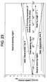
- Fig.23 is a graph showing an ideal steering characteristic.
- the axis of ordinates denotes the vehicle speed V (forward 0 km/h to +7.5 km/h, reverse 0 km/h to -3.5 km/h)
- the axis of abscissas represents the steering angle ⁇ (0° to 200° each to right and left)
- the upper region of the ideal characteristic line A and the lower region of the ideal characteristic line B are the neutral steering region, and the region enclosed by both lines A and B is the over-steering region.
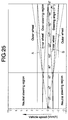
- Fig.24 shows the outer wheel ratio coefficient for determining the speed of outer wheel of the driven wheels during turning Vo in turning movement of the vehicle by only one driven wheel at various vehicle speeds V.
- the speed of inner wheel of the driven wheels during turning in turning movement of the vehicle by only one driven wheel is, of course, 0 km/h.
- the speed of outer wheel of the driven wheels during turning Vo is kept at a predetermined value of ⁇ 1.0 km/h same as vehicle speed V.
- the speed of inner wheel of the driven wheels during turning Vi decreases gradually from ⁇ 1 km/h in order to maintain the neutral steering state.
- This speed of inner wheel of the driven wheels during turning Vi is determined by multiplying the speed of outer wheel of the driven wheels during turning Vo by the ratio Vi/Vo on the neutral line N in Fig.19.
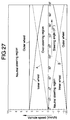
- the speed of outer wheel of the driven wheels during turning Vo is kept at ⁇ 2.5 km/h same as the vehicle speed V, while the speed of inner wheel of the driven wheels during turning Vi gradually decreases from ⁇ 2.5 km/h.
- the steering angle ⁇ for changing from the neutral steering state to over-steering state is small in low speed running and large in high speed running.
- the straight running stability is enhanced.
- the ideal steering characteristic shown in Fig.23 can be easily realized, and its characteristic may be easily changed.
- the speed change operating device M disposed beneath the seat 7 and the transmission system T disposed adjacently behind are connected through a pair of push-pull rods 251 R , 251 L extending in the longitudinal direction of the vehicle body, and therefore not only the balance is improved in the lateral direction of the vehicle body, but also the length of the push-pull rods 251 R , 251 L is shortened, and formation of deflection or backlash may be prevented.
- the vehicle speed is detected indirectly on the basis of the output of the first sensor 301 which detects the operating stroke of the change lever 10, but the vehicle speed may be detected directly, for example, by rotating speed sensors 308, 308 (see Fig.22) attached to axles 106 R , 106 L .
- the invention may be also applied to a three-wheel vehicle with one front wheel, a vehicle with front wheels and rear crawlers, or a vehicle with crawlers only without wheels.
- the driven wheel speed in the invention corresponds to the speed of the driven wheel for driving the crawlers.
- the front wheels may be caster type wheels that are not steered.
- the circular steering wheel with a large angle of rotation is used, but it may be replaced by a handle bar with a small angle of rotation.
- the embodiments relates to two-pump and two-motor transmission, but the invention may be also applied to one-pump and two-motor transmission. Besides, in the case of two-pump and two-motor transmission, instead of controlling the motor swash plate of the hydraulic motor, the pump swash plate of the hydraulic pump may be controlled.
- a working vehicle 1 includes front wheels Wf steered by a steering wheel 8, and rear wheels Wr driven through a transmission system T incorporating static hydraulic pressure type continuously variable transmissions.
- a speed change operating device M for controlling speed change of the transmission system T accelerates or decelerates right and left rear wheels Wr at same rotating speed by operation of a change lever 10, and also generates a difference in rotating speed between the right and left rear wheels Wr by operation of the steering wheel 8.
- the steering characteristic on the basis of operation of the steering wheel 8 varies depending on the vehicle speed set by the change lever 10, so that an appropriate steering characteristic may be obtained if the vehicle speed is changed.
Abstract
Description
- The present invention relates to an operating device in a vehicle provided with a pair of continuously variable transmissions, comprising a pair of right and left continuously variable transmissions such as static hydraulic pressure type continuously variable transmissions, belt-type continuously variable transmissions, cone-type continuously variable transmissions, and frictional-type continuously variable transmissions, for controlling the vehicle speed and steering by connecting the right and left continuously variable transmissions to right and left driven wheels, respectively.
- Such a steering control device in a vehicle provided with a pair of continuously variable transmissions has already been disclosed in Japanese Patent Publication No. 57-25428, Japanese Utility Model Publication No.49-38826, Japanese Patent Application Laid-open No.57-950, and Japanese Utility Model Publication No.40-31219.
- Steering characteristics in turning of vehicle include a neutral steering state in which a speed of an inner wheel of the driven wheels during turning and a speed of an outer wheel of the driven wheels during turning have a predetermined ratio suited to the turning radius so that slipping tendency does not occur in either inner or outer wheel, an under-steering state in which the speed of an inner wheel of the driven wheels during turning is higher than that in the neutral steering state, an over-steering state in which the speed of an outer wheel of the driven wheels during turning is higher than that in the neutral steering state, and stationary swing state in which the speed of an inner wheel of the driven wheels during turning is zero, among others.
- In the known operating device, however, the steering characteristics that are set on the basis of the operation of the steering angle setting means can not be varied, and a favorable steering characteristic cannot be always obtained along with changes of the vehicle speed.
- Further, in the known operating device, operation of vehicle speed setting means and operation of steering angle setting means are mixed in a speed change operating device, and transmitted to the transmission and therefore, if the operation of vehicle speed setting means interferes with the operation of steering angle setting means, or the operation of steering angle setting means interferes with the operation of vehicle speed setting means, there is a problem that the steering operation becomes complicated, or the steering feeling is impaired.
- Furthermore, in the know operating device, unless the speed change operating device and transmission are configured rationally, not only the balance of weight distribution and space distribution in the lateral direction of the vehicle body is worsened, but also the link mechanism for transmitting the motion of the speed change control member of the speed change operating device to the speed change control member of the transmission is complicated and extended in length, and accurate speed change control becomes difficult because a deflection or backlash is produced.
- It is a first object of the invention to always obtain a favorable steering characteristic regardless of vehicle speed changes.
- It is a second object of the invention to reliably operate the speed change operating device, while avoiding interference between the operation of vehicle speed setting means and operation of steering angle setting means.
- Further, it is a third object of the invention to realize an accurate speed change control by rationally disposing the speed change operating device and transmission in a vehicle provided with a pair of continuously variable transmissions, so as to improve the balance in the lateral direction of the vehicle body and design the link mechanism in a compact form.
- To achieve the first object, the invention provides an operating device in a vehicle provided with a pair of continuously variable transmissions, the vehicle comprising: left and right driven wheels connected to the pair of continuously variable transmissions, respectively; a vehicle speed setting means for setting a vehicle speed; and a steering angle setting means for setting a steering angle; in which outputs of the continuously variable transmissions are increased and decreased at substantially identical rotational numbers to each other based on an operation of the vehicle speed setting means, and the outputs of the continuously variable transmissions are increased and decreased at different rotational numbers from each other based on an operation of the steering angle setting means, thereby varying speeds of the driven wheels so as to control the vehicle speed and to conduct a steering, wherein the operating device includes a steering characteristic changeover means for changingover speed increasing and decreasing characteristics of the pair of continuously variable transmissions based on the operation of the steering angle setting means in accordance with the vehicle speed.
- According to the above arrangement, since the steering characteristic changeover means changes over the acceleration and deceleration characteristics of the pair of continuously variable transmissions on the basis of the operation of the steering angle setting means depending on the vehicle speed, a favorable steering characteristic suited to the vehicle speed is obtained whether at low vehicle speed or at high vehicle speed. Once the vehicle speed is set by the vehicle speed setting means, the turning speed and turning radius can be set in ideal state by operation of the steering angle setting means, and therefore it is possible not only but achieve stable turning with a small slip rate to the ground of the inner and outer wheels during turning, but also facilitate steering operation, enhance the working efficiency, and lessen the fatigue of the driver.
- To achieve the second object, the invention provides an operating device including the above arrangement, further comprising: a transmission system including the pair of continuously variable transmissions for changing rotational numbers of left and right driven wheels; a pair of speed change follower members provided in the transmission system; a vehicle speed setting means; and a speed change operating device for driving the speed change follower members at an identical phase based on an operation of the vehicle speed setting means, and for driving the speed change follower members at different phases based on an operation of the steering angle setting means; wherein the speed change operating device comprises: a pair of speed change driving members connected to the pair of speed change follower members; a pair of first speed change operating members which are pivotally supported, through a longitudinal shaft, on a lateral shaft operatively associated with the operation of the vehicle speed setting means for longitudinal swinging movement, and which are capable of longitudinally swinging integrally with the lateral shaft and capable of laterally swinging about the longitudinal shaft; a link member for connecting the pair of first speed change operating members to the pair of speed change driving members; a second speed change operating member operatively associated with the operation of the steering angle setting means for laterally swinging movement; and a mixing member which transmits a lateral swinging movement of the second speed change operating member to the first speed change operating members for laterally swinging the first speed change operating members, and which restrains a longitudinal swinging movement of the first speed change operating members from being transmitted to the second speed change operating member.
- In this arrangement, if the first speed change operating member is swung longitudinally about the lateral shaft by the operation of the vehicle speed setting means, the longitudinal oscillation of the first speed change operating member is prevented from being transmitted to the steering angle setting means by the mixing member, and if the second speed change operating member is swung laterally by the operation of the steering angle setting means, the first speed change operating member only oscillates laterally about the longitudinal shaft through the mixing member, so that its lateral oscillation may not be transmitted to the speed change setting means. It is hence possible to transmit the operation of the vehicle speed setting means and operation of steering angle setting means to the transmission by mixing while avoiding their mutual interference, thereby preventing complication of steering operation and worsening of steering feeling.
- To achieve the third object, the invention provides an operating device including the above arrangement, further comprising; a transmission system including the pair of continuously variable transmissions; a speed change operating device for controlling speed change characteristics of the continuously variable transmissions; a speed change control member provided in the speed change operating device; and another speed change control member provided in the transmission system, the speed change control members being connected together by a link member; the transmission system and the speed change operating device being mounted to a vehicle frame; wherein the speed change operating device is disposed in a lower portion of a seat provided at a substantially central portion of a vehicle body in both longitudinal and lateral directions, the transmission system is disposed in a rear of the speed change operating device at a position substantially centrally in the a lateral direction of the vehicle body, and the link member is disposed substantially along the longitudinal direction of the vehicle body.
- According to this arrangement, not only the waste space beneath the seat can be effectively utilized, but also the balance of weight distribution and space distribution in the lateral direction of the vehicle body can be enhanced, and moreover the link member for connecting between the both speed change control members can be defined to a minimum length, so that formation of deflection or backlash can be effectively prevented.
- The above and other objects, features and advantages of the invention will become apparent from a preferred embodiment taken in conjunction with the accompanying drawings.
- Figs.1 to 20 show a first embodiment of the invention; wherein
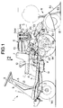
- Fig.1 is a side view of an entire working vehicle;
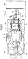
- Fig.2 is a view taken along an
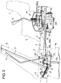
arrow 2 in Fig.1; - Fig.3 is an enlarged view of an essential portion Fig.1;
- Fig.4 is an enlarged view of an essential portion Fig.1;
- Fig.5 is an enlarged view of an essential portion Fig.2;
- Fig.6 is an enlarged view of an essential portion Fig.2;
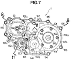
- Fig.7 is an enlarged view of an essential portion Fig.4;
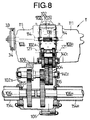
- Fig.8 is a sectional view taken along a line 8-8 in Fig.7;
- Fig.9 is an enlarged view of an essential portion Fig.8;
- Fig.10 is an enlarged view of an essential portion Fig.8;
- Fig.11 is a sectional view taken along a line 11-11 in Fig.7;
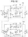
- Fig.12 is a hydraulic circuit diagram;
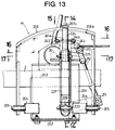
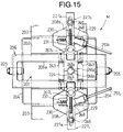
- Fig.13 is a magnified sectional view taken along a line 13-13 in Fig.6;
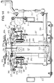
- Fig.14 is a sectional view taken along a line 14-14 in Fig.13;
- Fig.15 is a view taken along an
arrow 15 in Fig.13; - Fig.16 is a sectional view taken along a line 16-16 in Fig.13;
- Fig.17 is a sectional view taken along a line 17-17 in Fig.13;
- Fig.18 is a view for explaining the operation;
- Fig.19 is a graph showing the relation of steering angle and wheel speed ratio; and
- Fig.20 is a graph showing steering characteristic depending on the steering angle and vehicle speed.
- Fig.21 to Fig.27 show a second embodiment of the invention; wherein
- Fig.21 is a view corresponding to Fig.5;
- Fig.22 is a view corresponding to Fig.6;
- Fig.23 is a graph showing an ideal steering characteristic;
- Fig.24 is a graph showing the relation of outer wheel ratio coefficient and vehicle speed;
- Fig.25 is a graph showing wheel speed at vehicle speed ± 1.0 km/h;
- Fig.26 is a graph showing wheel speed at vehicle speed ± 2.5 km/h; and
- Fig.27 is a graph showing wheel speed at vehicle speed ± 3.5 km/h.
- Referring now to Fig.1 to Fig.20, a first embodiment of the invention is described below.
- As shown in Fig.1 and Fig.2, a riding
type working vehicle 1 having a pair of right and left front wheels Wf as follower wheels and a pair of right and left rear wheels Wr as driven wheels has a vehicle body frame F including a pair of right andleft side frames cross frames 3₁ to 3₅ extending in the lateral direction of the vehicle body for connecting both theside frames floor panel 4, asteering wheel post 5, and aseat base 6 are mounted to a front portion of the vehicle body frameF. A seat 7 on which a passenger sits is provided on theseat base 6. Thesteering wheel post 5 is provided at its upper portion with a steering wheel 8 for steering the right and left front wheels Wf, and generating a difference in rotating speed in the right and left rear wheels Wr through a static hydraulic continuously variable transmission described later. At the left side of thesteering wheel post 5, there is provided aclutch lever 9 for turning on or off the tension clutch which controls power transmission to the working machine (which will be described later), and at the right side of theseat 7, achange lever 10 is provided for moving the workingvehicle 1 back and forth. - The steering wheel 8 constitutes the steering angle setting means, and the
change lever 10 constitutes the vehicle speed setting means of the invention. - A single-cylinder four-cycle engine E is mounted on the upper surface of the rear portion of the vehicle body, such that a
crankshaft 11 of the engine E is directed to the lateral direction of the vehicle body, and acylinder 12 is directed upwardly and rearwardly. On upper portion of the engine E, afuel tank 13, anair cleaner 14A, and amuffler 14A are supported. In a lower portion of the engine E, a transmission system T for converting the driving force of the engine E into a hydraulic pressure and driving the right and left rear wheels Wr is mounted. A speed change operating device M installed beneath theseat 7 mixes the operation of the steering wheel 8 and operation ofchange lever 10 and transmits to the transmission system T so as to control the rotating speed of the right and left rear wheels Wr independently. A rotary working machine R driven by the engine E is connected to a rear end of the vehicle body. - As clear from Fig.3 and Fig.5, a
gear 22 is secured to the lower end of asteering shaft 21 connected to the steering wheel 8, and asector gear 24 pivotally supported by apivot 23 is engaged with thegear 22. Right and left knuckles 25R, 25L for pivotally supporting the right and left front wheels Wf are shaped in an L-form, and are supported so as to be free to swivel onguide tubes plate 40 laterally swingably pivoted on the lower part of the cross frame through astepped bolt 39. Right and leftknuckle arms tie rod 28, and theleft knuckle arm 27L andsector gear 24 are mutually connected through asteering rod 29. - When the steering wheel 8 is operated, the left front wheel Wf is steered through the steering
shaft 21,gear 22,sector gear 24, steeringrod 29, leftknuckle arm 27L, and left knuckle 25L, and further the right front wheel Wf is steered from the leftside knuckle arm 27L through thetie rod 28,right knuckle arm 27R and right knuckle 25R. The maximum steering angle of the steering wheel 8 is 200° each clockwise and counterclockwise, and it is set so that the steering angle of the outer front wheel Wf during turning is 50° when the steering angle is 200°. - As clear from Fig.4 and Fig.6, the
change lever 10 is pivoted for swinging movement longitudinally and laterally through apivot 30 extending in the lateral direction of the vehicle body. When thechange lever 10 is at neutral position N, the workingvehicle 1 is stopped, and when thechange lever 10 is swung forward from the neutral position, the workingvehicle 1 begins to run forward at 0 km/h to +7.5 km/h. When the forward swing angle is 14°, thechange lever 10 is at the working top position F₁, and the vehicle speed is +2.5 km/h. When the forward swing angle is 42°, thechange lever 10 is at the traveling top position F₂, and the vehicle speed is +7.5 km/h. When thechange lever 10 is swung backward from the neutral position, the workingvehicle 1 begins to run backward at 0 km/h to -3.5 km/h, and at the backward swing angle of 20°, thechange lever 10 is at the reverse top position R, and the and the vehicle speed is -3.5 km/h. - The maximum vehicle speed in forward running of +7.5 km/h, and the maximum vehicle speed in reverse running of -3.5 km/h can be changed arbitrarily, and the maximum vehicle speed in forward running and reverse running may be set, for example, slower than the above values.
- Referring then to Figs. 7 to 12, the structure of the transmission system T for transmitting the driving force of the engine E to the right and left rear wheels Wr is described below.
- In Figs.7 and 8, the transmission system T includes a
transmission case 102, a pair of static hydraulic continuouslyvariable transmissions transmission case 102 respectively, aspeed reduction device 104 disposed in thetransmission case 102, and a pair ofaxles transmission case 102 respectively, and right and left rear wheels Wr are provided at outer ends of theseaxles - The
transmission case 102 is composed by joining open ends ofright case half 102R and leftcase half 102R split on a plane orthogonal to an axial line of theaxles bolts 105. A lower half of outer side of theleft case half 102L is more projected than an upper half thereof , so as to form astep 109 therebetween. Whereas theright case half 102R is formed generally flat on the outer side surface. In this way, thetransmission case 102 has anarrow portion 102A above thestep 109 and awide portion 102B below thestep 109, and a pair of static hydraulic pressure type continuouslyvariable transmissions narrow portion 102A. - The right and left
axles bearings wide portion 102B of thetransmission case 102. - As shown in Figs.7 and 9, right and left static hydraulic pressure continuously
variable transmissions variable transmissions distribution plate 110 bolted separably to the outer side of the case halves 102R, 102L of the same side, ahousing 111 bolted to thisdistribution plate 110, and ahydraulic pump 112 and ahydraulic motor 113 disposed in thehousing 111. Thehydraulic pump 112 includes apump shaft 114 penetrating through thedistribution plate 110,pump cylinders 115 spline coupled to thepump shaft 114 and slidably and rotatably connected closely with thedistribution plate 110, multiple pump plungers 116 slidably fitted to thepump cylinders 115 in an annular arrangement surrounding thepump shaft 114, apump swash plate 117 abutting against outer ends of these pump plungers 116, and aswash plate holder 119 for bearing its back side with athrust bearing 118, and theswash plate holder 119 is supported on thehousing 111 through a pair oftrunnion shafts 120 of which axial line is orthogonal to the axial line of thepump shaft 114, and thepump swash plate 117 is tilted between one maximum inclination position (forward top position) and other maximum inclination position (reverse top position) through an erect position (neutral position) orthogonal to thepump shaft 114. At the outer ends of thetrunnion shafts 120 of the right and leftswash plate holders 119, speed change arms 249R, 249L (speed change follower member, speed change control member) are secured, and by turning these speed change arms 249R, 249L, the angle of eachswash plate 117 can be adjusted. - On the other hand, the
hydraulic motor 113 includes amotor shaft 121 penetrating through thedistribution plate 110,motor cylinders 122 spline coupled with themotor shaft 121 and slidably and rotatably connected closely with thedistribution plate 110, a large number ofmotor plungers 123 annularly arranged such as to surround themotor shaft 121 and slidably fitted to themotor cylinders 122, and amotor swash plate 124 abutting against outer ends of thesemotor plungers 123, and the back side of themotor swash plate 124 is supported in thehousing 111 through athrust bearing 125 in a state inclined by a specific angle to themotor shaft 121. - The right and left
pump shafts motor shafts - As shown in Fig.12, in the static hydraulic pressure continuously
variable transmissions hydraulic pump 112 andhydraulic motor 113 are mutually connected through a hydraulic pressureclose circuit 126. In the hydraulic pressureclose circuit 126, abypass passage 127 is provided for connecting between a high pressure side and a low pressure side of thecircuit 126, and arelease valve 128 opened and closed by manual operation is interposed. Thehydraulic pump 112 is connected to a workingoil supply pump 129 driven by thepump shaft 114. The workingoil supply pump 129 is to pump up the working oil from anoil sump 130 to send under pressure to anoil feed passage 131, and theoil feed passage 131 is connected to the high pressure side and low pressure side of the hydraulic pressureclose circuit 126 through one-way valves oil feed passage 131 may be connected to theoil sump 130 throughrelief valve 134 andsuction valve 135 which are in mutual parallel relation. - When the
release valve 128 is closed, if thehydraulic pump 112 is driven in a state where thepump swash plate 117 is inclined to the forward side, the working oil flows in the hydraulic pressureclose circuit 126 in the direction of solid line arrow. At that time, themotor shaft 121 of thehydraulic motor 113 rotates normally at the ratio of the capacity of thehydraulic pump 112 and the capacity of thehydraulic motor 113 at this time as the speed change ratio. On the other hand, if thepump swash plate 117 is inclined to the reverse side, the working oil flows in the hydraulic pressureclose circuit 126 in the direction of broken line arrow, so that themotor shaft 121 rotates reversely. At that time, if oil leak occurs in the hydraulic pressureclose circuit 126, one of the one-way valves oil supply pump 129 into the hydraulic pressureclose circuit 126. If a pressure in theoil feed passage 131 is increased by a certain value, therelief valve 134 is opened so as to prevent a pressure in theoil feed passage 131 from excessively increasing. When the high pressure side and low pressure side are suddenly inverted in the hydraulic pressureclose circuit 126 due to an engine brake, if a supply of the working oil to the low pressure side from the workingoil supply pump 129 is insufficient, thesuction valve 135 is opened, and the oil in theoil sump 130 is sucked into the low pressure side, thereby preventing air suction by the hydraulic pressureclose circuit 126. - In Fig.9, the
oil sump 130 is defined between both the case halves 102R, 102L of thetransmission case 102. Inside of eachdistribution plate 110, there is an oil filter 136 immersed in theoil sump 130 through each suction port of the workingoil supply pump 129 andsuction valve 135, and the working oil to be supplied into the workingoil supply pump 129 andsuction valve 135 is filtered. - As shown in Figs.9 and 10, the speed reduction device 104 includes first and second intermediate shafts 140₁, 140₂ rotatably supported, in parallel to the axles 106R, 106L, on the narrow portion 102A and wide portion 102B of the transmission case 102, respectively, a pair of right and left first small gears 141R, 141L secured to the inner ends of the right and left motors 121, 121, respectively, a pair of right and left first large gears 142R, 142L engaged with the first gears 141R, 141L and rotatably supported on the first intermediate shaft 140₁, a pair of right and left second small gears 143R, 143L formed integrally with opposed ends of the first large gears 142R, 142L, respectively, a right second large gear 144R engaged with the right second gear 143R coupled by key or spline to the right end of the second intermediate shaft 140₂ facing the narrow portion 102A of the second intermediate shaft a left second large gear 144L engaged with the left second gear 143L and rotatably supported on the second intermediate shaft 140₂ adjacent to the left side of the right second large gear 144R, a right final gear 146R rotatably supported on the second intermediate shaft 140₂ and coupled to the left end of the left second large gear 144L through a dog clutch 145, a clutch body 147 coupled by key or spline with the second intermediate shaft 140₂ at the left side of the right final gear 146R, a left final gear 146L rotatably supported on the second intermediate shaft 140₂ and coupled to the left end of the clutch body 147 through a dog clutch 148, and a pair of right and left final large gears 149R, 149L spline coupled with the right and left axles 106R, 106L and engaged with the right and left final gears 146R, 146L, respectively. The driving force of the right side
hydraulic motor 113 is transmitted to theleft side axle 106L, and the driving force of the left sidehydraulic motor 113 is transmitted to theright side axle 106R. - As shown in Figs.7 and 11, in the
narrow portion 102A of thetransmission case 102, a pair of right and left brake shafts 150R, 150L parallel to the firstintermediate shaft 140₁ and coaxial with each other are relatively rotatably supported, and these brake shafts 150R, 150L are secured to a pair of brake gears 151R, 151L to be engaged with the first large gears 142R, 142L respectively. The right and left brake shafts 150R, 150L are projected to the right and left sides of thenarrow portion 102A, and are respectively provided with brake devices 152R, 152L operated by a tension of abrake lever 153. - Instead of engaging gears 151R, 151L with the first large gears 142R, 142L, the brake gears 151R, 151L may be engaged with the second gears 144R, 144L.
- As shown in Figs.4 and 6, one of the
pump shafts 114 projects outward from the front part of theleft case half 102L. Anendless belt 34 is wound between atransmission drive pulley 32 provided on thecrankshaft 11 of the engine E and a transmission drivenpulley 33 provided in the onepump shaft 114. Atension pulley 38 is provided at a tip end of a tensionpulley support arm 37 which is pivoted on apivot 35 and biased by aspring 36. Thetension pulley 38 abuts against theendless belt 34 to generate a predetermined tension. - In this way, the driving force of the engine E is distributed to the
pump shafts variable transmissions pulley 32, theendless belt 34, and the transmission drivenpulley 33, and such distributed driving forces are properly changed in speeds, and then, outputted to thespeed reduction device 104 throughcorresponding motor shafts speed reduction device 104 from themotor shaft 121 of the right side static hydraulic pressure continuouslyvariable transmission 103R is transmitted to theleft side axle 106L, whereas the driving force outputted to thespeed reduction device 104 from themotor shaft 121 of the left side static hydraulic pressure continuouslyvariable transmission 103L is transmitted to theright side axle 106R, so that the right and left rear wheels Wr are driven to travel the workingvehicle 1. - In this case, in the right and left static hydraulic pressure type continuously
variable transmissions swash plates motor shafts vehicle 1 travels forward. And if the both pumpswash plates motor shafts vehicle 1 can travel backward. Moreover, by varying the speed change ratio of the right and left static hydraulic pressure type continuouslyvariable transmissions pump swash plates motor shafts vehicle 1 can turn. - The rotating speed of the engine E is variable, but it is fixed at 3300 RPM in an ordinary operating state.
- As clear from Figs.7 and 9, the transmission system T has a pair of right and left
hydraulic motors hydraulic pumps speed reduction device 104 is disposed in the rear of thehydraulic motors axles axles - Relating to Figs.1 to 6, a transmission of a power from the engine E to the rotary working machine R is described below.
- A working machine-lifting/lowering
shaft 62 extending in the lateral direction of the vehicle body is rotatably supported on abracket 61 projecting backward from therear-most cross frame 3₅. A working machine drivepulley 63 provided on thecrankshaft 11 of the engine E and a working machine drivenpulley 64 provided on the working machine-lifting/loweringshaft 62 are connected through anendless belt 65, and a tension clutch C for controlling the tension of theendless belt 65 is connected to theclutch lever 9 pivoted to the vehicle body front portion swingably in the longitudinal direction through apivot 66. - That is, a
transmission shaft 68 extending in the vertical direction is rotatably supported on abracket 67 provided on theleft side frame 2, and anarm 69 secured to thistransmission shaft 68, and the lower end of theclutch lever 9 are connected through alink 70. Atension pulley 73 provided at one end of an L-shapedsupport arm 72 having the intermediate portion pivoted through a pivot 71 abuts against theendless belt 65, and the other end of thesupport arm 72 andother arm 60 secured to thetransmission shaft 68 are connected withBowden wire 75 through abuffer spring 74. Thetransmission shaft 68 is biased in the counterclockwise direction in Fig.6 (that is, OFF direction of tension clutch C) by areturn spring 76. - When the
clutch lever 9 is pushed forward to turn on the tension clutch C, thetransmission shaft 68 is turned in the clockwise direction from the OFF position to the ON position against thereturn spring 76 to pull theBowden wire 75, and thesupport arm 72 oscillates, so that thetension pulley 73 is pushed to theendless belt 65. In this way, the tension clutch C is turned on, and the rotation of thecrankshaft 11 of the engine E is transmitted to the working machine-lifting/loweringshaft 62. When thetransmission shaft 68 turns from the OFF position to the ON position, it passes the neutral point, and therefore thetransmission shaft 68 is stably held at the ON position by the tension of thebuffer spring 74 through theBowden wire 75. When theclutch lever 9 is pulled back to turn off the tension clutch C, thetransmission shaft 68 is turned to the OFF position by the elastic force of thereturn spring 76, and is held there stably. - A
rear chain case 79 is coupled through anintermediate case 78 to the rear end of afront chain case 77 pivoted on the working machine-lifting/loweringshaft 62 so as to be swingable vertically, and the rotary working machine R including thefront chain case 77,intermediate case 78, andrear chain case 79 is driven vertically by a workingmachine elevating cylinder 80 attached to thebracket 61. That is, thefirst bracket 85 andsecond bracket 86 are pivoted on the working machine-lifting/loweringshaft 62 so as to be swingable vertically, and afirst bracket 85 is coupled with therear chain case 79 through acoupling member 87, and asecond bracket 86 is connected to the workingmachine elevating cylinder 80. Thesecond bracket 86 is opposed to the lower side of thefirst bracket 85, and when thesecond bracket 86 is swung vertically by the workingmachine elevating cylinder 80, thefirst bracket 85 pressed to thesecond bracket 86 oscillates upward together with the rotary working machine R. If the workingmachine elevating cylinder 80 does not operate, the rotary working machine R can oscillate freely upward about the working machine-lifting/loweringshaft 62 by the reaction from the ground. - A plurality of tilling
blades 81 provided at the rear end of therear chain case 79 are connected to the working machine-lifting/loweringshaft 62 by a chain transmission mechanism not shown accommodated in thefront chain case 77,intermediate chain case 78, andrear chain case 79 and driven for rotation.Reference numeral 82 in the drawing denotes a cover for thetilling blades - As mentioned herein, the
cylinder 12 of the engine E mounted on the rear part of the vehicle body frame F is directed upward and rearward, and the working machine-lifting/loweringshaft 62 is arranged in the lower space of thecylinder 12 of the engine E in side view, and therefore the waste space behind the vehicle body frame F can be effectively utilized. Moreover, the rotary working machine R can be brought closer to the vehicle body to decrease the moment transmitted from the rotary working machine R to the vehicle body to the utmost, which unnecessitates a reinforcement of the vehicle body so that the weight can be reduced. Still more, the followability of the rotary working machine R to the vehicle body is improved, and a tilling operation of a head land becomes easy and thus, non-tilled land decreases, and the stability of workingvehicle 1 is enhanced. - As clear from Fig.1, when the rotary working machine R reaches the chain line position which is the upward swing end, an upper end of the rotary working machine R is lower than an upper end of the
muffler 14M. Therefore, it is not only possible to enhance the stability by keeping low the position of center of gravity of the rotary working machine R, but also the rear visibility is improved because blocking of the vision of the driver seated on theseat 7 by the rotary working machine R is prevented. Still more, the space S between the rotary working machine R andmuffler 14M is widely kept, and the exhaust gas emitted from the exhaust 14M₁ of themuffler 14M is swiftly diffused to flow out backward and sideways, and the exhaust hardly flows to the driver side, and a comfortable working is realized. - Referring next to Figs.13 to 18, the structure of speed change operating device M for moving the working
vehicle 1 back and forth, and turning right and left by mixing the operation of the steering wheel 8 and operation ofchange lever 10 is described in detail below. The speed change operating device M constitutes the steering characteristic changeover means of the invention. - The speed change operating device M has a
base member 201 of a C-shaped section having right and left side walls and a bottom wall, with an upper surface opened. Asupport plate 202 superposed with the lower side of thebase member 201 is suspended and supported byside frames Pivots brackets base member 201. Front and rear lower ends of a guide member 206 (second speed change operating member) in a reverse U form in side view are pivoted on thesepivots - A pair of Bowden wires 208R, 208L coupled at one end to a pair of
wire joints guide member 206 are coupled at other end to the sector gear 24 (see Fig.5) turned by the steering wheel 8. Therefore, by operating the steering wheel 8 to turn the workingvehicle 1, theguide member 206 oscillates laterally about thepivots - In the lower part of the
base member 201, a rotary shaft 209 (lateral shaft) extending in the lateral direction is rotatably supported. Anarm 210 secured to thepivot 30 of thechange lever 10 and anarm 211 secured to the right end of therotary shaft 209 are coupled through arod 212, and by swing thechange lever 10 back and forth, therotary shaft 209 turns. - A
first swing member 221 formed in a U form in side view is fitted to pinch the middle of therotary shaft 209, and is pivoted so as to be free to oscillate laterally by a lowerpivotal pin 222 penetrating through therotary shaft 209. Twobolts rotary shaft 209 at right and left sides of the lowerpivotal pin 222 are freely fitted to thefirst swing member 221. Therefore, thefirst swing member 221 can finely adjust the angle in the lateral direction about the lowerpivotal pin 222 by the portion of the gap between thebolts first swing member 221, and it can be fixed by tightening thebolts - At the upper end of the
first swing member 221, the lower end of a mixing lever 224 (mixing member) is pivoted so as to be swingable laterally through an upperpivotal pin 225. The mixinglever 224 is freely fitted to aguide groove 206a formed in the longitudinal direction on the top of theguide member 206. Therefore, by operating thechange lever 10, when thefirst swing member 221 is swung longitudinally together with therotary shaft 209, the mixinglever 224 oscillates longitudinally along theguide groove 206a. By operating the steering wheel 8, when theguide member 206 is swung laterally about thepivots lever 224 abutting and pressed to theguide groove 206a oscillates laterally about the upperpivotal pin 225. At this time, by the gap δ (see Fig.14) formed between the mixinglever 224 and guidegroove 206a, the mixinglever 224 does not oscillate at thesteering angle 0° to
± 100 ° of the steering wheel 8, but oscillates at the steering angle of ±100° to
±200°. - On a pair of right and left
pivots base member 201, base ends of a pair of right and leftcontrol arms 227R, 227L (speed change control member, speed change drive member) are supported so as to be swingable longitudinally throughcollars pivot 226, upper and lowerneutral plates neutral spring 231, and between the twoneutral plates neutral pin 232 fixed downward in thecontrol arms neutral pin 233 fixed upward in thebase member 201 are pinched. Therefore, thecontrol arms - On the other hand, at right and left sides of the
first swing member 221, the lower ends of a pair ofsecond swing members 241R, 241L (first speed change operating members) are pivoted on therotary shaft 209 throughpins 242, 242 (longitudinal shafts) so as to be swingable laterally. The pair ofsecond swing members springs arc recesses lever 224, and their confronting surface abuts against the right and left outer surfaces of thefirst swing member 221, so as to be stably held at the neutral position. - At the outer ends of the pair of
second swing members 241R, 241L (first speed change operating members), corresponding inside ball joints 244, 244 are provided. At the front ends of thecontrol arms slots control arms slots pins pull rods 247R, 247L (link members) capable of adjusting the length in a turnbuckle system. When the mixinglever 224 is at the vertical neutral position, the push-pull rods control arms pins slots control arms - A pair of front ball joints 248, 248 provided in the middle of the right and left
control arms trunnion shafts change lever 10 and steering wheel 8 are operated, in cooperation with the oscillation of thecontrol arms - As described herein, the speed change operating device M is disposed beneath the
seat 7 provided in the middle in the longitudinal direction and lateral direction of the vehicle body, and the transmission system T is disposed closely behind the speed change operating device M, and thecontrol arms variable transmissions seat 7 can be effectively utilized, but also the balance of weight distribution and space distribution in the lateral direction of the vehicle body may be enhanced, and moreover the push-pull rods 251R, 251L are kept to a minimum required length, so that formation of deflection and backlash may be prevented. - The action of the embodiment of the invention having such constitution is described below.
- When the right and left
control arms variable transmissions vehicle 1 runs forward at a vehicle speed of 0 km/h to +7.5 km/h. When the right and leftcontrol arms variable transmissions vehicle 1 runs backward at a vehicle speed of 0 km/h to -3.5 km/h. When the workingvehicle 1 turns, a difference is caused in the moving angle of the right and leftcontrol arms vehicle 1 is turned. Or by driving only the outer wheel of the driven wheels during turning and stopping the driving of the inner wheel of the driven wheels during turning, the workingvehicle 1 makes a stationary swing. - The relation between operation of the steering wheel 8 and change
lever 10 and behavior of the workingvehicle 1 is described below while referring to Fig.18. - When the
change lever 10 is at the neutral position, the workingvehicle 1 is stopped, and at this time the right and left push-pull rods control arms pins pull rods slots control arms 227R, 227L (see Fig.18 (A)). - At this time, when the steering wheel 8 is operated, for example, in left turning direction, the
guide member 206 begins to oscillate to the right side around thepivots guide groove 206a of theguide member 206 abuts against the mixinglever 224, and the mixinglever 224 oscillates about the upperpivotal pin 225. As the mixinglever 224 oscillates in the right direction about the upperpivotal pin 225, the rightsecond swing member 241R begins to oscillate to the right side about thepin 242, resisting the neutral thrustingsprings second swing member 241L is held at the origin, abutting against thefirst swing member 221. - In this way, if the right
second swing member 241R is tilted to the right side and the right push-pull rod 247R moves to the right direction, the outside ball joint 246 at its front end only slides within theslot 227a from point A₀ to point A₁ in Fig.18 (A), so that theright control arm 227R is held at the neutral position. - When the
change lever 10 is moved forward from the neutral position in order to run forward the workingvehicle 1, therotary shaft 209 connected to thechange lever 10 turns forward, and the right and leftsecond swing members rotary shaft 209 also move forward. In consequence, the inside ball joints 244, 244 provided at the upper ends of the right and leftsecond swing members pull rods - As a result, the right and left
control arms slots pins neutral springs 231, 231 (see Fig.18 (B)). In this way, when the right and leftcontrol arms vehicle 1 runs forward at a vehicle speed (for example, +5.0 km/h) corresponding to the moving extent. - At this time, when the steering wheel 8 is operated, for example, in left turning direction in a steering angle range of ϑ = 100° to 200°, the right push-
pull rod 247R moves to the right direction along with the oscillation of thesecond swing member 241R. Consequently, the outside ball joint 246 at the front end of the push-pull rod 247R moves from point B₀ to point B₁ in Fig.18 (B), and thereby the forward swing angle of thecontrol arm 227R decreases to the chain line position. Thus, the rotating speed of themotor shaft 121 of the right static hydraulic pressure type continuouslyvariable transmission 103R decreases, and the left rear wheel Wr slows down or stops, thereby making a smooth left turning. - When the
change lever 10 is moved backward from the neutral position, the right and leftcontrol arms vehicle 1 runs backward at a vehicle speed (for example, -3.5 km/h) corresponding to the reverse moving extent of thecontrol arms 227R, 227L (see Fig.18 (C)). - In the case of reverse running, too, when the steering wheel 8 is operated in left turning direction in a steering angle range of ϑ = 100° to 200°, the outside ball joint 246 moves from point C₀ to point C₁ in Fig.18 (C), and the reverse swing angle of the
right control arm 227R decreases to the chain line position, and the rotating speed of themotor shaft 121 of the right static hydraulic pressure type continuouslyvariable transmission 103R decreases, and the left rear wheel Wr slows down or stops, thereby making a smooth left turning. - Herein is explained the case of operating the steering wheel 8 in the left turning direction, and it is substantially the same when the steering wheel 8 is operated in the right turning direction. Meanwhile, by varying the length of the
slots control arms - As described so far, by the speed change operating device M of simple structure with high durability, the operation of steering wheel 8 and operation of
change lever 10 can be mixed, and the transmission system T can be controlled. Moreover, if either steering wheel 8 or changelever 10 is operated, its operation does not interfere with the other, and the operation by the driver is simplified and the fatigue can be lessened. - In the case of straight running of the working
vehicle 1 by moving thechange lever 10 either forward or backward, incidentally, a difference may be caused in the rotating speed of the right and left rear wheels Wr due to slight difference in characteristics of the right and lefthydraulic motors hydraulic pumps vehicle 1 may be shifted to right or left in spite of the intention of the driver. In such a case, the turning tendency of the workingvehicle 1 may be corrected in the following manner. - That is, the working
vehicle 1 is allowed to run with thebolts vehicle 1 may run straightly in this state, for example, the length of push-pull rods 251R, 251L is adjusted finely. Then by tightening thebolts first swing member 221 on therotary shaft 209, thereafter the mixinglever 224 oscillates laterally about the upperpivotal pin 225. - Referring then to Figs.19 and 20, changes of speed of inner wheel of the driven wheels during turning and speed of outer wheel of the driven wheels during turning are explained in detail in relation to the steering angle ϑ and vehicle speed V.
- In the steering angle region of ϑ = 0° to 100°, the wheel speed ratio Vi/Vo of speed of inner wheel of the driven wheels during turning Vi to speed of outer wheel of the driven wheels during turning Vo is always set at 1.0 regardless of the vehicle speed. As a result, in the steering angle region of ϑ = 0° to 100°, the speed of outer wheel of the driven wheels during turning Vo and speed of inner wheel of the driven wheels during turning Vi are matched to be set in differential lock state, so that straight running stability in small steering angle is enhanced. When the steering angle exceeds ϑ = 100°, the wheel speed ratio Vi/Vo becomes smaller than 1.0, and the speed of inner wheel of the driven wheels during turning Vi decreases gradually while the speed of outer wheel of the driven wheels during turning Vo remains constant, thereby changing to under-steering state, neutral steering state, over-steering state, or turning state only by one driven wheel.
- The steering angle at which the wheel speed ratio Vi/Vo becomes smaller than 1.0 is not limited to ϑ = 100°, and it may be properly changed in a range of 60° and 120°.
- In Fig.19, when the vehicle speed V is relatively low (that is, at vehicle speed of V = 0 km/h to ±2.5 km/h), by exceeding the steering angle ϑ = 100°, the wheel speed ratio Vi/Vo decreases relatively suddenly from 1.0, and finally intersects with the line P of turning movement of the vehicle by only one wheel, at wheel speed ratio Vi/Vo = 0, crossing the intermediate neutral steering line N.
- The neutral steering line N is to give the wheel speed ratio Vi/Vo to be in neutral steering state at each steering angle ϑ. The value of wheel speed ratio Vi/Vo on the neutral steering line N is determined by

- Therefore, in Fig.20, assuming a case of, for example, vehicle speed V = ± 1.0 km/h, in the differential lock region of steering angle ϑ = 0° to 100°, the wheel speed ratio Vi/Vo = 1.0, and the speed of outer wheel of the driven wheels during turning Vo and speed of inner wheel of the driven wheels during turning Vi are matched to be set in a virtual differential lock state. In the under-steering region of steering angle ϑ = 100° to 105°, the wheel speed ratio Vi/Vo ≦ 1.0, and the speed of inner wheel of the driven wheels during turning Vi decreases gradually, but still the under-steering state is maintained. Reaching the steering angle ϑ = 105°, intersecting with the neutral steering line N, it falls in neutral steering state. In an over-steering region with the steering angle ϑ = 105° to 115° , the vehicle speed Vi/Vo further decreases to be set in over-steering state, and after intersecting with the line P of turning movement of vehicle by only one driven wheel, at steering angle ϑ = 115°, the wheel speed ratio is Vi/Vo = 0, thereby realizing the turning state of the vehicle only by one driven wheel, at the speed of inner wheel of the driven wheels during turning Vi = 0.
- In the case of vehicle speed V = ±2.5 km/h, passing through the differential lock region of steering angle ϑ = 0° to 100° and under-steering region of steering angle ϑ = 100° to 147°, at steering angle ϑ = 147°, intersecting with the neutral steering line N, it falls in neutral steering state, and further after the over-steering region at steering angle ϑ = 147° to 200° , it falls in the turning state of the vehicle only by one driven wheel, intersecting with the line P of turning movement of the vehicle by only one driven wheel at steering angle ϑ = 200°.
- In the case of vehicle speed V = ±2.5 km/h to ±2.9 km/h (not including V = ±2.5 km/h), the state changes to the differential lock region, under-steering region, neutral steering region, and over-steering region, depending on the increase of steering angle ϑ, but never falling in the state of turning movement of the vehicle by only one driven wheel. Exceeding the vehicle speed V = ± 2.9 km/h, depending on the increase of steering angle ϑ, the differential lock region is changed to an under-steering region, but never changing to a neutral steering region, an over-steering region, or a region of turning movement of the vehicle by only one driven wheel.
- As described herein, in the range of vehicle speed of V = 0 km/h to ±2.5 km/h, along with increase of steering angle ϑ, the state changes over from differential lock region to under-steering region to neural steering region to the over-steering region and to the region of turning movement of the vehicle by only one driven wheel. In the range of vehicle speed V = ±2.5 km/h to ±2.9 km/h (not including V = ±2.5 km/h), along with increase of steering angle ϑ, the differential lock state is changed to under-steering state to neutral steering state and to over-steering state. In the range of vehicle speed V = +2.9 km/h to +7.5 km/h and vehicle speed of V = - 2.9 km/h to - 3.5 km/h, along with the increase of steering angle ϑ, the differential lock state is changed to the under-steering state.
- Thus, at low speed where the vehicle body stability is high, the turning performance is enhanced by setting in the over-steering state or the state of turning movement of the vehicle by only one driven wheel, at a relatively small steering angle ϑ, and at high speed where the vehicle body stability is low, the vehicle body stability may be sufficiently maintained without using the over-steering state or the state of turning movement of the vehicle by only one driven wheel.
- A second embodiment of the invention is described below while referring to Figs.21 to 27.
- The second embodiment is intended to control the transmission system T electrically by the speed change operating device M installed beneath the
seat 7. As shown in Figs.21 and 22, an electronic control unit U having a microcomputer receives a signal from afirst sensor 301 for detecting the operating stroke of thechange lever 10, and a signal from asecond sensor 302 for detecting the operating stroke of the steering wheel 8 on the basis of the rotation of asector gear 24.Speed change plates 303R, 303L (speed change control members) connected to a pair of right and left speed change arms 249R, 249L of the transmission system T through push-pull rods 251R, 251L are rotated and driven by a pair of right and left motors 304R, 304L with speed reduction device connected to the electronic control unit U throughgears third sensors - The electronic control unit U calculates the command angles of the right and left speed change arms 249R, 249L on the basis of the signals from the
first sensor 301 andsecond sensor 302, and controls, by feedback, the rotation of the motors 304R, 304L with speed reduction device so that the actual angles of the right and left speed change arms 249R, 249L produced by thethird sensors - Fig.23 is a graph showing an ideal steering characteristic. In the graph, the axis of ordinates denotes the vehicle speed V (forward 0 km/h to +7.5 km/h, reverse 0 km/h to -3.5 km/h), and the axis of abscissas represents the steering angle ϑ (0° to 200° each to right and left), and the upper region of the ideal characteristic line A and the lower region of the ideal characteristic line B are the neutral steering region, and the region enclosed by both lines A and B is the over-steering region. That is, whether in forward or reverse run, in the state of vehicle speed V of less than 3.0 km/h, at low speed where the vehicle body stability is high, the turning performance is enhanced by changing from the small steering angle ϑ to over-steering state, and at high speed where the vehicle body stability is low, the vehicle body behavior can be stabilized by changing from the large steering angle ϑ to over-steering state. In the state of vehicle speed over V = ± 3.0 km/h, it is always the neutral steering state regardless of the steering angle ϑ.
- At vehicle speed under V = ±2.5 km/h, at the steering angle ϑ = 200°, the speed of inner wheel of the driven wheels during turning becomes 0 km/h to be set in the turning state of the vehicle by only one driven wheel state, and over vehicle speed V = ±2.5 km/h, even at the steering angle ϑ = 200°, a turning movement of the vehicle by only one driven wheel is not available.
- To obtain the characteristic of Fig.23, control of speed of inner wheel of the driven wheels during turning and speed of outer wheel during rotation is explained below.
- Fig.24 shows the outer wheel ratio coefficient for determining the speed of outer wheel of the driven wheels during turning Vo in turning movement of the vehicle by only one driven wheel at various vehicle speeds V. The outer wheel ratio coefficient changes linear from 2.65 at vehicle speed V = 0 km/h to 1.0 at ± 2.5 km/h, and by multiplying this outer wheel ratio coefficient by the vehicle speed V, the speed of outer wheel of the driven wheels during turning in turning movement of the vehicle by only one driven wheel is obtained. The speed of inner wheel of the driven wheels during turning in turning movement of the vehicle by only one driven wheel is, of course, 0 km/h.
- Fig.25 is a graph showing the speed of outer wheel of the driven wheels during turning Vo and speed of inner wheel of the driven wheels during turning Vi at vehicle speed V = ±1.0 km/h. In the neutral steering region at the upper side of the ideal characteristic line A, the speed of outer wheel of the driven wheels during turning Vo is kept at a predetermined value of ± 1.0 km/h same as vehicle speed V. On the other hand, from the steering angle ϑ = 0° to steering angle ϑ = 67° where the line of the vehicle speed V = ±1.0 km/h intersects with the ideal characteristic line A, the speed of inner wheel of the driven wheels during turning Vi decreases gradually from ± 1 km/h in order to maintain the neutral steering state. This speed of inner wheel of the driven wheels during turning Vi is determined by multiplying the speed of outer wheel of the driven wheels during turning Vo by the ratio Vi/Vo on the neutral line N in Fig.19.
- Exceeding the steering angle ϑ = 67°, the speed of inner wheel of the driven wheels during turning Vi decreases linearly, until speed of inner wheel of the driven wheels during turning Vi = 0 km/h at steering angle ϑ = 200°. On the other hand, exceeding the steering angle ϑ = 67°, the speed of outer wheel of the driven wheels during turning Vo increases linearly. Upon reaching the steering angle ϑ = 200°, the speed of outer wheel of the driven wheels during turning Vo is determined on the basis of the outer wheel ratio coefficient given in the graph in Fig.24. That is, the outer wheel ratio coefficient at the vehicle speed V = ±1.0 km/h is 2.0 times the vehicle speed V = ±1.0 km/h, that is, ±2.0 km/h.
- When the vehicle speed is V = ±1.0 km/h, the neutral steering state continues up to the steering angle ϑ = 67°, and exceeding the steering angle ϑ = 67°, the over-steering state is established, and turning movement of the vehicle by only one driven wheel is realized at steering angle ϑ = 200°.
- Fig.26 is a graph showing the speed of outer wheel of the driven wheels during turning Vo and speed of inner wheel of the driven wheels during turning Vi at vehicle speed V = ±2.5 km/h. In the neutral steering region up to steering angle ϑ = 167°, the speed of outer wheel of the driven wheels during turning Vo is kept at ±2.5 km/h same as the vehicle speed V, while the speed of inner wheel of the driven wheels during turning Vi gradually decreases from ± 2.5 km/h. Exceeding the steering angle ϑ = 167°, Vi decreases linearly, until speed of inner wheel of the driven wheels during turning Vi = 0 km/h at the steering angle ϑ = 200°. On the other hand, as clear from Fig.24, at the vehicle speed of V = ±2.5 km/h, since the outer wheel ratio coefficient is 1.0, the speed of outer wheel of the driven wheels during turning Vo when reaching the steering angle ϑ = 200° is 1.0 times the vehicle speed V = ±2.5 km/h, that is, ±2.5 km/h. Therefore, at the vehicle speed V = ± 2.5 km/h, the speed of outer wheel of the driven wheels during turning is kept at Vo = ±2.5 km/h over the entire region of steering angle ϑ = 0° to 200°.
- Thus, in the range of vehicle speed V = 0 km/h to ± 2.5 km/h, when the steering angle ϑ exceeds a specific angle, the neutral steering state is changed to over steering state, and the vehicle can turn by only one driven wheel when reaching the steering angle ϑ = 200° . The steering angle ϑ for changing from the neutral steering state to over-steering state is small in low speed running and large in high speed running.
- Fig.27 is a graph showing the speed of outer wheel of the driven wheels during turning Vo and speed of inner wheel of the driven wheels during turning Vi at vehicle speed V = ±3.5 km/h. In this case, the entire region of steering angle ϑ = 0° to 200° is the neutral steering region, and the speed of outer wheel of the driven wheels during turning Vo is kept at ±3.5 km/h same as the vehicle speed V, and the speed of inner wheel of the driven wheels during turning Vi decreases gradually from ± 3.5 km/h according to the characteristic of the neutral line N in Fig.19. Thus, by holding the neural steering state at high speed, the straight running stability is enhanced.
- The neutral state is always maintained in a range of vehicle speed of V = +3.0 km/h to +7.5 km/h in forward running, and in a range of vehicle speed of V = -3.0 km/h to -3.5 km/h in reverse running.
- Thus, according to the second embodiment for electrically controlling the transmission system T, the ideal steering characteristic shown in Fig.23 can be easily realized, and its characteristic may be easily changed.
- In the second embodiment, too, the speed change operating device M disposed beneath the
seat 7 and the transmission system T disposed adjacently behind are connected through a pair of push-pull rods 251R, 251L extending in the longitudinal direction of the vehicle body, and therefore not only the balance is improved in the lateral direction of the vehicle body, but also the length of the push-pull rods 251R, 251L is shortened, and formation of deflection or backlash may be prevented. - In the second embodiment, the vehicle speed is detected indirectly on the basis of the output of the
first sensor 301 which detects the operating stroke of thechange lever 10, but the vehicle speed may be detected directly, for example, by rotatingspeed sensors 308, 308 (see Fig.22) attached toaxles - Embodiments of the invention are described herein, but the invention is not limited to the illustrated embodiments alone, and various design changes are possible.
- For example, instead of the four-wheel vehicle shown in the embodiments, the invention may be also applied to a three-wheel vehicle with one front wheel, a vehicle with front wheels and rear crawlers, or a vehicle with crawlers only without wheels. In the vehicle with crawlers, the driven wheel speed in the invention corresponds to the speed of the driven wheel for driving the crawlers. In the vehicle with front wheels, the front wheels may be caster type wheels that are not steered.
- In the embodiments, as the steering angle setting means, the circular steering wheel with a large angle of rotation is used, but it may be replaced by a handle bar with a small angle of rotation.
- The embodiments relates to two-pump and two-motor transmission, but the invention may be also applied to one-pump and two-motor transmission. Besides, in the case of two-pump and two-motor transmission, instead of controlling the motor swash plate of the hydraulic motor, the pump swash plate of the hydraulic pump may be controlled.
- Instead of the static hydraulic pressure type continuously
variable transmissions
The invention as described above can be summarized as follows:
A workingvehicle 1 includes front wheels Wf steered by a steering wheel 8, and rear wheels Wr driven through a transmission system T incorporating static hydraulic pressure type continuously variable transmissions. A speed change operating device M for controlling speed change of the transmission system T accelerates or decelerates right and left rear wheels Wr at same rotating speed by operation of achange lever 10, and also generates a difference in rotating speed between the right and left rear wheels Wr by operation of the steering wheel 8. The steering characteristic on the basis of operation of the steering wheel 8 varies depending on the vehicle speed set by thechange lever 10, so that an appropriate steering characteristic may be obtained if the vehicle speed is changed.
Claims (13)
- An operating device in a vehicle provided with a pair of continuously variable transmissions, the vehicle comprising: left and right driven wheels connected to said pair of continuously variable transmissions, respectively; a vehicle speed setting means for setting a vehicle speed; and a steering angle setting means for setting a steering angle; in which outputs of said continuously variable transmissions are increased and decreased at substantially identical rotational numbers to each other based on an operation of said vehicle speed setting means, and said outputs of said continuously variable transmissions are increased and decreased at different rotational numbers from each other based on an operation of said steering angle setting means, thereby varying speeds of the driven wheels so as to control said vehicle speed and to conduct a steering, wherein said operating device includes a steering characteristic changeover means for changingover speed increasing and decreasing characteristics of said pair of continuously variable transmissions based on the operation of said steering angle setting means in accordance with the vehicle speed.
- An operating device according to claim 1, wherein in accordance with an increase in the steering angle, a deviation between speeds of both the driven wheels increases and the speed of an inner wheel of the driven wheels during turning decreases.
- An operating device according to claim 1, wherein speeds of both the driven wheels are held in a neutral steering state over an entire range of the steering angle when the vehicle speed exceeds a predetermined value.
- An operating device according to claim 1, wherein an operating region is provided in which when the vehicle speed is equal to or lower than a predetermined value, an inner wheel of the driven wheels during turning is stopped in accordance with an increase in the steering angle and the vehicle is turned only by an outer wheel of the driven wheels.
- An operating device according to claim 1, wherein a deviation between speeds of both the driven wheels is set small when the vehicle travels at a high speed, whereas said deviation is set large when the vehicle travels at a low speed.
- An operating device according to claim 1, wherein when the vehicle speed is equal to or lower than a predetermined value, if the steering angle exceeds a predetermined value, speeds of both the driven wheels are brought into an over-steering state, and in this over-steering state, the speed of an outer wheel of the driven wheels during turning increases and the speed of an inner wheel of the driven wheels during turning decreases.
- An operating device according to claim 1, wherein speeds of both the driven wheels are set substantially identical values when the steering angle is equal to or lower than a predetermined value.
- An operating device according to claim 1, wherein a neutral steering point is provided in which speeds of both the driven wheels are brought into a neutral steering state within a range of steering angles exceeding a predetermined value when the vehicle speed is equal to or lower than a predetermined value.
- An operating device according to claim 1, wherein the vehicle further includes a seat disposed substantially at a central portion of a vehicle body, a working machine disposed at a rear portion of the vehicle body for up and down movements, an engine disposed between said seat and said working machine, and a muffler mounted in the engine, wherein an upper end of the working machine when lifted to a highest position is set lower than an upper end of the muffler.
- An operating device according to claim 1, further comprising: a transmission system including said pair of continuously variable transmissions for changing rotational numbers of left and right driven wheels; a pair of speed change follower members provided in said transmission system; a vehicle speed setting means; and a speed change operating device for driving said speed change follower members at an identical phase based on an operation of said vehicle speed setting means, and for driving said speed change follower members at different phases based on an operation of said steering angle setting means; wherein said speed change operating device comprises: a pair of speed change driving members connected to said pair of speed change follower members; a pair of first speed change operating members which are pivotally supported, through a longitudinal shaft, on a lateral shaft operatively associated with the operation of said vehicle speed setting means for longitudinal swinging movement, and which are capable of longitudinally swinging integrally with said lateral shaft and capable of laterally swinging about said longitudinal shaft; a link member for connecting said pair of first speed change operating members to said pair of speed change driving members; a second speed change operating member operatively associated with the operation of said steering angle setting means for laterally swinging movement; and a mixing member which transmits a lateral swinging movement of said second speed change operating member to said first speed change operating members for laterally swinging said first speed change operating members, and which restrains a longitudinal swinging movement of said first speed change operating members from being transmitted to said second speed change operating member.
- An operating device according to claim 10, wherein said mixing member is fitted to a guide groove formed longitudinally in said second speed change operating member and is longitudinally swung integrally with said lateral shaft, and is also laterally swung following a lateral swinging movement of said second speed change operating member.
- An operating device according to claim 11, wherein said pair of first speed change operating members are biased toward a neutral position abutting against said mixing member, and only one of said first speed change operating members which is pressed by said mixing member swings laterally following a lateral swinging movement of said mixing member.
- An operating device according to claim 1, further comprising; a transmission system including said pair of continuously variable transmissions; a speed change operating device for controlling speed change characteristics of said continuously variable transmissions; a speed change control member provided in said speed change operating device; and another speed change control member provided in said transmission system, said speed change control members being connected together by a link member; said transmission system and said speed change operating device being mounted to a vehicle frame; wherein said speed change operating device is disposed in a lower portion of a seat provided at a substantially central portion of a vehicle body in both longitudinal and lateral directions, said transmission system is disposed in a rear of said speed change operating device at a position substantially centrally in the a lateral direction of said vehicle body, and said link member is disposed substantially along the longitudinal direction of said vehicle body.
Applications Claiming Priority (6)
| Application Number | Priority Date | Filing Date | Title |
|---|---|---|---|
| JP10312794 | 1994-05-17 | ||
| JP10312794 | 1994-05-17 | ||
| JP103127/94 | 1994-05-17 | ||
| JP7095606A JP2704855B2 (en) | 1994-05-17 | 1995-04-20 | Steering control device for continuously variable drive vehicle |
| JP9560695 | 1995-04-20 | ||
| JP95606/95 | 1995-04-20 |
Publications (2)
| Publication Number | Publication Date |
|---|---|
| EP0683087A1 true EP0683087A1 (en) | 1995-11-22 |
| EP0683087B1 EP0683087B1 (en) | 2002-07-31 |
Family
ID=26436828
Family Applications (1)
| Application Number | Title | Priority Date | Filing Date |
|---|---|---|---|
| EP95107559A Expired - Lifetime EP0683087B1 (en) | 1994-05-17 | 1995-05-17 | Operating device in vehicle provided with a pair of continuously variable transmissions |
Country Status (4)
| Country | Link |
|---|---|
| US (1) | US6543548B1 (en) |
| EP (1) | EP0683087B1 (en) |
| JP (1) | JP2704855B2 (en) |
| DE (1) | DE69527572T2 (en) |
Cited By (2)
| Publication number | Priority date | Publication date | Assignee | Title |
|---|---|---|---|---|
| EP0754613A1 (en) * | 1995-07-20 | 1997-01-22 | Honda Giken Kogyo Kabushiki Kaisha | Steering control device for vehicle having continuously variable transmission |
| CN106717159A (en) * | 2016-12-30 | 2017-05-31 | 重庆市永川区望城机械厂 | Multifunctional small tiller |
Families Citing this family (10)
| Publication number | Priority date | Publication date | Assignee | Title |
|---|---|---|---|---|
| US6629577B1 (en) * | 1998-07-02 | 2003-10-07 | Tuff Torq Corporation | Driving apparatus for speed changing and steering of a vehicle |
| US6540633B1 (en) * | 1998-09-25 | 2003-04-01 | Tuff Torq Corporation | Transmission for speed changing and steering of a vehicle |
| CA2409249C (en) * | 2001-10-25 | 2008-05-27 | Honda Giken Kogyo Kabushiki Kaisha | Electric vehicle |
| JP3950358B2 (en) * | 2002-04-24 | 2007-08-01 | 株式会社 神崎高級工機製作所 | Steering device for work vehicle |
| US6725954B1 (en) * | 2003-03-28 | 2004-04-27 | Honda Giken Kogyo Kabushiki Kaisha | Apparatus and method for steering a vehicle with zero turning radius capability |
| JP4605649B2 (en) * | 2005-03-22 | 2011-01-05 | 株式会社クボタ | Mower |
| JP4644056B2 (en) * | 2005-07-05 | 2011-03-02 | 本田技研工業株式会社 | Miwa management machine |
| JP5921158B2 (en) * | 2011-11-17 | 2016-05-24 | 株式会社クボタ | Working machine |
| CN105794336A (en) * | 2016-04-12 | 2016-07-27 | 彭宇良 | Four-wheeled differential driving friction tiller |
| CN113104137B (en) * | 2021-04-22 | 2022-11-29 | 广东雅迪机车有限公司 | Electric vehicle capable of stably running and avoiding forward tilting and overturning |
Citations (7)
| Publication number | Priority date | Publication date | Assignee | Title |
|---|---|---|---|---|
| FR1573169A (en) * | 1968-04-08 | 1969-07-04 | ||
| JPS4938826Y1 (en) | 1970-04-27 | 1974-10-24 | ||
| FR2418136A1 (en) * | 1978-02-27 | 1979-09-21 | Caterpillar Tractor Co | NEW COMBINATION OF A DIFFERENTIAL MECHANISM AND A TRANSMISSION, ESPECIALLY FOR VEHICLES |
| JPS57950A (en) | 1980-05-29 | 1982-01-06 | Yutani Juko Kk | Differential gear for hydraulic travelling vehicle |
| JPS5725428A (en) | 1980-06-14 | 1982-02-10 | Barmag Barmer Maschf | Friction false twisting machine |
| USRE34057E (en) * | 1988-03-09 | 1992-09-08 | Simplicity Manufacturing, Inc. | Steering mechanism for a zero turning radius vehicle |
| WO1993008063A1 (en) * | 1991-10-16 | 1993-04-29 | Mannesmann Aktiengesellschaft | Assisted steering system for non-trackbound vehicles |
Family Cites Families (24)
| Publication number | Priority date | Publication date | Assignee | Title |
|---|---|---|---|---|
| JPS5429972B2 (en) | 1972-08-18 | 1979-09-27 | ||
| US4549610A (en) * | 1979-06-05 | 1985-10-29 | Lely Cornelis V D | Vehicle with front and rear steerable wheels individually driven by hydraulic motors |
| US4399886A (en) * | 1980-12-09 | 1983-08-23 | Sundstrand Corporation | Controls for variable displacement motor and motors |
| JPS58141969A (en) * | 1982-02-17 | 1983-08-23 | Komatsu Ltd | Turn control method of hydraulic mechanical type speed change gear and steering unit |
| DE3241793A1 (en) * | 1982-11-11 | 1984-05-17 | Linde Ag, 6200 Wiesbaden | CONTROL DEVICE FOR DRIVING A VEHICLE WITH DIFFERENTIAL SPEED STEERING |
| US4631920A (en) * | 1983-04-05 | 1986-12-30 | Linde Aktiengesellschaft | Controls for the drive of a vehicle with differential speed steering |
| US4599855A (en) * | 1983-04-05 | 1986-07-15 | Linde Aktiengesellschaft | Controls for the drive of a vehicle with differential speed steering |
| US4527649A (en) * | 1983-04-18 | 1985-07-09 | Mauldin Herbert N | Paver steering apparatus |
| IT1161494B (en) * | 1983-07-11 | 1987-03-18 | Fiat Allis Europ | STEERING DEVICE FOR A VEHICLE EQUIPPED WITH HYDROSTATIC TRANSMISSION, IN PARTICULAR FOR A TRACKED EARTH-MOVING MACHINE |
| DE3569358D1 (en) * | 1984-02-07 | 1989-05-18 | Torotrak Dev Ltd | Driveline for a track-laying vehicle |
| JPS60206785A (en) * | 1984-03-29 | 1985-10-18 | Toyoda Mach Works Ltd | Power steering device |
| JPS62227819A (en) * | 1986-03-28 | 1987-10-06 | Toyota Autom Loom Works Ltd | Pitching abatement method for skid steering vehicle |
| DE3619401C2 (en) * | 1986-06-09 | 1999-03-18 | Linde Ag | Control device for a vehicle with differential speed steering |
| JPS63279975A (en) * | 1987-05-11 | 1988-11-17 | Toyota Autom Loom Works Ltd | Turning speed regulator for skid steering vehicle |
| US4914592A (en) * | 1987-12-03 | 1990-04-03 | Trw Inc. | Apparatus for controlling a steering-by-driving system |
| US5078222A (en) * | 1989-03-02 | 1992-01-07 | Agri-Fab, Inc. | Zero turn transmission |
| DE69228892T2 (en) * | 1991-02-08 | 1999-09-09 | Mitsubishi Heavy Ind Ltd | Crawler vehicle with hydraulic drive |
| US5258912A (en) * | 1991-06-24 | 1993-11-02 | General Motors Corporation | Wheel understeer speed control |
| CA2077427C (en) * | 1991-09-12 | 1998-05-05 | Ichiro Sakai | Vehicle automatic transmission control system |
| JP3017576B2 (en) * | 1991-10-04 | 2000-03-13 | 株式会社クボタ | Walking type work machine |
| JP3666879B2 (en) * | 1991-12-05 | 2005-06-29 | 日本精工株式会社 | Toroidal continuously variable transmission for four-wheel drive vehicles |
| JP2896002B2 (en) * | 1992-01-14 | 1999-05-31 | 株式会社クボタ | Four-wheel drive work vehicle |
| EP0559114B1 (en) * | 1992-03-03 | 1996-10-23 | Deutsches Zentrum für Luft- und Raumfahrt e.V. | Process for steering a road vehicle with front and rear wheel steering |
| JP2766129B2 (en) * | 1992-07-01 | 1998-06-18 | 株式会社クボタ | Work vehicle turning operation structure |
-
1995
- 1995-04-20 JP JP7095606A patent/JP2704855B2/en not_active Expired - Fee Related
- 1995-05-17 US US08/443,173 patent/US6543548B1/en not_active Expired - Fee Related
- 1995-05-17 EP EP95107559A patent/EP0683087B1/en not_active Expired - Lifetime
- 1995-05-17 DE DE69527572T patent/DE69527572T2/en not_active Expired - Lifetime
Patent Citations (7)
| Publication number | Priority date | Publication date | Assignee | Title |
|---|---|---|---|---|
| FR1573169A (en) * | 1968-04-08 | 1969-07-04 | ||
| JPS4938826Y1 (en) | 1970-04-27 | 1974-10-24 | ||
| FR2418136A1 (en) * | 1978-02-27 | 1979-09-21 | Caterpillar Tractor Co | NEW COMBINATION OF A DIFFERENTIAL MECHANISM AND A TRANSMISSION, ESPECIALLY FOR VEHICLES |
| JPS57950A (en) | 1980-05-29 | 1982-01-06 | Yutani Juko Kk | Differential gear for hydraulic travelling vehicle |
| JPS5725428A (en) | 1980-06-14 | 1982-02-10 | Barmag Barmer Maschf | Friction false twisting machine |
| USRE34057E (en) * | 1988-03-09 | 1992-09-08 | Simplicity Manufacturing, Inc. | Steering mechanism for a zero turning radius vehicle |
| WO1993008063A1 (en) * | 1991-10-16 | 1993-04-29 | Mannesmann Aktiengesellschaft | Assisted steering system for non-trackbound vehicles |
Cited By (3)
| Publication number | Priority date | Publication date | Assignee | Title |
|---|---|---|---|---|
| EP0754613A1 (en) * | 1995-07-20 | 1997-01-22 | Honda Giken Kogyo Kabushiki Kaisha | Steering control device for vehicle having continuously variable transmission |
| US5850886A (en) * | 1995-07-20 | 1998-12-22 | Honda Giken Kogyo Kabushiki Kaisha | Steering control device for vehicle having continuously variable transmission |
| CN106717159A (en) * | 2016-12-30 | 2017-05-31 | 重庆市永川区望城机械厂 | Multifunctional small tiller |
Also Published As
| Publication number | Publication date |
|---|---|
| EP0683087B1 (en) | 2002-07-31 |
| JPH0834363A (en) | 1996-02-06 |
| DE69527572T2 (en) | 2002-11-21 |
| DE69527572D1 (en) | 2002-09-05 |
| JP2704855B2 (en) | 1998-01-26 |
| US6543548B1 (en) | 2003-04-08 |
Similar Documents
| Publication | Publication Date | Title |
|---|---|---|
| US5850886A (en) | Steering control device for vehicle having continuously variable transmission | |
| US7347293B1 (en) | Work vehicle | |
| EP0683087B1 (en) | Operating device in vehicle provided with a pair of continuously variable transmissions | |
| US6725954B1 (en) | Apparatus and method for steering a vehicle with zero turning radius capability | |
| US5901791A (en) | Working vehicle | |
| KR20020084101A (en) | Working vehicle with traverse system | |
| US6830115B2 (en) | Axle driving apparatus | |
| US7591338B2 (en) | Hydraulic transaxle and vehicle comprising it | |
| US7836982B2 (en) | Compact crawler type tractor | |
| JP4745063B2 (en) | Small crawler tractor | |
| KR20140120297A (en) | Traveling speed change structure for work vehicle | |
| JP2003130174A (en) | Transmission system of working vehicle | |
| JP3426338B2 (en) | Operating device in hydraulically driven vehicle | |
| JPH0750300Y2 (en) | Steering device for riding type agricultural machine | |
| JPH07309145A (en) | Transmission disposing structure in working vehicle | |
| JP3366108B2 (en) | Operating device in hydraulically driven vehicle | |
| JP4456213B2 (en) | Tracked tractor | |
| JP3208542B2 (en) | Moving agricultural machine | |
| JP2990416B2 (en) | Steering device for continuously variable drive vehicles | |
| JP3729300B2 (en) | Shift operation device for walking type vehicle with continuously variable transmission | |
| JPH06144281A (en) | Mobile agricultural machine | |
| JP2001122149A (en) | Crawler traveling vehicle | |
| JPH10152065A (en) | Steering system of tracked vehicle | |
| JPH03206802A (en) | Traveling device for riding rice transplanter | |
| JP2002068008A (en) | Transmission for riding working vehicle |
Legal Events
| Date | Code | Title | Description |
|---|---|---|---|
| PUAI | Public reference made under article 153(3) epc to a published international application that has entered the european phase |
Free format text: ORIGINAL CODE: 0009012 |
|
| AK | Designated contracting states |
Kind code of ref document: A1 Designated state(s): DE FR GB |
|
| 17P | Request for examination filed |
Effective date: 19960522 |
|
| 17Q | First examination report despatched |
Effective date: 19980917 |
|
| GRAG | Despatch of communication of intention to grant |
Free format text: ORIGINAL CODE: EPIDOS AGRA |
|
| GRAG | Despatch of communication of intention to grant |
Free format text: ORIGINAL CODE: EPIDOS AGRA |
|
| GRAH | Despatch of communication of intention to grant a patent |
Free format text: ORIGINAL CODE: EPIDOS IGRA |
|
| GRAH | Despatch of communication of intention to grant a patent |
Free format text: ORIGINAL CODE: EPIDOS IGRA |
|
| GRAA | (expected) grant |
Free format text: ORIGINAL CODE: 0009210 |
|
| AK | Designated contracting states |
Kind code of ref document: B1 Designated state(s): DE FR GB |
|
| REG | Reference to a national code |
Ref country code: GB Ref legal event code: FG4D |
|
| REF | Corresponds to: |
Ref document number: 69527572 Country of ref document: DE Date of ref document: 20020905 |
|
| ET | Fr: translation filed | ||
| PLBE | No opposition filed within time limit |
Free format text: ORIGINAL CODE: 0009261 |
|
| STAA | Information on the status of an ep patent application or granted ep patent |
Free format text: STATUS: NO OPPOSITION FILED WITHIN TIME LIMIT |
|
| 26N | No opposition filed |
Effective date: 20030506 |
|
| PGFP | Annual fee paid to national office [announced via postgrant information from national office to epo] |
Ref country code: GB Payment date: 20130515 Year of fee payment: 19 Ref country code: DE Payment date: 20130515 Year of fee payment: 19 |
|
| PGFP | Annual fee paid to national office [announced via postgrant information from national office to epo] |
Ref country code: FR Payment date: 20130531 Year of fee payment: 19 |
|
| REG | Reference to a national code |
Ref country code: DE Ref legal event code: R119 Ref document number: 69527572 Country of ref document: DE |
|
| GBPC | Gb: european patent ceased through non-payment of renewal fee |
Effective date: 20140517 |
|
| REG | Reference to a national code |
Ref country code: FR Ref legal event code: ST Effective date: 20150130 |
|
| REG | Reference to a national code |
Ref country code: DE Ref legal event code: R119 Ref document number: 69527572 Country of ref document: DE Effective date: 20141202 |
|
| PG25 | Lapsed in a contracting state [announced via postgrant information from national office to epo] |
Ref country code: DE Free format text: LAPSE BECAUSE OF NON-PAYMENT OF DUE FEES Effective date: 20141202 |
|
| PG25 | Lapsed in a contracting state [announced via postgrant information from national office to epo] |
Ref country code: GB Free format text: LAPSE BECAUSE OF NON-PAYMENT OF DUE FEES Effective date: 20140517 Ref country code: FR Free format text: LAPSE BECAUSE OF NON-PAYMENT OF DUE FEES Effective date: 20140602 |