EP0683067A1 - Braking lights for vehicle - Google Patents
Braking lights for vehicle Download PDFInfo
- Publication number
- EP0683067A1 EP0683067A1 EP94107556A EP94107556A EP0683067A1 EP 0683067 A1 EP0683067 A1 EP 0683067A1 EP 94107556 A EP94107556 A EP 94107556A EP 94107556 A EP94107556 A EP 94107556A EP 0683067 A1 EP0683067 A1 EP 0683067A1
- Authority
- EP
- European Patent Office
- Prior art keywords
- brake light
- carrier
- parts
- holder
- side parts
- Prior art date
- Legal status (The legal status is an assumption and is not a legal conclusion. Google has not performed a legal analysis and makes no representation as to the accuracy of the status listed.)
- Withdrawn
Links
Images


Classifications
-
- B—PERFORMING OPERATIONS; TRANSPORTING
- B60—VEHICLES IN GENERAL
- B60Q—ARRANGEMENT OF SIGNALLING OR LIGHTING DEVICES, THE MOUNTING OR SUPPORTING THEREOF OR CIRCUITS THEREFOR, FOR VEHICLES IN GENERAL
- B60Q1/00—Arrangement of optical signalling or lighting devices, the mounting or supporting thereof or circuits therefor
- B60Q1/26—Arrangement of optical signalling or lighting devices, the mounting or supporting thereof or circuits therefor the devices being primarily intended to indicate the vehicle, or parts thereof, or to give signals, to other traffic
- B60Q1/30—Arrangement of optical signalling or lighting devices, the mounting or supporting thereof or circuits therefor the devices being primarily intended to indicate the vehicle, or parts thereof, or to give signals, to other traffic for indicating rear of vehicle, e.g. by means of reflecting surfaces
- B60Q1/302—Arrangement of optical signalling or lighting devices, the mounting or supporting thereof or circuits therefor the devices being primarily intended to indicate the vehicle, or parts thereof, or to give signals, to other traffic for indicating rear of vehicle, e.g. by means of reflecting surfaces mounted in the vicinity, e.g. in the middle, of a rear window
Definitions
- the invention relates to a brake light for motor vehicles, which is arranged inside the vehicle behind the rear window of the motor vehicle.
- additional brake lights as a so-called third brake light in the interior of a motor vehicle behind the rear window or on the rear spoiler of a motor vehicle is known.
- two brake lights are used, which are arranged in the rear window area using a bracket. These additional brake lights are designed so that they only perform the function of a visual display that a braking process has been initiated.
- the brake light is integrated in the rear spoiler.
- the invention consists in a base frame to be attached in the vehicle interior behind the rear window with a detachable holder for a rod-shaped brake light, which consists of three appropriately equal length brake light sections, the two Outer brake lamp sections are hinged to the middle brake lamp section in such a way that the two outer brake lamp sections are pivoted toward each other to form a warning triangle, that their free ends abut against one another to form the upper triangle tip and can be detached in this position, for example by means of a magnetic or Velcro connection are interconnected.
- the higher arrangement means that the warning triangle is clearly visible and already recognizable from a distance, whereby the light of the activated brake light or an additionally provided LED flashing light can be used for an optical signal effect.
- the signaling device When using the signaling device to indicate a braking process, the light of the brake light is emitted over its entire length through the rear window, which is also the case if the brake light has been folded into a warning triangle, since all three sides of the warning triangle emit light. Converting from the brake light into a warning triangle or vice versa is very easy.
- the brake light is removed from the holder of the base frame, folded to form a warning triangle and clamped again in the holder, it also being possible to remove the brake light from the holder of the base frame if, in the state of the holder of the middle brake light section, the two side brake light sections are folded up to form the warning triangle and their ends are joined together.
- the three-part brake light according to the invention which can be converted into a warning triangle light if required, can be effective for warning the other motor vehicles behind the defective one Vehicle are used to prevent collision and thus increase the safety of drivers.
- a main aim in the use of the invention is to provide a base frame for motor vehicles for fastening the three-part third brake light inside behind the rear window, the base frame being able to be used to adapt the angle of this three-part brake light to different angles of attack of the rear windows, as a result of which Vehicles get the advantage of being able to use a three-part brake light as a warning triangle.
- the three-part brake light is combined with a base frame consisting of the basic holder and the support for adjusting the mounting angle of the three-part brake light.
- the base frame is attached inside the rear window of the motor vehicle in a suitable position for attaching the three-part brake light, which can be converted to a warning triangle light if required.
- FIG. 1 and 2 show a motor vehicle with the optical signal device, which according to the invention consists of a three-part brake light 2, which can be converted into a warning triangle light 200, which is located inside behind the rear window a motor vehicle is attached.
- the optical signal device which according to the invention consists of a three-part brake light 2, which can be converted into a warning triangle light 200, which is located inside behind the rear window a motor vehicle is attached.
- Fig. 1 the elongated, rod-shaped and three-part third brake light 2 is shown, which is used during normal driving of the motor vehicle.
- the three-part brake light 2 can be folded into a warning triangle light 200, which can flash and thus attract attention, to warn the other motor vehicles behind it and to increase the safety of the stationary motor vehicle .
- the three-part shirt lamp 2 is installed on the inside behind the rear window of a motor vehicle by means of a base frame 1 (FIG. 3).
- the base frame 1 consists of a base holder 10, a support 12 and a set screw 19 and can be combined with the three-part brake light 2.
- the base holder 10 and the carrier 12 are held on the base frame 1 by claws 14 and pins 15 of a pin holder 11 which engage therein.
- a holding plate 101 on the bottom of the base holder 10 is for mounting on the mounting surface z.
- the brake light 2 consists of three parts, a central part 21 and two side parts 22, which are connected to the central part 21 via hinges 20.
- the carrier 12 is designed as an elongated, rod-shaped holder with a C-shaped and / or L-shaped cross section.
- the outer edge of the base plate 13 of the carrier 12 has one upward protective edge 131.
- the central part of the carrier 12 is designed as a clamping piece 16 with a C-shaped cross section, while the two outer ends of the carrier form catches 17, the cross section of which is L-shaped.
- the edge of the inner side wall of the detents 17 is provided with a plurality of projections 18.
- the claws 14 snap into the pin 15 of the pin holder 11 and are rotatable with respect to the pin. Furthermore, a screw 19 is used to fix the connection between the claws 14 and the pin 15.
- the detents 17 are formed by upright bending of the base plate 13 and are only formed in the two outer side areas of the base plate 13 of the base frame 1, the two outer side areas having a length that corresponds to the two side parts 22 of the brake light, that is, corresponds to each side area the length of a brake light side part 22.
- the central region of the base plate 13 corresponds to the length of the central part 21 of the brake light 2.
- the middle part 12 of the three-part brake light 2 is clamped by the clamping part 16, the two side parts 22 of the three-part brake light 2 being temporarily held by the catches 17 with the aid of the projections 18 and by the elasticity of the catches 17 themselves.
- the three-part brake light 2 is fastened to the carrier 12 in such a way that a third brake light is formed from LEDs. If the warning triangle light 200 is required, the two side parts 22 of the brake light 2 are folded upward, so that the connecting means provided at the free ends of the side parts 22 of the brake light 2, such as magnetic body 23 or the parts of a Velcro connection can be brought together to form an isosceles warning triangle that can flash to attract attention (Fig. 5).
- the two side parts 22 of the brake light 2 can be folded in with the aid of joints 20, and in order to restore the three-part brake light 2, the two side parts 22 can be pressed into the latches 17 and thus fastened thereon become.
- the attachment is thus carried out by means of a spring-elastic clamping connection.
- the signal device is mounted on a plate A2 of the rear seat inside behind the rear window.
- the carrier can be rotatably connected to the base holder 10 and can be adjusted at the appropriate angle to suit different motor vehicles with different rear window inclinations.
- the base frame 1 is attached to the inside of a door panel B2 inside behind the rear window of a station wagon B.
- the carrier 12 is mounted on the base bracket 10 at an angle of approximately 90 °, so that the three-part brake light 2 can be seen from outside the rear window.
- the two side parts 22 of the brake light 2 are snapped into place in the carrier 12 via the projections 18.
- the bottom surface of the two side parts 22 and the corresponding surface of the base plate 13 can be provided with Velcro strips (not shown), so that the two side parts 22 with the base plate 13 unfolded State can be connected, and in order to convert the three-part brake light 2 into a warning triangle light 200, only one side part and the other side part of the brake light must be folded upwards, whereby they detach from the Velcro strips on the base plate 13.
- the basic holder 10 can be divided into two small basic holders, each with a fastening plate 101 and a swivel holder 11 and a pivot axis 15 pivotally connected to the claws 14, and mounted at the appropriate place.
- the invention represents a base frame mounted inside the rear window for a three-part third brake light, which can be converted into a warning triangle light.
- the base frame is new and practical and extends the field of application of the three-part third brake light.
- the brake light 2 is provided with a number of light sources, the power supply of which is carried out on the motor vehicle side, the brake light being actuated via the brake pedal.
- the brake light 2 can also be provided with an LED flashing light, in which case the power supply also takes place via the alternator or battery of the motor vehicle.
- the brake light can also be used as a warning triangle light with its own power supply, e.g. B. in the form of batteries. When the brake light is converted into a warning triangle light, the power supply that can be controlled via the brake pedal is interrupted and this via the alternator or battery itself, for which a changeover switch is provided in the power supply line.
Landscapes
- Engineering & Computer Science (AREA)
- Mechanical Engineering (AREA)
- Lighting Device Outwards From Vehicle And Optical Signal (AREA)
Abstract
Description
Die Erfindung betrifft eine Bremsleuchte für Kraftfahrzeuge, die fahrzeuginnenseitig hinter der Heckscheibe des Kraftfahrzeuges angeordnet ist.The invention relates to a brake light for motor vehicles, which is arranged inside the vehicle behind the rear window of the motor vehicle.
Das Anbringen von zusätzlichen Bremsleuchten als sogenannte dritte Bremsleuchte im Innenraum eines Kraftfahrzeuges hinter der Heckscheibe oder am Heckspoiler eines Kraftfahrzeuges ist bekannt. Neben einer einzigen zusätzlichen Bremsleuchte werden auch zwei Bremsleuchten eingesetzt, die mittels einer Halterung im Heckfensterbereich angeordnet werden. Diese zusätzlichen Bremsleuchten sind konstruktiv so ausgelegt, daß sie ausschließlich die Funktion einer optischen Anzeige erfüllen, daß ein Bremsvorgang eingeleitet worden ist. Bei der Heckspoilerausführung ist die Bremsleuchte in den Heckspoiler integriert.The attachment of additional brake lights as a so-called third brake light in the interior of a motor vehicle behind the rear window or on the rear spoiler of a motor vehicle is known. In addition to a single additional brake light, two brake lights are used, which are arranged in the rear window area using a bracket. These additional brake lights are designed so that they only perform the function of a visual display that a braking process has been initiated. In the rear spoiler version, the brake light is integrated in the rear spoiler.
Es ist Aufgabe der Erfindung, eine im Heckscheibenbereich und innenraumseitig eines Kraftfahrzeuges anzubringende Bremsleuchte zu schaffen, die in ein Warndreieck umwandelbar ist, das gut sichtbar ist und mit einer hohen Warnwirkung im Heckfensterbereich angeordnet wird.It is an object of the invention to provide a brake light which can be fitted in the rear window area and on the interior side of a motor vehicle and which can be converted into a warning triangle which is clearly visible and is arranged in the rear window area with a high warning effect.
Diese Aufgabe wird durch die im Patentanspruch 1 gekennzeichneten Merkmale gelöst.This object is achieved by the features characterized in
Hiernach besteht die Erfindung in einem im Fahrzeuginnenraum hinter der Heckscheibe anzubringenden Grundrahmen mit einer lösbaren Halterung für eine stabförmige Bremsleuchte, die aus drei zweckmäßigerweise gleiche Längen aufweisenden Bremsleuchtenabschnitten besteht, wobei die beiden äußeren Bremsleuchtenabschnitte vermittels Scharniere an dem mittleren Bremsleuchtenabschnitt derart angelenkt sind, daß die beiden äußeren Bremsleuchtenabschnitte zu einem Warndreieck gegeneinander verschwenkt werden, daß sie mit ihren freien Enden zur Ausbildung der oberen Dreieckspitze aneinanderstoßen und in dieser Stellung, beispielsweise mittels einer Magnet- oder Klettverbindung, lösbar miteinander verbunden sind. Durch die Anordnung des aus der Bremsleuchte gebildeten Warndreiecks im Heckfensterbereich ist durch die höhere Anordnung das Warndreieck gut sichtbar und von weitem bereits erkennbar untergebracht, wobei für eine optische Signalwirkung das Licht der eingeschalteten Bremsleuchte oder ein zusätzlich vorgesehenes LED-Blinklicht herangezogen werden kann. Bei der Benutzung er Signaleinrichtung zur Anzeige eines Bremsvorganges wird das Licht der Bremsleuchte über ihre gesamte Länge durch die Heckscheibe abgestrahlt, was auch der Fall ist, wenn eine Faltung der Bremsleuchte zum Warndreieck erfolgt ist, da alle drei Seiten des Warndreiecks Licht ausstrahlen. Die Umrüstung von der Bremsleuchte in ein Warndreieck oder umgekehrt ist sehr einfach. Hierzu wird die Bremsleuchte aus der Halterung des Grundrahmens herausgenommen, zum Warndreieck gefaltet und wiederum in die Halterung geklemmt, wobei auch eine Entnahme der Bremsleuchte aus der Halterung des Grundrahmens entfallen kann, wenn im Zustand der Halterung des mittleren Bremsleuchtenabschnittes die beiden seitlichen Bremsleuchtenabschnitte zum Warndreieck hochgeklappt und ihre Enden miteinander verbunden werden.Accordingly, the invention consists in a base frame to be attached in the vehicle interior behind the rear window with a detachable holder for a rod-shaped brake light, which consists of three appropriately equal length brake light sections, the two Outer brake lamp sections are hinged to the middle brake lamp section in such a way that the two outer brake lamp sections are pivoted toward each other to form a warning triangle, that their free ends abut against one another to form the upper triangle tip and can be detached in this position, for example by means of a magnetic or Velcro connection are interconnected. Due to the arrangement of the warning triangle formed by the brake light in the rear window area, the higher arrangement means that the warning triangle is clearly visible and already recognizable from a distance, whereby the light of the activated brake light or an additionally provided LED flashing light can be used for an optical signal effect. When using the signaling device to indicate a braking process, the light of the brake light is emitted over its entire length through the rear window, which is also the case if the brake light has been folded into a warning triangle, since all three sides of the warning triangle emit light. Converting from the brake light into a warning triangle or vice versa is very easy. For this purpose, the brake light is removed from the holder of the base frame, folded to form a warning triangle and clamped again in the holder, it also being possible to remove the brake light from the holder of the base frame if, in the state of the holder of the middle brake light section, the two side brake light sections are folded up to form the warning triangle and their ends are joined together.
Die erfindungsgemäße dreiteilige, bei Bedarf in eine Warndreiecksleuchte verwandelbare Bremsleuchte kann wirksam zur Warnung der übrigen Kraftfahrzeuge hinter dem defekten Fahrzeug eingesetzt werden, um das Auffahren zu verhindern und somit die Sicherheit der Kraftfahrer zu erhöhen.The three-part brake light according to the invention, which can be converted into a warning triangle light if required, can be effective for warning the other motor vehicles behind the defective one Vehicle are used to prevent collision and thus increase the safety of drivers.
Ein Hauptziel in der Verwendung der Erfindung besteht darin, für Kraftfahrzeuge einen Grundrahmen zur Befestigung der dreiteiligen dritten Bremsleuchte innen hinter der Heckscheibe zur Verfügung zu stellen, wobei der Grundrahmen dazu verwendet werden kann, den Winkel dieser dreiteiligen Bremsleuchte an unterschiedliche Anstellwinkel der Heckscheiben anzupassen, wodurch Fahrzeuge den Vorteil erhalten, eine dreiteilige Bremsleuchte als Warndreieck nutzen zu können.A main aim in the use of the invention is to provide a base frame for motor vehicles for fastening the three-part third brake light inside behind the rear window, the base frame being able to be used to adapt the angle of this three-part brake light to different angles of attack of the rear windows, as a result of which Vehicles get the advantage of being able to use a three-part brake light as a warning triangle.
Erfindungsgemäß ist daher die dreiteilig ausgebildete Bremsleuchte mit einem aus dem Grundhalter und dem Träger zur Einstellung des Montagewinkels der dreiteiligen Bremsleuchte bestehenden Grundrahmen kombiniert. Der Grundrahmen wird innen hinter der Heckscheibe des Kraftfahrzeugs in geeigneter Stellung zur Anbringung der dreiteiligen, bei Bedarf an eine Warndreiecksleuchte verwandelbaren Bremsleuchte angebracht.According to the invention, therefore, the three-part brake light is combined with a base frame consisting of the basic holder and the support for adjusting the mounting angle of the three-part brake light. The base frame is attached inside the rear window of the motor vehicle in a suitable position for attaching the three-part brake light, which can be converted to a warning triangle light if required.
Vorteilhafte Ausgestaltungen der Erfindung sind in den Unteransprüchen gekennzeichnet.Advantageous embodiments of the invention are characterized in the subclaims.
Ausführungsbeispiele der Erfindung werden nachstehend an Hand der Zeichnung näher erläutert. Es zeigen
- Fig. 1
- eine schaubildliche rückwärtige Ansicht eines Kraftfahrzeuges mit im Heckscheibenbereich angeordneter dreiteilig ausgebildeter zusätzlicher Bremsleuchte,
- Fig. 2
- eine schaubildliche rückwärtige Ansicht eines Kraftfahrzeuges mit im Heckscheibenbereich angeordnetem, aus der Bremsleuchte gebildeten Warndreieck,
- Fig. 3
- eine schaubildliche Explosionsdarstellung der dreiteiligen Bremsleuchte mit dem diese aufnehmenden Grundrahmen,
- Fig. 4
- eine schaubildliche Ansicht des Grundrahmens mit an dieser gehaltenen Bremsleuchte,
- Fig. 5
- eine schaubildliche Ansicht des Grundrahmens mit in diesem angeordneter, aus der Bremsleuchte erstelltem Warndreieck,
- Fig. 6
- teils in Ansicht, teils in einem senkrechten Schnitt die Anordnung des Grundrahmens mit der Bremsleuchte bzw. dem Warndreieck hinter der Heckscheibe eines Kraftfahrzeuges und
- Fig. 7
- teils in Ansicht, teils in einem senkrechten Schnitt die Anordnung des Grundrahmens mit der Bremsleuchte bzw. Warndreieck hinter der Heckscheibe eines Kraftfahrzeuges an dessen Heckklappe.
- Fig. 1
- 2 shows a perspective rear view of a motor vehicle with a three-part additional brake light arranged in the rear window area,
- Fig. 2
- 2 shows a diagrammatic rear view of a motor vehicle with a warning triangle arranged in the rear window area and formed from the brake light,
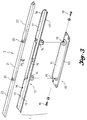
- Fig. 3
- a diagrammatic exploded view of the three-part brake light with the base frame receiving it,
- Fig. 4
- a perspective view of the base frame with the brake light held on this,
- Fig. 5
- 2 shows a perspective view of the base frame with the warning triangle arranged in it and created from the brake light,
- Fig. 6
- partly in view, partly in a vertical section, the arrangement of the base frame with the brake light or the warning triangle behind the rear window of a motor vehicle and
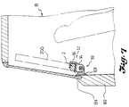
- Fig. 7
- partly in view, partly in a vertical section, the arrangement of the base frame with the brake light or warning triangle behind the rear window of a motor vehicle on its tailgate.
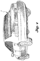
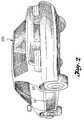
Fig. 1 und 2 zeigen ein Kraftfahrzeug mit der erfindungsgemäß aus einer dreiteiligen Bremsleuchte 2, die in eine Warndreiecksleuchte 200 umwandelbar ist, bestehenden optischen Signaleinrichtung, die innen hinter der Heckscheibe eines Kraftfahrzeugs angebracht ist. In Fig. 1 ist die längliche, stabförmige und dreiteilige dritte Bremsleuchte 2 gezeigt, die beim normalen Fahrbetrieb des Kraftfahrzeugs verwendet wird. Bei einem Defekt am Kraftfahrzeug oder falls dieses aus anderen Gründen unterwegs angehalten werden muß, kann zur Warnung der anderen Kraftfahrzeuge dahinter und zur Erhöhung der Sicherheit des stehenden Kraftfahrzeugs die dreiteilige Bremsleuchte 2 zu einer Warndreiecksleuchte 200 gefaltet werden, die blinken und damit die Aufmerksamkeit erregen kann.1 and 2 show a motor vehicle with the optical signal device, which according to the invention consists of a three-
Die Montage der dreiteiligen Bremdleuchte 2 innen hinter der Heckscheibe eines Kraftfahrzeugs erfolgt mittels eines Grundrahmens 1 (Fig. 3). Der Grundrahmen 1 besteht aus einem Grundhalter 10, einem Träger 12 und einer Stellschraube 19 und kann mit der dreiteiligen Bremsleuchte 2 kombiniert werden. Der Grundhalter 10 und der Träger 12 sind durch Klauen 14 und darin einrastende Zapfen 15 eines Zapfenhalters 11 an dem Grundrahmen 1 gehalten. Eine Halteplatte 101 am Boden des Grundhalters 10 wird zur Montage auf der Befestigungsfläche z. B. der rückwärtigen Hutablage vor der Heckscheibe im Kraftfahrzeuginneren angebracht (Fig. 6). Eine Befestigung ist auch im Heckscheibenbereich an der Heckklappe eines Kraftfahrzeuges möglich (Fig. 7).The three-
Die Bremsleuchte 2 besteht aus drei Teilen, einem mittleren Teil 21 und zwei Seitenteilen 22, die über Scharniere 20 mit dem Mittelteil 21 verbunden sind.The
Der Träger 12 ist als länglicher, stabförmiger Halter mit einem C-und/oder L-förmigen Querschnitt ausgebildet. Die Außenkante der Grundplatte 13 des Trägers 12 weist eine nach oben gerichtete Schutzkante 131 auf. Das Mittelteil des Trägers 12 ist als Klemmstück 16, mit einem C-förmigen Querschnitt ausgebildet, während die beiden äußeren Enden des Trägers Rastungen 17 bilden, deren Querschnitt L-förmig ist. Die Kante der inneren Seitenwand der Rastungen 17 ist mit mehreren Vorsprüngen 18 versehen. Die Klauen 14 rasten in die Zapfen 15 des Zapfenhalters 11 ein und sind in bezug auf die Zapfen drehbar. Weiterhin wird eine Schraube 19 zur Fixierung der Verbindung zwischen den Klauen 14 und den Zapfen 15 verwendet. Die Rastungen 17 werden von hochkant gestellten Abwinkelungen der Grundplatte 13 gebildet und sind nur in den beiden äußeren Seitenbereichen der Grundplatte 13 des Grundrahmens 1 ausgebildet, wobei die beiden äußeren seitenbereiche eine Länge aufweisen, die den beiden Seitenteilen 22 der Bremsleuchte entsprechen, d. h. jeder Seitenbereich entspricht der Länge eines Bremsleuchtenseitenteils 22. Der mittlere Bereich der Grundplatte 13 entspricht der Länge des Mittelteils 21 der Bremsleuchte 2.The
Der mittlere Teil 12 der dreiteiligen Bremsleuchte 2 ist durch das Klemmteil 16 angeklemmt, wobei die beiden Seitenteile 22 der dreiteiligen Bremsleuchte 2 zeitweilig durch die Rastungen 17 mit Hilfe der Vorsprünge 18 und durch die Elastizität der Rastungen 17 selbst gehalten werden. Wie aus Fig. 4 ersichtlich, wird die dreiteilige Bremsleuchte 2 an dem Träger 12 so befestigt, daß ein drittes Bremslicht aus LED gebildet wird. Wird die Warndreiecksleuchte 200 benötigt, werden die beiden Seitenteile 22 der Bremsleuchte 2 nach oben geklappt, so daß die an den freien Enden der Seitenteile 22 der Bremsleuchte 2 vorgesehenen Verbindungsmittel, wie Magnetkörper 23 oder die Teile einer Klettverbindung zusammengeführt werden können, um ein gleichschenkliges Warndreieck zu bilden, das zur Erregung der Aufmerksamkeit blinken kann (Fig. 5). Die beiden Seitenteile 22 der Bremsleuchte 2 können nach ÜBerwinden der federnden Rastung der Vorsprünge 18 und Lösen der Rastungen 17 mit Hilfe von Gelenken 20 eingeklappt werden, und zur Wiederherstellung der dreiteiligen Bremsleuchte 2 können die beiden Seitenteile 22 in die Rastungen 17 gedrückt und so daran befestigt werden. Die Befestigung erfolgt somit vermittels einer federnd-elastischen Klemmverbindung.The
Wie in Fig. 6 dargestellt, wird die Signaleinrichtung auf einer Platte A2 des Rücksitzes innen hinter der Heckscheibe montiert. Der Träger kann drehbar mit dem Grundhalter 10 verbunden und im entsprechenden Winkel passend für verschiedene Kraftfahrzeuge mit unterschiedlicher Heckscheibenneigung eingestellt werden.As shown in Fig. 6, the signal device is mounted on a plate A2 of the rear seat inside behind the rear window. The carrier can be rotatably connected to the
Wie in Fig. 7 dargestellt, ist der Grundrahmen 1 an der Innenseite einer Türplatte B2 innen hinter der Heckscheibe eines Kombi-Fahrzeugs B angebracht. Der Träger 12 ist auf dem Grundhalter 10 in einem Winkel von ca. 90° montiert, so daß die dreiteilige Bremsleuchte 2 von außerhalb der Heckscheibe gesehen werden kann.As shown in Fig. 7, the
Die beiden Seitenteile 22 der Bremsleuchte 2 sind über die Vorsprünge 18 in den Träger 12 federnd eingerastet. Wahlweise kann die Bodenfläche der beiden Seitenteile 22 und die entsprechende Oberfläche der Grundplatte 13 mit Klettbandstreifen (nicht dargestellt) versehen werden, so daß die beiden Seitenteile 22 mit der Grundplatte 13 in auseinandergefaltetem Zustand verbunden werden können, und zur Verwandlung der dreiteiligen Bremsleuchte 2 in eine Warndreiecksleuchte 200 ist dann lediglich das eine Seitenteil und das andere Seitenteil der Bremsleuchte nach oben zu klappen, wobei sie sich von den Klettbandstreifen auf der Grundplatte 13 lösen.The two
Der Grundhalter 10 kann von einer weiteren Ausführungsform, in zwei kleine Grundhalter mit jeweils einer Befestigungsplatte 101 und einem Schwenkhalter 11 sowie einer schwenkbar mit den Klauen 14 verbundenen Zapfenachse 15 unterteilt und an entsprechender Stelle montiert werden.In another embodiment, the
Zusammenfassend stellt die Erfindung einen innen hinter der Heckscheibe montierten Grundrahmen für eine dreiteilige dritte Bremsleuchte dar, die sich in eine Warndreiecksleuchte verwandeln läßt. Der Grundrahmen ist neuartig und praktisch und erweitert das Anwendungsfeld der dreiteiligen dritten Bremsleuchte.In summary, the invention represents a base frame mounted inside the rear window for a three-part third brake light, which can be converted into a warning triangle light. The base frame is new and practical and extends the field of application of the three-part third brake light.
Die Bremsleuchte 2 ist mit einer Anzahl von Lichtquellen versehen, deren Stromversorgung kraftfahrzeugseitig erfolgt, wobei die Betätigung der Bremsleuchte über das Bremspedal erfolgt. Zusätzlich kann die Bremsleuchte 2 noch mit einem LED-Blinklicht versehen sein, wobei auch in diesem Fall die Stromversorgung über die Lichtmaschine oder Batterie des Kraftfahrzeuges erfolgt. Die Bremsleuchte kann zusätzlich für den Gebrauch als Warndreieckleuchte mit einer eigenen Stromversorgung, z. B. in Form von Batterien erfolgen. Bei einer Umrüstung der Bremsleuchte in eine Warndreiecksleuchte wird die über das Bremspedal steuerbare Stromversorgung unterbrochen und diese über die Lichtmaschine oder Batterie selbst vorgenommen, wofür ein Umschalter in der stromzuführenden Leitung vorgesehen ist.The
Claims (7)
Bremsleuchte nach einem der Ansprüche 1 bis 4, dadurch gekennzeichnet, daß die beiden äußeren Teile der dreiteiligen Bremsleuchte (2) mit Klettbandstreifen befestigt sind und an den beiden Seitenteilen des Trägers (12) befestigt und wieder lösbar sind.Brake light according to one of claims 1 to 4, characterized in that the base frame (1) is divided into two smaller base frames, each of which is provided with a mounting plate (101) and a pin holder (11) and a pin axis (15) which can be pivoted with the claw (14) of the carrier (12) is connected and mountable.
Brake light according to one of claims 1 to 4, characterized in that the two outer parts of the three-part brake light (2) are fastened with Velcro strips and on the two side parts of the Carrier (12) attached and releasable.
Priority Applications (1)
| Application Number | Priority Date | Filing Date | Title |
|---|---|---|---|
| EP94107556A EP0683067A1 (en) | 1994-05-16 | 1994-05-16 | Braking lights for vehicle |
Applications Claiming Priority (1)
| Application Number | Priority Date | Filing Date | Title |
|---|---|---|---|
| EP94107556A EP0683067A1 (en) | 1994-05-16 | 1994-05-16 | Braking lights for vehicle |
Publications (1)
| Publication Number | Publication Date |
|---|---|
| EP0683067A1 true EP0683067A1 (en) | 1995-11-22 |
Family
ID=8215948
Family Applications (1)
| Application Number | Title | Priority Date | Filing Date |
|---|---|---|---|
| EP94107556A Withdrawn EP0683067A1 (en) | 1994-05-16 | 1994-05-16 | Braking lights for vehicle |
Country Status (1)
| Country | Link |
|---|---|
| EP (1) | EP0683067A1 (en) |
Cited By (2)
| Publication number | Priority date | Publication date | Assignee | Title |
|---|---|---|---|---|
| EP0818353A2 (en) * | 1996-07-11 | 1998-01-14 | Howard-Lloyde Enterprise Co., Ltd. | Vehicle safety light assembly |
| CN103786638A (en) * | 2014-02-21 | 2014-05-14 | 重庆长安汽车股份有限公司 | Installing structure for high-level braking lamp and back door outer board of automobile |
Citations (3)
| Publication number | Priority date | Publication date | Assignee | Title |
|---|---|---|---|---|
| DE1802834A1 (en) * | 1968-10-12 | 1970-06-11 | Wolany Kg Zufor Ind Masch | Warning triangle |
| US4825191A (en) * | 1986-07-29 | 1989-04-25 | Ching Hwei Lan | Automobile multi-purpose auxiliary indicator |
| US5126926A (en) * | 1991-09-27 | 1992-06-30 | Chiang Chiang Wen | Brake-light/hazard-warning board structure |
-
1994
- 1994-05-16 EP EP94107556A patent/EP0683067A1/en not_active Withdrawn
Patent Citations (3)
| Publication number | Priority date | Publication date | Assignee | Title |
|---|---|---|---|---|
| DE1802834A1 (en) * | 1968-10-12 | 1970-06-11 | Wolany Kg Zufor Ind Masch | Warning triangle |
| US4825191A (en) * | 1986-07-29 | 1989-04-25 | Ching Hwei Lan | Automobile multi-purpose auxiliary indicator |
| US5126926A (en) * | 1991-09-27 | 1992-06-30 | Chiang Chiang Wen | Brake-light/hazard-warning board structure |
Cited By (4)
| Publication number | Priority date | Publication date | Assignee | Title |
|---|---|---|---|---|
| EP0818353A2 (en) * | 1996-07-11 | 1998-01-14 | Howard-Lloyde Enterprise Co., Ltd. | Vehicle safety light assembly |
| EP0818353A3 (en) * | 1996-07-11 | 1998-10-21 | Howard-Lloyde Enterprise Co., Ltd. | Vehicle safety light assembly |
| CN103786638A (en) * | 2014-02-21 | 2014-05-14 | 重庆长安汽车股份有限公司 | Installing structure for high-level braking lamp and back door outer board of automobile |
| CN103786638B (en) * | 2014-02-21 | 2015-11-18 | 重庆长安汽车股份有限公司 | The mounting structure of High-Position Automotive Brake Lights and tailgate outside plate |
Similar Documents
| Publication | Publication Date | Title |
|---|---|---|
| DE102010017182A1 (en) | Bicycle carrier of a vehicle | |
| DE102019124081B3 (en) | Device and method for securing a screen arrangement for a vehicle roof and vehicle roof for a motor vehicle | |
| DE29712954U1 (en) | License plate for a motor vehicle | |
| DE9411780U1 (en) | Brake light for motor vehicles | |
| DE3525198A1 (en) | LIGHT UNIT | |
| EP0683067A1 (en) | Braking lights for vehicle | |
| EP0083769A2 (en) | Rear view mirror device for a vehicle | |
| DE1807293A1 (en) | Additional device for a vehicle exterior mirror | |
| DE10009971A1 (en) | Carrier system especially for carrying bicycle on back of motor vehicle has base support with rearwards extendable body section, the extension of which is effected by two double links extending in scissor fashion | |
| EP0190715A1 (en) | Vehicle swing door | |
| DE102010017158A1 (en) | Additional device of a carrier of a vehicle | |
| DE2838525A1 (en) | High visibility car rear view mirror - includes additional sprung mirror for viewing rear seat occupants | |
| DE3631578C1 (en) | Roof sign for vehicles, in particular passenger vehicles | |
| DE19739172A1 (en) | Assembly system for motor vehicle roof with hingeable flat element | |
| EP0904980A2 (en) | Attachment device for a flashing light | |
| DE2845446A1 (en) | Extending towing mirror on vehicle - has outward sliding mirror unit mounted in moulded guides with lock=nut | |
| EP1262371B1 (en) | Publicity carrier for vehicle roof | |
| DE2611922A1 (en) | Banner fixed across car roof to give warning of breakdown - comprises pref. dark coloured PVC with a light reflecting plastic symbol | |
| DE1802834A1 (en) | Warning triangle | |
| DE2751878A1 (en) | External rear view driving mirror - has upper and lower sections with separate housings rotated relative to each other to provide desired field of view | |
| DE2209952A1 (en) | TRIPLE REVIEW - CAR SCREEN THROUGH SHOOTING TELEVISIONS OR OTHER OPTICAL LENSES OR EYES WITH RECEIVING DEVICE, AND METHOD OF MANUFACTURING | |
| DE887748C (en) | Dimming device for motor vehicles | |
| DE2357287C3 (en) | Rearview mirrors for vehicles, in particular for passenger cars | |
| WO2021069726A1 (en) | Device for securing an optical device | |
| DE893898C (en) | Rearview device, especially for vehicles |
Legal Events
| Date | Code | Title | Description |
|---|---|---|---|
| PUAI | Public reference made under article 153(3) epc to a published international application that has entered the european phase |
Free format text: ORIGINAL CODE: 0009012 |
|
| AK | Designated contracting states |
Kind code of ref document: A1 Designated state(s): AT BE DE ES FR GB IT NL SE |
|
| 17P | Request for examination filed |
Effective date: 19960708 |
|
| 17Q | First examination report despatched |
Effective date: 19970703 |
|
| GRAG | Despatch of communication of intention to grant |
Free format text: ORIGINAL CODE: EPIDOS AGRA |
|
| STAA | Information on the status of an ep patent application or granted ep patent |
Free format text: STATUS: THE APPLICATION HAS BEEN WITHDRAWN |
|
| 18W | Application withdrawn |
Withdrawal date: 19970925 |