EP0683017A1 - Robot hand for forging working - Google Patents
Robot hand for forging working Download PDFInfo
- Publication number
- EP0683017A1 EP0683017A1 EP94107614A EP94107614A EP0683017A1 EP 0683017 A1 EP0683017 A1 EP 0683017A1 EP 94107614 A EP94107614 A EP 94107614A EP 94107614 A EP94107614 A EP 94107614A EP 0683017 A1 EP0683017 A1 EP 0683017A1
- Authority
- EP
- European Patent Office
- Prior art keywords
- grip
- hand
- casing
- robot hand
- guide
- Prior art date
- Legal status (The legal status is an assumption and is not a legal conclusion. Google has not performed a legal analysis and makes no representation as to the accuracy of the status listed.)
- Granted
Links
- 238000005242 forging Methods 0.000 title description 28
- 229920001971 elastomer Polymers 0.000 claims description 19
- 239000000806 elastomer Substances 0.000 claims description 18
- 230000007935 neutral effect Effects 0.000 claims description 14
- 230000002093 peripheral effect Effects 0.000 claims description 9
- 238000006073 displacement reaction Methods 0.000 claims description 6
- 239000012530 fluid Substances 0.000 description 9
- 239000000463 material Substances 0.000 description 8
- 230000009471 action Effects 0.000 description 2
- 230000003139 buffering effect Effects 0.000 description 2
- 239000004033 plastic Substances 0.000 description 2
- 229920006311 Urethane elastomer Polymers 0.000 description 1
- 238000005452 bending Methods 0.000 description 1
- 238000006243 chemical reaction Methods 0.000 description 1
- 230000010485 coping Effects 0.000 description 1
- 230000001788 irregular Effects 0.000 description 1
- 230000007246 mechanism Effects 0.000 description 1
- 230000004048 modification Effects 0.000 description 1
- 238000012986 modification Methods 0.000 description 1
- 238000009497 press forging Methods 0.000 description 1
- 230000004044 response Effects 0.000 description 1
Images


Classifications
-
- B—PERFORMING OPERATIONS; TRANSPORTING
- B21—MECHANICAL METAL-WORKING WITHOUT ESSENTIALLY REMOVING MATERIAL; PUNCHING METAL
- B21J—FORGING; HAMMERING; PRESSING METAL; RIVETING; FORGE FURNACES
- B21J13/00—Details of machines for forging, pressing, or hammering
- B21J13/08—Accessories for handling work or tools
-
- B—PERFORMING OPERATIONS; TRANSPORTING
- B25—HAND TOOLS; PORTABLE POWER-DRIVEN TOOLS; MANIPULATORS
- B25J—MANIPULATORS; CHAMBERS PROVIDED WITH MANIPULATION DEVICES
- B25J17/00—Joints
- B25J17/02—Wrist joints
- B25J17/0208—Compliance devices
-
- B—PERFORMING OPERATIONS; TRANSPORTING
- B25—HAND TOOLS; PORTABLE POWER-DRIVEN TOOLS; MANIPULATORS
- B25J—MANIPULATORS; CHAMBERS PROVIDED WITH MANIPULATION DEVICES
- B25J9/00—Programme-controlled manipulators
- B25J9/10—Programme-controlled manipulators characterised by positioning means for manipulator elements
- B25J9/1005—Programme-controlled manipulators characterised by positioning means for manipulator elements comprising adjusting means
- B25J9/1015—Programme-controlled manipulators characterised by positioning means for manipulator elements comprising adjusting means using additional, e.g. microadjustment of the end effector
Definitions
- the present invention relates to a robot hand for forging which is capable of carrying out forging using a robot, in particular die forging performed on a die having a plurality of stamping impressions hereon as well as hammer forging, and press forging, and in particular to a robot which can protect a robot hand per se and a robot main body by reducing an impact occurring on hammering, and is capable of a accurately positioning of a workpiece to be forged on each of stamping impressions.
- Die forging using a hammer generates impacts and vibrations since it involves deforming material to be forged with impact energy. It is difficult to stably hold the material to be forged with a conventional robot or manipulator.
- Deformation of blank material and the shape of resulting burrs is irregular and in particular, a gripped portion of the material to be forged is irregularly deformed.
- die forging in which forging is carried out for each of the stamping impressions after the material is successively moved relative to each of a plurality of stamping impressions on a die, a robot is unable to accurately load the material to be forged on next stamping impression of the die due to changes in relative position between the robot hand and the material which is subject to plastic deformation.
- Such forging has heretofore been conducted by manually holding workpieces to be forged.
- the present invention was made to overcome the above mentioned problems.
- a robot hand for gripping a workpiece to be forged comprising a grip hand for gripping said workpiece to be forged; and a grip hand support for supporting the grip hand so that the grip hand is movable in a desired direction in an imaginary plane, inclinable in a desired direction in a three-dimensional space around a point on the imaginary plane as a center, movable in an axial direction of the grip hand, and rotatable around an axis;
- the grip hand including a plurality of fingers for gripping the workpiece to be forged; and a grip body having one end thereof on which the fingers are movably mounted;
- the grip hand support including a casing into which the other end portion of the grip body is inserted; support means disposed in the casing for supporting the other end portion of the grip body so that the grip hand is movable, inclinable and rotatable relative to the casing; and supporting state changing means for changing the supporting states among a displacement changing state, in which the
- imaging plane means a plane which is perpendicular to the axis of the grip guide and corresponds to a plane which is taken along a line A-A in Fig. 1.
- the spherical surface and the spherical bearing seat formed in a grip guide which will be described hereafter are moved in a radial direction (in a desired direction of said imaginary plane).
- hydraulic actuator(s) used herein also includes “pneumatic actuator(s)”.
- the support means of the robot hand may preferably comprise a grip guide to which the other end portion of the grip body is inserted, a part of the outer periphery of which is formed with a spherical surface, for supporting the grip body so that it is movable in an axial direction thereof; and a spherical seat which is in contact with the spherical surface of the grip guide for bearing the same so that the grip guide is inclinable in a desired direction within a three dimension space around a point on the imaginary plane; the casing being assumed of the imaginary plane which is perpendicular to the axis of the casing, the grip guide into which the grip body is inserted and the spherical seat for supporting the grip guide being movable in the imaginary plane.
- the supporting state changing means may preferably include a hydraulic actuator having a piston which is displaceable in an axial direction of the grip body between the movement constraining position, in which the front end portion of the piston is in contact with the grip body (end face opposite to the fingers and a movement enabling position, in which the front end portion of the piston is not in contact with the grip body.
- the supporting state changing means preferably further includes a hydraulic actuator having a piston which is capable of biasing at the front end thereof toward the outer periphery of the grip body via the brake liner for constraining the axial movement between the grip guide and the grip body.
- the supporting state changing means preferably includes three or more hydraulic actuators each having a piston which is movable in said imaginary plane between a movement constraining position, in which the front end portion of the piston is in contact with said spherical seat and a movement enabling position, in which the front end portion thereof is not in contact with said spherical seat.
- the supporting state changing means preferably includes three or more hydraulic actuators in positions remote from the spherical surface on the grip guide, each having a piston which is movable between an inclination constraining position, in which the front end portion of the piston is in contact with said grip guide and an inclinable position in which the front end portion of the piston is not in contact with said grip guide to return the inclination of the grip guide to the initial neutral (horizontal) position.
- the spherical bearing saet is divided into two parts disposed in front and to the rear of the imaginary plane assumed in the casing. A small space is formed between the divided spherical bearing seat halves.
- a ring-piston type hydraulic actuator is preferably provided adjacent to the spherical bearing seat.
- a hydraulic actuator having a piston for biasing the spherical bearing seat halves toward the imaginary plane (in an axial direction). The hydraulic actuators sandwich therebetween a spherical surface with two divided spherical bearing seat halves to hold the grip guide while it is moved in a desired direction in the imaginary plane and simultaneously to hold the grip guide while it is inclined in a desired position.
- a space is formed between the inner edges of the spherical bearing seat halves. It is preferable to fill the space with elastomer such as rubber to provide a function to keep constant position of the grip hand with a frictional force between the elastomer and the halves even if a hydraulic pressure is not applied upon said ring piston. Maintaining of the grip hand in a constant position can be achieved even if the biasing force of the spherical bearing seat halves is reduced by controlling the hydraulic pressure of the ring piston in lieu of filling the space with elastomer.
- elastomer such as rubber
- a robot having the above mentioned robot hand may preferably include a robot hand support for rotating the robot hand around an axis of the grip support of the robot hand.
- a robot hand for gripping a workpiece to be forged comprising a grip for gripping the workpiece to be forged; and a grip support for supporting the grip so that the grip is movable in directions parallel with and rotatable around three independent axes which are perpendicular to each other in a three-dimensional space and is movable in a resultant direction of two or three axis;
- the grip including a plurality of fingers for gripping the workpiece to be forged; and a grip body having one end thereof on which the fingers are movably mounted;
- the grip support including a casing into which the other end portion of the grip body is inserted; support means disposed in the casing for supporting the other end portion of the grip body so that the grip is movable and rotatable relative to the casing; and supporting state changing means for changing the state among a displacement enabling state in which the grip is movable and/or rotatable relative to the casing when an external force is applied to the grip which grips the workpiece to be
- the support means of the robot hand may comprise a grip guide to which the other end portion of the grip body is inserted, a part of the outer periphery of which is formed with a spherical surface, for supporting the grip body so that it is movable in a direction of any of the three axes; and a spherical seat which is in contact with the spherical surface of the grip guide for bearing the same so that the grip guide is rotatable around the three axes; wherein, said casing being formed in such a manner that said grip guide to which the grip body is inserted and the spherical seat for bearing the grip guide are movable within the casing.
- Operation of the present invention is as follows:
- the robot hand of the present invention grips one end (gripped portion) of the blank workpiece to load the workpiece between upper and lower dies of a forging machine. Even if the gripped portion of the workpiece is displaced due to plastic deformation of the workpiece, the impact deformation is absorbed by movement of the hand in a desired direction, its inclination and/or rotation in a three-dimensional space for protecting the robot hand per se and main body of the robot. Accurate movement of the blank workpiece on a stamping impression is enabled by holding the workpiece in the displaced position with hydraulic pressure.
- a robot of the present embodiment is adapted to grip a blank workpiece W to be forged at one end thereof along the length thereof for facilitating the forging as shown in Fig. 1.
- a robot arm 1 (Fig. 3) is movably mounted on the main body (not shown) of the robot.
- the robot arm 1 is provided with a robot hand 2 at the front end thereof.
- the robot hand 2 comprises a grip hand 3 for directly gripping the blank workpiece W at one end of the workpiece along the length thereof and a grip support 2a into which the rear portion of the grip hand 3 is inserted for supporting the grip hand 3.
- the grip support 2a is opened at the front end thereof and is hollow in shape.
- the grip support 2 is provided therein with a mechanism for holding the rear side portion of the grip hand 3 so that the grip hand 3 is vertically and laterally movable and can be inclined.
- the rear side portion of the grip hand 3 is formed in such a manner that it is held so as to be forwardly or backwardly movable.
- An inner chamber of the grip support 2a and the rear portion of the grip hand 3 constitute a buffer portion for buffering the impact vibrations of the grip hand 3 which occur due to hammering during forging.
- the buffering portion reduces or mitigates the impact on hammering to protect the robot hand 2 per se and the robot main body of the robot and enables accurate movement of the workpiece to the stamping impressions by following the displacement of the grip hand 3 which grips the workpiece W.
- the grip support 2a includes an outer cylinder 4 which is hollow therein and is opened at the front end thereof.
- a spherical bearing seat 5 is held on the inner periphery of the open end portion of the outer cylinder 4 so that the spherical bearing seat 5 is movable in vertical and lateral directions.
- the spherical bearing seat 5 is adapted to support or bear the spherical surface 13 which is formed on the front portion of the grip guide 12 which will be described hereafter.
- the spherical bearing seat 5 is annular in shape and the inner annular peripheral surface thereof functions as a spherical bearing seat.
- the annular spherical bearing seat 5 includes spherical bearing seat halves 5a and 5b which are in front and rear positions in an axial direction. A slight gap is formed between the facing surfaces of the spherical bearing seat halves 5a and 5b along the outer edges thereof. A space is formed between the spherical bearing seat halves 5a and 5c in a radial direction from the insides thereof to the inner edges thereof and is filled with an annular elastomer 5c.
- the elastomer 5c functions to bias the front and rear spherical bearing seat halves 5a, 5b upon a ring piston 7 and a guide 6 by its spring force for preventing the spherical bearing seat halves from moving in vertical and lateral directions with its frictional force.
- the elastomer 5c may be, for example, urethane rubber.
- the elastomer 5c is in contact with the spherical surface 13 of the grip guide 12 at the inner peripheral surface thereof to prevent the grip guide 12 from inclining by its frictional resistance. Even if no hydraulic pressure is applied to the ring piston 7 which will be described hereafter, the elastomer 5c serves to maintain the grip hand 3 at a constant position. Since the above mentioned constraint is due to the frictional force of the elastomer 5c, the spherical bearing seat halves 5a, 5b and the grip guide 12 would be displaced or inclined if an impact force which is larger than this frictional force is applied to the grip hand 3.
- a guide 6 which is in contact with the rear side of the annular spherical bearing seat 5 to constrain it, is provided on the inner peripheral surface of the inner wall of the outer cylinder 4 on the opening side thereof.
- the guide 6 is formed along the inner periphery of the outer cylinder 4 and projects therefrom in an inner radial direction thereof.
- the ring piston 7 is mounted on the peripheral edge portion 8 of the opening of the outer cylinder 4, which is located in front of the guide 6 and biases the front side of the annular spherical bearing seat 5 to the guide 6.
- the annular spherical bearing seat 5 is sandwiched on the front and rear sides thereof between the ring piston 7 and the guide 6 so that it is held in position.
- the ring piston 7 is arranged so that its biasing force upon the spherical bearing seat 5 is controlled with fluid pressure.
- the elastomer 5c may be omitted, for example, by making the hydraulic pressure applied upon the ring piston 7 changeable between high and low levels and by lowering the biasing force of the ring piston 7 to a force corresponding to the above mentioned elastic force of the elastomer 5c.
- Center returning actuators 9 each including a hydraulic or pneumatic actuator or the like are adapted to return the vertically and/or laterally displaced spherical bearing seat 5 to a neutral position in vertical and lateral directions.
- a total of at least 3, center returning actuators 9 (four actuators in this embodiment) are provided at angles of 90° in the outer cylinder 4 between the ring piston 7 and the guide 6.
- Each of the center returning actuators 9 includes a piston which is movable in a plane perpendicular to a forward or rearward direction.
- Each center returning actuator 9 is mounted in such a manner that at the front end of the piston of each center returning actuator 9 biases the outer peripheral surface of the spherical bearing seat 5 in an inner radial direction within the outer cylinder 4.
- Each center returning actuator 9 is controlled with hydraulic pressure. When supply of the hydraulic fluid to the center returning actuator 9 ceases, the piston is retracted.
- Inclination returning actuators 10 each including a hydraulic or pneumatic actuator or the like are adapted to return the inclined grip hand 3 to an original horizontal position.
- a total of at least 3 (4 in this embodiment) inclination returning actuators 10 are provided at angles of 90° in the outer cylinder 4 which is to the rear of the guide 6.
- Each of the inclination returning actuators 10 includes a piston which is movable in a plane perpendicular to a forward or rearward direction.
- Each inclination returning actuator 10 is mounted in such a manner that the front end of the piston of the inclination returning actuator 10 biases a grip guide 12 which is fitted on the rear portion of the grip hand 3 in an inner radial direction within the outer cylinder 4.
- Each inclination returning actuator 10 is controlled with hydraulic pressure. When supply of the hydraulic fluid to the center returning actuator 10 ceases, the piston is retracted.
- a forward returning actuator 11 including a hydraulic or pneumatic actuator or the like is adapted to return the axially displaced grip hand 3 to an original forward position and is provided within the outer cylinder 4 at the rear end thereof.
- the forward returning actuator 11 includes a piston which is axially movable.
- the forward returning actuator 11 is mounted in such a manner that the front end of the forward returning actuator 11 biases the rear end of the grip hand 3 in a forward direction.
- the forward returning actuator 11 is controlled with hydraulic pressure. When supply of the hydraulic fluid to the forward returning actuator 11 ceases, the piston is retracted.
- the grip hand 3 includes a plurality of fingers 3a for gripping a workpiece, a grip body 3b for supporting the plurality of fingers 3a so that they are movable, and a piston 3c which moves to operate the plurality fingers 3a for gripping the blank workpiece forwards or backwards within the grip body 3b.
- the grip guide 12 is fitted to the rear portion of the grip hand 3. Specifically, the grip guide 12 is formed with a hole 12a therein into which the rear portion of the grip hand 3 is fitted so that the grip hand 3 is axially movable.
- the grip hand 3 is formed on the outer periphery thereof at the rear end thereof with a stopper 3d which projects in an outer radial direction. This stopper 3d serves to prevent the grip guide 12 from being removed from the rear end of the grip hand 3.
- the grip guide 12 is formed on the outer surface thereof on the front side thereof with a spherical surface 13 which is seated on the above mentioned spherical bearing seat 5 so that the grip guide 12 can be inclined.
- the outer peripheral surface of the grip guide 12 on the rear side which is in contact with the front ends of the pistons of the inclination returning actuators 10 is formed into flat surfaces 12b.
- the number of flat surfaces 12b is equal to the number of inclination returning actuators 10.
- a brake liner 14 is provided on the inner periphery of the hole 12a which is on the rear side of the grip guide 12.
- a piston 15 for biasing the brake liner 14 is disposed on the outer side of the brake liner 14 at the rear end of the grip guide 12. The piston 15 can bias upon the outer periphery of the grip body via the liner 14 for preventing the grip body from moving in an axial direction thereof.
- a cotter 16 is provided between the hole 12a and the grip hand 3 to prevent relative rotation therebetween and to allow forward and rearward movement thereof.
- the spherical surface 13 of the grip guide 12 is seated on the spherical bearing seat 5. Accordingly, the grip guide 12 and the grip hand 3 which is fitted on the guide 12 are afforded universal inclination and rotation.
- the spherical bearing seat 5 which bears the spherical surface 13 of the grip guide 12 is divided into axially front and rear halves which are separated from each other on the facing sides thereof to form a slight gap.
- the front spherical bearing seat half 5a is biased backwardly by the ring piston 7 incorporated in the outer cylinder 4 to bias via the elastomer 5c and the spherical surface 13 of the grip guide 12 the rear spherical bearing seat half 5b upon the guide 6 which is the front portion of the outer cylinder 4 (a plane which is perpendicular to the axis of the cylinder 4).
- the elastomer 5c may be omitted by making the fluid pressure on the ring piston 7 adjustable. In lieu of one annular ring piston 7, several pistons may be disposed at equal angular spaces.
- Two front and rear spherical bearing seat halves 5a and 5b sandwich therebetween the spherical surface 13 of the grip guide 12 to suppress the free movement of the grip guide 12 with its frictional force to hold rotation or inclination of the grip guide 12 in a desired position.
- the spherical bearing seat 5, the grip guide 12 and the grip hand 3 can be held in a desired position with the frictional force caused due to the biasing force of the ring piston 7 without being slid downward.
- the spherical bearing seat 5, that is, the grip hand 3 would be moved in a vertical or lateral direction, respectively, or the spherical surface 13, that is, the grip hand 3 may be inclined around the spherical bearing seat 5 which functions as a fulcrum.
- Three or more center returning actuators 9 are disposed at equal angular spaces (a total of four actuators at angular 90° spaces in the present embodiment) in the outer cylinder 4 which is the opposite side of the spherical bearing seat 5.
- the spherical bearing seat 5 is biased in an inner radial direction from the outer side thereof by the pistons of the center returning actuators 9.
- This arrangement enables the vertically or laterally displaced spherical bearing seat 5 to be returned to the initial neutral position.
- the vertically or laterally displaced grip hand 3 can be biased so that it is returned to the center axis of the outer cylinder 4.
- the spherical bearing seat 5 and the grip hand 3 can be positioned in the center, or the neutral position of the outer cylinder 4.
- the rear portion of the grip guide 12 can be biased to return to the center of the outer cylinder 4 by three or more inclination returning actuators 10 which are disposed at equal angular spaces in the outer cylinder 4 which is on the rear side and on the outer periphery of the grip guide 12.
- the rear portion of the grip guide 12 is positioned centrally of the outer cylinder 4. Accordingly, the grip guide 12 and the grip hand 3 can be positioned in the initial horizontal position by the mutual reaction between the center returning actuators 9 and the inclination returning actuators 10.
- the flat surfaces 12b which are as many as the inclination returning actuators 10, are provided on the outer periphery of the grip guide 12. By biasing the front ends (flattened) of the pistons of the inclination returning actuators 10 on the flat surfaces 12h, the displaced grip hand 3 can be returned to the initial neutral or home position.
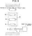
- a die 30 is formed with a plurality of stamping impressions 31, 32, 33 for the workpiece W as shown in Fig. 5.
- hydraulic fluid is supplied to the actuators provided in the grip support 2a to position the grip hand 3 in the initial position for aligning the axis of the robot arm 1 with the axis of the grip hand 3.
- the grip hand 3 is flexibly displaced relative to the outer cylinder 4 of the grip support 2a.
- the central axis of the grip hand 3 that is the center of the workpiece W, may be offset in a vertical direction from the center of the robot arm 1 (for example, offset by Y as shown in Fig. 3). If the workpiece W is deformed by hammering or application of a pressure under this condition, the position of the grip hand 3 is changed from that under predetermined conditions (for example, it changes to a condition of Fig. 4).
- the position of the grip hand 3 is maintained by applying a pressure to the ring piston 7.
- maintaining of the position of the grip hand 3 is achieved by increasing the friction between the spherical bearing seat half 5b and the guide 6 and the friction between the spherical bearing seat halves 5a, 5b and the spherical surface 13 of the grip guide 12 by applying a pressure on the piston ring 7, or alternatively by increasing the friction between the grip hand 3d and the brake liner 14 by applying a pressure upon the piston 15.
- central axis of the robot arm 1 is always aligned with the central axis of the stamping impression of the die, accurate loading on next stamping impression can be made with reference to the central axis of the robot arm 1 whenever the grip hand 3 is deformed in any way due to deformation of the gripped portion of the workpiece W.
- the grip hand 3 In the case of forging which requires movement of a workpiece to a plurality of stamping impressions, on starting of forging, the grip hand 3 is in a given neutral position with four center returning actuators 9 disposed around the grip hand 3, the inclination returning actuators 10 and the forward returning actuator 11 which is provided in rear of the cylinder 4.
- the spherical bearing seat 5 and the brake liner 14 are biased upon the grip hand 3 by the ring piston 7 and the piston 15 which are actuated by the hydraulic pressure so that the position of the grip hand 3 is maintained. Under this condition, the workpiece W is gripped and is loaded in position on the first stamping impression 31 between upper and lower dies.
- the grip hand 3 When introducing of fluid into the center returning actuators 9, the inclination returning actuators 10, the forward returning actuator 11, the ring piston 7 and the piston 15 is stopped, the grip hand 3 is held with a small holding force caused by only the friction between the supporting spherical surface 13 of the grip guide 12 and the elastomer 5c. Although the grip hand 3 is held in a neutral position under this condition, it can be freely displaced in response to an external force which is generated by forging impact.
- the central axis of the robot arm 1 is aligned with the central axis of the die stamping impression.
- the robot arm 1 is moved to the next stamping impression. If the central axis of next robot arm 1 is aligned with the central axis of the die stamping impression 32, the workpiece W can be accurately loaded on the next stamping impression 32 no matter how the position and orientation of the grip hand 3 is changed.
- the robot is returned to a position where it will grip the next workpiece W.
- the returning step supply of the hydraulic pressure to the ring piston 7 and the piston 15 is stopped and the grip hand 3 is returned to a given neutral position by operating four center returning actuators 9 provided around the grip hand 3, the inclination returning actuators 10 and the froward returning actuator 11 which is provided in the rear of the outer cylinder 4 in a proper timing relationship.
- a bearing 17 and a flange 18 are provided in the rear of the outer cylinder 4 of the robot hand 2 and a motor 19 may be mounted on the flange 18, which is then mounted on the robot arm 1.
- the whole of the robot hand that is, the workpiece W can be rotated by rotating the outer cylinder 4 of the robot hand 2 with an output shaft of the motor.
- Products which are bent in a horizontal direction can be forged.
- the grip hand 3 which is universally displaced to absorb the impacts occurring on forging even if forging is conducted while the robot hand grips the workpiece W since the grip hand is provided with a spherical bearing seat and linear guide which enable the hand to be moved in any direction.
- the forging period of time can be shortened since rehandling of the workpiece is not required whenever the workpiece is successively moved between stamping impressions in the case of forging using a die having a plurality of stamping impressions.
Landscapes
- Engineering & Computer Science (AREA)
- Mechanical Engineering (AREA)
- Robotics (AREA)
- Manipulator (AREA)
Abstract
Description
- The present invention relates to a robot hand for forging which is capable of carrying out forging using a robot, in particular die forging performed on a die having a plurality of stamping impressions hereon as well as hammer forging, and press forging, and in particular to a robot which can protect a robot hand per se and a robot main body by reducing an impact occurring on hammering, and is capable of a accurately positioning of a workpiece to be forged on each of stamping impressions.
- There is not known a robot hand which is capable of suitably coping with deformation of material due to impacts, vibrations and hammering occurring in association with die forging especially performed on a die having a plurality of stamping impressions using a hammer.
- Die forging using a hammer generates impacts and vibrations since it involves deforming material to be forged with impact energy. It is difficult to stably hold the material to be forged with a conventional robot or manipulator.
- Deformation of blank material and the shape of resulting burrs is irregular and in particular, a gripped portion of the material to be forged is irregularly deformed. In die forging in which forging is carried out for each of the stamping impressions after the material is successively moved relative to each of a plurality of stamping impressions on a die, a robot is unable to accurately load the material to be forged on next stamping impression of the die due to changes in relative position between the robot hand and the material which is subject to plastic deformation. Such forging has heretofore been conducted by manually holding workpieces to be forged.
- The present invention was made to overcome the above mentioned problems.
- It is an object of the present invention to provide a robot hand for forging which relaxes or mitigates the impacts on hammering or pressing for protecting the robot hand per se and the main body of the robot, and which is capable of freely following the displacement of a gripped portion of a workpiece and is capable of accurately moving the workpiece on stamping impressions.
- In order to accomplish the above mentioned object of the present invention, there is provided a robot hand for gripping a workpiece to be forged comprising a grip hand for gripping said workpiece to be forged; and a grip hand support for supporting the grip hand so that the grip hand is movable in a desired direction in an imaginary plane, inclinable in a desired direction in a three-dimensional space around a point on the imaginary plane as a center, movable in an axial direction of the grip hand, and rotatable around an axis; the grip hand including a plurality of fingers for gripping the workpiece to be forged; and a grip body having one end thereof on which the fingers are movably mounted; the grip hand support including a casing into which the other end portion of the grip body is inserted; support means disposed in the casing for supporting the other end portion of the grip body so that the grip hand is movable, inclinable and rotatable relative to the casing; and supporting state changing means for changing the supporting states among a displacement changing state, in which the grip hand is movable, inclinable and rotatable relative to the casing when an external force is applied to the grip hand gripping the workpiece to be forged; a constraining state in which the grip hand, which is displacable relative to the casing, is constrained to make it movement, inclination and rotation impossible unless an external force which is not less than a predetermined force is applied to the grip hand; and an initial neutral position constraining state in which the grip hand which has been displaced relative to the casing is returned to a predetermined initial neutral position and the movement, inclination and rotation of the grip hand is constrained to make its movement, inclination and rotation impossible in the initial neutral position.
- A term "imaginary plane" means a plane which is perpendicular to the axis of the grip guide and corresponds to a plane which is taken along a line A-A in Fig. 1. The spherical surface and the spherical bearing seat formed in a grip guide which will be described hereafter are moved in a radial direction (in a desired direction of said imaginary plane).
- It is to be understood that a term "hydraulic actuator(s)" used herein also includes "pneumatic actuator(s)".
- The support means of the robot hand may preferably comprise a grip guide to which the other end portion of the grip body is inserted, a part of the outer periphery of which is formed with a spherical surface, for supporting the grip body so that it is movable in an axial direction thereof; and a spherical seat which is in contact with the spherical surface of the grip guide for bearing the same so that the grip guide is inclinable in a desired direction within a three dimension space around a point on the imaginary plane; the casing being assumed of the imaginary plane which is perpendicular to the axis of the casing, the grip guide into which the grip body is inserted and the spherical seat for supporting the grip guide being movable in the imaginary plane.
- In this case, the supporting state changing means may preferably include a hydraulic actuator having a piston which is displaceable in an axial direction of the grip body between the movement constraining position, in which the front end portion of the piston is in contact with the grip body (end face opposite to the fingers and a movement enabling position, in which the front end portion of the piston is not in contact with the grip body.
- The supporting state changing means preferably further includes a hydraulic actuator having a piston which is capable of biasing at the front end thereof toward the outer periphery of the grip body via the brake liner for constraining the axial movement between the grip guide and the grip body.
- The supporting state changing means preferably includes three or more hydraulic actuators each having a piston which is movable in said imaginary plane between a movement constraining position, in which the front end portion of the piston is in contact with said spherical seat and a movement enabling position, in which the front end portion thereof is not in contact with said spherical seat.
- The supporting state changing means preferably includes three or more hydraulic actuators in positions remote from the spherical surface on the grip guide, each having a piston which is movable between an inclination constraining position, in which the front end portion of the piston is in contact with said grip guide and an inclinable position in which the front end portion of the piston is not in contact with said grip guide to return the inclination of the grip guide to the initial neutral (horizontal) position.
- The spherical bearing saet is divided into two parts disposed in front and to the rear of the imaginary plane assumed in the casing. A small space is formed between the divided spherical bearing seat halves. A ring-piston type hydraulic actuator is preferably provided adjacent to the spherical bearing seat. A hydraulic actuator having a piston for biasing the spherical bearing seat halves toward the imaginary plane (in an axial direction). The hydraulic actuators sandwich therebetween a spherical surface with two divided spherical bearing seat halves to hold the grip guide while it is moved in a desired direction in the imaginary plane and simultaneously to hold the grip guide while it is inclined in a desired position.
- A space is formed between the inner edges of the spherical bearing seat halves. It is preferable to fill the space with elastomer such as rubber to provide a function to keep constant position of the grip hand with a frictional force between the elastomer and the halves even if a hydraulic pressure is not applied upon said ring piston. Maintaining of the grip hand in a constant position can be achieved even if the biasing force of the spherical bearing seat halves is reduced by controlling the hydraulic pressure of the ring piston in lieu of filling the space with elastomer.
- A robot having the above mentioned robot hand may preferably include a robot hand support for rotating the robot hand around an axis of the grip support of the robot hand.
- Further, there is provided a robot hand for gripping a workpiece to be forged comprising a grip for gripping the workpiece to be forged; and a grip support for supporting the grip so that the grip is movable in directions parallel with and rotatable around three independent axes which are perpendicular to each other in a three-dimensional space and is movable in a resultant direction of two or three axis; the grip including a plurality of fingers for gripping the workpiece to be forged; and a grip body having one end thereof on which the fingers are movably mounted; the grip support including a casing into which the other end portion of the grip body is inserted; support means disposed in the casing for supporting the other end portion of the grip body so that the grip is movable and rotatable relative to the casing; and supporting state changing means for changing the state among a displacement enabling state in which the grip is movable and/or rotatable relative to the casing when an external force is applied to the grip which grips the workpiece to be forged; a constraining state, in which the grip is constrained to make movement and rotation impossible unless an external force which is not less than predetermined force is applied to the grip after the grip of moved and/or rotated relative to the casing; an initial position constraining state in which the grip is returned to a predetermined initial position relative to the casing and is constrained in the initial position to prevent its movement and rotation even if the grip is moved and/or rotated relative to the casing.
- The support means of the robot hand may comprise a grip guide to which the other end portion of the grip body is inserted, a part of the outer periphery of which is formed with a spherical surface, for supporting the grip body so that it is movable in a direction of any of the three axes; and a spherical seat which is in contact with the spherical surface of the grip guide for bearing the same so that the grip guide is rotatable around the three axes; wherein, said casing being formed in such a manner that said grip guide to which the grip body is inserted and the spherical seat for bearing the grip guide are movable within the casing.
- Operation of the present invention is as follows:
The robot hand of the present invention grips one end (gripped portion) of the blank workpiece to load the workpiece between upper and lower dies of a forging machine. Even if the gripped portion of the workpiece is displaced due to plastic deformation of the workpiece, the impact deformation is absorbed by movement of the hand in a desired direction, its inclination and/or rotation in a three-dimensional space for protecting the robot hand per se and main body of the robot. Accurate movement of the blank workpiece on a stamping impression is enabled by holding the workpiece in the displaced position with hydraulic pressure. -
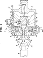
- Fig. 1 is a sectional view showing an embodiment of a robot hand according to the present invention;
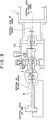
- Fig. 2 is a sectional view taken along the line A-A in Fig. 1;
- Fig. 3 is an explanatory view showing the positional relationship between die stamping impressions, a grip hand and a robot arm when a blank workpiece to be forged is loaded on a stamping impression of a die prior to forging;
- Fig. 4 is an explanatory view showing the positional relationship between the stamping impressions of a die, the grip hand and the robot arm after forging;
- Fig. 5 is a plan view showing an example of the arrangement of the die and stamping impressions within a forging machine; and
- Fig. 6 is an elevational sectional view showing a case in which the robot hand is provided with a motor.
- The present invention will now be described in detail by way of an embodiment.
- A robot of the present embodiment is adapted to grip a blank workpiece W to be forged at one end thereof along the length thereof for facilitating the forging as shown in Fig. 1. A robot arm 1 (Fig. 3) is movably mounted on the main body (not shown) of the robot. The robot arm 1 is provided with a
robot hand 2 at the front end thereof. Therobot hand 2 comprises agrip hand 3 for directly gripping the blank workpiece W at one end of the workpiece along the length thereof and agrip support 2a into which the rear portion of thegrip hand 3 is inserted for supporting thegrip hand 3. - The
grip support 2a is opened at the front end thereof and is hollow in shape. Thegrip support 2 is provided therein with a mechanism for holding the rear side portion of thegrip hand 3 so that thegrip hand 3 is vertically and laterally movable and can be inclined. The rear side portion of thegrip hand 3 is formed in such a manner that it is held so as to be forwardly or backwardly movable. - An inner chamber of the
grip support 2a and the rear portion of thegrip hand 3 constitute a buffer portion for buffering the impact vibrations of thegrip hand 3 which occur due to hammering during forging. The buffering portion reduces or mitigates the impact on hammering to protect therobot hand 2 per se and the robot main body of the robot and enables accurate movement of the workpiece to the stamping impressions by following the displacement of thegrip hand 3 which grips the workpiece W. - As mentioned above, the
grip support 2a includes anouter cylinder 4 which is hollow therein and is opened at the front end thereof. A spherical bearingseat 5 is held on the inner periphery of the open end portion of theouter cylinder 4 so that the spherical bearingseat 5 is movable in vertical and lateral directions. The spherical bearingseat 5 is adapted to support or bear thespherical surface 13 which is formed on the front portion of thegrip guide 12 which will be described hereafter. The spherical bearingseat 5 is annular in shape and the inner annular peripheral surface thereof functions as a spherical bearing seat. - The annular spherical bearing
seat 5 includes spherical bearingseat halves seat halves seat halves annular elastomer 5c. - The
elastomer 5c functions to bias the front and rear sphericalbearing seat halves ring piston 7 and a guide 6 by its spring force for preventing the spherical bearing seat halves from moving in vertical and lateral directions with its frictional force. Theelastomer 5c may be, for example, urethane rubber. - The
elastomer 5c is in contact with thespherical surface 13 of thegrip guide 12 at the inner peripheral surface thereof to prevent the grip guide 12 from inclining by its frictional resistance. Even if no hydraulic pressure is applied to thering piston 7 which will be described hereafter, theelastomer 5c serves to maintain thegrip hand 3 at a constant position. Since the above mentioned constraint is due to the frictional force of theelastomer 5c, the sphericalbearing seat halves grip guide 12 would be displaced or inclined if an impact force which is larger than this frictional force is applied to thegrip hand 3. - A guide 6 which is in contact with the rear side of the annular
spherical bearing seat 5 to constrain it, is provided on the inner peripheral surface of the inner wall of theouter cylinder 4 on the opening side thereof. The guide 6 is formed along the inner periphery of theouter cylinder 4 and projects therefrom in an inner radial direction thereof. Thering piston 7 is mounted on the peripheral edge portion 8 of the opening of theouter cylinder 4, which is located in front of the guide 6 and biases the front side of the annularspherical bearing seat 5 to the guide 6. - The annular
spherical bearing seat 5 is sandwiched on the front and rear sides thereof between thering piston 7 and the guide 6 so that it is held in position. Thering piston 7 is arranged so that its biasing force upon thespherical bearing seat 5 is controlled with fluid pressure. Theelastomer 5c may be omitted, for example, by making the hydraulic pressure applied upon thering piston 7 changeable between high and low levels and by lowering the biasing force of thering piston 7 to a force corresponding to the above mentioned elastic force of theelastomer 5c. -
Center returning actuators 9 each including a hydraulic or pneumatic actuator or the like are adapted to return the vertically and/or laterally displacedspherical bearing seat 5 to a neutral position in vertical and lateral directions. A total of at least 3, center returning actuators 9 (four actuators in this embodiment) are provided at angles of 90° in theouter cylinder 4 between thering piston 7 and the guide 6. Each of thecenter returning actuators 9 includes a piston which is movable in a plane perpendicular to a forward or rearward direction. Eachcenter returning actuator 9 is mounted in such a manner that at the front end of the piston of eachcenter returning actuator 9 biases the outer peripheral surface of thespherical bearing seat 5 in an inner radial direction within theouter cylinder 4. Eachcenter returning actuator 9 is controlled with hydraulic pressure. When supply of the hydraulic fluid to thecenter returning actuator 9 ceases, the piston is retracted. -
Inclination returning actuators 10 each including a hydraulic or pneumatic actuator or the like are adapted to return theinclined grip hand 3 to an original horizontal position. A total of at least 3 (4 in this embodiment)inclination returning actuators 10 are provided at angles of 90° in theouter cylinder 4 which is to the rear of the guide 6. Each of theinclination returning actuators 10 includes a piston which is movable in a plane perpendicular to a forward or rearward direction. Eachinclination returning actuator 10 is mounted in such a manner that the front end of the piston of theinclination returning actuator 10 biases agrip guide 12 which is fitted on the rear portion of thegrip hand 3 in an inner radial direction within theouter cylinder 4. Eachinclination returning actuator 10 is controlled with hydraulic pressure. When supply of the hydraulic fluid to thecenter returning actuator 10 ceases, the piston is retracted. - A forward returning actuator 11 including a hydraulic or pneumatic actuator or the like is adapted to return the axially displaced
grip hand 3 to an original forward position and is provided within theouter cylinder 4 at the rear end thereof. The forward returning actuator 11 includes a piston which is axially movable. The forward returning actuator 11 is mounted in such a manner that the front end of the forward returning actuator 11 biases the rear end of thegrip hand 3 in a forward direction. The forward returning actuator 11 is controlled with hydraulic pressure. When supply of the hydraulic fluid to the forward returning actuator 11 ceases, the piston is retracted. - The
grip hand 3 includes a plurality offingers 3a for gripping a workpiece, agrip body 3b for supporting the plurality offingers 3a so that they are movable, and apiston 3c which moves to operate theplurality fingers 3a for gripping the blank workpiece forwards or backwards within thegrip body 3b. Thegrip guide 12 is fitted to the rear portion of thegrip hand 3. Specifically, thegrip guide 12 is formed with ahole 12a therein into which the rear portion of thegrip hand 3 is fitted so that thegrip hand 3 is axially movable. Thegrip hand 3 is formed on the outer periphery thereof at the rear end thereof with astopper 3d which projects in an outer radial direction. Thisstopper 3d serves to prevent the grip guide 12 from being removed from the rear end of thegrip hand 3. - The
grip guide 12 is formed on the outer surface thereof on the front side thereof with aspherical surface 13 which is seated on the above mentionedspherical bearing seat 5 so that thegrip guide 12 can be inclined. The outer peripheral surface of thegrip guide 12 on the rear side which is in contact with the front ends of the pistons of theinclination returning actuators 10 is formed intoflat surfaces 12b. The number offlat surfaces 12b is equal to the number ofinclination returning actuators 10. - A
brake liner 14 is provided on the inner periphery of thehole 12a which is on the rear side of thegrip guide 12. Apiston 15 for biasing thebrake liner 14 is disposed on the outer side of thebrake liner 14 at the rear end of thegrip guide 12. Thepiston 15 can bias upon the outer periphery of the grip body via theliner 14 for preventing the grip body from moving in an axial direction thereof. Acotter 16 is provided between thehole 12a and thegrip hand 3 to prevent relative rotation therebetween and to allow forward and rearward movement thereof. - Now, operation of the above mentioned embodiment will be described.
- The
spherical surface 13 of thegrip guide 12 is seated on thespherical bearing seat 5. Accordingly, thegrip guide 12 and thegrip hand 3 which is fitted on theguide 12 are afforded universal inclination and rotation. Thespherical bearing seat 5 which bears thespherical surface 13 of thegrip guide 12 is divided into axially front and rear halves which are separated from each other on the facing sides thereof to form a slight gap. - The front spherical
bearing seat half 5a is biased backwardly by thering piston 7 incorporated in theouter cylinder 4 to bias via theelastomer 5c and thespherical surface 13 of thegrip guide 12 the rear sphericalbearing seat half 5b upon the guide 6 which is the front portion of the outer cylinder 4 (a plane which is perpendicular to the axis of the cylinder 4). Theelastomer 5c may be omitted by making the fluid pressure on thering piston 7 adjustable. In lieu of oneannular ring piston 7, several pistons may be disposed at equal angular spaces. - Two front and rear spherical
bearing seat halves spherical surface 13 of thegrip guide 12 to suppress the free movement of thegrip guide 12 with its frictional force to hold rotation or inclination of thegrip guide 12 in a desired position. Thespherical bearing seat 5, thegrip guide 12 and thegrip hand 3 can be held in a desired position with the frictional force caused due to the biasing force of thering piston 7 without being slid downward. - If an external force which is larger than the above mentioned frictional force is applied to the
grip hand 3 in a vertical or lateral direction, thespherical bearing seat 5, that is, thegrip hand 3 would be moved in a vertical or lateral direction, respectively, or thespherical surface 13, that is, thegrip hand 3 may be inclined around thespherical bearing seat 5 which functions as a fulcrum. - Three or more
center returning actuators 9 are disposed at equal angular spaces (a total of four actuators at angular 90° spaces in the present embodiment) in theouter cylinder 4 which is the opposite side of thespherical bearing seat 5. Thespherical bearing seat 5 is biased in an inner radial direction from the outer side thereof by the pistons of thecenter returning actuators 9. This arrangement enables the vertically or laterally displacedspherical bearing seat 5 to be returned to the initial neutral position. Accordingly, the vertically or laterally displacedgrip hand 3 can be biased so that it is returned to the center axis of theouter cylinder 4. When all the pistons of the plurality ofactuators 9 extend to the extended stroke end, thespherical bearing seat 5 and thegrip hand 3 can be positioned in the center, or the neutral position of theouter cylinder 4. - The rear portion of the
grip guide 12 can be biased to return to the center of theouter cylinder 4 by three or moreinclination returning actuators 10 which are disposed at equal angular spaces in theouter cylinder 4 which is on the rear side and on the outer periphery of thegrip guide 12. When all the pistons extend to the extended stroke end, the rear portion of thegrip guide 12 is positioned centrally of theouter cylinder 4. Accordingly, thegrip guide 12 and thegrip hand 3 can be positioned in the initial horizontal position by the mutual reaction between thecenter returning actuators 9 and theinclination returning actuators 10. - The
flat surfaces 12b, which are as many as theinclination returning actuators 10, are provided on the outer periphery of thegrip guide 12. By biasing the front ends (flattened) of the pistons of theinclination returning actuators 10 on the flat surfaces 12h, the displacedgrip hand 3 can be returned to the initial neutral or home position. - Now, forging of a blank workpiece W which is practically conducted using a die will be described.
- It is assumed that a
die 30 is formed with a plurality of stampingimpressions - Firstly, hydraulic fluid is supplied to the actuators provided in the
grip support 2a to position thegrip hand 3 in the initial position for aligning the axis of the robot arm 1 with the axis of thegrip hand 3. - Then hydraulic fluid is supplied into the
grip body 3b to move thepiston 3c in the grip body for gripping the blank workpiece W with thefingers 3a. The arm 1 is moved to align the central axis of thefirst stamping impression 31 with that of the robot arm 1 for loading the workpiece W slightly on thefirst stamping impression 31. - While the workpiece W is loaded on the
first stamping impression 31, introducing of hydraulic fluid into thecenter returning actuators 9, theinclination returning actuators 10, the forward returning actuator 11 and thering piston 7 is stopped or alternatively, hydraulic or pneumatic pressure upon thering piston 7 is lowered to decrease the constraining force upon thegrip hand 3. Accordingly, thegrip hand 3 is flexibly displaced relative to theouter cylinder 4 of thegrip support 2a. When the workpiece is loaded on the stampingimpression 31, the central axis of thegrip hand 3, that is the center of the workpiece W, may be offset in a vertical direction from the center of the robot arm 1 (for example, offset by Y as shown in Fig. 3). If the workpiece W is deformed by hammering or application of a pressure under this condition, the position of thegrip hand 3 is changed from that under predetermined conditions (for example, it changes to a condition of Fig. 4). - The position of the
grip hand 3 is maintained by applying a pressure to thering piston 7. In this case, maintaining of the position of thegrip hand 3 is achieved by increasing the friction between the sphericalbearing seat half 5b and the guide 6 and the friction between the sphericalbearing seat halves spherical surface 13 of thegrip guide 12 by applying a pressure on thepiston ring 7, or alternatively by increasing the friction between thegrip hand 3d and thebrake liner 14 by applying a pressure upon thepiston 15. When the workpiece W is removed from the first stamping impression and is then loaded on the second stamping impression, the workpiece W can be easily aligned with the second stamping impression by aligning the central axis of the first stamping impression with the central axis of the robot arm 1. - If the central axis of the robot arm 1 is always aligned with the central axis of the stamping impression of the die, accurate loading on next stamping impression can be made with reference to the central axis of the robot arm 1 whenever the
grip hand 3 is deformed in any way due to deformation of the gripped portion of the workpiece W. - In the case of forging which requires movement of a workpiece to a plurality of stamping impressions, on starting of forging, the
grip hand 3 is in a given neutral position with fourcenter returning actuators 9 disposed around thegrip hand 3, theinclination returning actuators 10 and the forward returning actuator 11 which is provided in rear of thecylinder 4. Thespherical bearing seat 5 and thebrake liner 14 are biased upon thegrip hand 3 by thering piston 7 and thepiston 15 which are actuated by the hydraulic pressure so that the position of thegrip hand 3 is maintained. Under this condition, the workpiece W is gripped and is loaded in position on thefirst stamping impression 31 between upper and lower dies. - When introducing of fluid into the
center returning actuators 9, theinclination returning actuators 10, the forward returning actuator 11, thering piston 7 and thepiston 15 is stopped, thegrip hand 3 is held with a small holding force caused by only the friction between the supportingspherical surface 13 of thegrip guide 12 and theelastomer 5c. Although thegrip hand 3 is held in a neutral position under this condition, it can be freely displaced in response to an external force which is generated by forging impact. - When forging is conducted under conditions shown in Fig. 3, for example, elongation (L) and/or bending (α) of the workpiece W occurs as shown in Fig. 4. The
grip hand 3 is held in the displaced position as mentioned above, if hydraulic pressure is applied to thering piston 7 and thepiston 15 immediately after hammering. - The central axis of the robot arm 1 is aligned with the central axis of the die stamping impression. The robot arm 1 is moved to the next stamping impression. If the central axis of next robot arm 1 is aligned with the central axis of the
die stamping impression 32, the workpiece W can be accurately loaded on thenext stamping impression 32 no matter how the position and orientation of thegrip hand 3 is changed. - Supply of hydraulic pressure to the
ring piston 7 and thepiston 15 is removed immediately before next hammering action as is done in the first hammering. While holding of thegrip hand 3 is carried out with only the friction between the supportingspherical surface 13 of thegrip guide 12 and theelastomer 5c, the next hammering action is conducted. - Thereafter, similar steps as mentioned above are repeated. After hammering on the
last stamping impression 33 is completed, hydraulic pressure is applied to thering piston 7 and thepiston 15 for holding thegrip hand 3 and a product workpiece is released in next predetermined position. - Thereafter, the robot is returned to a position where it will grip the next workpiece W. At the returning step, supply of the hydraulic pressure to the
ring piston 7 and thepiston 15 is stopped and thegrip hand 3 is returned to a given neutral position by operating fourcenter returning actuators 9 provided around thegrip hand 3, theinclination returning actuators 10 and the froward returning actuator 11 which is provided in the rear of theouter cylinder 4 in a proper timing relationship. - Then, hydraulic pressure is applied to the
ring piston 7 and thepiston 15 to hold thegrip hand 3 for gripping the next workpiece for forging. Then the above mentioned steps may be repeated. - As mentioned above, a
bearing 17 and aflange 18 are provided in the rear of theouter cylinder 4 of therobot hand 2 and amotor 19 may be mounted on theflange 18, which is then mounted on the robot arm 1. - In case of the thus formed alternative, the whole of the robot hand, that is, the workpiece W can be rotated by rotating the
outer cylinder 4 of therobot hand 2 with an output shaft of the motor. - This enables the workpiece which has been bent in a vertical direction on the first stamping impression to be loaded on the second stamping impression after it is rotated by 90°.
- Products which are bent in a horizontal direction can be forged.
- It is to be understood that the present invention is not limited to only the above mentioned embodiment and that various modifications and alternations can be made within the spirit and scope of the invention as defined in the following claims.
- In accordance with the robot hand for forging of the present embodiment, damages to the
grip hand 3 and the main body of the robot can be prevented by thegrip hand 3 which is universally displaced to absorb the impacts occurring on forging even if forging is conducted while the robot hand grips the workpiece W since the grip hand is provided with a spherical bearing seat and linear guide which enable the hand to be moved in any direction. Further, the forging period of time can be shortened since rehandling of the workpiece is not required whenever the workpiece is successively moved between stamping impressions in the case of forging using a die having a plurality of stamping impressions.
Claims (16)
- A robot hand for gripping a workpiece to be forged comprising
a grip hand for gripping said workpiece to be forged; and
a grip hand support for supporting said grip hand so that said grip hand is movable in a desired direction in an imaginary plane, inclinable in a desired direction in a three-dimensional space around a point on said imaginary plane as a center, movable in an axial direction of said grip hand, and rotatable around an axis;
said grip hand including
a plurality of fingers for gripping said workpiece to be forged; and
a grip body having one end thereof on which said fingers are movably mounted;
said grip hand support including a casing into which the other end portion of said grip body is inserted;
support means disposed in said casing for supporting the other end portion of said grip body so that said grip hand is movable, inclinable and rotatable relative to said casing; and
supporting state changing means for changing the supporting states among a displacement changing state, in which said grip hand is movable, inclinable and rotatable relative to said casing when an external force is applied to said grip hand gripping said workpiece to be forged; a constraining state in which said grip hand, which is displacable relative to said casing, is constrained to make it movement, inclination and rotation impossible unless an external force which is not less than a predetermined force si applied to said grip hand; and an initial neutral position constraining state in which said grip hand which has been displaced relative to said casing is returned to a predetermined initial neutral position and said movement, inclination and rotation of said grip hand is constrained to make its movement, inclination and rotation impossible in said initial neutral position. - A robot hand as defined in claim 1 in which said support means comprises
a grip guide to which the other end portion of said grip body is inserted, a part of the outer periphery of which is formed with a spherical surface, for supporting said grip body so that it is movable in an axial direction thereof; and
a spherical seat which is in contact with said spherical surface of said grip guide for bearing the same so that said grip guide is inclinable in a desired direction within a three dimension space around a point on said imaginary plane;
said casing being assumed of said imaginary plane which is perpendicular to the axis of said casing, said grip guide into which said grip body is inserted and said spherical seat for supporting said grip guide being movable in said imaginary plane. - A robot hand as defined in claim 1 in which said supporting state changing means includes a hydraulic actuator having a piston which is displaceable in an axial direction of said grip body between the movement constraining position, in which the front end portion of said piston is in contact with said grip body and a movement enabling position, in which the front end portion of said piston is not in contact with said grip body.
- A robot hand as defined in claim 1 in which said grip body has an outer peripheral surface thereof which is parallel with its axis; and
said supporting state changing means includes a brake liner which is in contact with the outer peripheral surface of said grip body and a hydraulic actuator for biasing said brake liner to the outer peripheral surface. - A robot hand as defined in claim 2 in which said supporting state changing means includes three or more hydraulic actuators each having a piston which is movable in said imaginary plane between a movement constraining position, in which the front end portion of the piston is in contact with said spherical seat and a movement enabling position, in which the front end portion thereof is not in contact with said spherical seat.
- A robot hand as defined in claim 2 in which said supporting state changing means includes three or more hydraulic actuators in positions remote from the spherical surface on the grip guide, each having a piston which is movable between an inclination constraining position, in which the front end portion of the piston is in contact with said grip guide and an inclinable position in which the front end portion of the piston is not in contact with said grip guide.
- A robot hand as defined in claim 5 in which said supporting state changing means includes three or more hydraulic actuators in positions remote from the spherical surface on the grip guide, each having a piston which is movable between an inclination constraining position, in which the front end portion of the piston is in contact with said grip guide and an inclinable position in which the front end portion of the piston is not in contact with said grip guide.
- A robot hand as defined in claim 2 in which said spherical bearing seat is divided into two parts disposed in front and to the rear of said imaginary plane assumed in said casing; and
said supporting state changing means including a hydraulic actuator having a piston for biasing said divided spherical bearing seats toward said imaginary plane. - A robot hand as defined in claim 7 in which said spherical bearing seat is divided into two parts disposed in front and to the rear of said imaginary plane assumed in said casing; and
said supporting state changing means including a hydraulic actuator having a piston for biasing said divided spherical bearing seats toward said imaginary plane. - A robot hand as defined in claim 8 in which an elastomer is charged between the divided front and rear spherical bearing seats.
- A robot hand as defined in claim 9 in which an elastomer is charged between the divided front and rear spherical bearing seats.
- A robot hand as defined in claim 2 in which said spherical bearing seat is divided into two parts disposed in front and to the rear of said imaginary plane assumed in said casing and an elastomer being charged between the divided front and rear spherical bearing seats.
- A robot comprising
a robot hand as defined in claim 1; and
a robot hand support for rotating said robot hand around an axis of said grip support of said robot hand. - A robot comprising
a robot hand as defined in claim 2; and
a robot hand support for rotating said robot hand around an axis of said grip support of said robot hand. - A robot hand for gripping a workpiece to be forged comprising
a grip for gripping said workpiece to be forged; and
a grip support for supporting said grip so that said grip is movable in directions parallel with and rotatable around three independent axes which are perpendicular to each other in a three-dimensional space and is movable in a resultant direction of two or three axis;
said grip including
a plurality of fingers for gripping said workpiece to be forged; and
a grip body having one end thereof on which said fingers are movably mounted;
said grip support including
a casing into which the other end portion of said grip body is inserted;
support means disposed in said casing for supporting the other end portion of said grip body so that said grip is movable and rotatable relative to said casing; and
supporting state changing means for changing the state among a displacement enabling state in which said grip is movable and/or rotatable relative to said casing when an external force is applied to said grip which grips said workpiece to be forged; a constraining state, in which said grip is constrained to make movement and rotation impossible unless an external force which is not less than predetermined force is applied to said grip after the grip of moved and/or rotated relative to said casing; an initial position constraining state in which said grip is returned to a predetermined initial position relative to said casing and is constrained in said initial position to prevent its movement and rotation even if said grip is moved and/or rotated relative to said casing. - A robot hand as defined in claim 15 in which
said support means comprises
a grip guide to which the other end portion of said grip body is inserted, a part of the outer periphery of which is formed with a spherical surface, for supporting said grip body so that it is movable in a direction of any of said three axes; and
a spherical seat which is in contact with said spherical surface of said grip guide for bearing the same so that said grip guide is rotatable around said three axes;
wherein, said casing being formed in such a manner that said grip guide to which said grip body is inserted and said spherical seat for bearing said grip guide are movable within said casing.
Priority Applications (3)
| Application Number | Priority Date | Filing Date | Title |
|---|---|---|---|
| US08/243,324 US5577902A (en) | 1994-05-16 | 1994-05-16 | Robot hand for forging working |
| EP94107614A EP0683017B1 (en) | 1994-05-16 | 1994-05-17 | Robot hand for forging working |
| DE1994617217 DE69417217T2 (en) | 1994-05-17 | 1994-05-17 | Robotic hand for ironwork |
Applications Claiming Priority (2)
| Application Number | Priority Date | Filing Date | Title |
|---|---|---|---|
| US08/243,324 US5577902A (en) | 1994-05-16 | 1994-05-16 | Robot hand for forging working |
| EP94107614A EP0683017B1 (en) | 1994-05-16 | 1994-05-17 | Robot hand for forging working |
Publications (2)
| Publication Number | Publication Date |
|---|---|
| EP0683017A1 true EP0683017A1 (en) | 1995-11-22 |
| EP0683017B1 EP0683017B1 (en) | 1999-03-17 |
Family
ID=26135631
Family Applications (1)
| Application Number | Title | Priority Date | Filing Date |
|---|---|---|---|
| EP94107614A Expired - Lifetime EP0683017B1 (en) | 1994-05-16 | 1994-05-17 | Robot hand for forging working |
Country Status (2)
| Country | Link |
|---|---|
| US (1) | US5577902A (en) |
| EP (1) | EP0683017B1 (en) |
Cited By (4)
| Publication number | Priority date | Publication date | Assignee | Title |
|---|---|---|---|---|
| CN108339923A (en) * | 2018-02-01 | 2018-07-31 | 湖北三峡职业技术学院 | Manipulator for the automatic roll forging of connecting rod |
| EP3318372A3 (en) * | 2016-10-16 | 2019-03-13 | The Boeing Company | Method and apparatus for compliant robotic end-effector |
| WO2021089620A1 (en) * | 2019-11-08 | 2021-05-14 | Fipa Holding Gmbh | Holder for an actuator |
| CN114453552A (en) * | 2022-01-22 | 2022-05-10 | 德清县鑫宏锻造有限公司 | Forging furnace body based on traditional forging process |
Families Citing this family (22)
| Publication number | Priority date | Publication date | Assignee | Title |
|---|---|---|---|---|
| US5941679A (en) * | 1997-10-27 | 1999-08-24 | Fanuc Robotics North America, Inc. | Automotive door opening robot assembly |
| US7188879B2 (en) * | 2001-11-06 | 2007-03-13 | Phd, Inc. | Slide gripper assembly |
| WO2009023511A1 (en) * | 2007-08-10 | 2009-02-19 | Fanuc Robotics America, Inc. | Magnetic tool for robots |
| US8220366B1 (en) | 2009-10-20 | 2012-07-17 | Honda Motor Co., Ltd. | Self-centering drive socket assembly and method |
| JP5962151B2 (en) * | 2012-04-02 | 2016-08-03 | 富士通株式会社 | Robot hand and robot |
| US9616580B2 (en) | 2012-05-14 | 2017-04-11 | Sarcos Lc | End effector for a robotic arm |
| US10766133B2 (en) | 2014-05-06 | 2020-09-08 | Sarcos Lc | Legged robotic device utilizing modifiable linkage mechanism |
| US10406676B2 (en) | 2014-05-06 | 2019-09-10 | Sarcos Lc | Energy recovering legged robotic device |
| US10765537B2 (en) | 2016-11-11 | 2020-09-08 | Sarcos Corp. | Tunable actuator joint modules having energy recovering quasi-passive elastic actuators for use within a robotic system |
| US10919161B2 (en) | 2016-11-11 | 2021-02-16 | Sarcos Corp. | Clutched joint modules for a robotic system |
| US10828767B2 (en) | 2016-11-11 | 2020-11-10 | Sarcos Corp. | Tunable actuator joint modules having energy recovering quasi-passive elastic actuators with internal valve arrangements |
| US10821614B2 (en) | 2016-11-11 | 2020-11-03 | Sarcos Corp. | Clutched joint modules having a quasi-passive elastic actuator for a robotic assembly |
| US11331809B2 (en) | 2017-12-18 | 2022-05-17 | Sarcos Corp. | Dynamically controlled robotic stiffening element |
| US11351675B2 (en) | 2018-12-31 | 2022-06-07 | Sarcos Corp. | Robotic end-effector having dynamic stiffening elements for conforming object interaction |
| US11241801B2 (en) | 2018-12-31 | 2022-02-08 | Sarcos Corp. | Robotic end effector with dorsally supported actuation mechanism |
| US10906191B2 (en) | 2018-12-31 | 2021-02-02 | Sarcos Corp. | Hybrid robotic end effector |
| US11833676B2 (en) | 2020-12-07 | 2023-12-05 | Sarcos Corp. | Combining sensor output data to prevent unsafe operation of an exoskeleton |
| JP2024022357A (en) * | 2022-08-05 | 2024-02-16 | 川崎重工業株式会社 | Hand and robot system |
| US11826907B1 (en) | 2022-08-17 | 2023-11-28 | Sarcos Corp. | Robotic joint system with length adapter |
| US11717956B1 (en) | 2022-08-29 | 2023-08-08 | Sarcos Corp. | Robotic joint system with integrated safety |
| US11924023B1 (en) | 2022-11-17 | 2024-03-05 | Sarcos Corp. | Systems and methods for redundant network communication in a robot |
| US11897132B1 (en) | 2022-11-17 | 2024-02-13 | Sarcos Corp. | Systems and methods for redundant network communication in a robot |
Citations (4)
| Publication number | Priority date | Publication date | Assignee | Title |
|---|---|---|---|---|
| DE1527363A1 (en) * | 1964-08-05 | 1969-08-21 | Sack Gmbh Maschf | Forge manipulator |
| US3893217A (en) * | 1974-12-13 | 1975-07-08 | Bendix Corp | System and method for automatic insertion of pins in holes |
| FR2379848A1 (en) * | 1977-02-03 | 1978-09-01 | Inst Sup Materiaux Const Mec | Automatic workpiece positioning system - operates using intermediate clamping arm which provides flexible or rigid retention |
| FR2619043A1 (en) * | 1987-08-05 | 1989-02-10 | Electricite De France | Grinding machine carrier with a pneumatic thrust cylinder for robot |
Family Cites Families (4)
| Publication number | Priority date | Publication date | Assignee | Title |
|---|---|---|---|---|
| NL7901956A (en) * | 1979-03-12 | 1980-09-16 | Leuven Res & Dev Vzw | MOVEMENT CONTROL DEVICE. |
| JPS597032A (en) * | 1982-07-06 | 1984-01-14 | Mitsubishi Heavy Ind Ltd | Green tire supply device |
| JPS60103690A (en) * | 1983-11-10 | 1985-06-07 | 富士通株式会社 | Condenser-containing ceramic substrate |
| JPH04228236A (en) * | 1990-12-27 | 1992-08-18 | Aichi Steel Works Ltd | Forging method and apparatus used therefor |
-
1994
- 1994-05-16 US US08/243,324 patent/US5577902A/en not_active Expired - Lifetime
- 1994-05-17 EP EP94107614A patent/EP0683017B1/en not_active Expired - Lifetime
Patent Citations (4)
| Publication number | Priority date | Publication date | Assignee | Title |
|---|---|---|---|---|
| DE1527363A1 (en) * | 1964-08-05 | 1969-08-21 | Sack Gmbh Maschf | Forge manipulator |
| US3893217A (en) * | 1974-12-13 | 1975-07-08 | Bendix Corp | System and method for automatic insertion of pins in holes |
| FR2379848A1 (en) * | 1977-02-03 | 1978-09-01 | Inst Sup Materiaux Const Mec | Automatic workpiece positioning system - operates using intermediate clamping arm which provides flexible or rigid retention |
| FR2619043A1 (en) * | 1987-08-05 | 1989-02-10 | Electricite De France | Grinding machine carrier with a pneumatic thrust cylinder for robot |
Cited By (5)
| Publication number | Priority date | Publication date | Assignee | Title |
|---|---|---|---|---|
| EP3318372A3 (en) * | 2016-10-16 | 2019-03-13 | The Boeing Company | Method and apparatus for compliant robotic end-effector |
| US10286556B2 (en) | 2016-10-16 | 2019-05-14 | The Boeing Company | Method and apparatus for compliant robotic end-effector |
| CN108339923A (en) * | 2018-02-01 | 2018-07-31 | 湖北三峡职业技术学院 | Manipulator for the automatic roll forging of connecting rod |
| WO2021089620A1 (en) * | 2019-11-08 | 2021-05-14 | Fipa Holding Gmbh | Holder for an actuator |
| CN114453552A (en) * | 2022-01-22 | 2022-05-10 | 德清县鑫宏锻造有限公司 | Forging furnace body based on traditional forging process |
Also Published As
| Publication number | Publication date |
|---|---|
| EP0683017B1 (en) | 1999-03-17 |
| US5577902A (en) | 1996-11-26 |
Similar Documents
| Publication | Publication Date | Title |
|---|---|---|
| US5577902A (en) | Robot hand for forging working | |
| CA1043364A (en) | Apparatus for supporting and clamping bodies | |
| US5950485A (en) | System for producing bent sheet-metal articles and components of the system | |
| CN111590612A (en) | Clamping device and clamping method for industrial robot | |
| JPH09108767A (en) | Rivet tightening device and operating method for said device | |
| EP1927418A1 (en) | Tool unclamping device | |
| JP2545738B2 (en) | Robot hand for forging work | |
| EP0508881A2 (en) | Clamping apparatus | |
| US4573861A (en) | Apparatus for feeding sheet metal elements to a bending | |
| CN1462226A (en) | Hammer drill and/or chisel hammer | |
| KR100307033B1 (en) | Forged Robot Hand | |
| JPH08323559A (en) | Robot hand device | |
| JP2636122B2 (en) | Robot hand for forging work | |
| US4879893A (en) | Multipurpose swaging machine | |
| JPH07269674A (en) | Buffer for impact on ball screw | |
| US5964026A (en) | Sheet metal work center and method therefor of fabricating worksheets | |
| US20090301164A1 (en) | Hydraulic Processing Pincers | |
| JP3358159B2 (en) | Forming press for crankshaft | |
| US5216930A (en) | Power work arm | |
| CA2150846A1 (en) | Robot compliance device | |
| CN115515735B (en) | Apparatus and method for shaping material by impact | |
| US20240139797A1 (en) | Apparatus for clinch joining | |
| US6009783A (en) | Method in a sheet metal work center and a sheet metal work center | |
| JPH07266155A (en) | Material holding device and working unit | |
| JPH076969Y2 (en) | Dice aligning device |
Legal Events
| Date | Code | Title | Description |
|---|---|---|---|
| PUAI | Public reference made under article 153(3) epc to a published international application that has entered the european phase |
Free format text: ORIGINAL CODE: 0009012 |
|
| AK | Designated contracting states |
Kind code of ref document: A1 Designated state(s): DE GB IT |
|
| RAP1 | Party data changed (applicant data changed or rights of an application transferred) |
Owner name: DIRECTOR-GENERAL OF AGENCY OF INDUSTRIAL SCIENCE A |
|
| 17P | Request for examination filed |
Effective date: 19960409 |
|
| 17Q | First examination report despatched |
Effective date: 19970424 |
|
| GRAG | Despatch of communication of intention to grant |
Free format text: ORIGINAL CODE: EPIDOS AGRA |
|
| GRAG | Despatch of communication of intention to grant |
Free format text: ORIGINAL CODE: EPIDOS AGRA |
|
| GRAH | Despatch of communication of intention to grant a patent |
Free format text: ORIGINAL CODE: EPIDOS IGRA |
|
| GRAH | Despatch of communication of intention to grant a patent |
Free format text: ORIGINAL CODE: EPIDOS IGRA |
|
| GRAA | (expected) grant |
Free format text: ORIGINAL CODE: 0009210 |
|
| AK | Designated contracting states |
Kind code of ref document: B1 Designated state(s): DE GB IT |
|
| ITF | It: translation for a ep patent filed | ||
| REF | Corresponds to: |
Ref document number: 69417217 Country of ref document: DE Date of ref document: 19990422 |
|
| PLBE | No opposition filed within time limit |
Free format text: ORIGINAL CODE: 0009261 |
|
| STAA | Information on the status of an ep patent application or granted ep patent |
Free format text: STATUS: NO OPPOSITION FILED WITHIN TIME LIMIT |
|
| 26N | No opposition filed | ||
| PGFP | Annual fee paid to national office [announced via postgrant information from national office to epo] |
Ref country code: GB Payment date: 20010515 Year of fee payment: 8 |
|
| PGFP | Annual fee paid to national office [announced via postgrant information from national office to epo] |
Ref country code: DE Payment date: 20010626 Year of fee payment: 8 |
|
| REG | Reference to a national code |
Ref country code: GB Ref legal event code: IF02 |
|
| PG25 | Lapsed in a contracting state [announced via postgrant information from national office to epo] |
Ref country code: GB Free format text: LAPSE BECAUSE OF NON-PAYMENT OF DUE FEES Effective date: 20020517 |
|
| PG25 | Lapsed in a contracting state [announced via postgrant information from national office to epo] |
Ref country code: DE Free format text: LAPSE BECAUSE OF NON-PAYMENT OF DUE FEES Effective date: 20021203 |
|
| GBPC | Gb: european patent ceased through non-payment of renewal fee |
Effective date: 20020517 |
|
| PG25 | Lapsed in a contracting state [announced via postgrant information from national office to epo] |
Ref country code: IT Free format text: LAPSE BECAUSE OF NON-PAYMENT OF DUE FEES;WARNING: LAPSES OF ITALIAN PATENTS WITH EFFECTIVE DATE BEFORE 2007 MAY HAVE OCCURRED AT ANY TIME BEFORE 2007. THE CORRECT EFFECTIVE DATE MAY BE DIFFERENT FROM THE ONE RECORDED. Effective date: 20050517 |