EP0682796B1 - A method and plant for handling cans - Google Patents
A method and plant for handling cans Download PDFInfo
- Publication number
- EP0682796B1 EP0682796B1 EP94905304A EP94905304A EP0682796B1 EP 0682796 B1 EP0682796 B1 EP 0682796B1 EP 94905304 A EP94905304 A EP 94905304A EP 94905304 A EP94905304 A EP 94905304A EP 0682796 B1 EP0682796 B1 EP 0682796B1
- Authority
- EP
- European Patent Office
- Prior art keywords
- cans
- crusher
- feed device
- pipe
- collector
- Prior art date
- Legal status (The legal status is an assumption and is not a legal conclusion. Google has not performed a legal analysis and makes no representation as to the accuracy of the status listed.)
- Expired - Lifetime
Links
Images
Classifications
-
- G—PHYSICS
- G07—CHECKING-DEVICES
- G07F—COIN-FREED OR LIKE APPARATUS
- G07F7/00—Mechanisms actuated by objects other than coins to free or to actuate vending, hiring, coin or paper currency dispensing or refunding apparatus
- G07F7/06—Mechanisms actuated by objects other than coins to free or to actuate vending, hiring, coin or paper currency dispensing or refunding apparatus by returnable containers, i.e. reverse vending systems in which a user is rewarded for returning a container that serves as a token of value, e.g. bottles
- G07F7/0609—Mechanisms actuated by objects other than coins to free or to actuate vending, hiring, coin or paper currency dispensing or refunding apparatus by returnable containers, i.e. reverse vending systems in which a user is rewarded for returning a container that serves as a token of value, e.g. bottles by fluid containers, e.g. bottles, cups, gas containers
-
- B—PERFORMING OPERATIONS; TRANSPORTING
- B30—PRESSES
- B30B—PRESSES IN GENERAL
- B30B9/00—Presses specially adapted for particular purposes
- B30B9/32—Presses specially adapted for particular purposes for consolidating scrap metal or for compacting used cars
- B30B9/321—Presses specially adapted for particular purposes for consolidating scrap metal or for compacting used cars for consolidating empty containers, e.g. cans
-
- B—PERFORMING OPERATIONS; TRANSPORTING
- B65—CONVEYING; PACKING; STORING; HANDLING THIN OR FILAMENTARY MATERIAL
- B65G—TRANSPORT OR STORAGE DEVICES, e.g. CONVEYORS FOR LOADING OR TIPPING, SHOP CONVEYOR SYSTEMS OR PNEUMATIC TUBE CONVEYORS
- B65G51/00—Conveying articles through pipes or tubes by fluid flow or pressure; Conveying articles over a flat surface, e.g. the base of a trough, by jets located in the surface
- B65G51/02—Directly conveying the articles, e.g. slips, sheets, stockings, containers or workpieces, by flowing gases
Definitions
- the present invention relates to a method and an apparatus for handling recyclable beverage cans, comprising the use of a can feed device, a can crusher and a collector for compacted cans.
- the object of the present invention is to provide a method and an apparatus for handling recyclable cans, which essentially obviates the above-mentioned problems.
- the invention is thus based on the insight that major advantages can be gained by separating the feed device located in the shop or the like and containing the required can-detecting means for distinguishing between approved and non-approved cans, from the crusher and the collector, which latter devices can thus be separately disposed outside the interference-prone area where the feed device is located, for example outside the shop at the goods reception bay or general refuse collecting area.
- a can conveyor which preferably operates pneumatically, suitably being of the pneumatic tube type.
- the invention ensures that odour problems and other sanitary problems inside the shop are largely eliminated at the same time as the handling of the compacted and collected cans is rendered considerably more effective.
- the cans can be collected directly in a large transport vessel, such as a container, or in a large storage vessel which can easily be emptied into a transport vehicle for recycling.
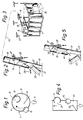
- Fig. 1 is a schematic partial view from above of a conceivable feed device for use in an apparatus according to the invention.
- Fig. 2 is a schematic side view, partly in section, of a part of an embodiment of a conveyor for use in an apparatus according to the present invention.
- Fig. 3 is a schematic perspective view of a part of an apparatus according to the invention, illustrating a preferred embodiment of a combined crusher and collector.
- Fig. 4 is a view similar to Fig. 1, illustrating an alternative embodiment of a feed device.
- Fig. 5 is a view similar to Fig. 2, illustrating a function for preventing a non-approved can from being fed into the conveyor.
- FIG. 1 The embodiment of an apparatus according to the invention as illustrated in Figs 1-3 comprises as main components a feed device 1, illustrated highly schematically, a pipe conveyor 3, a crusher 5 and a collector 7.
- the feed device 1 includes a horizontal rotary disc 9, on one side of which cans are to be inserted standing, as indicated by the arrow 11.
- a guide baffle 13 forces a deposited can to move against a rotating magnetic cylinder 15 having a vertical axis, which detects and removes cans of magnetic material, i.e. non-approved cans.
- the approved cans are however displaced on the disc 4 up to the inlet portion 17 of a pipe 19 being part of the can conveyor 3.
- the inlet portion 17 of the pipe connects with the disc 4 and is open at the bottom towards the direction whence the cans are displaced towards the inlet portion 17.
- the opening 21 of the inlet portion 17 has a width and a height adapted to the size of the cans to be sucked into the pipe 19.
- the inlet portion is inclined slightly rearwards from vertical position relative to the opening 21.
- a can 23 moved up to the opening 21 will remain standing for a short while before being sucked into and up the pipe 19 together with air 25 sucked in.
- a can standing before the opening 21 is detected by a detector 27, whose function will be described in more detail hereinbelow.
- the air flow in the pipe 19 is produced by an air injector 29, blowing air 31 into the pipe 19 obliquely from below.
- This injection of air brings about the air suction in the inlet portion 17 of the pipe and produces a blower conveying effect further on in the pipe 19 on cans sucked into it, when these have passed the injector 29. This ensures efficient conveyance of the cans through the pipe 19 up to the crusher 5.
- the crusher which may be of any suitable type, is disposed directly on a large collector 7, which is suspended by means of stays 33 (not shown in greater detail), so that a can recycling vehicle can easily be backed in underneath the container 7 for emptying collected cans down into the loading compartment of the vehicle via a chute 35 which can be folded down from the container 7.
- a flap device 37 At the air outlet end of the injector 29 in the pipe, there is provided a flap device 37, by means of which a guide flap 39 can be folded out in front of the air flow from the injector 29. In this manner, the air flow will be reversed in the inlet portion 17, as shown by the arrows 41. The reversed air flow ejects any can 43 that may be positioned in front of the opening 21.
- the flap device 37 is controlled by the detector 27. If a can 43 remains too long before the opening 21 without being sucked into the pipe, this means that the can is too heavy and cannot be approved. The air-reversing function now described will thus ensure that such a can 43 is ejected and not conveyed further for compacting and collection.
- Fig. 4 illustrates an alternative embodiment of a feed device for use in an apparatus according to the invention.
- Cans are moved past the inlet opening 21 of the pipe by means of a horizontal endless conveyor belt 45. It is understood that, in this case, cans that are too heavy can be automatically separated, in that there will not be sufficient time for such cans to be sucked in laterally into the opening 21 when passing by. In other words, the adjustment of the suction effect will determine what weight the cans should have to be sucked into the pipe.
Abstract
Description
Claims (10)
- A method for handling recyclable beverage cans, the cans (23) being deposited in a feed device (1), thereafter compacted in a crusher (5) and, in the compacted state, collected in a collector (7), characterised by arranging the feed device (1) at a first location, in a shop, individually and separately arranging the crusher (5) adjacent the collector (7) at a second location outside the interference-prone area where the feed device (1) is located, such as outside the shop at a goods reception bay, a refuse collection space or the like, and transferring deposited cans from the feed device (1) to the crusher (5) via a can conveyor (3), thereby substantially eliminating odour and other sanitary problems in the shop and rendering the handling of the compacted and collected cans significantly more effective.
- A method as claimed in claim 1, characterised by using a can conveyor (3) of pneumatic type, preferably pneumatic tube type.
- A method as claimed in claim 2, characterised by using a can conveyor (3) in which the cans (23) are first sucked into a pipe (19) and thereafter blown through the pipe on to the crusher (5).
- A method as claimed in claim 3, characterised by detecting whether a can which is in position to be sucked into the pipe (19), is sucked into it within a predetermined time, affecting, if such suction does not take place, the air flow in the inlet portion (17) of the pipe, preferably for reversing the direction of the air flow, so that the can (43) concerned is removed from the suction position, preferably blown away therefrom.
- A method as claimed in any one of the preceding claims, characterised by arranging the collector (7) such that it can be emptied downwards into a transport vehicle positioned underneath it, or using as collector a transport container, a large-size vessel or the like.
- An apparatus for handling recyclable beverage cans, comprising a feed device (1) in which cans are deposited for evaluation, a crusher (5) to which approved cans (23) are fed for compacting, and a collector (7) for collecting cans compacted in the crusher, characterised in that the crusher (5) and the collector (7) are separately disposed remote from the feed device (1) which is disposed in a shop, and outside the interference-prone area where the feed device is located, especially outside the shop, the feed device (1) and the crusher (5) being connected to each other by a can conveyor (3), by means of which approved cans (23) deposited in the feed device are conveyed to the crusher (5) for compacting and subsequent collection in the collector (7).
- An apparatus as claimed in claim 6, characterised in the the conveyor (3) is a pneumatic conveyor, preferably of pneumatic tube type.
- An apparatus as claimed in claim 7, characterised in that the conveyor (3) is a pipe conveyor and comprises an air injector (29) producing a suction air flow in the inlet portion (17) of the pipe and an exhaust air flow in the outlet portion of the pipe.
- An apparatus as claimed in claim 8, characterised in that it comprises means (37, 39) for controlling the air injector (29) such that the air flow in the inlet portion (17) of the pipe is altered, preferably reversed, with a view to removing a can (43) which is in suction position and has been detected as a non-approved can.
- An apparatus as claimed in any one of claims 6-9, characterised in that the collector (7) is a container to be emptied downwards into a transport vehicle or a transport vessel, such as a container.
Applications Claiming Priority (3)
| Application Number | Priority Date | Filing Date | Title |
|---|---|---|---|
| SE9300224 | 1993-01-26 | ||
| SE9300224A SE9300224L (en) | 1993-01-26 | 1993-01-26 | Procedure and plant for handling cans - feed and press separate |
| PCT/SE1994/000055 WO1994017497A1 (en) | 1993-01-26 | 1994-01-26 | A method and plant for handling cans |
Publications (2)
| Publication Number | Publication Date |
|---|---|
| EP0682796A1 EP0682796A1 (en) | 1995-11-22 |
| EP0682796B1 true EP0682796B1 (en) | 1998-08-26 |
Family
ID=20388658
Family Applications (1)
| Application Number | Title | Priority Date | Filing Date |
|---|---|---|---|
| EP94905304A Expired - Lifetime EP0682796B1 (en) | 1993-01-26 | 1994-01-26 | A method and plant for handling cans |
Country Status (6)
| Country | Link |
|---|---|
| EP (1) | EP0682796B1 (en) |
| DE (1) | DE69412793T2 (en) |
| ES (1) | ES2120012T3 (en) |
| FI (1) | FI117069B (en) |
| SE (1) | SE9300224L (en) |
| WO (1) | WO1994017497A1 (en) |
Families Citing this family (3)
| Publication number | Priority date | Publication date | Assignee | Title |
|---|---|---|---|---|
| GB9412071D0 (en) * | 1994-06-16 | 1994-08-03 | S & C Thermofluids Ltd | Coanda effect conveying system |
| SE515771C2 (en) | 1998-04-24 | 2001-10-08 | Roy Olson | System and method of feeding returned packaging |
| EP2978698A4 (en) * | 2013-03-26 | 2016-11-23 | Push & Win Ab | A guide member and a system for collecting items by means of said guide member |
Family Cites Families (2)
| Publication number | Priority date | Publication date | Assignee | Title |
|---|---|---|---|---|
| US4179018A (en) * | 1976-12-27 | 1979-12-18 | Miller John H | Method and apparatus for selective recovery of metal containers |
| US4989507A (en) * | 1989-07-10 | 1991-02-05 | Gadar Industries, Inc. | Collector for empty used recyclable beverage cans |
-
1993
- 1993-01-26 SE SE9300224A patent/SE9300224L/en not_active IP Right Cessation
-
1994
- 1994-01-26 DE DE69412793T patent/DE69412793T2/en not_active Expired - Fee Related
- 1994-01-26 WO PCT/SE1994/000055 patent/WO1994017497A1/en active IP Right Grant
- 1994-01-26 ES ES94905304T patent/ES2120012T3/en not_active Expired - Lifetime
- 1994-01-26 EP EP94905304A patent/EP0682796B1/en not_active Expired - Lifetime
-
1995
- 1995-07-25 FI FI953556A patent/FI117069B/en active IP Right Grant
Also Published As
| Publication number | Publication date |
|---|---|
| SE9300224D0 (en) | 1993-01-26 |
| EP0682796A1 (en) | 1995-11-22 |
| FI117069B (en) | 2006-05-31 |
| SE500101C2 (en) | 1994-04-18 |
| SE9300224L (en) | 1994-04-18 |
| ES2120012T3 (en) | 1998-10-16 |
| FI953556A0 (en) | 1995-07-25 |
| FI953556A (en) | 1995-09-25 |
| WO1994017497A1 (en) | 1994-08-04 |
| DE69412793D1 (en) | 1998-10-01 |
| DE69412793T2 (en) | 1999-02-18 |
Similar Documents
| Publication | Publication Date | Title |
|---|---|---|
| US5263591A (en) | Refuse recycling system | |
| US5469783A (en) | Collector for empty used recyclable beverage cans | |
| JPH08500056A (en) | Renewable substance separation device and separation method | |
| EP0682796B1 (en) | A method and plant for handling cans | |
| US4989507A (en) | Collector for empty used recyclable beverage cans | |
| JP2004050106A (en) | Automatic shiitake mushroom separating and sorting facility | |
| US6199702B1 (en) | Method and apparatus for collecting and removing recyclable containers from a redemption center for transport to a separating facility and separating the containers and their components | |
| US5888027A (en) | Method of collecting recyclable containers from a redemption center for separating at a separating facility | |
| JP4480107B2 (en) | Sorting and processing equipment for empty cans | |
| JP2697522B2 (en) | Garbage transport equipment | |
| KR102084012B1 (en) | Automatic opening apparatus of burlap bag to automatically remove powder from burlap bag | |
| US5239920A (en) | Can crusher apparatus | |
| US9295994B2 (en) | Aluminum can system | |
| US5022982A (en) | Rotary drum solid waste air classifier | |
| US6290153B1 (en) | Glass bottle decasing and recovery | |
| JP2555518B2 (en) | Sorting vehicle | |
| JPH07291402A (en) | Dust box for recycling waste | |
| JPH0441303A (en) | Apparatus for collecting empty can | |
| JP3249415B2 (en) | Wind separator | |
| EP0500004A1 (en) | Method and apparatus for reclaiming reusable waste material from discarded containers or the like made from reusable plastics material | |
| US6286569B1 (en) | Material dispensing and recovery system | |
| CN113000545B (en) | Garbage recycling classification recycling device and monitoring system | |
| GB2269774A (en) | Can processing plant | |
| JPH08290115A (en) | Rotary drum-type bag breaking and sorting device | |
| JPH10216639A (en) | Refuse sorter |
Legal Events
| Date | Code | Title | Description |
|---|---|---|---|
| PUAI | Public reference made under article 153(3) epc to a published international application that has entered the european phase |
Free format text: ORIGINAL CODE: 0009012 |
|
| 17P | Request for examination filed |
Effective date: 19950823 |
|
| AK | Designated contracting states |
Kind code of ref document: A1 Designated state(s): DE ES GB IE NL PT |
|
| RAP1 | Party data changed (applicant data changed or rights of an application transferred) |
Owner name: NIMO-VERKEN AB |
|
| GRAG | Despatch of communication of intention to grant |
Free format text: ORIGINAL CODE: EPIDOS AGRA |
|
| 17Q | First examination report despatched |
Effective date: 19971028 |
|
| GRAG | Despatch of communication of intention to grant |
Free format text: ORIGINAL CODE: EPIDOS AGRA |
|
| GRAH | Despatch of communication of intention to grant a patent |
Free format text: ORIGINAL CODE: EPIDOS IGRA |
|
| GRAH | Despatch of communication of intention to grant a patent |
Free format text: ORIGINAL CODE: EPIDOS IGRA |
|
| GRAA | (expected) grant |
Free format text: ORIGINAL CODE: 0009210 |
|
| AK | Designated contracting states |
Kind code of ref document: B1 Designated state(s): DE ES GB IE NL PT |
|
| REF | Corresponds to: |
Ref document number: 69412793 Country of ref document: DE Date of ref document: 19981001 |
|
| REG | Reference to a national code |
Ref country code: ES Ref legal event code: FG2A Ref document number: 2120012 Country of ref document: ES Kind code of ref document: T3 |
|
| REG | Reference to a national code |
Ref country code: IE Ref legal event code: FG4D |
|
| REG | Reference to a national code |
Ref country code: PT Ref legal event code: SC4A Free format text: AVAILABILITY OF NATIONAL TRANSLATION Effective date: 19980924 |
|
| PLBE | No opposition filed within time limit |
Free format text: ORIGINAL CODE: 0009261 |
|
| STAA | Information on the status of an ep patent application or granted ep patent |
Free format text: STATUS: NO OPPOSITION FILED WITHIN TIME LIMIT |
|
| 26N | No opposition filed | ||
| PGFP | Annual fee paid to national office [announced via postgrant information from national office to epo] |
Ref country code: PT Payment date: 20000128 Year of fee payment: 7 Ref country code: IE Payment date: 20000128 Year of fee payment: 7 Ref country code: GB Payment date: 20000128 Year of fee payment: 7 |
|
| PGFP | Annual fee paid to national office [announced via postgrant information from national office to epo] |
Ref country code: ES Payment date: 20000131 Year of fee payment: 7 |
|
| PG25 | Lapsed in a contracting state [announced via postgrant information from national office to epo] |
Ref country code: IE Free format text: LAPSE BECAUSE OF NON-PAYMENT OF DUE FEES Effective date: 20010126 Ref country code: GB Free format text: LAPSE BECAUSE OF NON-PAYMENT OF DUE FEES Effective date: 20010126 |
|
| PG25 | Lapsed in a contracting state [announced via postgrant information from national office to epo] |
Ref country code: ES Free format text: LAPSE BECAUSE OF NON-PAYMENT OF DUE FEES Effective date: 20010127 |
|
| PG25 | Lapsed in a contracting state [announced via postgrant information from national office to epo] |
Ref country code: PT Free format text: LAPSE BECAUSE OF NON-PAYMENT OF DUE FEES Effective date: 20010731 |
|
| GBPC | Gb: european patent ceased through non-payment of renewal fee |
Effective date: 20010126 |
|
| REG | Reference to a national code |
Ref country code: IE Ref legal event code: MM4A |
|
| REG | Reference to a national code |
Ref country code: PT Ref legal event code: MM4A Free format text: LAPSE DUE TO NON-PAYMENT OF FEES Effective date: 20010731 |
|
| NLS | Nl: assignments of ep-patents |
Owner name: ELEIKO SANERA AKTIEBOLAG |
|
| PGFP | Annual fee paid to national office [announced via postgrant information from national office to epo] |
Ref country code: DE Payment date: 20020107 Year of fee payment: 9 |
|
| REG | Reference to a national code |
Ref country code: ES Ref legal event code: FD2A Effective date: 20020916 |
|
| PG25 | Lapsed in a contracting state [announced via postgrant information from national office to epo] |
Ref country code: DE Free format text: LAPSE BECAUSE OF NON-PAYMENT OF DUE FEES Effective date: 20030801 |
|
| PGFP | Annual fee paid to national office [announced via postgrant information from national office to epo] |
Ref country code: NL Payment date: 20090104 Year of fee payment: 16 |
|
| REG | Reference to a national code |
Ref country code: NL Ref legal event code: V1 Effective date: 20100801 |
|
| PG25 | Lapsed in a contracting state [announced via postgrant information from national office to epo] |
Ref country code: NL Free format text: LAPSE BECAUSE OF NON-PAYMENT OF DUE FEES Effective date: 20100801 |